10/17 EINS 516350 AGA TOTAL CONTROL TC3 & TC5 For use in GB & IE PLEASE READ THESE INSTRUCTIONS BEFORE USING THIS APPLIANCE AND KEEP IN A SAFE PLACE FOR FUTURE REFERENCE. Installation Instructions CAUTION: THIS UNIT IS HEAVY, PROPER EQUIPMENT AND ADEQUATE MANPOWER MUST BE USED IN MOVING THE RANGE TO AVOID DAMAGE TO THE UNIT OR THE FLOOR. REMEMBER, when replacing a part on this appliance, use only spare parts that you can be assured conform to the safety and performance specification that we require. DO NOT use reconditioned or copy parts that have not been clearly authorised by AGA.
Transcript
10/17 EINS 516350
AGA TOTAL CONTROLTC3 & TC5
For use in GB & IE
PLEASE READ THESE INSTRUCTIONS BEFORE USING THIS APPLIANCE AND KEEP IN A SAFE PLACE FOR FUTURE REFERENCE.
Installation Instructions
CAUTION: THIS UNIT IS HEAVY, PROPER EQUIPMENT AND ADEQUATE MANPOWER MUST BE USED IN MOVING THE RANGE TO AVOID DAMAGE TO THE UNIT OR THE FLOOR.
REMEMBER, when replacing a part on this appliance, use only spare parts that you can be assured conform to the safety and performance specification that we require.
DO NOT use reconditioned or copy parts that have not been clearly authorised by AGA.
Make a note of your AGA Total Control Serial Number when it is being installed. The serial number can be found behind the magnetic plinth cover.
My AGA Details: Serial No:
AGA Service No:
Date of Installation:
Data badge located behind removable plinth
Contents
1. Health and safety 1
2. Introduction 3
3. Location 4Specifications 5
4. Power Supply 7TC3 7
Hotcupboard TC5 8
5. Vent 9Vent Pipe Connection 9
Oven Venting System Fig. 5.2 10
6. Hotcupboard Installation 11
7. Circuit Diagram AGA TC3 15
8. Circuit Diagram AGA TC5 16
9. Checklist 17
10. Servicing 19
1
The appliance may contain some of the materials that are indicated below. It is the Users/Installers responsibility to ensure that the necessary personal protective clothing is worn when handling where applicable, the pertinent parts that contain any of the listed materials that could be interpreted as being injurious to health and safety, see below for information.
Fire Cement - when handling use disposable gloves.
Glues and Sealants
Exercise caution - if these are still in liquid form use face mask and disposable gloves.
Glass Yarn, Mineral Wool, Insulation Pads, Ceramic Fibre
May be harmful if inhaled. May be irritating to skin, eyes, nose and throat. When handling avoid contact with skin or eyes. Use disposable gloves, face-masks and eye protection. After handling wash hands and other exposed parts. When disposing of the product, reduce dust with water spray, ensure that parts are securely wrapped.
1. Health and safety
Consumer Protection
As a responsible manufacturer, we take care to make sure that our products are designed and constructed to meet the required safety standards when properly installed and used.
nnCHILDREN SHOULD BE KEPT AWAY FROM THE APPLIANCE AS SOME SURFACES CAN BECOME HOT TO THE TOUCH.
The appliance can be used by children aged from 8 years and above and persons with reduced physical, sensory or mental capabilities or lack of experience and knowledge if they have been given supervision or instruction concerning use of the appliance in a safe way and understand the hazards involved. Children less than 8 years of age shall be kept away unless continuously supervised. Cleaning and user maintenance shall not be made by children without supervision.
nnNEVER store flammable materials in the drawer. This includes paper, plastic and cloth items, such as cookbooks, plastic ware and towels, as well as flammable liquids. DO NOT store explosives, such as aerosol cans, on or near the appliance.
nnDO NOT spray aerosols in the vicinity of the cooker while it is on.
nnDO NOT modify this appliance.
nnNEVER place anything aluminium between the saucepan base and the ceramic surface (i.e. cooking mats, aluminium foil, etc).
nnIMPORTANT: Oil is a fire risk, DO NOT leave pans containing oil unattended.
• In the event of a fire cover with a lid and switch OFF the electricity.
• Smother the flames on the hob rather than attempting to remove the pan to the outside.
• Burns and injuries are caused almost invariably by picking up the burning pan to carry outside.
DO NOT hang dish towels on the handrail. Doing so will block the air vent. Blocking the air vent can cause excessive temperature increase to the control panel and prevent easy access.
When the oven (s) are on DO NOT leave any oven door open for long periods, this will affect the temperature of the oven and may allow controls to become hot.
2
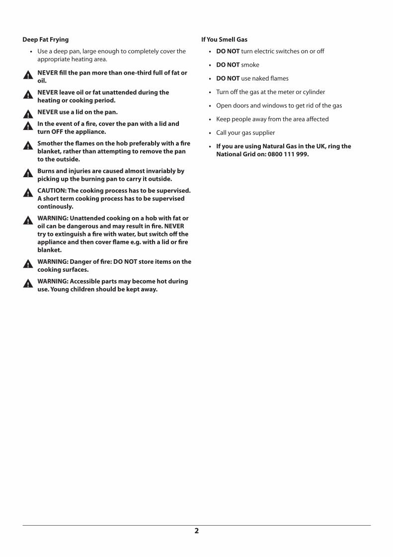
Deep Fat Frying
• Use a deep pan, large enough to completely cover the appropriate heating area.
nnNEVER fill the pan more than one-third full of fat or oil.
nnNEVER leave oil or fat unattended during the heating or cooking period.
nnNEVER use a lid on the pan.
nnIn the event of a fire, cover the pan with a lid and turn OFF the appliance.
nnSmother the flames on the hob preferably with a fire blanket, rather than attempting to remove the pan to the outside.
nnBurns and injuries are caused almost invariably by picking up the burning pan to carry it outside.
nnCAUTION: The cooking process has to be supervised. A short term cooking process has to be supervised continously.
nnWARNING: Unattended cooking on a hob with fat or oil can be dangerous and may result in fire. NEVER try to extinguish a fire with water, but switch off the appliance and then cover flame e.g. with a lid or fire blanket.
nnWARNING: Danger of fire: DO NOT store items on the cooking surfaces.
nnWARNING: Accessible parts may become hot during use. Young children should be kept away.
If You Smell Gas
• DO NOT turn electric switches on or off
• DO NOT smoke
• DO NOT use naked flames
• Turn off the gas at the meter or cylinder
• Open doors and windows to get rid of the gas
• Keep people away from the area affected
• Call your gas supplier
• If you are using Natural Gas in the UK, ring the National Grid on: 0800 111 999.
3
nnTHIS APPLIANCE MUST ONLY BE INSTALLED BY COMPETENT ENGINEERS WHO HAVE BEEN SPECIFICALLY FACTORY TRAINED ON THE PRODUCT AND WHO HAVE THE APPROPRIATE EQUIPMENT.
Any alteration that is not approved by AGA could invalidate the approval of the appliance, operation of the warranty and could affect your statutory rights.
With specific exceptions, the installing of any type of AGA cooker is subject to the respective directions contained in the current issue of the Building Regulations. In addition, planning permission may need to be obtained, which should be applied for separately.
The installation of the appliance must be in accordance with the relevant requirements of the IET Wiring Regulations and Building Regulations. It should be in accordance also with any requirements of the local authority.
In your own interest, and that of safety to comply with the law. all appliances should be installed by an authorised AGA engineer or distributor, in accordance with the relevant regulations.
2. Introduction
Delivery Requirements• The AGA TC3 arrives on 1 pallet
• The AGA TC5 (Hotcupboard Option) arrives on 2 pallets.
There must be access to the kitchen to manipulate a foot print of 1005mm x 740mm. A wooden template (skate with castor wheels) of dimensions 1005mm x 740mm could be used to check if the AGA Total Control fully built appliance is able to fit through the property grounds and doors into its installation position in the kitchen. It must also be considered that the height of the appliance is 960mm off pallet and 1100mm on the pallet, so high level obstacles/restrictions must not be overlooked.
If this skate/template can be manipulated through the property grounds and doors into position, then the AGA can be installed as intended with no re-work.
4
Side Clearances
A 3 mm gap is required each side between the cooker top plate and adjoining work surfaces that may be fitted, this is to allow for the safe removal of the top plate should this be required at a later date.
Where cookers are fitted against side walls a 116 mm clearance is required on the right and left hand side for oven doors access.
If the AGA is to be installed in a brick recess, then the minimum clearance should be increased by at least 10 mm, to allow for the walls not being square.
In addition, a minimum clearance of 1000 mm must be available at the front of the cooker to enable the cooker to be serviced.
Cooker Base or Hearth
It is essential that the base or hearth on which both cooker and module stands should be level and capable of supporting the total weight of one or both units.
The front plinth cover is removable and must not be obstructed by flooring or tiles. If necessary the cooker must be raised by the thickness of the tiles to ensure the plinth can be removed.
Tiling
When the cooker is to stand in a recess or against a wall which is to be tiled, in no circumstances should the tiles overlap the cooker top plate, access to remove the top plate must be allowed for servicing at a later date.
A gap of at least 10mm must be observed between the rear of the top plate, and the wall behind the appliance. If the rear wall is of combustible material there must be a gap of 25mm.
3. Location
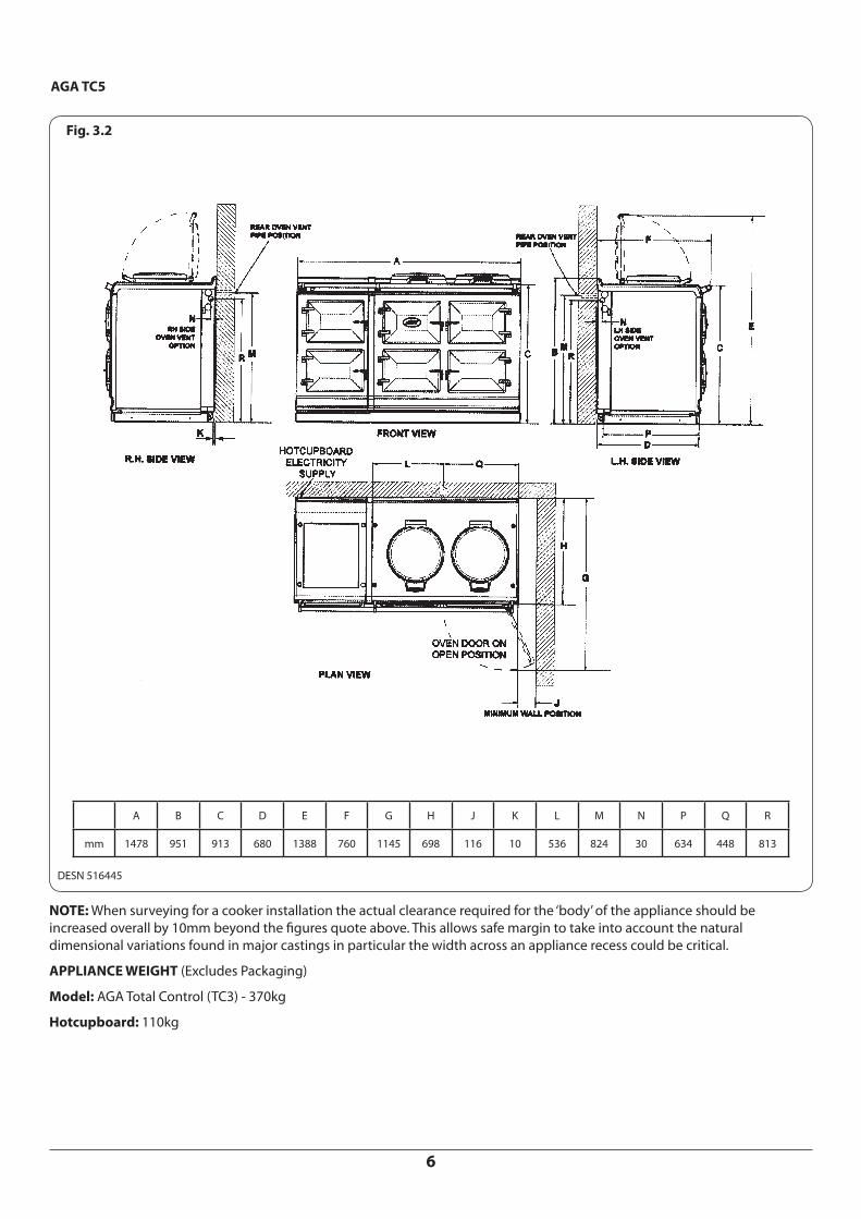
Refer to Fig. 3.1 or Fig. 3.2
It is recommended that any soft material flooring is removed from where the AGA will be installed.
Any adjacent walls that project above the height of the hob must be of heat resistant material.
The side wall above the hob shall be greater than 60 mm from the cooker.
Surfaces over the top of the cooker must not be closer than 650 mm.
The vent slots in the back of the top plate (or shroud) must not be obstructed.
NOTE: It is advisable that the supply cable is routed away from any hot surfaces i.e. hot water/flue pipes.
In the interest of safety, due consideration must be given to the protection of the electric cable to the cooker.
If a supply cord is damaged it must be replaced by the manufacturer, its service agent or similarly qualified persons in order to avoid a hazard.
The appliance is designed for the voltage stated on the rating plate, which is situated in the centre vent slot near the base of the front plate.
Recommended, but not mandatory, to fit an individual Residual Current Device (RCD) for the cooker supply circuit to avoid nuisance tripping.
A minimum clearance of 1000 mm must be available at the front of the cooker to enable it to be serviced.
nnDO NOT install the cooker behind a decorative door in order to avoid overheating.
The complete cooker is floor-mounted and the space in which the appliance is to be fitted must have the following minimum dimensions:-
A minimum clearance of 60 mm is required above the raised insulating cover handle.
This appliance runs continuously, please take note of these IMPORTANT instructions:
Combustible Walls
Houses constructed of combustible materials (such as all-timber or stud wall partitions and batoned plasterboarded walls) require special wall heat protection features.
Non-combustible walls behind a cooker must be of at least 25 mm thick insulation board (Monolux or equivalent), up to hotplate level.
nnNOTE: Ensure electric cabling or plastic services do not pass within or on the outside of the wall, behind or directly above the cooker.
This type of material can age prematurely when exposed to continuous higher ambient temperature.
NOTE: When surveying for a cooker installation the actual clearance required for the ‘body’ of the appliance should be increased overall by 10 mm beyond the figures quote above. This allows safe margin to take into account the natural dimensional variations found in major castings in particular the width across an appliance recess could be critical.
APPLIANCE WEIGHT (Excludes Packaging)
Model: AGA Total Control (TC3) - 370kg
6
DESN 516445
NOTE: When surveying for a cooker installation the actual clearance required for the ‘body’ of the appliance should be increased overall by 10mm beyond the figures quote above. This allows safe margin to take into account the natural dimensional variations found in major castings in particular the width across an appliance recess could be critical.
nnTHIS APPLIANCE IS DESIGNED FOR THE VOLTAGE STATED ON THE RATING PLATE, WHICH IS SITUATED BEHIND THE PLINTH COVER.
nnIf the supply cord is damaged, it must be replaced by the manufacturer, its service agent or similarly qualified person to avoid a hazard.
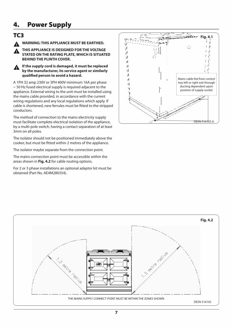
A 1PH 32 amp 230V or 3PH 400V minimum 16A per phase ~ 50 Hz fused electrical supply is required adjacent to the appliance. External wiring to the unit must be installed using the mains cable provided, in accordance with the current wiring regulations and any local regulations which apply. If cable is shortened, new ferrules must be fitted to the stripped conductors.
The method of connection to the mains electricity supply must facilitate complete electrical isolation of the appliance, by a multi-pole switch, having a contact separation of at least 3mm on all poles.
The isolator should not be positioned immediately above the cooker, but must be fitted within 2 metres of the appliance.
The isolator maybe separate from the connection point.
The mains connection point must be accessible within the areas shown in Fig. 4.2 for cable routing options.
For 2 or 3 phase installations an optional adaptor kit must be obtained (Part No. AE4M280354).
THE MAINS SUPPLY CONNECT POINT MUST BE WITHIN THE ZONES SHOWN
Fig. 4.1
Fig. 4.2
DESN 516103 A
DESN 516105
Mains cable fed from control tray left or right exit through
ducting dependent upon position of supply socket
8
Hotcupboard TC5
nnTHE HOTCUPBOARD ATTACHMENT REQUIRES A INDEPEDENT SINGLE PHASE POWER SUPPLY.
nnWARNING: THIS APPLIANCE MUST BE EARTHED.
nnTHIS APPLIANCE IS DESIGNED FOR THE VOLTAGE STATED ON THE RATING PLATE, WHICH IS SITUATED ON A SLIDE-OUT TRAY IN THE HOTCUPBOARD BASE PLATE ABOVE THE PLINTH.
A 230v ~ 50 Hz, 3 amp fused electrical supply is required adjacent to the appliance. External wiring to the unit must be installed using a 3 core silicon - SIHF insulation cable and in accordance with the current wiring regulations and any local regulations which apply.
The method of connection to the mains electricity supply must facilitate complete electrical isolation of the appliance, preferably by a fused double pole switch, having a contact separation of at least 3mm in both poles.
The mains connection point must be accessible within the areas shown in Fig. 4.4 for cable routing options.
The isolator should not be positioned immediately above the hotcupboard, but must be fitted with 2 metres of the appliance Fig. 4.4.
Fig. 4.3
Fig. 4.4
DESN 516446
Mains cable fed from control tray left or right exit through ducting
dependent upon position of supply socket.
Hotcupboard Power Supply
DESN 516447
9
5. Vent
Vent Pipe ConnectionThe appliance is shown with the oven venting from the right-hand side Fig. 5.1.
To gain access remove rear panel (6 screws).
It can also be vented from theleft-hand side, by rotating the copper elbow 180° before fitting the vent pipe.
It can also be vented from the rear using a 45° fitting and exiting through hole in back panel.
Reseal pipe connection with aluminium tape.
When installing a AGA TC5 which is venting to the left hand side, care must always be taken to ensure the vent pipe is fully lagged (using insulation provided). Where the vent pipe passes behind the hotcupboard, ensure that the mains cable is kept away from the hot surface of the vent pipe.
Rear or right hand venting is preferable on AGA TC5 installations.
Fig. 5.1
DESN 516559
10
Oven Venting System Fig. 5.2
The appliance oven venting pipe can be achieved up to a maximum length of 6 metres, through an outside wall. Great care must be taken in all-timber houses.
If the oven vent pipe passes through combustible material, there must be an air gap of at least 25mm around the pipe and preferably wrapped with insulation material.
The max supply to the motor, as calculated should be limited to 22V (DC), for ideal operating conditions.
Calculating the voltage for the particular pipework is as follows:-
1. Keep the pipe run as simple as possible - avoid bends.
2. “Vertical risers” are not permitted.
3. Pipe run should be horizontal - slight downwards slope towards the fan.
Minimum 12 volts for first metre of vent pipe run inclusive of 1 bend
Each extra metre add 1 volt.
Each extra bend add 2 volts
Maximum allowed 22 volts.
Minimum setting is 15 volts.
Fig. 5.2
DESN 516111
11
6. Hotcupboard Installation
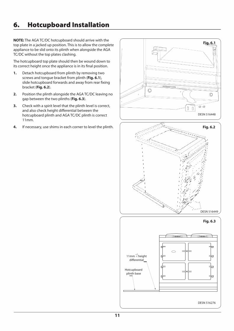
NOTE: The AGA TC/DC hotcupboard should arrive with the top plate in a jacked up position. This is to allow the complete appliance to be slid onto its plinth when alongside the AGA TC/DC without the top plates clashing.
The hotcupboard top plate should then be wound down to its correct height once the appliance is in its final position.
1. Detach hotcupboard from plinth by removing two screws and tongue bracket from plinth (Fig. 6.1), slide hotcupboard forwards and away from rear fixing bracket (Fig. 6.2).
2. Position the plinth alongside the AGA TC/DC leaving no gap between the two plinths (Fig. 6.3).
3. Check with a spirit level that the plinth level is correct, and also check height differential between the hotcupboard plinth and AGA TC/DC plinth is correct 11mm.
4. If necessary, use shims in each corner to level the plinth.
Fig. 6.1
DESN 516448
DESN 516449
Fig. 6.2
DESN 516276
Fig. 6.3
Hotcupboard plinth base
11mm height differential
12
5. Attach hotcupboard plinth to the AGA TC/DC plinth using M6 screws and washers provided (Fig. 6.4).
6. Attach locking screw and jacking screw into plinth. Make sure at this stage that the jacking screw does not protrude beyond outer face of plinth. Ensure locking screw is located into AGA TC/DC plinth but not fully tightened. A gap of approximately 3mm should be present between the plinths apart from at the very front where the hotcupboard spacer plate should be touching the AGA TC/DC plinth.
7. Run a straight edge along the front of the AGA TC/DC plinth, to ensure the front face of both plinths sit squarely against the straight edge (Fig. 6.5).
8. When satisfied both plinths sit squarely, jacking screws can be tightened until they just make contact with the AGA TC/DC plinth, and locking screws can now be tightened.
9. Front jointing bracket can now be hooked into place over the two pot magnets. This will latch the two plinths together (Fig. 6.6).
DESN 516550
Fig. 6.4
DESN 516551
Fig. 6.5
USE STRAIGHT EDGE ACROSS BOTH PLINTHS TO ENSURE PLINTHS ARE ALIGNED SQUARELY
DESN 516553
Fig. 6.6
13
10. Slide hotcupboard onto plinth until rear tongue bracket engages fully into rear of base slot, (Fig. 6.7). Ensure the appliance is aligned squarely with the plinth then proceed to engage the front tongue bracket into the slot on the under side of the base plate.
11. Once satisfied that the front tongue bracket is engaged fully lock it into place by tightening the two M6 screws fully. Ensure that the electrical cable does not come into contact with oven vent pipe from the AGA TC/DC.
12. The hotcupboard top plate is set 5mm higher than the AGA TC/DC top plate. This is to prevent damage to the enamel during installation. Lower the top plate using the adjusters (Fig. 6.8 and Fig. 6.9).
13. Using the stay rod nut adjusting tool, carefully lower the top plate adjusting nuts until the top plate sits at the required height, making sure that the top sits level and matches the height of the AGA TC/DC (Fig. 6.9).
14. For servicing requirement, top plate should be removed by raising adjusters approximately 5mm, the top plate can now be removed easily without causing damage to the enamelled surfaces.
15. When removing the top plate, the switch wiring harness should be disconnected from the main wiring harness at the connection point located at the front left hand side of the appliance, beneath the formex cover sheet.
Fig. 6.7
DESN 516552
Fig. 6.8
Fig. 6.9
DESN 516554
DESN 516555
5mm height difference
14
16. Fit the handrail bracket over the fixing stud located on the top plate. Lock into position by tightening the grub screw nearest the appliance (Fig. 6.10).
17. Slide the complete handrail assembly over the left hand and centre fixing studs. Once the assembly has been fitted to the AGA appliance, fit the handrail endcaps (ensuring the handrail is evenly spaced at each end).
18. The endcaps should be carefully pushed into place until they sit flush with the outside face of each bracket. (A light smear of lubricant, such as washing up liquid can be applied to the end cap rubber ‘O’ rings to aid fitment of endcaps into handrail if required) Fig. 6.11.
19. The handrail can now be locked into place using the grub screws on the underside of the handrail brackets Fig. 6.11.
20. Finally, fit the plinth facia to the magnets on the front of the plinth, making sure that on 5 or 7 oven appliances the right-hand side of the module plinth facia sits against the left-hand side of the AGA TC/DC plinth facia leaving no gap between. Make sure that the plinth facias are centrally located and do not overhang either appliance Fig. 6.12.
21. Commission the AGA TC/DC, as stated in the relevant Installation Instructions and carry out functional test on each of the features of the AGA TC/DC.
DESN 516879
DESN 517533
DESN 516883
Fig. 6.10
Fig. 6.11
Fig. 6.12
15
7. Circuit Diagram AGA TC3
DES
N 5
1748
7
16
8. Circuit Diagram AGA TC5
Code Colour
B Blue
BR Brown
BL Black
OR Orange
G Green
DESN 517488
nnCaution: label all wires prior to disconnection, when servicing controls wiring errors can cause improper and dangerous operation.
nnVerify proper operation after servicing
17
9. Checklist
Hand these instructions to the user for retention, and instruct in the safe operation of the appliance.
Serial No. Tick Box / Not Applicable (N/A)
Check hotplate lids and settings.
Check oven door seals, adjust door alignment if necessary.
Baking and Simmering oven rope seals MUST have a gap between the door hinges. The Roasting Oven is fitted with a continuous seal.
Ensure Roasting Oven roof baffle is fitted in the correct position.
Ensure any plastic film is removed from the inside of the oven doors.
Gain access to controls tray and check mains voltage. DO NOT remove any electrical covers to access mains lead. Terminal measurements can be made through small holes in the cover.
Record voltage
1PH 3PH 3PH 3PH
L1 L2 L3
Ensure vent pipe routing complies with the Installation Instructions.
Record routing
Measure vent pipe run and calculate fan speed voltage. Ensure vent pipe routing complies with the Installation Instruction.
Record routing
Record vent speed voltage
Switch on cooker, set controls to manual and turn on all cooking zones and vent fan. Raise hotplate lids to avoid staining.
Turn on all cooking zones. Refer to lighting procedure for oven burner. Raise hotplate lids to avoid staining.
During warm-up, slow flashing indicator lights will be observed.
18
After 1 hour, check oven and hotplate thermocouple temperatures using Engineers Handset (approx.).
1. Hotspot (330 - 380°C)
2. Simmerspot (200 - 250°C)
3. Roasting Oven (235 - 245°C)
4. Baking Oven (180 - 185°C)
5. Simmering Oven (95 - 115°C)
During warm-up period, check customer’s handset handshakes and instruct customer on it’s application and operation.
If applicable, attach warning hanger (EGLL516660) to handrail when installation is complete. Advise customer to remove and read warning hanger.
Check oven burner for flame stability
Guide customer through the Users Instructions of the appliance, offering best practices on oven maintenance, energy usage, enamel cleaning (boiled vegetable water staining on enamel etc.)
Engineer’s Signature ..................................................................... Date ........................................
19
For continued efficient and safe operation of the appliance, it is important that an annual service is carried out by a competent Engineer. We recommend using Approved Aga Engineers as they have been factory trained and always use genuine Aga spares. In the event of your appliance requiring a service or maintenance, please call AGA Service or your authorised distributor.
Spare Parts
To maintain optimum and safe performance, we recommend that only genuine AGA spare parts are used. These are available from most major spares stockists, including ourselves.
IMPORTANT!
• DO NOT alter or modify the appliance.
nnA hot appliance cannot be serviced.
The cooker should be turned OFF by the user the night preceding the day of servicing so that the appliance will have cooled down by the following morning.
10. Servicing
With AGA Rangemaster’s policy of continuous product improvement, the Company reserves the right to change specifications and make modifications to the appliances
described and illustrated at any time.
www.agaliving.comwww.agacookshop.co.uk
Manufactured ByAGA Rangemaster
Station RoadKetley Telford
Shropshire TF1 5AQEngland
For further advice or information contactyour local AGA Specialist.