As soon as the unit is received, it should be inspected for
possible damage during transit. If you find any damage,
immediately contact the last carrier.
General
These installation instructions are intended as a general
guide only, for use by an experienced, qualified contractor.
The 13GCSX units are single−package air conditioners
designed for outdoor installation on a rooftop or a slab.
The unit must be sized based on heat loss and heat gain
calculations made according to the methods of the Air
Conditioning Contractors of America (ACCA).
The units are shipped assembled. All piping, refrigerant
charge, and electrical wiring are factory−installed and
tested. The units require electric power, gas piping,
condensate drain and duct connections at the point of
installation. In addition, the heating vent hood must be
installed before the unit is placed into operation
Safety Information
CAUTIONAs with any mechanical equipment, personal injurycan result from contact with sharp sheet metaledges. Be careful when you handle this equipment.
IMPORTANTThis unit is charged with HFC−410A refrigerant. Op-erating pressures for units charged with HFC−410Aare higher than pressures in units charged withHCFC−22. All service equipment MUST be rated foruse with HFC−410A refrigerant.
These units must be installed in accordance with all
applicable national and local safety codes.
These instructions are intended as a general guide and do
not supersede local codes in any way. Consult authorities
having jurisdiction before installation.
If components are to be added to a unit to meet local codes,
they are to be installed at the dealer’s and/or customer’s
expense.
Page 4
WARNINGProduct contains fiberglass wool.
Disturbing the insulation in this product duringinstallation, maintenance, or repair will expose youto fiberglass wool dust. Breathing this may causelung cancer. (Fiberglass wool is known to the Stateof California to cause cancer.)
Fiberglass wool may also cause respiratory, skin,and eye irritation.
To reduce exposure to this substance or for furtherinformation, consult material safety data sheetsavailable from address shown below, or contact yoursupervisor.
Lennox Industries Inc.
P.O. Box 799900Dallas, TX 75379−9900
These units are design listed by UL in both the United
States and Canada as follows:
� For use as a forced air furnace with cooling.
� For outdoor installation only.
� For installation on combustible material.
� For use with natural gas or L.P./propane gas only. Use
of L.P./propane gas requires installation of an L.P. con-
version kit, which must be ordered separately.
These units are not suitable for use with conventional
venting systems.
The following safety requirements must also be met when
the 13GCSX units are installed:
1 − Use only with the type of fuel approved for use with this
appliance. Refer to the unit rating plate.
2 − Position, locate and install the 13GCSX unit only as
outlined in these instructions.
3 − Provide adequate clearance around the vent hood as
specified in these instructions.
4 − Do not use an open flame to check for gas leaks. Use a
commercially available soap solution, which has been
designed specifically to check for gas leaks. Refer to
the Gas Supply and Piping section.
5 − Check the unit operation after start−up to make sure
that the 13GCSX is operating within the intended tem-
perature rise range. The duct system must be de-
signed to provide an external static pressure within the
allowable range. Refer to the unit rating plate.
Lennox does not recommend the use of 13GCSX units as a
construction heater during any phase of construction. Very
low return air temperatures, harmful vapors and operation
of the unit with clogged or misplaced filters will damage the
unit.
13GCSX units may be used for heating of buildings or
structures under construction, if the following conditions
are met:
� The vent hood must be installed per these installation in-
structions.
� A room thermostat must control the unit. The use of
fixed jumpers that will provide continuous heating is not
allowed.
� The return air duct must be provided and sealed to the
unit.
� Return air temperature range between 60°F (16°C) and
80°F (27°C) must be maintained.
� Air filters must be installed in the system and must be
maintained during construction.
� Air filters must be replaced upon construction comple-
tion.
� The input rate and temperature rise must be set per the
unit rating plate.
� One hundred percent (100%) outdoor air must be pro-
vided for combustion air requirements during construc-
tion. Installation of this unit in its intended outdoor loca-
tion will accomplish this.
� The heat exchanger, components, duct system, air fil-
ters and evaporator coil must be thoroughly cleaned fol-
lowing final construction clean−up.
� The unit operating conditions (including ignition, input
rate, temperature rise and venting) must be verified ac-
cording to these installation instructions.
NOTE − The Commonwealth of Massachusetts stipu-
lates these additional requirements:
� Gas furnaces shall be installed by a licensed plumb-
er or gas fitter only.
� The gas cock must be �T handle" type.
� When flexible connectors are used, the maximum
length shall not exceed 36".
Location Selection
Use the following guidelines to select a suitable location for
these units.
1 − Unit is designed for outdoor installation only. Unit must
be installed so all electrical components are protected
from water.
2 − Condenser coils must have an unlimited supply of air.
3 − For ground level installation, use a level pre−fabricated
pad or use a level concrete slab with a minimum thick-
ness of 4 inches. The length and width should be at
least 6 inches greater than the unit base. Do not tie the
slab to the building foundation.
4 − Maintain level within a tolerance of 1/4 inch maximum
across the entire length or width of the unit.
Page 5
5 − Do not locate the unit where the combustion air supply
will be exposed to any corrosive substance, including
the following:
Permanent wave solutions,
Chlorinated waxes or cleaners,
Chlorine−based swimming pool chemicals,
Water−softening chemicals,
De−icing salts or chemicals,
Carbon tetrachloride,
Halogen−type refrigerants,
Cleaning solvents (e.g., perchloroethylene),
Printing inks, paint removers, varnishes, etc.,
Cements and glues,
Anti−static fabric softeners used in clothes dryers,
Masonry acid−washing materials,
Chlorinated laundry products,
Hydrochloric acid.
Rigging & Setting Unit
Exercise care when moving the unit. Do not remove any
packaging until the unit is near the place of installation. An
optional lifting lug kit (92M51) may be purchased
separately for use in rigging the unit for lifting. Spreaders
whose length exceeds the largest dimension across the
unit MUST be used across the top of the unit.
CAUTIONBefore lifting a unit, make sure that the weight is dis-tributed equally on the cables so that it will lift evenly.
Figure 1
Accessory Lift Kit
Lifting BracketAccessory
Sheet MetalScrew
Units may also be moved or lifted with a forklift while still in
the factory supplied packaging.
NOTE − Length of forks must be a minimum of 42 inches.
Clearances
All units require certain clearances for proper operation
and service. Refer to figure 2 for the clearances required
for combustible construction, servicing, and proper unit
operation.
NOTE − Do not permit overhanging structures or shrubs to
obstruct condenser air discharge outlet or vent outlet.
Figure 2
Service Clearances − Inches (Millimeters)
3 (76)
48 (1219)
30(762)
24(610)
NOTE − Top Clearance − 36 in. (914 mm)NOTE − Entire perimeter of unit base requiressupport when elevated above mounting surface.
In the U.S. units may be installed on combustible floors
made from wood or class A, B, or C roof covering material.
In Canada, units may be installed on combustible floors.
The products of combustion are discharged through a
screened vent outlet in the front mullion.
Install the unit so that the products of combustion will not
damage the outer building structure.
The vent outlet must be at least 4 feet below, 4 feet
horizontally from and 1 foot above any door, window or
gravity air inlet into the building. In addition, install the unit
so that the vent outlet is at least 3 feet above any forced air
inlet located within 10 feet.
Clearances to the vent outlet must also be consistent with
the requirements of the current National Fuel Gas Code
(Z223.1) and/or the standards of the current CSA B149
codes.
Figure 3 shows the minimum clearances to combustibles
required above and below the vent hood. The minimum
clearance in front of the vent hood is 24 inches.
Install the unit so that snow accumulation will not restric the
flow of the flue products. Allow a required minimum
horizontal clearance of 4 feet from electric meters, gas
meters, regulators and relief equipment. In addtion to the
above requirements, ensure that unwanted ice caused by
condensate is not allowed to accumulate around the unit.
Do not locate the unit on the side of the building where the
Page 6
prevailing winter winds could trap moisture, causing it to
freeze on the walls or on overhangs (under eaves). The
vent outlet should not discharge flue products on a
sidewalk, patio or other walkway where the condensate
could cause the surface to become slippery.
Do not install the unit so that the products of
combustion will be allowed to accumulate within a
confined space and recirculate.
Figure 3
Minimum ClearanceAbove�Vent Hood:Distance from�Topof�Vent Hoodto�Top of Unit
Minimum ClearanceBelow�Vent Hood:Distance from Bottomof�Vent Hood to Baseof Unit
Minimum Clearances to Combustible MaterialsAbove and Below Vent Hood
Vent Hood Installation
The vent hood, screen and screws are shipped inside the
unit in the plastic bag which contains the installation
instructions.
1 − Insert the vent screen into the vent tube Once in-
serted, the screen should be flush with the end of the
tube as shown in figure 4.
Vent Hood Installation
Figure 4
Screen
Vent Hood
Top�View
Slotted side of
vent hood faces
condenser coil.
Screen
Vent�Tube
Front�View
Screen is pre−formed
Vent�Tube
NOTE −Screws
should passthroughsides of
screen tohold screen
in place.
2 − Position the vent hood over the vent tube so that the
slotted side of the hood faces the condenser coil. Use
the four sheet metal screws (provided) to secure the
vent hood to the vent tube. The screws should pass
through the sides of the screen in order to hold the
screen in place.
The vent hood must be installed prior to unit start−up.
Existing Common Vent Systems
The 13GCSX packaged unit may replace an existing fur-
nace which is being removed from a venting system com-
monly run with separate gas appliances. In this case, the
existing vent system is likely to be too large to properly
vent the remaining attached appliances.
Conduct the following test while each appliance is operat-
ing and the other appliances (which are not operating) re-
main connected to the common venting system. If the
venting system has been installed improperly, you must
correct the system as indicated in the general venting re-
quirements section.
1 − Seal any unused openings in the common venting sys-
tem.
2 − Inspect the venting system for proper size and horizontal
pitch. Determine that there is no blockage, restriction,
leakage, corrosion, or other deficiencies which could
cause an unsafe condition.
3 − Close all building doors and windows and all doors be-
tween the space in which the appliances remaining
connected to the common venting system are located
and other spaces of the building. Turn on clothes dry-
ers and any appliances not connected to the common
venting system. Turn on any exhaust fans, such as
range hoods and bathroom exhausts, so they will oper-
ate at maximum speed. Do not operate a summer ex-
haust fan. Close fireplace dampers.
4 − Follow the lighting instructions. Turn on the appliance
that is being inspected. Adjust the thermostat so that
the appliance operates continuously.
5 − After the main burner has operated for 5 minutes, test
for leaks of flue gases at the draft hood relief opening.
Use the flame of a match or candle, or smoke from a
cigarette, cigar, or pipe.
6 − After determining that each appliance connected to the
common venting system is venting properly, (step 3)
return all doors, widows, exhaust fans, fireplace damp-
ers, and any other gas−burning appliances to their pre-
vious mode of operation.
7 − If a venting problem is found during any of the preced-
ing tests, the common venting system must be modi-
fied to correct the problem.
Resize the common venting system to the minimum
vent pipe size determined by using the appropriate
tables in Appendix G. (These are in the current stan-
dards of the National Fuel Gas Code
Page 7
ANSI-Z223.1/NFPA 54 in the USA, and the appropri-
ate Category 1 Natural Gas and Propane appliances
venting sizing tables in the current standards of the
CSA B149 Natural Gas and Propane Installation
Codes in Canada.)
Page 8
Condensate Drain
The 13GCSX unit is equipped with a 3/4 inch FPT coupling
for condensate line connection. Plumbing must conform to
local codes. Use a sealing compound on male pipe
threads.
The drain line must be properly trapped and routed to a
suitable drain. See figure 5 for proper drain arrangement.
The drain line must pitch to an open drain or pump a
minimum of 1 inch per 10 feet to prevent clogging of the
line. Seal around drain connection with suitable material to
prevent air leakage into return air system.
Drain piping should not be smaller than drain connection at
coil. An open vent in drain line will some times be required
due to line length, friction and static pressure. Drains
should be constructed in a manner to facilitate future clean-
ing.
NOTE − The condensate drain line MUST be trapped to
provide proper drainage.
CAUTIONCondensate line connection must be hand−tight-ened. Do not use tools.
ÁÁÁÁÁÁÁÁÁÁ
unit
Minimum Pitch1 in. (25 mm) per10’ (3 m) of line
mountingframe
Figure 5
openvent
Trap must be deep enough to offset maximumstatic difference (Generally, 3 inches minimum).
Typical Condensate Drain
Filters
Filters are not factory−supplied with the unit; however,
optional internally installed filter kits are available. Filter kit
92M54 is used with 2, 2−1/2 and 3−ton units. Filter kit 92M55
is used with 3−1/2, 4 and 5−ton units. The filter kits
accommodate the use of 1", 2" or 4" filters. If the optional
filter kit is not used, a filter must be field−installed.
Filters must always be installed ahead of evaporator coil
and must be kept clean or replaced. Dirty filters will reduce
the airflow of the unit. Filter sizes are shown in table 1.
Table 1Unit Filter Size
Unit Model Filter Size Filter Quantity
−24, −30, −36 20 in. X 25 in. 1
−42, −48, −60 16 in. X 25 in. 2
Supply & Return Duct Connections
The duct system should be designed and sized according
to the methods in Manual Q of the Air Conditioning
Contractors of America (ACCA).
A closed return duct system shall be used. This shall not
preclude use of economizers or outdoor fresh air intake. It
is recommended that supply and return duct connections
at the unit be made with flexible joints.
The supply and return air duct systems should be designed
for the CFM and static requirements of the job. They
should NOT be sized by simply matching the
dimensions of the duct connections on the unit.
CAUTIONWhen fastening duct system to side duct flanges onunit, insert screws through duct flanges only. Do notinsert screws through casing. Outdoor duct must beinsulated and waterproofed.
The 13GCSX unit is shipped ready for horizontal air
discharge (side duct connections). If bottom air discharge
is desired, the covers must be removed from the supply
and return air openings on the bottom of the unit and
re−installed to cover the side openings.
Figure 6
Removing Supply and ReturnAir Opening Covers
Base1.�Remove screw and lift.2.�Slide cover to free back pin.
1
2
Page 9
Compressors
Units are shipped with the compressor mountings
factory−adjusted and ready for operation.
CAUTIONDo not loosen compressor mounting bolts.
Gas Supply and Piping
Check the unit rating plate to confirm whether unit is
equipped for use with natural gas or LP/propane. If
conversion is required use the approved conversion kit.
NOTE − Units are shipped equipped for natural gas, but can
be converted to LP/propane with a conversion kit. Conver-
sion must be performed by an approved licensed pipe
fitter or technician.
All LP/propane gas equipment must conform to the safety
standards of the National Fire Protection Association.
Complete information regarding tank sizing for
vaporization, recommended regulator settings, and pipe
sizing is available from most regulator manufacturers and
LP/propane gas suppliers.
Proper sizing of gas piping depends on the cubic feet per
hour of gas flow required, specific gravity of the gas and
length of run. In the United States, the current National Fuel
Gas Code Z223.1 should be followed in all cases unless
superseded by local codes or gas company requirements.
Refer to tables 2 and 3. In Canada, refer to the current CSA
B.149 installation codes.
Table 2Gas Heat Application Data
UnitHeating Size
Input Rating(Btu)
Output Rating(Btu)
Gas Capacity*(FT3 / HR)
68 67,500 54,000 63
83 82,500 66,000 77
90 90,000 72,000 84
110 110,000 88,000 102
138 137,500 110,000 128
*Based on 1075 Btu per cubic foot of natural gas.
Before connecting piping, check with gas company or
authorities having jurisdiction for local codes or require-
ments. When installing gas supply piping, length of run
from gas meter must be considered in determining pipe
size for 0.5 inch w.c. maximum pressure drop. Do not
use supply pipe smaller than unit gas connection. For
natural gas unit, supply pressure at the unit gas connec-
tion must be a minimum of 5 inches w.c. and a maximum
of 10.5 w.c. For LP/propane gas units, supply pressure
at the unit gas connection must be a minimum of 11 inch-
es w.c. and a maximum of 13.0 inches w.c.
Table 3Gas Pipe Capacity−FT3 / HR
Length in FeetNominal Iron Pipe Size (inches)
1/2 in. 3/4 in. 1 in. 1−1/4 in.
10 132 278 520 1050
20 92 190 350 730
30 73 152 285 590
40 63 130 245 500
50 56 115 215 440
60 50 105 195 400
70 46 96 180 370
80 43 90 170 350
90 40 84 160 320
100 38 79 150 305
The gas supply piping should be routed through the grom-
met on the side of the unit. Refer to figure 7.
Figure 7
Gas Piping and Electrical Conduit Access
Gas Line Entry
ThermostatEntry
Line VoltageEntry
When making piping connections, a drip leg should be
installed on vertical runs to serve as a trap for sediment or
condensate. A 1/8 inch N.P.T. tap accessible for test gauge
connection must be provided in field piping upstream from
gas supply connection to unit. Install a ground joint union
between gas control manifold and the manual main shut−
off valve. See figure 8.
Compounds used on threaded joints of gas piping shall be
resistant to the action of propane/LP gases.
Page 10
Figure 8
unitground joint
union
field provided1/8 in. pressure tap
manual mainshut−off valve
dripleg
gas pipingsupport
Drip Leg Installation
Pressure Test Gas Piping
When pressure testing gas lines, the gas valve must be dis-
connected and isolated. Gas valve can be damaged if sub-
jected to more than 0.5 psig (14 inch w.c.). See figure 9.
If test pressure is equal to or less than 0.5 psig (14 inch
w.c.) shutoff the manual main shut-off valve before pres-
sure testing to isolate unit from gas supply system.
gas valve cap
Manual Main Shut−off Valve Will Not Hold TestPressures in Excess of 0.5 PSIG (14 in. w.c.)
Figure 9
unit
Isolate Gas Valve To Pressure Test
NOTE − Codes may require that manual main shut off valve
and union (furnished by installer) be installed in gas line exter-
nal to unit. Union must be of the ground joint type.
Danger of explosion. Can cause injury orproduct or property damage. Do not usematches, candles, flame or other sourcesof ignition to check for leaks.
WARNING!
After gas piping is complete, carefully check all piping con-
nections (factory and field) for gas leaks. Use soap solution
or other preferred means.
NOTE − In case of emergency shutdown, shut off main
manual gas valve and disconnect main power to unit.
These devices should be properly labeled by installer.
The heating value of the gas may differ with locality. The
value should be checked with the local gas utility.
NOTE − There may be a local gas utility requirement speci-
fying a minimum diameter for gas piping. All units require a
1/2 inch pipe connection at the gas valve.
Gas piping recommendations:
1 − A drip leg and a ground joint union must be installed in
the gas piping.
A ground joint union is recommended by the man-
ifold/valve.
2 − When required by local codes, a manual shut-off valve
may have to be installed outside of the unit.
3 − Use pipe thread sealing compound resistant to pro-
pane gas sparingly on male threads.
4 − The gas supply should be a separate line and installed
in accordance with all safety codes. After the gas con-
nections have been completed, open the main shut-off
valve admitting normal gas pressure to the mains.
Check all joints for leaks with soap solution or other
material suitable for the purpose.
CAUTIONSome soaps used for leak detection are corrosive tocertain metals. Carefully rinse piping thoroughly af-ter leak test has been completed. Do not usematches, candles, flame or other sources of ignitionto check for gas leaks.
5 − The unit and its individual manual shut-off valve must
be disconnected from the gas supply piping system
during any pressure testing of that system at test pres-
sures in excess of 1/2 PSIG (3.48kPa).
IMPORTANTThe unit must be isolated from the gas supply pipingsystem by closing its individual manual shut−offvalve during any pressure testing of the gas supplypiping system at test pressures equal to or less than1/2 psig. See figure 9.
The unit and its individual shut−off valve must be dis-connected from the gas supply piping system duringany pressure testing of the system at test pressuresgreater than 1/2 psig.
6 − A 1/8 inch N.P.T. plugged tapping, accessible for test
gage connections, must be installed immediately up-
stream of the gas supply connection to the furnace.
Page 11
Electrical
All wiring should be done in accordance with the
current National Electric Code ANSI/NFPA No. 70 in the
United States. In Canada, wiring must be done in
accordance with the current CSA C22.2 Part 1. Local
codes may take precedence.
Use wiring with a temperature limitation of 75�C min.; run
the 208 or 230 volt, 60 hertz electric power supply through a
fused disconnect switch to control box of unit and connect
as shown in the wiring diagram located on the inside of the
control access panel.
Unit must be electrically grounded in accordance with local
codes or in the absence of local codes with the National
Electric Code, ANSI/NFPA No. 70 (latest edition) or CSA
C22.2 Part 1 (latest edition).
Power supply to the unit must be N.E.C. Class 1, and must
comply with all applicable codes. A fused disconnect
switch should be field provided for the unit. The switch must
be separate from all other circuits. If any of the wire
supplied with the unit must be replaced, replacement wire
must be of the type shown on the wiring diagram.
Electrical wiring must be sized to carry minimum circuit
ampacity marked on the unit. USE COPPER
CONDUCTORS ONLY. Each unit must be wired with a
separate branch circuit and be properly fused.
CAUTIONWhen connecting electrical power and control wir-ing to the unit, waterproof type connectors MUST beused so that water or moisture cannot be drawn intothe unit during normal operation.
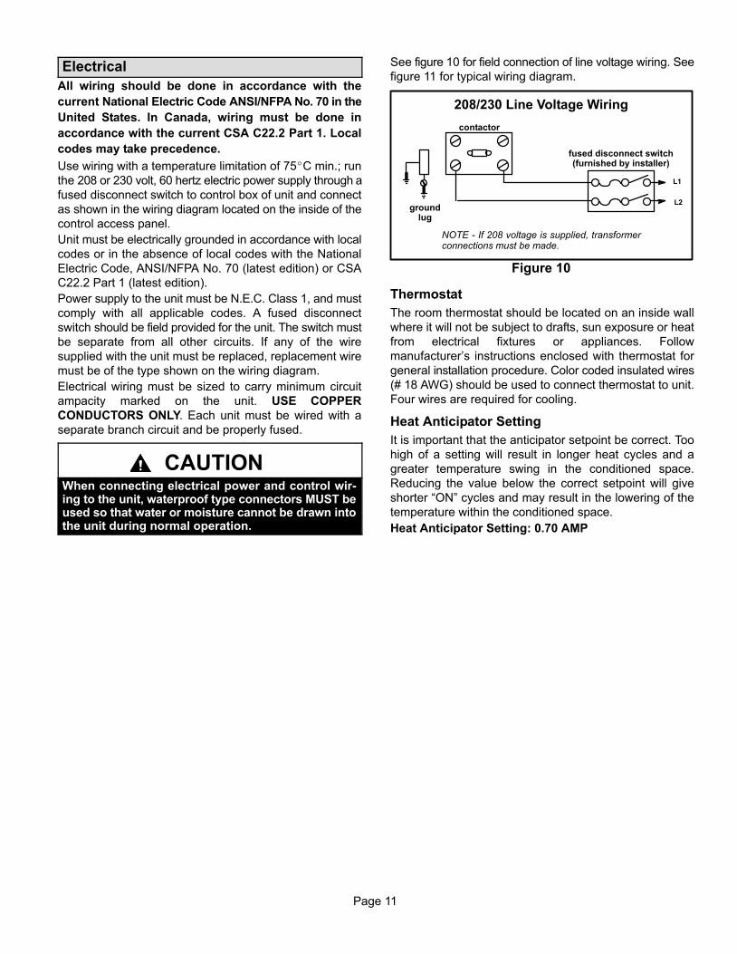
See figure 10 for field connection of line voltage wiring. See
figure 11 for typical wiring diagram.
208/230 Line Voltage Wiring
NOTE − If 208 voltage is supplied, transformerconnections must be made.
L1
groundlug
L2
Figure 10
contactor
fused disconnect switch(furnished by installer)
Thermostat
The room thermostat should be located on an inside wall
where it will not be subject to drafts, sun exposure or heat
from electrical fixtures or appliances. Follow
manufacturer’s instructions enclosed with thermostat for
general installation procedure. Color coded insulated wires
(# 18 AWG) should be used to connect thermostat to unit.
Four wires are required for cooling.
Heat Anticipator Setting
It is important that the anticipator setpoint be correct. Too
high of a setting will result in longer heat cycles and a
greater temperature swing in the conditioned space.
Reducing the value below the correct setpoint will give
shorter �ON" cycles and may result in the lowering of the
temperature within the conditioned space.
Heat Anticipator Setting: 0.70 AMP
Page 12
13
GC
SX
Se
rie
s G
as
Pa
ck
ag
ed
Un
its
Typ
ical
Wir
ing
Dia
gra
m
Page 13
Blower Speed Settings
Electric shock hazard. Can cause injury ordeath. Before attempting to perform anyservice or maintenance, turn the electricalpower to unit OFF at disconnect switch(es).Unit may have multiple power supplies.
WARNING!
13GCSX units are equipped with an indoor blower that is
controlled by the integrated ignition control board.
Factory settings for the blower speed jumpers are given in
the wiring diagram in figure 11. Use tables 4, 5 and 6 to de-
termine the correct air volume for operation in heat and
cool mode.
To change blower speeds, move blower speed tap wire on
the blower motor. Refer to figure 14.
Table 4
13GCSXA−24, 13GCSXA−30 Blower Performance
0 through 0.80 in. w.g. (0 through 200 Pa)
External Static Pressure Range
Horizontal Air Flow
External StaticPressure
Air Volume at Various Blower Speeds
High Medium Low
in. w.g. Pa cfm L/s cfm L/s cfm L/s
.20 50 1470 695 1070 505 880 415
.30 75 1420 670 1060 500 870 410
.40 100 1360 640 1020 480 850 400
.50 125 1290 610 1000 470 820 385
.60 150 1220 575 950 450 790 375
.70 175 1140 540 900 425 740 350
.80 200 1050 495 830 390 690 325
NOTE − All air data is measured external to unit without air filters.1 For down-flow air volume, add 0.05 in. w.g. (12 Pa) to duct static.
Table 5
13GCSXA−36 Blower Performance
0 through 0.80 in. w.g. (0 through 200 Pa)
External Static Pressure Range
Horizontal Air Flow
External StaticPressure
Air Volume at Various Blower Speeds
High Medium Low
in. w.g. Pa cfm L/s cfm L/s cfm L/s
.20 50 1510 715 1060 500 870 410
.30 75 1460 690 1050 495 860 405
.40 100 1400 660 1030 485 840 395
.50 125 1330 630 990 465 820 385
.60 150 1250 590 950 450 790 375
.70 175 1180 555 900 425 750 355
.80 200 1100 520 850 400 680 320
NOTE − All air data is measured external to unit without air filters.1 For down-flow air volume, add 0.05 in. w.g. (12 Pa) to duct static.
Table 6
13GCSXA−42, 13GCSXA−48, 13GCSXA−60
Blower Performance
0 through 0.80 in. w.g. (0 through 200 Pa)
External Static Pressure Range
Horizontal Air Flow
External StaticPressure
Air Volume at Various Blower Speeds
High Medium Low
in. w.g. Pa cfm L/s cfm L/s cfm L/s
.20 50 2090 985 1820 860 1520 715
.30 75 2000 945 1780 840 1480 700
.40 100 1930 910 1730 815 1450 685
.50 125 1820 860 1650 780 1440 680
.60 150 1710 805 1570 740 1410 665
.70 175 1590 750 1480 700 1360 640
.80 200 1480 700 1370 645 1260 595
NOTE − All air data is measured external to unit without air filters.1 For down-flow air volume, add 0.05 in. w.g. (12 Pa) to duct static.
Page 14
Cooling Start−Up
The cooling section is a complete factory package utilizing
an air−cooled condenser. The system is factory−charged
with R−410A refrigerant. The compressor is hermetically
sealed, internally sprung and base−mounted with
rubber−insolated hold−down bolts.
Pre−Start Check List:
1 − Make sure refrigerant lines do not rub against the cabi-
net or each other.
2 − Inspect all electrical wiring, both factory− and field−
installed, for loose connections.
3 − Check voltage at the disconnect switch. Voltage must
be within the range listed on the unit nameplate. If not,
consult power company and have voltage condition
corrected before starting unit.
4 − Recheck voltage with unit running. If power is not with-
in the range listed on the unit nameplate, stop the unit
and consult the power company. Check unit amper-
age. Refer to unit nameplate for correct running amps.
5 − Make sure filter is in place before unit start−up.
Cooling Sequence of Operation
When the thermostat calls for cooling, �R" is closed to �G"
and �Y" (figure 11). This completes the low voltage control
circuit, energizing the compressor, condenser fan motor
and blower motor.
NOTE − At the start of the each cooling demand, the
combustion air blower (draft motor) will operate for 10
seconds.
Unit compressors have internal protection. If there is an
abnormal rise in the compressor temperature, the
protector will open and the compressor will stop.
Blower Delay − Cooling
In the cooling mode, the circulating air blower operation is
delayed for 5 seconds after the compressor starts. The
blower continues to operate for 90 seconds after the
compressor is de−energized.
NOTE − With the proper thermostat and subbase, continu-
ous blower operation is possible by closing the R to G cir-
cuit. Cooling blower delay is also functional in this mode.
System Performance
For maximum performance of this cooling system, the
operating temperatures and pressure should be checked
and superheat determined at Standard ARI test conditions
of 82� F outdoor temperature minus ( − ) 80� F indoor dry
bulb / 67� F indoor wet bulb. If superheat measured
deviates from values in table 7, refrigerant charge should
be adjusted accordingly for maximum performance.
Table 7
Suction Superheat Values
Unit Model No.Suction Superheat
82�F OD minus 80�F IDDB/ 67�F IDWB
13GCSX−2413GCSX−30
16�
13GCSX−36 12�
13GCSX−4213GCSX−4813GCSX−60
16�
Verify system performance using table 8 as a general guide.
Table 8 should not be used for charging unit. Minor varia-
tions in these pressures may be expected due to differences
in installations. Significant differences could mean that the
system is not properly charged or that a problem exists with
some component in the system.
Used carefully, this table could serve as a useful service
guide. Data is based on 80F dry bulb / 87F wet bulb return
air. Allow unit operation to stabilize before taking pressure
readings.
Table 8Normal Operating Pressures
80F db / 87F wb RETURN AIR Air Temperature Entering Outdoor Coil (F)
1 − Check the type of gas being supplied. Be sure it is the
same as listed on the unit nameplate.
2 − Make sure the vent hood has been properly installed.
FOR YOUR SAFETY READ BEFORE LIGHTING
BEFORE LIGHTING the unit, smell all around the fur-
nace area for gas. Be sure to smell next to the floor be-
cause some gas is heavier than air and will settle on the
floor.
Electric shock hazard. Can cause injury
or death. Do not use this unit if any part
has been under water. Immediately call a
qualified service technician to inspect
the unit and to replace any part of the con-
trol system and any gas control which
has been under water.
WARNING!
WARNINGDanger of explosion and fire. Can causeinjury or product or property damage. Youmust follow these instructions exactly.
!
Danger of explosion. Can cause injury or
product or property damage. If overheating
occurs or if gas supply fails to shut off, shut
off the manual gas valve to the appliance
before shutting off electrical supply.
WARNING!
Electric shock hazard. Can cause injury ordeath. Before attempting to perform anyservice or maintenance, turn the electricalpower to unit OFF at disconnect switch(es).Unit may have multiple power supplies.
WARNING!
The gas valve on may be equipped with either a gas con-
trol switch or gas control knob. Use only your hand to
push the switch or turn the gas control knob. Never use
tools. If the the switch will not move or the knob will not
push in or turn by hand, do not try to repair it. Call a quali-
fied service techni cian. Force or attempted repair may
result in a fire or explosion.
This unit is equipped with a direct ignition control. Do not
attempt to manually light the burners.
1 − Turn off electrical power to unit.
2 − Set thermostat to lowest setting.
3 − HoneywellVR8205 Gas Valve with ON/OFF Switch −
Set gas valve switch to ON. See figure 12.
Honeywell VR8205 Gas Valve with Knob − Turn knob
on gas valve counterclockwise to ON. Do not force.
See figure 13.
4 − Turn on electrical power to unit.
5 − Set room thermostat to desired temperature. (If ther-
mostat setpoint temperature is above room tempera-
ture after the pre−purge time expires, main burners will
light).
Figure 12
Honeywell VR8205 Series Gas Valve
Gas Control Switch
Inlet Pressure Tap1/8” NPT
Outlet Pressure Tap1/8” NPT
RegulatorAdjustment
Cap
ON
OFF
Honeywell VR8205 Gas Valve with Control Knob
GAS VALVE SHOWN IN OFF POSITION
MANIFOLDPRESSURE
OUTLET
INLETPRESSURE
PORT
MANIFOLDPRESSURE
ADJUSTMENTSCREW(underbarbedfitting)
Figure 13
To Shut Down:
1 − Turn off electric power to unit.
2 − HoneywellVR8205 Gas Valve with ON/OFF Switch
− Set gas valve switch to OFF.
Honeywell VR8205 Gas Valve with Knob − Turn gas
valve knob clockwise to OFF. Do not force.
Post Start−up Check List (Gas)
After the control circuit has been energized and the heating
section is operating, make the following checks:
1 − Use soap solution to check for gas leaks in the unit pip-
ing as well as the supply piping.
2 − Check for correct manifold gas pressures. See �Man-
ifold Gas Pressure Adjustment."
Page 16
3 − Check the supply gas pressure. It must be within the
limits shown on rating nameplate. Supply pressure
should be checked with all gas appliances in the build-
ing at full fire. At no time should the supply
gas pressure exceed 10.5 inches w.c., nor drop below
5.0 inches w.c. for natural gas units. For propane gas,
supply gas pressure should not drop below 11 inches
w.c. If gas pressure is outside these limits, contact
your gas supplier for corrective action.
4 − Adjust temperature rise to the range specified on the
rating plate.
Checking and Adjusting Gas Input
NOTE − Units must be converted for use with LP/propane
gas. Conversion kit is ordered separately. Conversion
must be performed by an approved licensed pipe fitter
or technician.
The minimum permissible gas supply pressure is 5.0
inches W.C. for natural gas or 11.0 inches W.C. for
LP/propane gas. The maximum inlet gas supply pressure
is 10.5 inches W.C. for natural gas and 13.0 inches W.C. for
LP/propane gas. Gas input must never exceed the input
capacity shown on the rating plate.
Units fueled by natural gas are rated for manifold pressures
of 3.5 inches W.C.
Units fueled by LP/propane gas are rated for manifold
pressures of 10.0 inches W.C.
Measure manifold pressure: Shut off gas supply to the
unit. Remove plug from pressure tap. See figure 12 or 13.
Connect manometer or gauge to the proper pressure tap,
then turn on the gas supply.
The Honeywell VR8205 gas valve has an adjusting screw.
See figure 12 or 13 for adjusting screw location. Remove
the cap and turn the adjusting screw clockwise to increase
pressure and input; turn counterclockwise to decrease
pressure and input. The pressure regulator adjustment is
sensitive. One turn of the adjusting screw results in a large
change in manifold pressure. Replace the adjusting screw
cap.
Final manifold pressure must be within the allowable range
for the gas being used.
For Natural Gas: Check the furnace rate by observing gas
meter, making sure all other gas appliances are turned off.
The test hand on the meter should be timed for at least one
revolution. Note the number of seconds for one revolution.
BTU/HR = Cubic Feet Per Revolution X 3600 X Heating Value
INPUT No. Seconds Per Revolution
The heating value of your gas can be obtained from your
local utility.
For LP/Propane Gas: The only check for the output rate is
to properly adjust the manifold pressure using a manome-
ter. Typical manifold setpoint for installations at altitudes
from 0 to 4500 feet above sea level is 10.0 inches W.C.
High Altitude Information
Ratings shown on the rating plate for elevations up to 4,500
feet. For elevations above 4,500 feet, ratings should be
reduced at a rate of four percent for each 1,000 feet above
sea level. See National Fuel Gas Code Z223.1 (latest
edition) or the requirements of the CSA B149 installation
codes.
Heating Sequence of Operation
When the thermostat calls for heating, W1 is energized.
The ignition control checks high temperature limit and
rollout switches to make sure they are closed. The control
then verifies that the pressure switch is open. If the
pressure switch is closed, the control will flash code 3 on
the LED and will wait indefinitely for the pressure switch to
open. If the pressure switch is open, the control proceeds
to the 30−second pre−purge.
The ignition control energizes the combustion air inducer,
flashes a code 3 on the LED, and waits for the pressure
switch to close.
When the pressure switch has closed, the LED code 3 flash
stops and the control begins the 30−second pre−purge
period. When the pre−purge time has expired, the control
begins the ignition trial.
The ignition control energizes the gas valve, spark
electrode and flame sensor. If the flame is established
within 10 seconds, the control de−energizes the spark. If
flame is not established within 10 seconds, the gas valve
and spark are de−energized. The ignition control will initiate
three ignition trials. If the flame sensor does not sense an
established flame at the end of the third ignition trial, the
igntion control will allow a 1−hour Watchguard period to
pass before allowing additional ignition trials.
Approximately 30 seconds after the flame has been
established, the circulating air blower starts. The ignition
control inputs are continuously monitored to ensure that
limit switch(es), rollout switch and pressure switch are all
closed, and that the flame remains established and heating
demand is present.
When the heating demand is satisfied, the control
immediately de−energizes the gas valve and combustion
air inducer. The circulating air blower operates for 120
seconds after the gas valve is de−energized.
Blower Delay − Heating
In the heating mode, the circulating air blower operation is
delayed for 30 seconds after the flame is established. The
blower continues to operate for 120 seconds after the gas
valve is de−energized.
NOTE − With the proper thermostat and subbase, continu-
ous blower operation is possible by closing the R to G cir-
cuit.
Page 17
Unit Controls
Integrated Ignition Control Board (A3)
The 13GCSX unit includes an integrated ignition control
board which controls the combustion air inducer, gas valve,
spark electrode and indoor blower. The control board
receives signals from the main and auxiliary limit switches,
the rollout switch, the pressure switch and the flame
sensor. LED codes and flash rates are given on page 16.
The ignition control board is shown in figure 14.
Page 18
Figure 14
Ignition Control Board
T1 − SPARK TRANSFORMER
MAIN LIMIT AND ROLLOUT SWITCH RETURN
MAIN LIMIT AND ROLLOUT SWITCH OUT
PRESSURE SWITCH OUT
Integrated Ignition Control Board LED Codes
The ignition control board LED flashes codes which indi-
cate normal or abnormal operations:
Slow Flash −− Normal operation, no call for heat.One flash per second.
Fast Flash −− Normal operation, call for heat.Two flashes per second.
Steady On −− Internal control failure.(Micro−controller failure; self−check).
Code 2 −− System lockout −− Failed to detect or sustainflame.Two flashes in 1 second with a 1−second pause.
Code 3 −− Pressure switch senses incorrect pressure oris stuck in the closed position.Three flashes in 1−1/2 seconds with a 1−second pause.
Code 4 −− Main limit or rollout switch open.Four flashes in 2 seconds with a 1−second pause.
Code 5 −− Flame sensed while gas valve de−energized.Five flashes in 2−1/2 seconds with a 1−second pause.
Limit Control
This control is located inside the heating compartment and
is designed to open at abnormally high air temperatures. It
resets automatically. The limit switch operates when a high
temperature condition, caused by inadequate blower
supply airflow, occurs. The main gas valve is closed. The
circulating air blower will continue to operate until the limit
control closes and the blower off delay period has elapsed.
Pressure Switch
If the combustion air inducer motor should fail or if the vent
system is blocked, the pressure switch prevents the gas
valve from being energized.
Spark Electrode and Flame Sensor Rod
The spark electrode and flame sensor rod are part of the
burner assembly. The spark electrode is typically located
on the far−left burner. The flame sensor rod is typically
located on the far−right burner. If the ignition control does
not receive a signal from the flame sensor indicating that
the burners have established flame, the main gas valve will
close after the 10−second ignition trial period built into the
ignition control.
Rollout Switch
The switch is located above the main burners. In the event
of a sustained main burner rollout the main gas valve is
closed. To reset, push the button on top of the switch.
Auxiliary Limit (−42, −48 & −60 units only)
This control is located in the side of the circulating air blower
housing. If the circulating air blower fails to operate, the
temperature rises and opens the auxiliary limit. The main
gas valve closes. This control resets automatically.
Condenser Fan Clearances
The top of the condenser fan should be 1−1/2 inchs from the
bottom of the top grille. This dimension should be checked
and the fan should be adjusted accordingly any time servic-
ing of the outdoor fan system is required.
Page 19
Maintenance
Periodic inspection and maintenance normally consists of
changing or cleaning filters and (under some conditions)
cleaning the main burners.
FiltersNot supplied. Inspect once a month. Replace disposable or
clean permanent type as necessary. DO NOT replace per-
manent type with disposable.
MotorsIndoor, outdoor fan and vent motors are permanently
lubricated and require no further lubrication. Motors
should be cleaned yearly to prevent the accumulation of
dust and dirt on the windings or motor exterior.
CoilDirt and debris should not be allowed to accumulate on the
coil surfaces or other parts in the air conditioning circuit.
Cleaning should be performed as often as necessary. Use
a brush, vacuum cleaner attachment, or other suitable
means. If water is used to clean the coil, be sure the power
to unit is shut off prior to cleaning.
NOTE − Care should be used when cleaning the coil so that
the coil fins are not damaged.
Do not permit the hot condenser air discharge to be ob-
structed by overhanging structures or shrubs.
To Clean BurnersLight the burners and allow unit to operate for a few min-
utes to establish normal burning conditions. Observe the
burner flames. Compare this observation to figure 15 to
determine if flame is properly adjusted. Flame should be
predominantly blue in color and strong in appearance.
Verify that all burnres are lit and that the flame does not
impinge on the sides of the heat exchanger.
Burner Flame
Figure 15
Burner
HeatExchanger
Burner Flame(Blue Only)
GasManifold
Distorted flame or yellow tipping of the natural gas flame
(or long yellow tips on LP/propane flame) may be caused
by one or more of the following: lint or dirt inside the burn-
er or burner ports; lint or dirt at the air inlet between the
burner and manifold pipe; or an obstruction over the
burner orifice.
Use a soft brush or vacuum to clean the affected areas.
Vent Outlet
Visually inspect vent outlet periodically to make sure that the
there is no buildup of soot and dirt . If necessary, clean to
maintain adequate opening to discharge flue products.
Planned Services
You should expect a service technician to check the follow-
ing items during an annual inspection. Power to the unit
must be shut off for the service technician’s safety.
� Fresh air grilles and louvers Must be open and unob-structed to provide combustion air.
� Burners must be inspected for rust, dirt, or signs of wa-ter.
� Exhaust pipe must be inspected for signs of water,damaged Rust or disconnected joints.
� Unit appearance must be inspected for rust, dirt, signsof water, burnt or damaged wires, or components. Agood coat of auto wax can extend the appearance.
� Blower access door must be properly in place.
� Return air duct must be properly attached and providean air seal to the unit.
� Operating performance � Unit must be observed dur-ing operation to monitor proper performance of the unitand the vent system.
� Combustion gases � Flue products must be analyzedand compared to the unit specifications.
Problems detected during the inspection may make it nec-
essary to temporarily shut down the furnace until the items
can be repaired or replaced.
Pay attention to your unit. Situations can arise between
annual furnace inspections that may result in unsafe op-
eration. For instance, items innocently stored next to the
unit may obstruct the combustion air supply. This could
cause incomplete combustion and the production of car-
bon monoxide gas.
Page 20
Repair Parts & Accessories
The following repair parts are available from your local dealer. When ordering parts, include the complete model number
and serial number which are printed on the unit rating plate. All service must be performed by a licensed professional
installer (or equivalent), service agency, or gas supplier.
Controls Blower Components Heating Components
Rollout Switch Blower Housing Assembly Gas Manifold
Transformer Blower Wheel Main Burner Orifices
Limit Control Blower Motor Main Burners
Gas Valve Blower Motor Mount Heat Exchanger
Ignition Control Blower Motor Capacitor (if used) Cooling Components
Electrode Combustion Air Inducer Compressor
Flame Sensor Fan Blade Evaporator Coil
Auxiliary Limit Fan Motor Drier
Pressure Switch Fan Motor Capacitor Expansion Valve
Blower Control Contactor
Capacitor
Condenser Coil
Accessories
DescriptionLENNOX Cat.
NumberLP/Propane Gas Conversion Kit (heat sizes 68 and 90) 92M57
LP/Propane Gas Conversion Kit (heat sizes 83, 110 and 138) 92M58
Filter Kit (2−ton to 3−ton capacity units) 92M54
Filter Kit (3−1/2−ton to 5−ton capacity units) 92M55


![INSTALLATION INSTRUCTIONS - Lennox 240009135, Rev. C [06/2012] RETAIN THESE INSTRUCTIONS FOR FUTURE REFERENCE These instructions must be affi xed on or adjacent to the boiler. GAS](https://static.documents.pub/doc/80x56/5ab1f3537f8b9ac3348d074a/installation-instructions-lennox-240009135-rev-c-062012-retain-these-instructions.jpg)
