INSTALLATION INSTRUCTIONS PART NUMBER: 21-8030 Equipped with AEM ® Dryflow™ Filter No Oil Required! 2009-2010 CADILLAC Escalade V8-6.2L SEE * NOTE 2009-2010 CHEVROLET Avalanche V8-5.3L SEE * NOTE 2009 CHEVROLET Avalanche V8-6.0L SEE * NOTE 2009-2010 CHEVROLET Silverado 1500 V8-6.2L SEE * NOTE 2009-2010 CHEVROLET Silverado 1500 V8-6.0L SEE * NOTE 2009-2010 CHEVROLET Silverado 1500 V8-5.3L SEE * NOTE 2009-2010 CHEVROLET Silverado 1500 V8-4.8L SEE * NOTE 2009 CHEVROLET Suburban 1500 V8-6.0L SEE * NOTE 2009-2010 CHEVROLET Suburban 1500 V8-5.3L SEE * NOTE 2009 CHEVROLET Tahoe V8-6.2L SEE * NOTE 2009-2010 CHEVROLET Tahoe V8-5.3L SEE * NOTE 2009 CHEVROLET Tahoe V8-4.8L SEE * NOTE 2009-2010 GMC Sierra 1500 V8-6.2L SEE * NOTE 2009-2010 GMC Sierra 1500 V8-6.0L SEE * NOTE 2009-2010 GMC Sierra 1500 V8-5.3L SEE * NOTE 2009-2010 GMC Sierra 1500 V8-4.8L SEE * NOTE 2009-2010 GMC Sierra. Denali V8-6.2L SEE * NOTE 2009 GMC Sierra. 1500 V8-5.3L SEE * NOTE 2009-2010 GMC Yukon V8-5.3L SEE * NOTE 2009-2010 GMC Yukon V8-4.8L SEE * NOTE 2009-2010 GMC Yukon Denali XL. V8-6.2L SEE * NOTE 2009-2010 GMC Yukon Denali. V8-6.2L SEE * NOTE 2010 GMC Yukon XL 1500 V8-6.2L SEE * NOTE 2009 GMC Yukon XL 1500 V8-6.0L SEE * NOTE 2009-2010 GMC Yukon XL 1500 V8-5.3L SEE * NOTE 2010 GMC Yukon XL 2500 V8-6.0L SEE * NOTE
Transcript
INSTALLATION INSTRUCTIONSPART NUMBER: 21-8030
Equipped with AEM® Dryflow™ FilterNo Oil Required!
2009-2010 CADILLAC Escalade V8-6.2L SEE * NOTE 2009-2010 CHEVROLET Avalanche V8-5.3L SEE * NOTE 2009 CHEVROLET Avalanche V8-6.0L SEE * NOTE 2009-2010 CHEVROLET Silverado 1500 V8-6.2L SEE * NOTE 2009-2010 CHEVROLET Silverado 1500 V8-6.0L SEE * NOTE 2009-2010 CHEVROLET Silverado 1500 V8-5.3L SEE * NOTE 2009-2010 CHEVROLET Silverado 1500 V8-4.8L SEE * NOTE 2009 CHEVROLET Suburban 1500 V8-6.0L SEE * NOTE 2009-2010 CHEVROLET Suburban 1500 V8-5.3L SEE * NOTE 2009 CHEVROLET Tahoe V8-6.2L SEE * NOTE 2009-2010 CHEVROLET Tahoe V8-5.3L SEE * NOTE 2009 CHEVROLET Tahoe V8-4.8L SEE * NOTE 2009-2010 GMC Sierra 1500 V8-6.2L SEE * NOTE 2009-2010 GMC Sierra 1500 V8-6.0L SEE * NOTE 2009-2010 GMC Sierra 1500 V8-5.3L SEE * NOTE 2009-2010 GMC Sierra 1500 V8-4.8L SEE * NOTE 2009-2010 GMC Sierra. Denali V8-6.2L SEE * NOTE 2009 GMC Sierra. 1500 V8-5.3L SEE * NOTE 2009-2010 GMC Yukon V8-5.3L SEE * NOTE 2009-2010 GMC Yukon V8-4.8L SEE * NOTE 2009-2010 GMC Yukon Denali XL. V8-6.2L SEE * NOTE 2009-2010 GMC Yukon Denali. V8-6.2L SEE * NOTE 2010 GMC Yukon XL 1500 V8-6.2L SEE * NOTE 2009 GMC Yukon XL 1500 V8-6.0L SEE * NOTE 2009-2010 GMC Yukon XL 1500 V8-5.3L SEE * NOTE 2010 GMC Yukon XL 2500 V8-6.0L SEE * NOTE
2
Description Qty. Part NumberPARTS LIST
A Hose Clamp, 3.56-4.50” 2 9464B Hose, Silicone 4.00x2” Black 1 5-402C Inlet Tube 1 9-0391D Connector, Plastic 3/8” Straight 1 8-125E Hose; 3/8”ID X 12”L 1 5-1012F Hose Clamp, 5/8” 2 4093-3G Bolt, Socket M4-.7 X 8mm 2 1-2105H Bracket; 21-8030, Tube 1 32-3079I Washer, M6 X 12mm OD SS 5 1-3016J Nut, M6 Hex Serrated 1 444.460.04K Bolt, Hex M6-1 X 12mm 2 1-2065L Mount, Rubber 1” X 6mm Modified 1 1228599-1M Edge Trim 1 102494N Airbox 1 9-0390O Airbox Lid 1 20-8514P Bolt, Button Head M6-1.0 X 10mm 6 1-112Q Washer, #12 Nylon 6/6 4 1-3001R Hose Clamp, 4.75-5.50” 1 103-BLO-8020NS Adapter; Filter 1 5-1051T Air Filter Kit 5” X 7” DSL Oval Dryflow 1 21-2277DKU Grommet, 1/8” 1 784631V Elbow, Plastic 5/32” 90 Degree 1 8-152W Hose; 5/32”ID X 20”L 1 5-3020X Bracket, Support Filter Minder 1 32-3017Y Grommet,1/2” 1 784634Z Filter Minder, 20” 1 35-80321
AA Grommet; 7/8”OD, 3/8”ID, 7/16”tThk., 3/16”Gap 1 784638
3
1. Preparing Vehicle a. Make sure vehicle is parked on level surface. b. Set parking brake. c. If engine has run in the past two hours, let it cool down. d. Disconnect negative battery terminal. e. Do not discard stock components after removal of the factory system. 2. Removal of stock system
Read and understand these instructions BEFORE attempting to install this product. Failure to follow installation instructions and not using the provided hardware may damage the intake tube, throttle body and engine.
a. Remove the engine cover; lift up to release the tabs from the grommets that secure it in place.
b. Unplug the MAF sensor connector from the MAF sensor.
c. Loosen the hose clamp on the throttle body end of the inlet tube.
d. Loosen the hose clamp that secures the inlet tube to the air filter box.
4
e. Unclip the inlet tube from the plastic bracketattached to the radiator hose.
f. Remove the PCV line from the factory air inlet as-sembly.
g. Remove the factory air inlet assembly from the vehicle.
h. Remove the PCV line; release the tab at end of the line, this should allow the PCV line to slip off of the barbed end of the metal tube it is attached to.
5
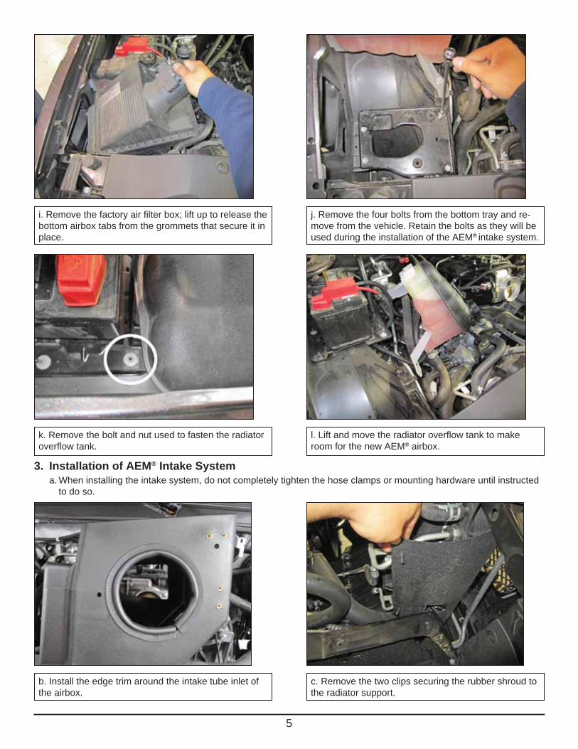
k. Remove the bolt and nut used to fasten the radiator overflow tank.
l. Lift and move the radiator overflow tank to make room for the new AEM® airbox.
3. Installation of AEM® Intake System a. When installing the intake system, do not completely tighten the hose clamps or mounting hardware until instructed to do so.
b. Install the edge trim around the intake tube inlet of the airbox.
c. Remove the two clips securing the rubber shroud to the radiator support.
i. Remove the factory air filter box; lift up to release the bottom airbox tabs from the grommets that secure it in place.
j. Remove the four bolts from the bottom tray and re-move from the vehicle. Retain the bolts as they will be used during the installation of the AEM® intake system.
6
e. Secure the airbox to the vehicle by securing the 4 factory bolts removed in step 2j.
d. Install the AEM® airbox into the engine bay where the bottom tray of the factory airbox was previously installed. Secure the rubber shroud to the airbox by snapping the clips into the holes of the airbox as shown.
f. Install the supplied 1/2” grommet into the filter minder bracket (32-3017).
g. Attach the filter minder bracket to the airbox using 2 of the supplied button head bolts.
7
l. Thread the shorter end of the rubber mount into the intake tube as shown.
k. Make note of the length of the rubber mount’s studs, one side is much shorter than the other.
i. Attach the 5/32” hose to the filter minder’s nipple and route the hose through the hole in the airbox.
j. Remove the mass airflow sensor from the factory airbox and install it in the AEM® intake tube using the supplied socket bolts.
h. Insert the filter minder into filter minder bracket.
m. Orient the bracket (32-3079) onto the rubber mount and secure with the supplied washer and nut.
8
n. Install the grommet in the intake tube. o. Install the coupler onto the throttle body.
p Install two hose clamps onto the coupler. q. Replace the overflow tank in its original location and fasten it with the factory nut and bolt that were removed in step 2k.
r. Remove the plastic clip attached to the upperradiator hose.
s. Flip the plastic clip around and position it on the up-per radiator hose as shown.
9
t. Reconnect the smaller hose to the plastic radiator clip.
u. Drill a 1/8” hole in the air filter lid in the location shown.
v. Install the 1/8” grommet in the hole drilled out in the previous step.
w. Install the 90° degree elbow into the grommet. To ease the installation of the elbow, you may use a small amount of soapy water.
x. Insert the filter adapter into the air filter; then install the large hose clamp over the filter neck.
y. Connect the filter minder’s 5/32” hose to the 90° elbow installed in the filter cap, then place the air filter in the airbox.
10
z. Route the intake tube under the coolant hoses and into the airbox hole. Then insert the intake tube end with the “AEM logo” into the coupler installed on the throttle body.
aa. Attach the intake tube bracket to the airbox using the supplied bolts and washers.
ab. Install the radiator hose clip into the threaded insert as shown.
ac. Orient and attach the air filter to the intake tube as shown.
ad. Secure the air filter assembly to the intake tube ensuring that the slot of the air filter neck aligns with the notch on the intake tube.
ae. Install the 3/8” straight connector onto one end of the 3/8” hose. Also slide the small hose clamps over each end of the hose.
11
ag. Insert the opposite end of the 3/8” hose into the grommet installed on the intake tube.
ah. Connect the MAF sensor harness to the mass sensor.
AEM® intake system installed
ai. Install the airbox lid and secure it with the supplied washers and bolts.
af. Attach the 3/8” hose to the metal tube that the fac-tory PCV line was originally attached to. Ensure that the PCV hose slides over the barb and is secured with the 5/8’ hose clamp (4093-3).
12
AEM Air Intake System Warranty PolicyAEM® warrants that its intake systems will last for the life of your vehicle. AEM will not honor this warranty due to mechani-cal damage (i.e. improper installation or fitment), damage from misuse, accidents or flying debris. AEM will not warrant its powder coating if the finish has been cleaned with a hydrocarbon-based solvent. The powder coating should only be cleaned with a mild soap and water solution. Proof of purchase of both the vehicle and AEM intake system is required for redemption of a warranty claim.
This warranty is limited to the repair or replacement of the AEM part. In no event shall this warranty exceed the original purchase price of the AEM part nor shall AEM be responsible for special, incidental or consequential damages or cost incurred due to the failure of this product. Warranty claims to AEM must be transportation prepaid and accompanied with dated proof of purchase. This warranty applies only to the original purchaser of product and is nontransferable. Improper use or installation, use for racing, accident, abuse, unauthorized repairs or alterations voids this warranty. AEM disclaims any liability for consequential damages due to breach of any written or implied warranty on all products manufactured by AEM. Warranty returns will only be accepted by AEM when accompanied by a valid Return Merchandise Authorization (RMA) number. Credit for defective products will be issued pending inspection. Product must be received by AEM within 30 days of the date RMA is issued.
4. Reassemble Vehicle a. Position the inlet pipes for the best fitment. Be sure that the pipes or any other components do not contact any part of the vehicle. Tighten the rubber mount, all bolts, and hose clamps. b. Check for proper hood clearance. Re-adjust pipes if necessary and re-tighten them. c. Inspect the engine bay for any loose tools and check that all fasteners that were moved or removed are properly tightened. d. Reconnect negative battery terminals and start engine. Let the vehicle idle for 3 minutes. Perform a final inspection before driving the vehicle.
5. Service and Maintenance a. It is recommended that you service your AEM® Dryflow™ filter every 20,000 miles for optimum performance. Use AEM Dryflow cleaning kit part # 21-110. b. Use aluminum polish to clean your polished AEM® intake tube. c. Use window cleaner to clean your powder coated AEM® intake tube. (NOTE: DO NOT USE aluminum polish on powder coated AEM intake tubes).