READ THIS FIRST: Read and follow all vehicle warnings and installation instructions before beginning installation. Wear safety glasses and use all safety precautions during installation. LISEZ CECI EN PREMIER: Lire et observer toutes les consignes de sécurité et les instructions avant de commencer l’installation. Durant l’installation, veiller à toujours porter des lunettes de protection et respecter les mesures de sécurité. LEA ESTO PRIMERO: Lea y siga todas las advertencias e instrucciones de instalación del vehículo antes de empezar la instalación. Use gafas de seguridad y todas las precauciones de seguridad durante la instalación. 118491-037 Rev. B 03/08/2010 Installation Instructions Directives de Montage Instrucciones de Instalación T-Connector Connecteur en T Conector en T Honda Pilot ENGLISH TOOLS REQUIRED: Trim Panel Remover, Test-probe 1. Open rear door and fold rear seat forward. Locate and open the storage compartment on the driver’s side of the cargo area d . 2. Locate the grey tow plug by opening the access panel inside of the storage compartment e . Insert the convertor box into the vehicle’s grey tow plug. 3. Locate the fuse panel in the rear cargo area on the driver’s side next to the rear seats that are in the folded position d . Open fuse compartment using trim panel remover. Insert relays and fuses as described below. – Kit #118253 - 2 relays and fuses as shown in Photo . – Kit #118491 - 1 relay and fuses as shown in Photo . 4. Locate vehicle fuse box in engine compartment on driver’s side. Insert fuses into positions as shown g . 5. Locate the large grey housing under the vehicle bumper on the driver’ side h . Remove protective cap, being careful not to break the locking tabs. Ensure that the mating surfaces are free of dirt. Plug towing harness into grey tow plug. Be careful not to damage the locking tabs and be sure that connectors are fully inserted with locking tabs in place. Route the T-Connector harness rearward to the back of the fascia of the bumper. e WARNING Route the wire being careful to avoid any hot pipes, heat shields, the fuel tank or any other points that may pinch or break the wire. 7. Secure 4-Flat/ 7-Way tow harness to hitch. Bracket not included. WARNING Secure the remainder of the T-Connector harness under the bumper with cable ties provided, being careful to avoid any areas that would cut or pinch the wire. WARNING All connections must be complete to function properly. Test and verify installation once installed. For initial test, reset vehicle electrical system by temporarily removing the key from the ignition. Test the installation with a test light or trailer. WARNING Overloading circuit can cause fires. DO NOT exceed lower of vehicle manufacturer rating or: • Max. stop/turn light: 2 per side (4.2 amps) • Max. tail lights: (7.5 amps) Read vehicle’s owners manual & instruction sheet for additional information. d g h Storage Compartment Compartiment de rangement Compartimiento de almacenamiento Fuse Compartment Compartiment à fusibles Compartimiento de fusibles 30 amp box fuse Boîtier à fusibles 30 ampères Caja de fusibles 30 amperios 20 amp fuse Fusible 20 ampères Fusible de 20 amperios 20 amp 20 ampères 20 amperios Empty Vide Vacío 7.5 amp 7,5 ampères 7.5 amperios Empty Vide Vacío 7.5 amp 7,5 ampères 7.5 amperios Relay Relais Relé 20 amp 20 ampères 20 amperios 118253 Harness C-1 C-1 C-2 C-2 118491 Harness Relay Relais Relé
Transcript
READ THIS FIRST:Read and follow all vehicle warnings and installation instructions before beginning installation. Wear safety glasses and use all safety precautions during installation.LISEz CECI En PREmIER: Lire et observer toutes les consignes de sécurité et les instructions avant de commencer l’installation. Durant l’installation, veiller à toujours porter des lunettes de protection et respecter les mesures de sécurité.LEA ESTO PRImERO: Lea y siga todas las advertencias e instrucciones de instalación del vehículo antes de empezar la instalación. Use gafas de seguridad y todas las precauciones de seguridad durante la instalación.
118491-037 Rev. B 03/08/2010
Installation InstructionsDirectives de montage
Instrucciones de Instalación
T-ConnectorConnecteur en TConector en T
Honda Pilot
ENGLISH
TOOLS REQUIRED: Trim Panel Remover, Test-probe1. Open rear door and fold rear seat forward.
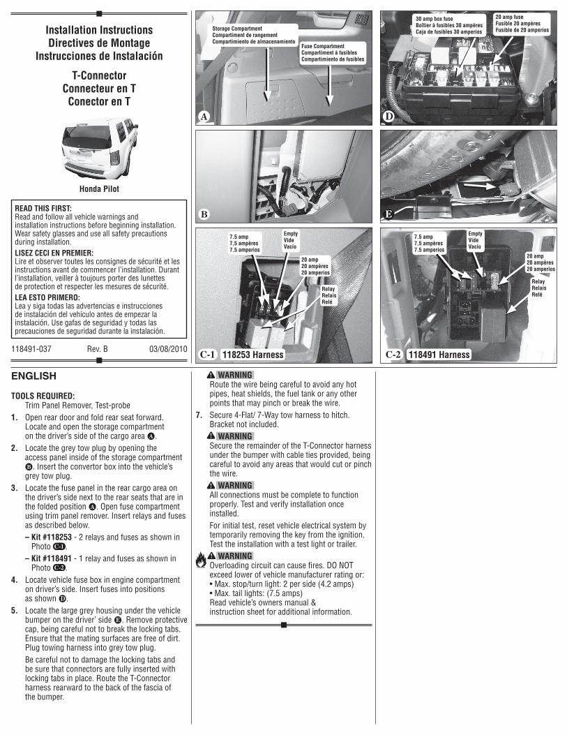
Locate and open the storage compartment on the driver’s side of the cargo area d.
2. Locate the grey tow plug by opening the access panel inside of the storage compartment e. Insert the convertor box into the vehicle’s grey tow plug.
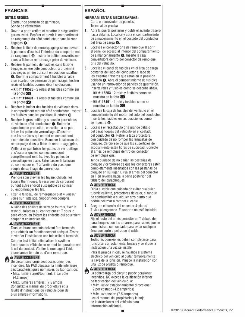
3. Locate the fuse panel in the rear cargo area on the driver’s side next to the rear seats that are in the folded position d. Open fuse compartment using trim panel remover. Insert relays and fuses as described below.
– Kit #118253 - 2 relays and fuses as shown in Photo .
– Kit #118491 - 1 relay and fuses as shown in Photo .
4. Locate vehicle fuse box in engine compartment on driver’s side. Insert fuses into positions as shown g.
5. Locate the large grey housing under the vehicle bumper on the driver’ side h. Remove protective cap, being careful not to break the locking tabs. Ensure that the mating surfaces are free of dirt. Plug towing harness into grey tow plug.
Be careful not to damage the locking tabs and be sure that connectors are fully inserted with locking tabs in place. Route the T-Connector harness rearward to the back of the fascia of the bumper.
e
WARnInG Route the wire being careful to avoid any hot pipes, heat shields, the fuel tank or any other points that may pinch or break the wire.
7. Secure 4-Flat/ 7-Way tow harness to hitch. Bracket not included.
WARnInG Secure the remainder of the T-Connector harness
under the bumper with cable ties provided, being careful to avoid any areas that would cut or pinch the wire.
WARnInG All connections must be complete to function
properly. Test and verify installation once installed.
For initial test, reset vehicle electrical system by temporarily removing the key from the ignition. Test the installation with a test light or trailer.
WARnInG Overloading circuit can cause fires. DO NOT
exceed lower of vehicle manufacturer rating or: • Max. stop/turn light: 2 per side (4.2 amps) • Max. tail lights: (7.5 amps) Read vehicle’s owners manual & instruction sheet for additional information.
d g
h
Storage CompartmentCompartiment de rangementCompartimiento de almacenamiento
Fuse CompartmentCompartiment à fusiblesCompartimiento de fusibles
30 amp box fuseBoîtier à fusibles 30 ampèresCaja de fusibles 30 amperios
20 amp fuse Fusible 20 ampèresFusible de 20 amperios
20 amp20 ampères20 amperios
EmptyVideVacío
7.5 amp7,5 ampères7.5 amperios
EmptyVideVacío
7.5 amp7,5 ampères7.5 amperios
RelayRelaisRelé
20 amp20 ampères20 amperios
118253 Harness
C-1
C-1
C-2
C-2 118491 Harness
RelayRelaisRelé
FRANCAIS
OUTILS REQUIS: Écarteur de panneau de garnisage,
Sonde de vérification1. Ouvrir la porte arrière et rabattre le siège arrière
par en avant. Repérer et ouvrir le compartiment de rangement du côté conducteur dans la zone bagages d.
2. Repérer la fiche de remorquage grise en ouvrant la panneau d’accès à l’intérieur du compartiment de rangement e. Insérer le boîtier convertisseur dans la fiche de remorquage grise du véhicule.
3. Repérer le panneau de fusibles dans la zone bagages arrière côté conducteur, à proximité des sièges arrière qui sont en position rabattue d. Ouvrir le compartiment à fusibles à l’aide d’un écarteur de panneau de garnissage. Insérer relais et fusibles comme décrit ci-dessous.
– Kit n° 118523 - 2 relais et fusibles comme sur la photo .
– Kit n° 118491 - 1 relais et fusibles comme sur la photo .
4. Repérer le boîtier des fusibles du véhicule dans le compartiment moteur côté conducteur. Insérer les fusibles dans les positions illustrées g.
5. Repérer le gros boîtier gris sous le pare-chocs du véhicule côté conducteur h. Retirer le capuchon de protection, en veillant à ne pas briser les pattes de verrouillage. S’assurer que les surfaces qui entrent en contact sont exemptes de poussière. Brancher le faisceau de remorquage dans la fiche de remorquage grise.
Veiller à ne pas briser les pattes de verrouillage et s’assurer que les connecteurs sont complètement rentrés, avec les pattes de verrouillage en place. Faire passer le faisceau du connecteur en T à l’arrière du plastique souple de carénage du pare-chocs.
AVERTISSEmEnT Prendre soin d’éviter les tuyaux chauds, les
écrans thermiques, le réservoir de carburant ou tout autre endroit susceptible de coincer ou endommager les fils.
7. Fixer le faisceau de remorquage plat 4 voies/7 voies sur l’attelage. Support non compris.
AVERTISSEmEnT À l’aide des colliers de serrage fournis, fixer le
reste du faisceau du connecteur en T sous le pare-chocs, en évitant les endroits qui pourraient couper et coincer les fils.
AVERTISSEmEnT Tous les branchements doivent être terminés
pour obtenir un fonctionnement adéquat. Tester et vérifier l’installation une fois celle-ci terminée.
Comme test initial, réinitialiser le système électrique du véhicule en retirant temporairement la clé du contact. Vérifier le montage à l’aide d’une lampe témoin ou d’une remorque.
AVERTISSEmEnT Un circuit surchargé peut occasionner des
incendies. NE PAS dépasser la limite inférieure des caractéristiques nominales du fabricant ou: • Max. lumière arrêt/tournant: 2 par côté
(4,2 amps) • Max. lumières arrières: (7,5 amps)
Consultez le manuel du propriétaire et la feuille d’instructions du véhicule pour de plus amples informations.
ESPAÑOL
HERRAMIENTAS NECESSARIAS: Corte el removedor de paneles, Terminal de prueba1. Abra la puerta posterior y doble el asiento trasero
hacia delante. Localice y abra el compartimiento de almacenamiento en el costado del conductor del área de carga d.
2. Localice el conector gris de remolque al abrir el panel de acceso al interior del compartimiento de almancenamiento e. Inserte la caja convertidora dentro del conector de remolque gris del vehículo.
3. Localice el panel de fusibles en el área de carga posterior del lado del conductor al lado de los asientos traseros que están en la posición doblada d. Abra el compartimiento de fusibles usando un removedor de paneles de guarnición. Inserte relés y fusibles como se describe abajo.
– Kit #118253 - 2 relés y fusibles como se muestra en la foto .
– Kit #118491 - 1 relé y fusibles como se muestra en la foto .
4. Localice la caja de fusibles del vehículo en el compartimiento del motor del lado del conductor. Inserte los fusibles en las posiciones como se muestra g.
5. Localice el receptáculo gris grande debajo del parachoques del vehículo en el costado del conductor h. Retire la tapa protectora, con cuidado de no romper las lengüetas de bloqueo. Cerciórese de que las superficies de acoplamiento estén libres de suciedad. Conecte el arnés de remolque dentro del conector de remolque gris.
Tenga cuidado de no dañar las pestañas de bloqueo y cerciórese de que los conectores estén completamente insertados con las pestañas de bloqueo en su lugar. Dirija el arnés del conector en T en reversa hacia la parte posterior del tablero del parachoques.
ADVERTEnCIA Dirija el cable con cuidado de evitar cualquier
tubería caliente, protectores de calor, el tanque de combustible o cualquier otro punto que podría pellizcar o romper el cable.
7. Asegure el harnés del conector 4-plano/ 7-vías al enganche. El soporte no está incluido.
ADVERTEnCIA Fije el resto del arnés conector en T debajo del
parachoques con los amarres para cables que se suministran, con cuidado para evitar cualquier área que corte o pellizque el cable.
ADVERTEnCIA Todas las conexiones deben completarse para
funcionar correctamente. Ensaye y verifique la instalación una vez se instale.
Para la prueba inicial, reinicialice el sistema eléctrico del vehículo al quitar temporalmente la llave de la ignición. Pruebe la instalación con una luz de prueba o remolque.
ADVERTEnCIA La sobrecarga del circuito puede ocasionar
incendios. NO exceda la calificación inferior de fabricación del vehículo, o: • Máx. luz de estacionamiento/ direccional:
2 por costado (4.2 amperios) • Máx. luz trasera: (7.5 amperios) Lea el manual del propietario y la hoja
de instrucciones del vehículo para información adicional.


![3 1. [20 ]75. 28 récente version. C1 A5€¦ · tb-vw sold separately vendu sÉparÉment male t-harness ignition plug connecteur d’ignition mle du t-harnais female t-harness ignition](https://static.documents.pub/doc/80x56/605b3586a399a25b9934ea45/3-1-20-75-28-rcente-version-c1-a5-tb-vw-sold-separately-vendu-sparment.jpg)


