Thank you for purchasing a Non-Return Flue Check Valve for your PVC/CPVC common vent application.
If You Need Service Contact your local dealer/distributor, or call Rinnai Customer Care at 1-800-621-9419 Monday to Friday between 8 AM to 8 PM ET.
To The Installer This manual is intended for the installer and is
designed for licensed installers who should have skills such as:
Gas sizing
Connecting gas lines, water lines, valves, and electricity
Knowledge of applicable national, state, and local codes
Installing venting through a wall or roof
Training in installation of tankless water heaters. Training on Rinnai Tankless Water Heaters is accessible at www.trainingevents.rinnai.us
A licensed installer must test the PVC/CPVC common vent system for leaks before use.
The installation must conform to the Rinnai Tankless Water Heater Installation and Operation Manual that is shipped with the unit, local codes, or in the absence of local codes, with the National Fuel Gas Code, ANSI Z223.1/NFPA 54.
Read all instructions contained in this manual before installing the Non-Return Flue Check Valve; the valve must be installed according to the exact instructions in this manual.
Proper installation is the responsibility of the installer.
When installation is complete, give all manuals related to the common venting installation (including this manual and the Rinnai Water Heater Installation and Operation Manual) directly to the consumer. The manuals should be stored in a readily accessible location for future reference.
To The Consumer
Keep this manual for future reference. Be sure your PVC/CPVC common vent system,
including the Non-Return Flue Check Valve, is installed by a licensed installer.
Welcome
Welcome Page
If You Need Service 2
To The Installer 2
To The Consumer 2
1. Safety 3
1.1 Safety Symbols 3
2. About PVC/CPVC Common Venting 4
2.1 Venting Guidelines 4
2.2 Derate and Total BTU 5
2.3 High Altitude Installations 5
2.4 Items Included 6
2.5 Items Needed For Installation 6
2.6 Items Not Required 6
2.7 About the Non-Return Flue Check Valve 6
3. Install the Venting 7
Venting Installation Sequence 7
For The Installer 7
3.1 Choose the Installation Location 8
3.2 Install Check Valve to Water Heater 9
3.3 Assemble the Header 12
3.4 Connect the Venting 14
3.5 Terminate the Venting 15
3.6 Set DIP Switches 18
3.7 Connect Cables 19
3.8 Post Installation Checklist 19
Contents
This manual provides installation instructions for PVC/CPVC common venting with a non-return flue check valve and is a supplement to the Installation and Operations Manual supplied with the Rinnai Tankless Water Heater. Common venting with PVC and CPVC must satisfy all the requirements of the Installation and Operations Manual, as well as the requirements in this manual.
For detailed information on the Rinnai Tankless Water Heater, including installation instructions, refer to the Tankless Water Heater Installation and Operation Manual or view an online version at rinnai.us.
1. Safety READ ALL INSTRUCTIONS BEFORE INSTALLATION
Installations must comply with local requirements and with the National Fuel Gas Code, ANSI Z223.1/NFPA 54 for U.S. installations.
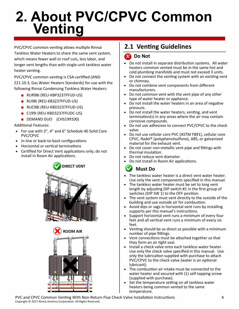
Installations are certified for Direct Vent applications only. DO NOT install in Room Air applications.
Use only 3” and 4” Schedule 40 Solid Core PVC/CPVC. DO NOT use any other type of venting material, including cellular core PVC (ASTM F891), cellular core CPVC, Radel® (polyphenolsulfone), ABS, or galvanized material.
Use only the materials listed in this section for vent, air intake pipe, and fittings. Failure to comply with this warning could result in property damage, personal injury, or death.
DO NOT operate the unit until venting is completely installed and all solvents and glues have bonded. Failure to comply with this warning could result in property damage, personal injury, or death.
DO NOT slope the combustion air pipe toward unit. Failure to comply with this warning could result in property damage, personal injury, or death.
DO NOT apply PVC/CPVC glues, solvents, or cleaners to the tankless water heater’s intake or exhaust gasket connections. Failure to correctly assemble the components according to these instructions may result in property damage, personal injury, or death.
PVC/CPVC common venting cannot be used if the following conditions exist:
The tankless water heater is installed in a recirculation system and the thermostat setting is greater than 150 F (65.5 C).
The tankless water heater is used in a combination domestic water and space heating application that requires a thermostat setting greater than 150 F (65.5 C).
PVC/CPVC common venting is not approved for use in Canada.
WARNING
If the information in these instructions is not followed exactly, a fire or explosion may result causing property damage, personal injury, or death.
Do not store or use gasoline or other flammable vapors and liquids in the vicinity of this or any other appliance.
WHAT TO DO IF YOU SMELL GAS: Do not try to light any appliance. Do not touch any electrical switch; do not use
any phone in your building. Immediately call your gas supplier from a
neighbor’s phone. Follow the gas supplier’s instructions.
If you cannot reach your gas supplier, call the fire department.
Installation and service must be performed by a qualified installer, service agency or the gas supplier.
The warning signs in this manual are here to prevent injury to you and others. Please follow them explicitly.
WARNING
1.1 Safety Symbols
Indicates an imminently hazardous situation which, if not avoided, will result in personal injury or death.
Indicates a potentially hazardous situation which, if not avoided, could result in personal injury or death.
Indicates a potentially hazardous situation which, if not avoided, could result in minor or moderate injury. It may also be used to alert against unsafe practices.
Safety alert symbol. Alerts you to potential hazards that can kill or hurt you and others.
DANGER
CAUTION
WARNING
This manual contains the following important safety symbols. Always read and obey all safety messages.
IMPORTANT
The Non-Return Flue Check Valve (Rinnai Part # 790111) is referred to as “check valve” throughout the remainder of this manual.
Do not install in separate distribution systems. All water heaters common vented must be in the same hot and cold plumbing manifolds and must not exceed 3 units.
Do not connect the venting system with an existing vent or chimney.
Do not combine vent components from different manufacturers.
Do not common vent with the vent pipe of any other type of water heater or appliance.
Do not install the water heaters in an area of negative pressure.
Do not install the water heaters, venting, and vent termination(s) in any areas where the air may contain corrosive compounds.
Do not use adhesives to connect PVC/CPVC to the check valve.
Do not use cellular core PVC (ASTM F891), cellular core CPVC, Radel® (polyphenolsulfone), ABS, or galvanized material for the exhaust vent.
Do not cover non-metallic vent pipe and fittings with thermal insulation.
Do not reduce vent diameter. Do not install in Room Air applications.
Must Do
The tankless water heater is a direct vent water heater. Use only the vent components specified in this manual.
The tankless water heater must be set to long vent length by adjusting DIP switch #1 in the first group of switches (DIP SW 1) to the OFF position.
The vent system must vent directly to the outside of the building and use outside air for combustion.
Avoid dips or sags in horizontal vent runs by installing supports per this manual’s instructions.
Support horizontal vent runs a minimum of every four feet and all vertical vent runs a minimum of every six feet.
Venting should be as direct as possible with a minimum number of pipe fittings.
Vent connections must be attached together so that they form an air tight seal.
Install a check valve onto each tankless water heater. Use only the check valve specified in this manual. Use only the lubrication supplied with purchase to attach PVC/CPVC to the check valve (water is an optional lubricant).
The combustion air intake must be connected to the water heater and secured with (1) self-tapping screw (supplied with purchase).
Set the temperature setting on all tankless water heaters being common vented to the same temperature.
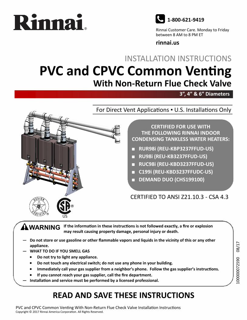
PVC/CPVC common venting allows multiple Rinnai
Tankless Water Heaters to share the same vent system,
which means fewer wall or roof cuts, less labor, and
longer vent lengths than with single-unit tankless water
heater venting.
PVC/CPVC common venting is CSA-certified (ANSI
Z21.10.3, Gas Water Heaters Standards) for use with the
following Rinnai Condensing Tankless Water Heaters:
■ RUR98i (REU-KBP3237FFUD-US)
■ RU98i (REU-KB3237FFUD-US)
■ RUC98i (REU-KBD3237FFUD-US)
■ C199i (REU-KBD3237FFUDC-US)
■ DEMAND DUO (CHS199100)
Additional Features:
For use with 3”, 4” and 6” Schedule 40 Solid Core PVC/CPVC
In-line or back-to-back configurations Horizontal or vertical terminations Certified for Direct Vent applications only; do not
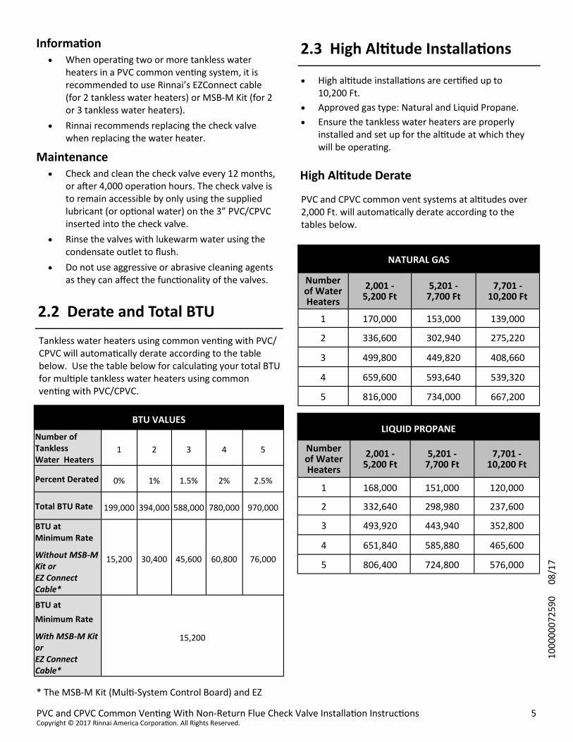
High altitude installations are certified up to 10,200 Ft.
Approved gas type: Natural and Liquid Propane.
Ensure the tankless water heaters are properly installed and set up for the altitude at which they will be operating.
PVC and CPVC common vent systems at altitudes over 2,000 Ft. will automatically derate according to the tables below.
High Altitude Derate
Tankless water heaters using common venting with PVC/CPVC will automatically derate according to the table below. Use the table below for calculating your total BTU for multiple tankless water heaters using common venting with PVC/CPVC.
* The MSB-M Kit (Multi-System Control Board) and EZ
2.2 Derate and Total BTU
BTU VALUES
Number of Tankless Water Heaters
1 2 3 4 5
Percent Derated 0% 1% 1.5% 2% 2.5%
Total BTU Rate 199,000 394,000 588,000 780,000 970,000
BTU at Minimum Rate
Without MSB-M Kit or EZ Connect Cable*
15,200 30,400 45,600 60,800 76,000
BTU at
Minimum Rate
With MSB-M Kit or EZ Connect Cable*
15,200
2.3 High Altitude Installations Information When operating two or more tankless water
heaters in a PVC common venting system, it is recommended to use Rinnai’s EZConnect cable (for 2 tankless water heaters) or MSB-M Kit (for 2 or 3 tankless water heaters).
Rinnai recommends replacing the check valve when replacing the water heater.
Maintenance Check and clean the check valve every 12 months,
or after 4,000 operation hours. The check valve is to remain accessible by only using the supplied lubricant (or optional water) on the 3” PVC/CPVC inserted into the check valve.
Rinse the valves with lukewarm water using the condensate outlet to flush.
Do not use aggressive or abrasive cleaning agents as they can affect the functionality of the valves.
Open the package and verify the following contents are included. If any items are missing or damaged, contact your local dealer/distributor or Rinnai Customer Care at 1-800-621-9419.
Ubbink Non-Return Flue Check Valve
(Rinnai Part #: 790111)
Required for each tankless water heater in the PVC/CPVC common vent system
2.5 Items Needed For Installation (Not Included)
Hammer drill with concrete bits
Concrete wall hangers
PVC/CPVC Vent Screen Guard (shown below)
Rinnai recommends the installation of a PVC/CPVC vent screen for both the intake and exhaust vents. The PVC/CPVC vent screen prevents rodents, birds and other outdoor hazards from entering the terminations.
2.6 Items Not Required But May Be Useful
Field Supplied PVC/CPVC
Vent Screen Guard
Building Wall
3” PVC/CPVC Mount
Check Valve Adapter
Vent System Lubricant
For seal ring lubrication
(6) Self-Tapping Screws
(5) screws for installation and (1) extra replacement screw
Installation Instructions (this manual)
2.7 About the Non-Return Flue Check Valve
The Non-Return Flue Check Valve prevents backflow of exhaust gases into idle tankless water heaters.
Requirements:
Must be installed on each tankless water heater that is a part of the PVC and CPVC common vent system.
For Direct Vent applications only. Intended for exhaust flow only. Intake air must be
plumbed separately to the intake side of the tankless water heater.
Accepts 3” PVC/CPVC, 4” & 6” PVC/CPVC system sizes achieved through the use of reducers attached to 3” PVC/CPVC.
Part Name
Non-Return Flue Check Valve (For Direct Vent Applications Only)
FOR THE INSTALLER Installer Qualifications: A licensed installer must install, inspect and test the PVC/CPVC common venting before use.
The installer should have skills such as: Gas sizing; Connecting gas lines, water lines, valves, and electricity; Knowledge of applicable national, state, and local codes; Installing venting through a wall or roof; and training in installation of tankless water heaters. Training for Rinnai Tankless Water Heaters is accessible online at www.trainingevents.rinnai.us.
DANGER
3. Install the Venting
Tankless water heaters with PVC/CPVC venting must be configured with intake air and exhaust vents using piping and methods described in this section. Each water heater must have its own intake and vent. DO NOT common vent with any other appliance using this method. Inspect finished vent and intake air piping thoroughly to ensure all are air tight and comply with the instructions provided and with all requirements of applicable codes. Failure to provide a properly installed vent and air system will cause personal injury or death.
Combustion Air Intake - The combustion air intake termination fitting must be installed with the clearances and geometry relative to the exhaust (vent) depicted in this manual to ensure that flue products do not enter the combustion air intake. Contaminated intake air will damage the water heater, resulting in possible property damage, personal injury, or death.
Exhaust - The exhaust (vent) termination fitting must be installed with the clearances and geometry relative to the combustion air pipe as depicted in this manual to ensure that flue products do not enter the combustion air intake.
The installation must conform with local codes or, in the absence of local codes, with the National Fuel Gas Code, ANSI Z223.1/NFPA 54, or the Natural Gas and Propane Installation Code, CSA B149.1.
DO NOT use cellular core PVC (ASTM F891), cellular core CPVC, Radel® (polyphenolsulfone), ABS, or galvanized material for the exhaust vent.
Vents MUST be of Schedule 40 Solid Core pipes
ONLY.
Use only the materials listed in this manual for vent, combustion air intake pipe, and fittings. Failure to comply with this warning could result in property damage, personal injury, or death.
If used, a masonry chimney can ONLY be used as a CHIMINEY CHASE for the exhaust and combustion air intake pipes. The exhaust and air piping must be installed as instructed in this manual. The chimney chase must be used only for the Rinnai Tankless Water Heater’s vent chase. NO OTHER appliance or fireplace can be connected to the chimney chase. Exhaust and air piping materials must comply with this instruction. The chimney chase must be fitted with a sealed access opening to facilitate interior inspection. The chimney chase (and liner, if installed) to be inspected annually for any degradation. Failure to comply could result in property damage, personal injury, or death.
WARNING
Listed below is the sequence for installing PVC/CPVC common venting.
Step 1: Choose the Installation Location
Step 2: Install the Check Valves
Step 3: Assemble the Header
Step 4: Connect the Venting
Step 5: Terminate the Venting
Step 6: Set DIP Switches
Step 7: Connect the Cables
Step 8: Post Installation Checklist
Improper installation of PVC/CPVC venting components, or failure to follow all installation instructions, can result in serious injury.
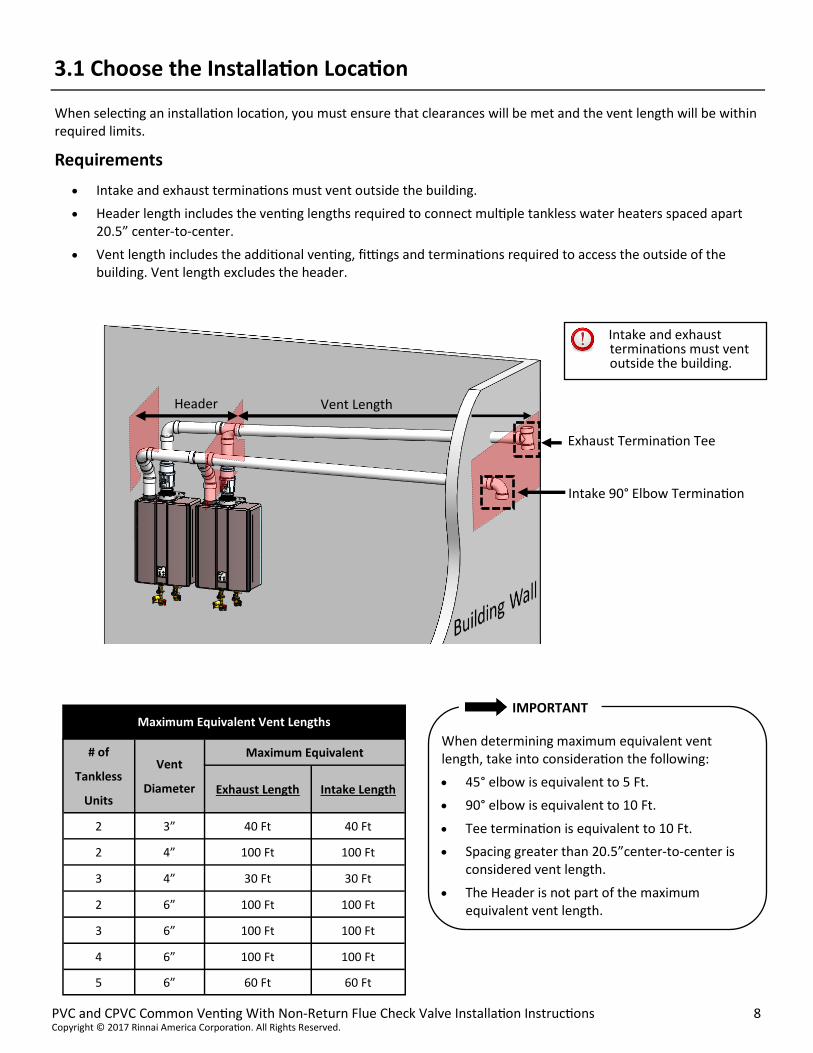
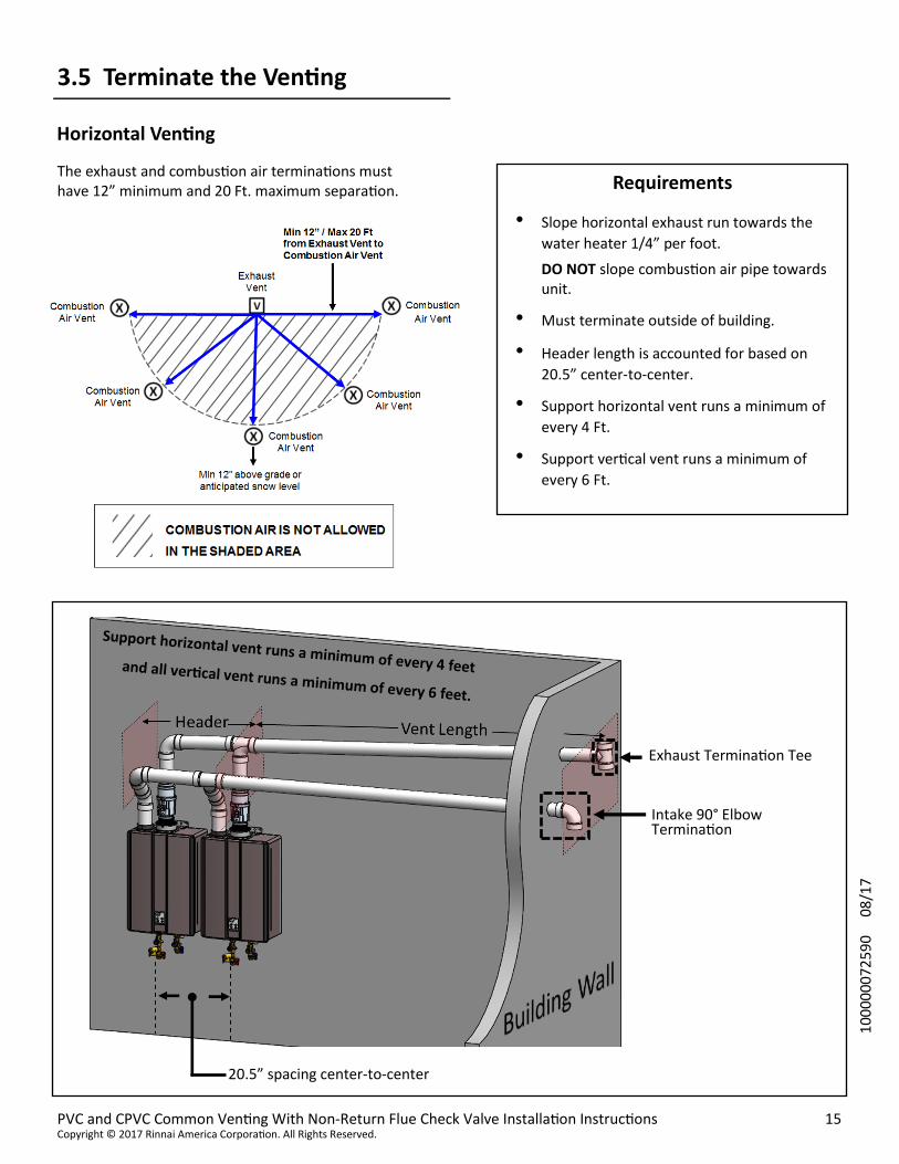
When selecting an installation location, you must ensure that clearances will be met and the vent length will be within required limits.
Requirements
Intake and exhaust terminations must vent outside the building.
Header length includes the venting lengths required to connect multiple tankless water heaters spaced apart 20.5” center-to-center.
Vent length includes the additional venting, fittings and terminations required to access the outside of the building. Vent length excludes the header.
Header Vent Length
3.1 Choose the Installation Location
Intake 90° Elbow Termination
Exhaust Termination Tee
Intake and exhaust terminations must vent outside the building.
IMPORTANT
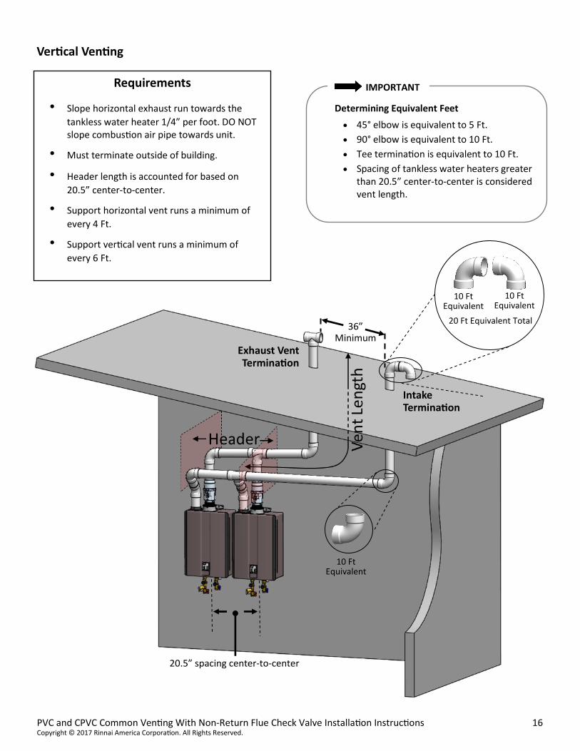
When determining maximum equivalent vent length, take into consideration the following:
45° elbow is equivalent to 5 Ft.
90° elbow is equivalent to 10 Ft.
Tee termination is equivalent to 10 Ft.
Spacing greater than 20.5”center-to-center is considered vent length.
The Header is not part of the maximum equivalent vent length.
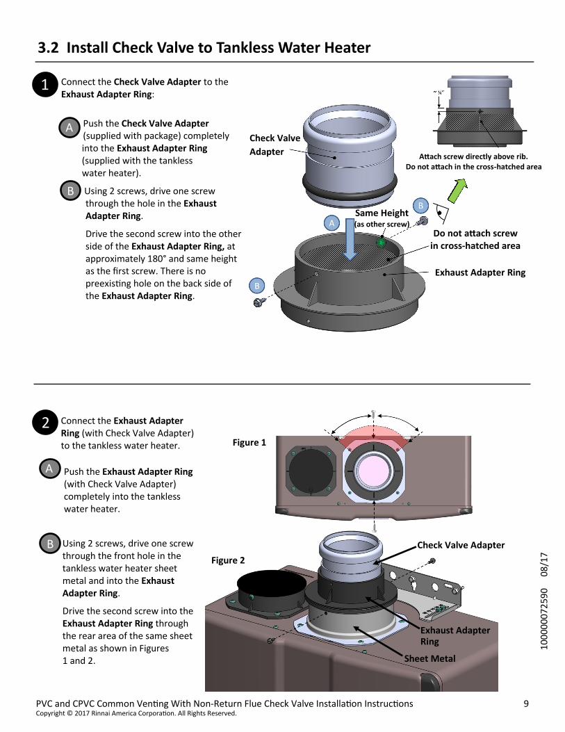
Connect the Check Valve Adapter to the Exhaust Adapter Ring:
Push the Check Valve Adapter (supplied with package) completely into the Exhaust Adapter Ring (supplied with the tankless water heater).
Using 2 screws, drive one screw through the hole in the Exhaust Adapter Ring.
Drive the second screw into the other side of the Exhaust Adapter Ring, at approximately 180° and same height as the first screw. There is no preexisting hole on the back side of the Exhaust Adapter Ring.
Connect the Exhaust Adapter Ring (with Check Valve Adapter) to the tankless water heater.
Using 2 screws, drive one screw through the front hole in the tankless water heater sheet metal and into the Exhaust Adapter Ring.
Drive the second screw into the Exhaust Adapter Ring through the rear area of the same sheet metal as shown in Figures 1 and 2.
Push the Exhaust Adapter Ring (with Check Valve Adapter) completely into the tankless water heater.
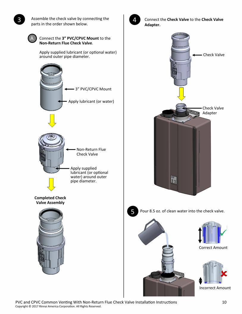
DO NOT use adhesives on the PVC/CPVC connection to the check valve. Use the supplied lubricant (or optional water). Adhesives will damage the check valve, and/or eliminate serviceability to the check valve.
WARNING
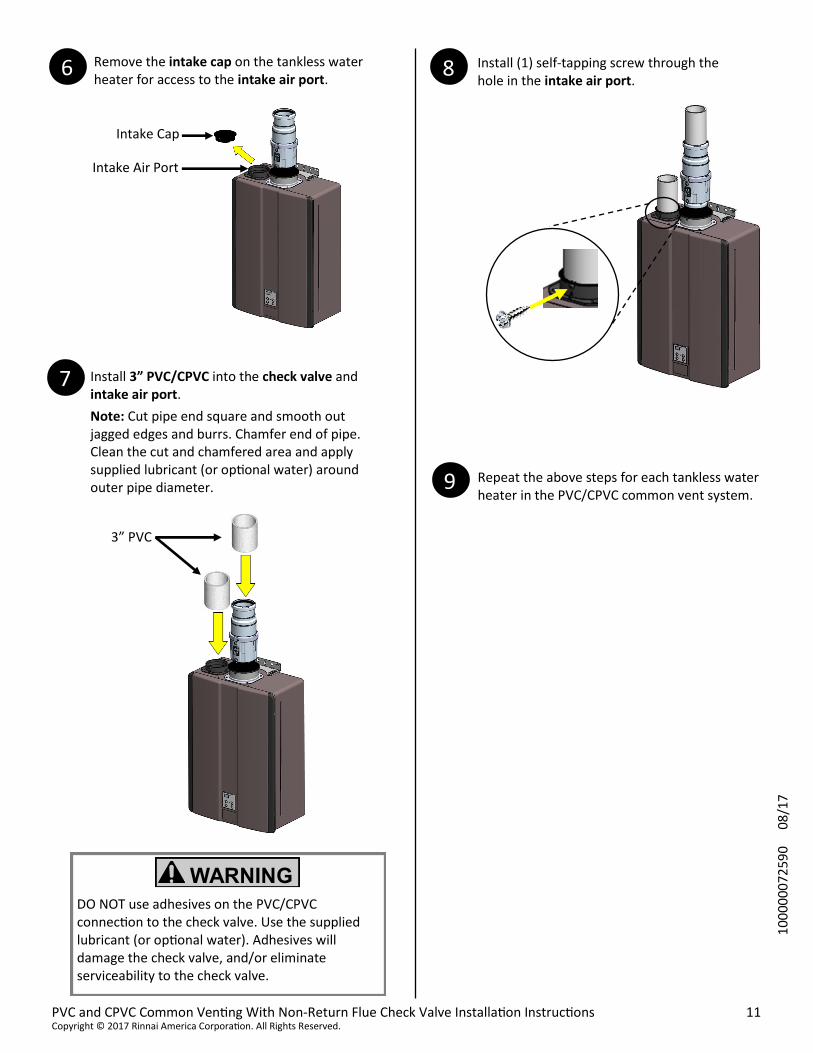
Remove the intake cap on the tankless water heater for access to the intake air port.
Install 3” PVC/CPVC into the check valve and intake air port.
Note: Cut pipe end square and smooth out jagged edges and burrs. Chamfer end of pipe. Clean the cut and chamfered area and apply supplied lubricant (or optional water) around outer pipe diameter.
Repeat the above steps for each tankless water heater in the PVC/CPVC common vent system.
3” PVC
Intake Cap
Intake Air Port
Install (1) self-tapping screw through the hole in the intake air port.
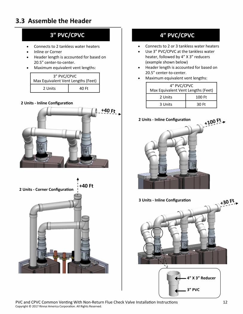
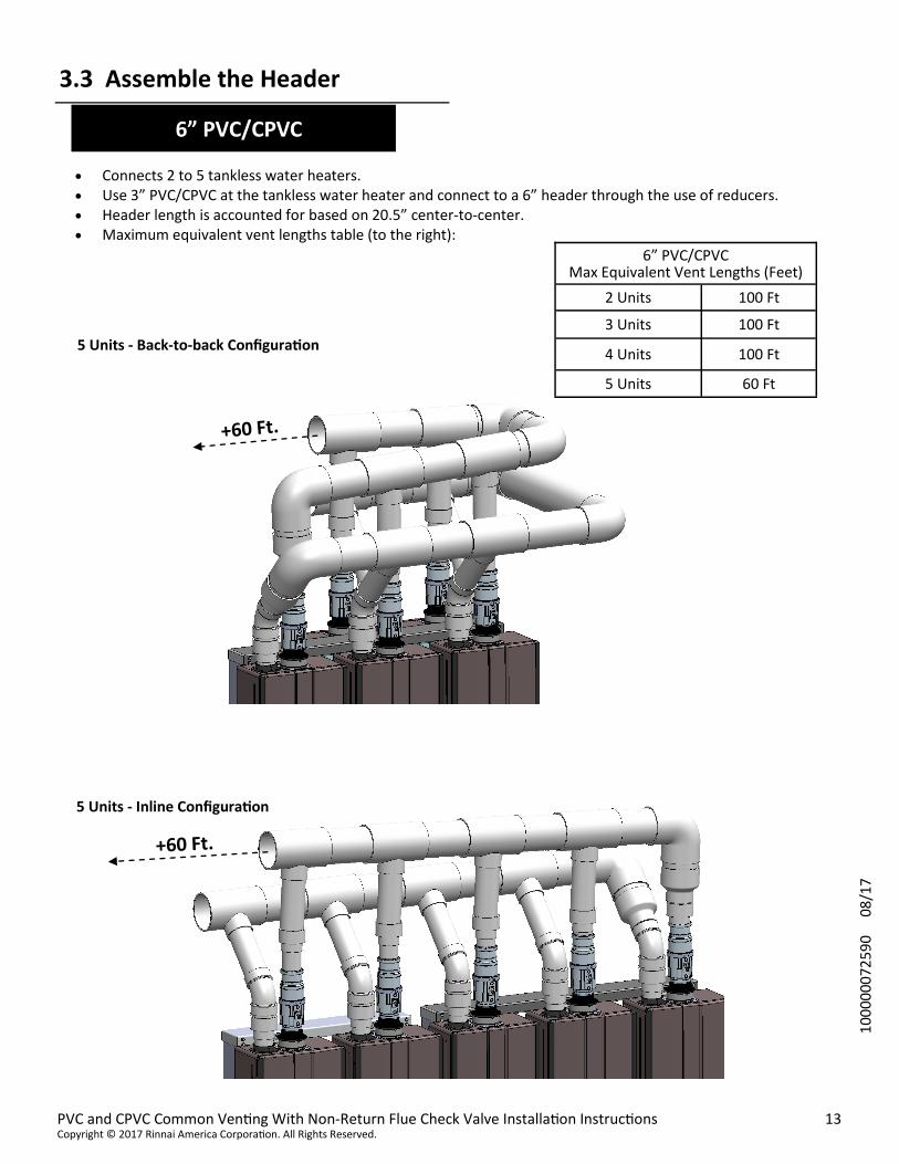
Connects 2 to 5 tankless water heaters. Use 3” PVC/CPVC at the tankless water heater and connect to a 6” header through the use of reducers. Header length is accounted for based on 20.5” center-to-center. Maximum equivalent vent lengths table (to the right):
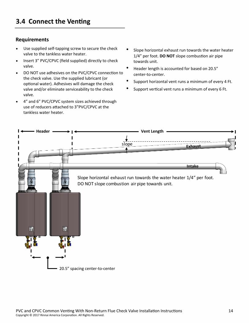
Use supplied self-tapping screw to secure the check valve to the tankless water heater.
Insert 3” PVC/CPVC (field supplied) directly to check valve.
DO NOT use adhesives on the PVC/CPVC connection to the check valve. Use the supplied lubricant (or optional water). Adhesives will damage the check valve and/or eliminate serviceability to the check valve.
4” and 6” PVC/CPVC system sizes achieved through use of reducers attached to 3”PVC/CPVC at the tankless water heater.
• Slope horizontal exhaust run towards the water heater
1/4” per foot. DO NOT slope combustion air pipe towards unit.
• Header length is accounted for based on 20.5”
center-to-center.
• Support horizontal vent runs a minimum of every 4 Ft.
• Support vertical vent runs a minimum of every 6 Ft.
Requirements
3.4 Connect the Venting
Header Vent Length
slope
Slope horizontal exhaust run towards the water heater 1/4” per foot. DO NOT slope combustion air pipe towards unit.
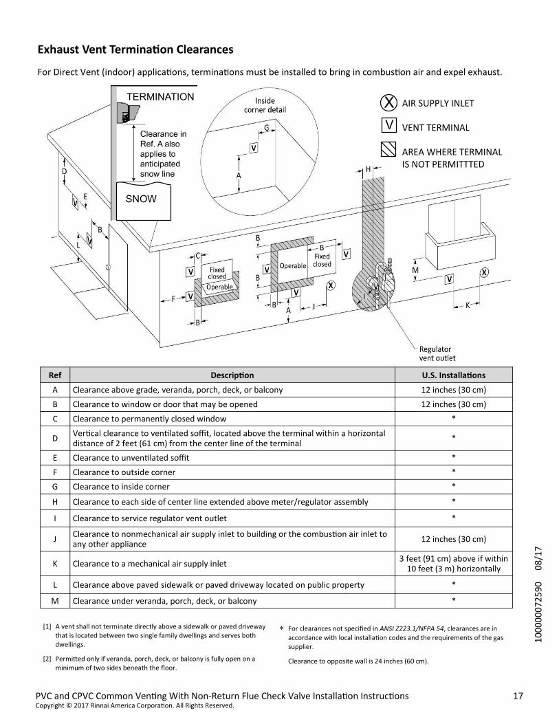
For Direct Vent (indoor) applications, terminations must be installed to bring in combustion air and expel exhaust.
[1] A vent shall not terminate directly above a sidewalk or paved driveway that is located between two single family dwellings and serves both dwellings.
[2] Permitted only if veranda, porch, deck, or balcony is fully open on a minimum of two sides beneath the floor.
For clearances not specified in ANSI Z223.1/NFPA 54, clearances are in accordance with local installation codes and the requirements of the gas supplier.
Clearance to opposite wall is 24 inches (60 cm).
Ref Description U.S. Installations
A Clearance above grade, veranda, porch, deck, or balcony 12 inches (30 cm)
B Clearance to window or door that may be opened 12 inches (30 cm)
C Clearance to permanently closed window *
D Vertical clearance to ventilated soffit, located above the terminal within a horizontal distance of 2 feet (61 cm) from the center line of the terminal
*
E Clearance to unventilated soffit *
F Clearance to outside corner *
G Clearance to inside corner *
H Clearance to each side of center line extended above meter/regulator assembly *
I Clearance to service regulator vent outlet *
J Clearance to nonmechanical air supply inlet to building or the combustion air inlet to any other appliance
12 inches (30 cm)
K Clearance to a mechanical air supply inlet 3 feet (91 cm) above if within
10 feet (3 m) horizontally
L Clearance above paved sidewalk or paved driveway located on public property *
M Clearance under veranda, porch, deck, or balcony *
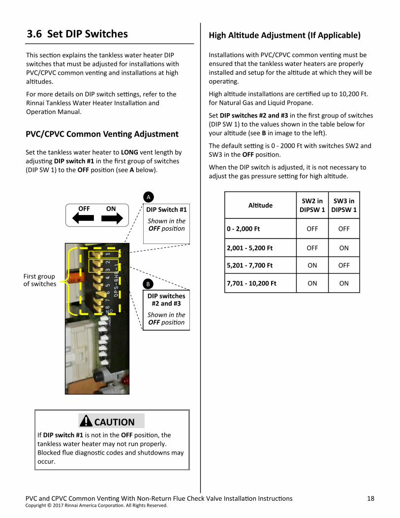
Installations with PVC/CPVC common venting must be ensured that the tankless water heaters are properly installed and setup for the altitude at which they will be operating.
High altitude installations are certified up to 10,200 Ft. for Natural Gas and Liquid Propane.
Set DIP switches #2 and #3 in the first group of switches (DIP SW 1) to the values shown in the table below for your altitude (see B in image to the left).
The default setting is 0 - 2000 Ft with switches SW2 and SW3 in the OFF position.
When the DIP switch is adjusted, it is not necessary to adjust the gas pressure setting for high altitude.
3.6 Set DIP Switches
This section explains the tankless water heater DIP switches that must be adjusted for installations with PVC/CPVC common venting and installations at high altitudes.
For more details on DIP switch settings, refer to the Rinnai Tankless Water Heater Installation and Operation Manual.
PVC/CPVC Common Venting Adjustment
Set the tankless water heater to LONG vent length by adjusting DIP switch #1 in the first group of switches (DIP SW 1) to the OFF position (see A below).
High Altitude Adjustment (If Applicable)
CAUTION
If DIP switch #1 is not in the OFF position, the tankless water heater may not run properly. Blocked flue diagnostic codes and shutdowns may occur.
Reference the Rinnai Water Heater Installation and Operation Manual for proper installation of the Rinnai Tankless Water Heaters.
The installation conforms with local codes or, in the absence of local codes, with the National Fuel Gas Code, ANSI Z223.1/NFPA 54, or the Natural Gas and Propane Installation Code, CSA B149.1.
Verify that only the following tankless water heater models are using the PVC/CPVC common vent system: RUR98i (REU-KBP3237FFUD-US) RU98i (REU-KB3237FFUD-US) RUC98i (REU-KBD3237FFUD-US) C199i (REU-KBD3237FFUDC-US) DEMAND DUO (CHS199100)
Ensure you have used the correct venting products and that you have completely followed the installation instructions in this manual.
Clearances from the tankless water heater units are met.
Clearances from the exhaust termination(s) and the combustion air termination(s) are met.
The vent system does not exceed the maximum equivalent length allowed.
Intake and exhaust terminations are vented outside the building.
Horizontal vent runs are installed with supports to avoid dips or sags.
All PVC/CPVC fittings are glued.
PVC/CPVC is NOT glued to the check valve.
DIP switch #1 in the first group of switches (DIP SW 1) is in the OFF position for each tankless water heater.
For high altitude installations: Verify the appropriate DIP switch settings are selected for the altitude/elevation of the installation location.
If utilizing an MSB-M Kit or EZConnect cable (purchased separately), verify the kit or cable are installed correctly per the installation instructions supplied in the package.
Explain to the consumer the importance of not blocking the vent termination or air intake.
Explain to the consumer the operation of the water heater, safety guidelines, and maintenance.
Give this manual (and any other manuals related to the common vent installation) directly to the consumer. The manuals should be stored in a readily accessible location for future reference.
3.7 Connect Cables
When operating two or more tankless water heaters in a PVC/CPVC common venting system, it is recommended to use Rinnai’s EZConnect cable or MSB-M Kit.
EZConnect cable - For use with 2 tankless water heaters
MSB-M Kit - For use with 2 or 3 tankless water heaters
Features:
Allow multiple tankless water heaters to communicate with each other and operate as one unit
Allow low flow rate demands to trigger water heating
Allow the necessary tankless water heaters necessary to satisfy the water flow demand to operate
The EZConnect cable and MSB-M Kit are purchased separately. Detailed installation instructions are included with each kit.


![diagram 5.1 [Converted] - Building Control NI · part of the flue serving an open-flued appliance. flue soot door debris collection space chimney appliance flue outlet appliance flue](https://static.documents.pub/doc/80x56/60ea4a68722f9641f22c1939/diagram-51-converted-building-control-ni-part-of-the-flue-serving-an-open-flued.jpg)


