28
12-series Installation & Maintenance Instructions For domestic rainwater harvesting systems

12-series
Installation & Maintenance Instructions For domestic rainwater harvesting systems

2
introduction
receipt of goods …
1. Deliveries to site will be organised in conjunction with Site Agents to ensure that arrangements have been made for their safe receipt; Site Agents are advised to ensure that all goods are thoroughly checked on receipt against delivery documentation as items later reported as missing or damaged cannot be replaced and will need to be re‐ordered.
2. It should particularly be noted that the condition of the tank becomes the responsibility
of the Site Agent once unloading from the delivery vehicle commences.
installation overview …
3. If supervising the installation of a RWH system for the first time, it should be planned to undertake the work in the following stages:
Review general operating principles see page‐3 Review components of the system to be installed:
Schematic layouts see page‐5 Ancillary parts see page‐6 Pump see page‐6 Filter see page‐7 Tanks see page‐9 Drainage & service duct connections see page‐11
Installing the tank: Preliminaries see page‐12 Tank handling (NB: Read before unloading) see page‐12 Installation overview see page‐13 Precautions see page‐14 Step‐by‐step installation guide see page‐14
Installing the other components: Overview see page‐19 Header‐tank systems see page‐20 Direct pressure systems see page‐22
Commissioning see page‐24 Using the system:
Handing‐over see page‐25 Safety & access see page‐25 Fault‐finding see page‐26 Water quality see page‐27
Freerain contact details & terms of business see page‐28 health & safety … 4. All Health & Safety precautions applying to such works are to be implemented, with risk
assessments and method statements being prepared. 5. Freerain will provide on request example generic risk assessments and method
statements.

3
operating principles …
system components …
6. Understanding the operating principles of RWH systems is essential to ensure their successful installation; the diagrams below shows the schematic layouts of the two types of system:
Points to Note:
1. The main storage tanks need to be able to overflow to soak‐away or storm‐drain which must be adequate to cope with the rate of flow to avoid contaminated water back‐flowing into the storage tank
2. Mains water supply to provide top‐up, when needed, must be via a Class‐AA tun‐dish air‐gap in a direct‐pressure system, or a Class‐AB air‐gap in a header‐tank
3. Supply to services must be via dedicated pipe‐work; which must not be cross‐connected to the mains pipe‐work
working principles – direct pressure …
7. Domestic systems must use only the property roof for collecting the rainwater which is then stored in an underground tank to provide non‐wholesome water for toilet flushing, clothes washing machines, and the outside tap.
8. Collection from a conventional roof is recommended, avoiding “green” and sedum roofs. The roof water is channelled through the normal guttering and down‐pipe arrangements, before being brought into a single drainage pipe underground which feeds into the storage tank.
9. In accordance with the requirements of BS 8515, the water is filtered before entering the storage tank to remove solid particles, usually using a stainless‐steel filter installed in the neck of the tank. This filter requires cleaning every 3 months to maintain its efficiency. Failure to do so will possibly lead to progressive clogging of the filter, causing incoming water to be lost direct to the overflow, rather than entering the tank.
4
10. Having passed through the filter, the water is introduced into the tank via a calmed inlet designed to smoothly introduce the fresh and highly oxygenated rainwater into the bottom of the tank. This helps to avoid stagnation at the lowest level, and assists maintenance of the quality of the water stored in the tank.
11. The stored water is then supplied to the non‐wholesome services on‐demand; this demand is sensed, by either a Control Unit or the pump itself, which activates the durable electric pump in the tank to meet the demand. When the demand for the water supply ends, this too is sensed and the pump stops. Under this “direct pressure” arrangement, the pump is effectively linked direct to the service concerned
12. In periods of prolonged rain, the storage tank will become full and overflow through the connection provided to the surface water management arrangements for the project (ie soak‐away, storm drain or attenuation system) and be protected from back‐filling by a back‐flow prevention valve if connected to a sewer. As the water storage tank may already be full when a heavy downpour is experienced, the whole of the tank volume cannot be taken into account when making the attenuation calculations for the project.
13. Conversely, in dry spells the tank contents may be in danger of becoming exhausted and need to be supplemented by mains water to ensure continuity of supply to the services. This too is sensed by the Control Unit which then activates a solenoid to allow mains water to enter the tank via a Class‐AA air‐gap; this prevents direct contact between the wholesome and non‐wholesome pipe‐work/water. Only a limited amount of water is introduced in this way, so leaving the maximum possible capacity for the next rainfall.
irrigation‐only systems …
14. These operate on the direct‐pressure principle noted above, but are not usually fitted with a mains‐water backup as this would make them subject to hose‐pipe bans. Further information is provided in the Technical Specification for the Freerain Rain King system.
working principles – header‐tanks …
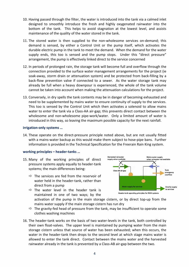
15. Many of the working principles of direct pressure systems apply equally to header‐tank systems; the main differences being:
The services are fed from the reservoir of water held in the header‐tank, rather than direct from a pump
The water level in the header tank is maintained in one of two ways; by the activation of the pump in the main storage cistern, or by direct top‐up from the mains water supply if the main storage cistern has run dry
The gravity‐fed head of pressure from the tank, may be insufficient to operate some clothes washing machines
16. The header‐tank works on the basis of two water‐levels in the tank, both controlled by their own float‐valves. The upper level is maintained by pumping water from the main storage cistern unless that source of water has been exhausted; when this occurs, the water in the header‐tank then drops to the second level at which stage mains water is allowed to enter the tank direct. Contact between the mains water and the harvested rainwater already in the tank is prevented by a Class‐AB air‐gap between the two.

5
system components schematics layouts … 17. Schematic diagrams of Freerain “Header‐tank” and “Direct Pressure” systems are
shown below; these diagrams can also be used to double‐check the type of system you will be installing (ie with or without a header‐tank), and as a visual aid for confirming delivery of goods ordered:
H
Header‐tank Systems
Direct Pressure Systems

6
ancillary items … 18. Both systems are supplied
with a pump and associated fittings (shown opposite); otherwise, the main distinguishing features between the two at the point of delivery are provision of:
Header‐tank & fused‐spur (HT‐version)
A top‐up controls box (DP‐version)
the pump … 19. The standard pumps supplied with Freerain domestic systems are DAB Divertron 1000‐
M submersible pumps, the key features of which are:
Built‐in integrated electronics designed to automatically start and stop the pump Equipped with in‐built dry‐run protection Built‐in non‐return valve Pre‐fitted float valve:
Activates mains top‐up on direct‐pressure systems when needed during long dry spells
On header‐tank systems, provides additional pump protection by cutting‐off the power to the pump before its in‐built protection becomes necessary
Power & Performance: Required – 230V, 50‐Hz Output – 0.55kW, 0.75‐HP
Installation: Chain‐suspended from the neck of the tank Pre‐measured to provide 150‐mm clearance between pump and tank‐base
Dimensions & data; as shown below:

7
filter options …
Compact Filter
The Compact filter is one of the most popular in the Freerain range, being particularly useful when there is a requirement for minimum/zero invert level drop between the inlet and the outlet.
The key technical characteristics of the filter are:
Connection capacity for roof areas up to 150 m²
All connections DN 100 (110mm OD). No height difference between inlet and outlet.
Mesh size of filter cartridge 0.7 x 1.7 mm.
PF Filter
For flow‐rates associated with larger roofs, or where an invert drop across the filter is desirable, we specify use of the PF filter which works on similar principles to the Compact filter.
The key technical characteristics of the PF filter are:
Connection capacity after DIN 1986 for roof areas up to 200 m².
All connections DN 100. Small height difference of 66 mm between rainwater inlet and waste water outlet.
Mesh size of filter cartridge 0.7 x 1.7 mm.

8
VF‐1 Filter
Completing the range of filters most likely to be used on domestic‐scale projects, the VF‐1 filter would be most likely to be specified to complement the larger tanks in the Freerain range.
The key technical characteristics of the VF1‐filter are:
Suitable for connection to roof areas up to 500 m².
Height difference between inlet and outlet 300 mm.
Suitable in‐tank installation as shown below
Or can be provided with its own neck for installation pre storage tank

9
Freerain “G‐tank” sizes & specifications …

10
NB: Top sliding section can be trimmed on site to reduce overall height dimension when necessary

11
Freerain “G‐tanks” standard connection orientations …
Buyer Notes:
1. Service-ducts need to be directly aligned with controls location 2. On direct-pressure systems, service-ducts must drain towards tank 3. Invert-drops across filters are CF-zero; PF-66mm; VF1-300mm
12
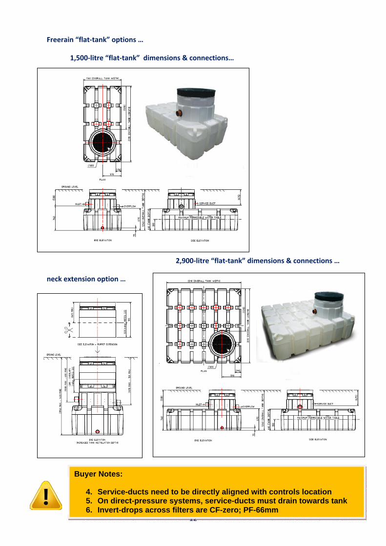
Freerain “flat‐tank” options …
1,500‐litre “flat‐tank” dimensions & connections…
2,900‐litre “flat‐tank” dimensions & connections …
neck extension option …
Buyer Notes:
4. Service-ducts need to be directly aligned with controls location 5. On direct-pressure systems, service-ducts must drain towards tank 6. Invert-drops across filters are CF-zero; PF-66mm

13
installing the tank preliminaries … 20. Responsibility for ordering the right tank for the project, and with the right connections
to suit the drainage and service‐duct connections to suit the underground works, lies with the Buyer.
21. The Site Agent is responsible for checking that the right tank has been delivered to site
with all concerned knowing all the implications of its installation; these include factors such as:
Required capacity and any dimension constraints Site access and routes to site Filter and other fitments requirements Orientation of connections, and any associated invert‐level changes Ground conditions, re: soil type, water table, contamination etc Depth of excavation, adjacent structures, their foundations and proximity to utilities Traffic‐bearing characteristics Topography (adjacent slopes and banks) and proximity to trees Delivery timetables
22. Delivery: Timing of the delivery of the system will always be pre‐agreed with the Site
Agent and is usually timed to ensure that the tank can be down‐loaded, transferred to plot, installed and back‐filled with the minimum of delay.
23. Accountability: Responsibility for the tank passes to the Site Agent once unloading
commences; it is therefore important that the buyer accepts the condition of the tank on arrival before they attempt to move or attach lifting equipment.
tank handling … 24. Freerain tanks are designed to be lifted and manoeuvred only when empty; they are not
therefore to be lifted when containing water under any circumstances as this will add considerable weight.
25. It is recommended that the tanks be unloaded from delivery lorries, moved around site,
and lowered into their installed position by attaching lifting straps/chains and appropriately sized D‐shackles to the lifting points provided, or by use of lifting straps around the whole tank; points to note are:
The centre of gravity of the tank needs to be established by trial & error before fully raising the tank
Chain lengths need to be adjusted so that the tank lifts horizontally
To stabilise the load when moving around site, guide‐ropes should be attached to enable operatives to control load‐swing from a safe distance

14
installation overview … 26. Freerain systems include tanks, designated “G‐tanks” and “Flat‐tanks” per the
specifications above, that have been specifically designed to store harvested rainwater 27. The tanks are designed to be installed in specific accordance with the instructions that
follow; the civils design of a structural engineer is to be followed if any of the following tank installation conditions are present:
Trafficking by vehicles other than ride‐on lawn‐mowers Closer than 4‐metres to the foundations of another structure Closer than 4‐metres to an adjacent significant change in ground‐level Outside the depth parameters identified in the two installation diagrams below
28. Installation in heavy clay soil or in areas that will experience high water‐tables will also
affect the installation as highlighted on the installation diagrams. 29. If site personnel are faced with any of the conditions noted above, they should seek
supervisory advice before commencing tank installation. 30. The tanks are designed to take pedestrian and light mower loading only, with the range
of excavation depths shown in the installation diagrams below; 31. The customer may, if wished, substitute their own brick‐construction manhole and cover
provided these are so constructed that they do not transfer any weight onto the tank. 32. Pipe‐falls must be a minimum of 1:100 in the direction of water‐flow, ie rainwater
delivery pipe and service duct towards the tank, and the overflow away from the tank 33. The installation of the rainwater storage tank, and its connection to the water‐supply,
water‐overflow and service‐duct pipes should be undertaken at the same time as the overall underground works for the project.
34. The tank should be aligned to provide the straightest possible service duct run between
the tank and the Control Unit as other pipe‐work and cabling etc need to be fed through this duct at a later stage; the figure below shows this ideal relationship (bearing mind the possible “G‐tank permutations thumb‐nailed opposite)

15
35. The tank must be handled and installed strictly in accordance with the instructions at paragraph‐26 above; once installed, the position of the tank is to be clearly marked and over‐driving by vehicles within 4‐metres of a tank edge is strictly forbidden.
36. All pipe‐work associated with a rainwater harvesting system must be kept totally clear of
site debris, to which end they must have sealed ends when being pulled through. 37. To prevent roof‐water entering the tank prior to the system entering service, the in‐tank
filter is to be covered with polythene until the property is ready for occupancy; this cover is to be removed as a part of the commissioning process.
precautions … 38. To ensure the integrity of the tank is not prejudiced during installation, and satisfactory
subsequent operation of the complete system, the following precautions are to be strictly observed:
Allow the tank to settle onto the pea‐gravel base under its own weight initially, and the weight of the water introduced into it
Care is to be taken to ensure that site debris/dust is not allowed to enter the tank during or after its installation
Under no circumstances: Tamp‐down the infill with machinery Tamp‐down finished ground level with machinery Drive vehicles over tanks installed as above
step‐by‐step guide … 39. The following is a step‐by‐step guide to the installation of the tank when none of the
abnormal conditions noted at paragraphs 27 & 28 above are present:
Arrangements should be made for the tank to be delivered, coincident with the day it is due to be installed; with this in mind, when delivery is expected ensure:
Suitable access and parking arrangements have been made for the delivery vehicle
Plant is available to unload the tank A clear route has been designated between the delivery vehicle and the installation site
The installation site is level and clear of obstacles and site debris and, ideally: The water ingress pipe‐work is complete and ready for connection The water overflow pipe‐work is complete, ready for connection, and is itself connected to the surface water management system (soak‐away, storm‐drain or attenuation as appropriate)
The service duct is ready for connection, complete with: internal draw‐cord provided; this should be left in‐place on completion
32‐mm High Performance Polyethylene (HPP) delivery pipe, fed through, section by section, as the service duct is installed
16
Before starting the installation, confirm no added precautions (see paragraph‐48 above) apply; ie, the instructions of a structural engineer must be followed, if any of the following apply:
Vehicular over‐trafficking required Closer than 4‐metres to adjacent foundations, earth bank (above or below) or raised patio
Depth of installation, or constraints arising from clay soil or high water‐table not in accordance with installation diagrams below
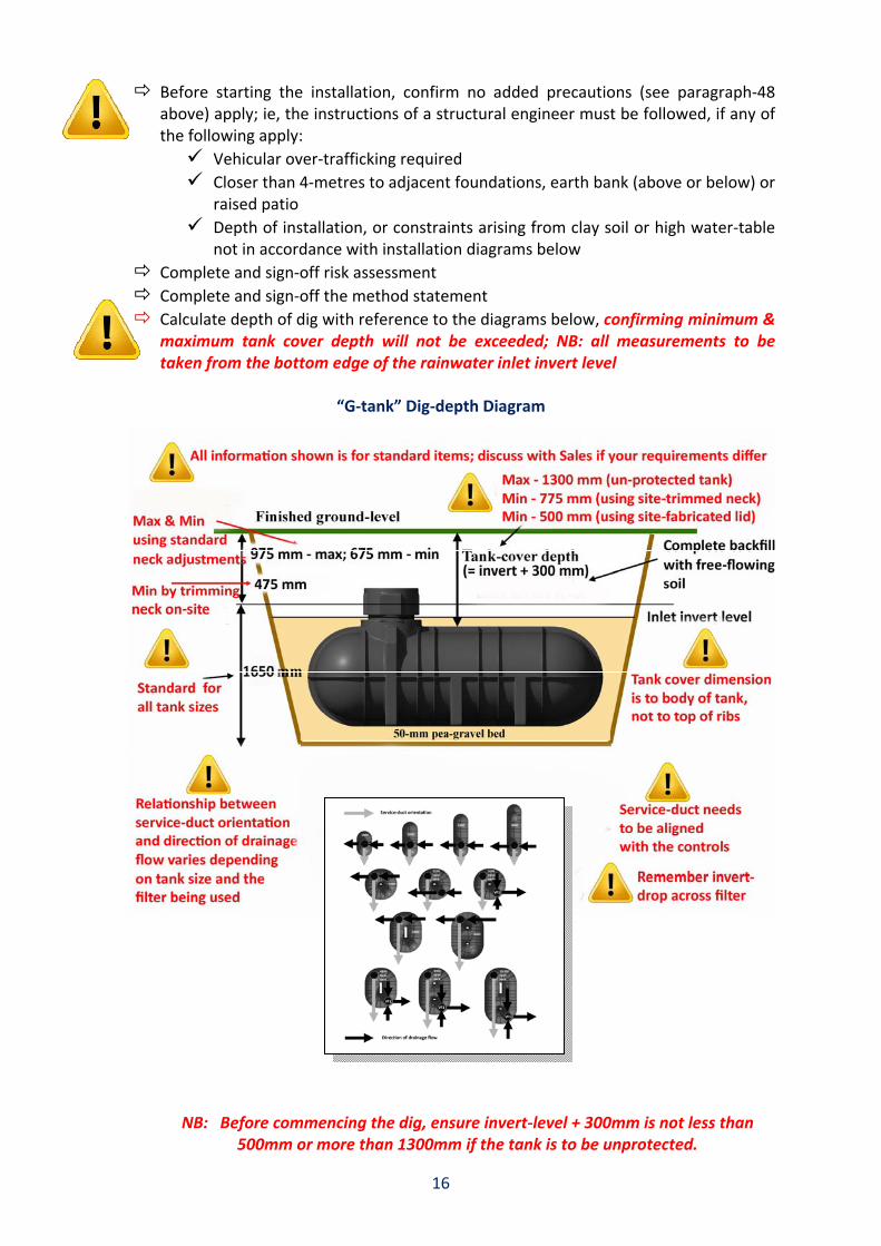
Complete and sign‐off risk assessment Complete and sign‐off the method statement Calculate depth of dig with reference to the diagrams below, confirming minimum & maximum tank cover depth will not be exceeded; NB: all measurements to be taken from the bottom edge of the rainwater inlet invert level
“G‐tank” Dig‐depth Diagram
NB: Before commencing the dig, ensure invert‐level + 300mm is not less than 500mm or more than 1300mm if the tank is to be unprotected.

17
“Flat‐tank” Dig‐depth Diagram
Line‐mark dig area, allowing for: Alignment of tank water entry and exit connections, and the service‐duct connection (NB: The service duct most slope towards the tank on direct pressure systems to gravity‐feed the mains‐water top‐up)
(Tank plan‐view dimensions) + (300‐mm for tank manoeuvre/access) + (suitable allowance for battering depending on ground conditions)

18
Dig the excavation, anticipating that ground water ingress may be experienced in the process; if necessary, keep water interference to a minimum by use of a pump; if the ground needs to be stabilised to provide a firm base for the tank, the excavation depth should be increased by 250‐mm and replace with a mixture of hard‐core and sand
Bed the bottom of the excavation with 50‐mm of 10‐mm washed pea‐gravel (150‐mm for the “Flat‐tank”)
Position tank on the pea‐gravel base, and check vertical and horizontal alignments between tank connectors and the drainage runs/service duct, allowing for 10‐mm of tank settlement at the next step
Fill 1/3rd full of water to settle tank into the pea‐gravel, and bring connectors and pipe‐work into final alignment
Connect all pipe‐work (ie rainwater‐in, overflow‐out, and service duct) Install neck and seal the joints with a good bead of silicon sealant to avoid later ingress of ground‐water; then fit lid to ensure that no backfill material can enter the tank
Backfill around and under the tank body and sides of the excavation with more 10‐mm washed pea‐gravel up to the level of the water inside the tank
Continue backfilling around and under the tank with pea gravel until the crown of the tank is covered with 50‐mm of pea gravel (150‐mm for the “Flat‐tank”)
Continue filling the tank water, keeping pace with the backfill level up to the level of its inlet/outlet connections
Complete backfill to finished ground level with free‐flowing material Once the installation is complete and the tank connected:
Install filter (if not already installed) Seal filter with strong polythene (to prevent roof water entering the tank until the whole system is ready to be handed‐over to the end‐user)
Secure the tank lid Mark out an exclusion zone 4‐metres outside the original excavation footprint to prevent site vehicles accidentally driving over the tank during construction work

19
installing the other components overview … 40. The services to be supplied by the rainwater harvesting system (usually the toilets, the
clothes washing machine and the outside tap) are to be fed by pipe‐work that is independent of the mains water system, with no interconnections between the two except via the air‐gaps provided for top‐up purposes. Also, “Fluidmaster” valves are to be fitted to all cisterns.
41. The pipe‐work conveying rainwater inside a building should ideally be plastic and be
installed and tested for air‐tightness at the 1st‐fix plumbing stage. Outside the building, black High Performance Polyethylene (HPP) pipe‐work marked with a green stripes along its length must be used in accordance with Annex‐C to BS‐8515.
42. The system includes a signage and pipe‐marking pack which must be used appropriately
throughout the system, per the examples below: 43. Other 1st fix tasks include making a 10‐amp fused spur electrical and mains water
supplies available for connection when the remainder of the components are installed. 44. The 2nd fix work brings the system to a position where it is fully operational, and
commissioned, ready to be handed‐over. 45. The integrity of the services supply‐side pipe‐work is to be air‐pressure tested, and all
associated fixtures and fittings properly installed, before power is applied to the system.

20
header‐tank systems … 46. The arrangement/relationship of components in header‐tank systems is shown diagrammatically
below:
Storage tank with pre-
fitted filter & calmed inlet
Pump & dry-run
float-switch
Isolation cock, pressure-gauge &
in-line strainer assembly
Power supply
RWH supply Power
supply to
pump
Both via
service-duct
Header-tank Mains
top-up supply
Supply to header-
tank Supply to services
LED lit when
rainwater being used
NB: 1. Insulation jacket must not obstruct air‐gaps 2. Both warning overflows must be connected to outside waste using 32‐mm push‐fit waste pipe ( ie, not the solvent‐weld variety)
NB:
“Dead‐leg” on mains top‐up supply to be avoided by use of a check‐valve

21
47. A typical installation sequence for header‐tank systems will include:
Preparatory:
Positioning the header‐tank in the loft‐space Positioning stop‐cock, pressure gauge & in‐line strainer cluster in required position (usually adjacent to the power‐supply position)
Providing a 13‐amp power supply connection
Plumbing:
Around the header‐tank: Installing supply pipe‐work to services Providing mains top‐up supply Connect rainwater supply pipe‐work Connect over‐flow warning pipe‐work
Around the stop‐cock cluster: Connect 32‐mm MDPE rainwater supply‐pipe from main storage tank Connect 15mm internal delivery pipe to supply the header‐tank
Around the main underground rainwater storage tank: Connect pump outlet to 32‐mm MDPE rainwater supply‐pipe in the service duct using flexible hose and fittings provided
Suspend the pump in tank using pre‐set chain provided Pull pump power cable through the service duct (leaving cord in place for later use whenever needed)
Electrics: Connect the 13‐amp supply and pump power cable as shown opposite
Plumbing: Switch‐on power, and check:
All joints & pipe‐work sound
Pressure gauge reading 3‐4 bars, and steady
Water provided automatically to services when operated Pump is not running when there is no demand Pump dry‐run float‐switch operates (tested by slowly raising pump in the tank with outside tap running)
Mains top‐up into header‐tank operates (tested by closing supply cock‐stop and operating services until top‐up activates)

22
direct pressure systems … 48. The arrangement/relationship of components in direct pressure systems is shown
diagrammatically below: 49. A typical installation sequence for the direct pressure systems will include:
Preparatory:
Positioning the top‐up control box in a suitable location Positioning stop‐cock, pressure gauge & in‐line strainer cluster in required position (usually adjacent to the top‐up control box position)
Providing a 13‐amp power supply connection to the control box Providing a mains‐water supply connection to the control box
Storage tank with pre-
fitted filter & calmed inlet
Pump & top-up
float-switch
Isolation cock, pressure gauge & in-line strainer assembly + expansion vessel
Supply to services
Controls
Controls, incorporating connection to power supply &
mains top-up supply
RWH supply
Mains top-up supply
Power supply
to pump
Power supply &
top-up cable
All via service-duct

23
Plumbing:
Around top‐up controls box (see diagram opposite):
Make good connection to the mains supply Make good the mains top‐up connection between tun‐dish and the service‐duct, using 32‐mm grey waste pipe terminating 100‐mm inside the duct (NB: Do not establish a pipe‐work connection running all the way from the tun‐dish back to the tank, as this will not work)
Around stop‐cock cluster: Connect 32‐mm MDPE rainwater supply‐pipe from main storage tank
Connect 15mm delivery pipe to supply the services
Around the main underground rainwater storage tank:
Connect pump outlet to 32‐mm MDPE rainwater supply‐pipe in the service duct using flexible hose and fittings provided
Suspend pump in tank using pre‐set chain provided Pull top‐up cable through the service duct Pull pump power cable through the service duct (leaving cord in place for later use whenever needed)
Electrics: Connect the 13‐amp supply, pump power cable and top‐up cable as shown opposite:
Plumbing: Switch‐on power, and check:
All joints & pipe‐work sound
Pressure gauge reading 3‐4 bars, and steady
Water provided automatically to services when operated
Pump is not running when there is no demand
Pump dry‐run operates (tested by slowly raising pump in the tank with outside tap running)
Mains top‐up operates (tested by slowly raising the dry‐run float‐switch in the main storage tank until top‐up activates)
24
commissioning 50. Commissioning is the final stage before the system is handed‐over to the end‐user and is
shown to be functioning correctly; commissioning is intended to ensure:
The installation is complete and “Fluidmaster” valves fitted to cisterns All connections to the mains water top‐up unit are correct The pump and associated fittings and cables are correctly positioned in the tank Pump dry‐run protection working (checked as explained above) The filter is correctly housed The mains back‐up is functioning (checked as explained above) The system is holding pressure There are no leaks or weeps The installation and user manuals are present for the end‐user On completion of the commissioning checks, the in‐tank filter is to be lined with polythene to prevent rainwater entering the tank before the property is sold and occupied
51. Bearing in mind that by this stage much of the installation work may no longer be visible,
there is the potential for tradesmen to satisfactorily test the system at the completion of their work, but for it to subsequently malfunction due to hidden defects arising during installation.
52. Typical examples of poor workmanship that are likely to cause subsequent operational
problems, include:
Failure to fit leaf‐guards to down‐pipes, leading to a blockage of the pre‐tank filter Underground pipes being poorly joined, leading to the ingress of ground‐water Tank neck & lid assemblies being poorly sealed, again leading to the ingress of ground‐water
Site dust/soil and debris being allowed to enter into the storage tank or drainage runs leading to poor water quality and premature pump failures
Failure to keep delivery pipes sealed during pull‐through, leading to site debris gaining entry to the pipe
Surface water being allowed to enter the tank for a prolonged period (ie in excess of 20‐days) and stagnating before the system enters regular service
53. This places a premium on good workmanship and supervision during the installation
process to ensure:
No debris is allowed to enter the tank or any of the pipe‐work The tank and pipe‐work are undamaged, and all connections are water‐tight Invert levels are correct, and backflow prevention valves are fitted in high water‐table installations, or if the overflow is connected to a storm‐drain
A filter cover is fitted until immediately before the system is handed‐over to the end‐user

25
using the system handing‐over … 54. The system is now ready to be signed‐off by the commissioning tradesman, and handed‐
over to the client, covering all relevant points such as:
Demonstrating use of the equipment, and its controls Explaining any system limitations/constraints Identifying the major components, their inter‐relationship and normal function Explaining maintenance requirements Running through the fault‐finding guide Providing system support contact information The need to remove the filter seal when the property is about to be occupied Providing the Safety File copies of the O&M Manual (commercial systems) or Installation & User Manuals (domestic systems)
Arrangements also need to be in place to ensure that the end‐user receives an equally
comprehensive hand‐over. … safety & access … 55. Proper risk assessments are to be made whenever maintenance work is undertaken on
the system. 56. For most of the checks to be made during routine maintenance and repair activities,
electrical power will need to be “on”, and all system stop‐cocks “open”; however, care must be taken to:
Isolate electrical power when appropriate to the work being undertaken
Close stop‐cock and isolate the pump when plumbing connections need to be broken (during removal and cleaning of in‐line strainer, for example); re‐made connections are to be properly re‐taped with PTFE, where appropriate
… routine maintenance … 57. The routine maintenance requirements of the system is limited to a quarterly check of:
Whether the user has experienced any problems or unusual symptoms
The correct operation of services, including dry‐run protection & mains top‐up
No signs of leaks or weeps
No sign of wiring deterioration

26
Correct operating pressure
Gutters clean, leaf filters in place, and pre‐tank and in‐line filters removed/cleaned
Good water quality in the main storage tank, and to services
No “tide‐mark” in the neck of the tank to indicate over‐filling (ie overflow failure)
Tank contents matches contents gauge (if present) and the weather/usage pattern
… fault finding … 58. If problems are being experienced, Freerain provide a help‐line service during business
hours on 0845‐127‐0001. 59. Generic reasons why systems may malfunction include:
No power supply to the system; check fuses etc
No water in the tank; check pre‐tank filter is clean and operation of the back‐up
Pump inoperative; may need replacing or re‐setting (power “off”/”on”)
Incorrect top‐up operation; check float‐valve/sensor suspension and operate manually
Component failures
Pump “hunting” (when services not being used); weep or leak on the delivery side of the system (will shorten pump life and may cause it to fault‐out)
Continuous pumping (but no pressure to services); delivery pipe split or disconnected from the pump (system needs to be switched‐of as soon as detected to protect the pump and avoid energy waste)
60. NB: It should be noted on header‐tank systems that a system failure may not be
immediately apparent to the end‐user, as water will still continue to be available to services via the mains top‐up feature. This is easily detected by:
Noting when the LED on the fused power switch is “off”; this indicates that the header‐tank is using mains‐top‐up water
Confirming that this occurs only when to be expected with the prevailing weather conditions (ie lack of recent rainfall)

27
… water quality … 61. The water appearing in toilet bowls should look clean/clear; as noted above, checking
the quality of the water in the main storage tank is one of the requirements of periodic maintenance because:
Poor quality water in the tank will provide poor quality water to the services which is unacceptable
It may be an indicator of pre‐tank filtration issues, which may additionally affect its efficiency at harvesting water
Poor quality water may damage the pump, or reduce pump life
62. In the event of water‐quality issues arising, potential causes include:
System continuing to harvest rainwater which remains unused during the period between installation and occupancy (avoided by sealing the filter until the system is ready for use)
Foreign matter being allowed to enter the tank during the construction process (which must be avoided)
Ground‐water ingress (avoided by sealing properly the neck shaft and all underground connections during installation)
Back‐flow from under‐performing soak‐aways (avoided by installation of one‐way valves on the over‐flow)

28
FREERAIN LTD TERMS & CONDITIONS OF BUSINESS (These do not affect the customer’s statutory rights)
Please note that all goods are provided on a supplied-only basis, to be installed as a working system by the customer or their
agents; any faults arising from mis-installation or mis-handling are the responsibility of the installer. Our supplies are not
subject to the CIS rules and no CIS deductions are therefore to be made to invoices
General Terms NB: Breach of these conditions will invalidate the Warranty
The following applies only to the supply of goods (namely full or part rainwater harvesting systems); where a separate contract for the supply of services is required, such as for installation support and site visits etc, separate terms, conditions and charges will apply to that contract.
All goods provided under these terms & conditions are to be used in accordance with the associated Installation Manual, Users Manual, or other written instructions provided by the Company.
As an un-contracted service, the Company provides installers and users of the goods it supplies with a free telephone advice line; all telephone advice is provided in good faith but, if different/additional to written information contained in the Installation and Users Manuals, is only to be acted directly upon when followed-up by a written confirmation.
Quotations & Prices
Only our written quotations are to be used as a basis for ordering. The prices contained in our quotations are fixed for a period of 3-months from the date of issue, unless stated otherwise.
All quoted prices are exclusive of VAT, unless stated otherwise.
Orders
Orders are only accepted once we have issued confirmation of acceptance, and on the basis that all terms and conditions here set-out have been understood and accepted by the buyer.
Ordering
Written confirmations (letters, fax or e-mail) are required for all orders.
Technical Specification Changes
All specification changes are to be agreed in writing by both parties ahead of shipping.
Amendments
Any amendments to original quotation/order details are to be confirmed in writing by both parties.
Delivery Times & Arrangements
The delivery times relevant to your order will be as set out in our written quotation; we will use our best endeavours to meet precise delivery arrangements within the constraints of the stated delivery time, provided at least 5-working days notice is given.
Should, for reasons beyond Freerain Ltd control, delivery of goods does not take place as mutually arranged, Freerain Ltd will not be liable for any additional costs incurred by the client.
Cancellation of Orders
Orders may not be cancelled once it has been delivered fully or in part
In the event that an order (in full or in part) is cancelled after it has been placed but pre-delivery, the following cancellation charges will apply:
7.5% of the value of the order once it has been accepted by Freerain and confirmation sent to the buyer
15% of the value of the order where working drawings & installation manuals have been produced and sent
30% of the value of the order where signed drawings have been returned by the customer, and production has commenced
60% of the value of the order where the goods have been manufactured and are in-stock awaiting delivery instructions
Undeliverable goods
In the event goods are not able to be off loaded when delivered in accordance with the agreed arrangements, due to the client not being in a position to receive them, the client will be responsible for any storage, additional shipping/re-shipping costs, which arise.
Damages in Transit
All goods are to be unpacked on receipt and checked for damage in transit; any claims for replacement items are to be made within 48-hours of delivery. The customer copy of the Packing List needs to be signed and returned at this stage to validate the Warranty.
Responsibility for off-loading goods lies with the client and must be undertaken in accordance with the instructions provided; any damage arising during or subsequent to off-loading shall be the client’s responsibility.
Returned goods
Shipping costs associated with the returning of goods is the responsibility of the customer, unless agreed otherwise. Should any parts become lost or damaged, it is the responsibility of the customer to use the appropriate service with insurance/protection.
Payment Terms
For orders less than £5,000 nett, pre-payment is required, unless agreed otherwise in writing beforehand and all invoices are to be settled in full ahead of shipping.
For orders greater than £5,000 nett or otherwise agreed credit account facilities are available, subject to prior checking by the credit control department.
Warranty
The warranty period starts on the date the goods are delivered to site. The Warranty is validated by completion and return of the second copy of the Packing List enclosed with the system or component(s) on delivery. The terms of the Warranty are:
i) All components are covered by a parts only guarantee from the time of delivery.
ii) Replacement parts will be provided in the event of failures in service, for the period as outlined below after the date of delivery. Replacement parts shall only be issued on return of the defective parts, unless agreed in writing.
Full domestic systems – 24 months (see note v) External only (Gardening) systems – 12 months Commercial systems – 12 months All other system and parts - 12 months, unless stated at the time.
iii) Failures resulting from improper installation, misuse and/or with signs of physical mistreatment are not covered by the Warranty.
iv) Domestic systems are optimised to provide harvested rainwater to supply WC’s throughout the house, outside tap functions and a washing machine situated on the ground floor. Other configurations/usages should perform equally well, but are not guaranteed.
v) Tanks made from polyethylene carry a 15-year warranty against failure caused by a manufacturing defect. To validate this warranty, the tanks must be used and installed fully in accordance with Freerain instructions which includes taking advice from a professional appointed structural engineer under the circumstances identified in the instructions. Claims made against this warranty are to be accompanied by a report supplied by a mutually agreed independent expert, whose fees will be paid by Freerain in the event that a manufacturing defect is shown to be the cause of any failure.
vi) Drinking water systems are subject to the separate mutually agreed “risk assessment” that form the contract under which these are supplied.
System Breakdowns
System breakdowns that cannot be rectified by the end-user with reference to the user guide and with telephone technical support from Freerain, will need to be attended to by the customer’s agent (usually the original installer or appointed plumber). Freerain will assist the agent/plumber (via the telephone) to rectify the problem. Any defective parts will then be issued with reference to the terms of the warranty.
Commissioning
A commissioning request form must be completed and signed prior to any visit. System commissioning does not include labour or installation work. Prior to our representative(s) arriving on site the system must be fully installed as per the written instructions provided. Should the system not be in a state of readiness for commissioning and/or where remedial works be required as a result of the initial report, additional charges may apply. Specific terms relating to a commissioning visit can be found on the commissioning request form and the commissioning report form.
Title
All goods shall remain the property of Freerain Ltd so long as any money is outstanding in relation to these or any other goods previously supplied.
Freerain Ltd reserve the right to recover any goods that have not been paid for in accordance with the account facilities provided, and the purchaser agrees to make such goods available for this purpose, and provide any access needed to effect recovery.
In the event a purchaser’s standard documentation includes wording that may, or appear to, invalidate the above retention of title conditions, such contra-terms are rejected unless specifically agreed in writing.
Freerain Limited, Sylvan Way, Off Great North Road, Newark, Nottinghamshire NG24 3UT Sales: 0845 1250 000 Tech: 0845 1270 001 Fax: 01636 894909 email: [email protected] web: www.freerain.co.uk
registered no. 3521704 VAT no. 706 4275 43 Registered Office: Millennium Green Business Centre, Rio Drive, Collingham, Newark, Notts NG23 7NB


