52
INSTALLATION MANUAL AC12/AC42 Autopilot Computer 20222568 / A Sw.1.1 English BAR CODE A C
INSTALLATION MANUAL
AC12/AC42 Autopilot Computer
20222568 / A Sw.1.1 English
BAR C
OD
E
AC
2 | AC12/AC42 Installation manual
Copyright All rights reserved. No part of this document may be reproduced or otherwise copied without prior written permission of Navico Holding AS.
© 2007 by Navico Holding AS
About this manual
Rev. A 19.10.07 First issue
This manual is intended as a reference guide for installing and maintaining the Simrad AC12 and AC42 autopilot computers and other components in an autopilot system.
Please take time to read this manual to get a thorough understanding of the system components and their relationship to a complete autopilot system.
Important text that requires special attention from the reader is emphasized as follows:
Used to draw the reader’s attention to a comment or some important information.
Used when it is necessary to warn personnel that a risk of damage to the equipment or hazard exists if care is not exercised.
AC12/AC42 Installation manual | 3
Content
1 System description ..................................... 5 1.1 General ..................................................5 1.2 How to use this manual.............................5 1.3 Software record .......................................6
2 Installation ................................................. 7 2.1 Installation checklist .................................7 2.2 Unpacking and handling ............................7 2.3 Determine system configuration .................8 2.4 Autopilot system layout.............................9 2.5 Autopilot computer installation................. 11 2.6 Rudder Feedback installation ................... 14 2.7 LF3000 Linear Feedback.......................... 16 2.8 Drive unit installation.............................. 18 2.9 AP24 and AP28 Control unit installation ..... 20 2.10 FC40 and RC42 Compass installation....... 23 2.11 R3000X Remote Control installation ........ 24 2.12 JS10 Joystick ....................................... 24 2.13 S35 NFU Lever installation ..................... 25 2.14 Interfacing .......................................... 25 2.15 SimNet ............................................... 26 2.16 External Alarm..................................... 30
3 Spare Parts List ........................................ 31
4 | AC12/AC42 Installation manual
4 Technical specifications ............................ 35 4.1 AP24 Autopilot System............................ 35 4.2 AP24 Control Unit................................... 36 4.3 AP28 Control Unit................................... 38 4.4 Autopilot Computers............................... 39 4.5 FC40 Fluxgate Compass .......................... 41 4.6 RC42 Rate Compass ............................... 42 4.7 RF300 Rudder Feedback.......................... 43 4.8 RF25 Rudder Feedback ........................... 45 4.9 R3000X Remote Control .......................... 45 4.10 JS10 Joystick ....................................... 46 4.11 SimNet ............................................... 47 4.12 IP protection........................................ 47 4.13 AT10 SimNet/NMEA0183 converter ......... 48
5 Index........................................................ 51

System description | 5
1 System description
1.1 General The autopilot computer is the main unit in the AP24 and AP28 autopilot systems. It contains the steering computer and electronics for the drive unit motor and clutch and provides interface to other system components. Two models, AC12 (8/16 A motor current) and AC42 (30/50 A motor current) are available.
It communicates on the proprietary SimNet data and control network to establish a reliable digital communication and power distribution between the units in the autopilot system as well as other Simrad products.
SimNet provides high speed data transfer and control of Simrad products integrated in a total steering and navigation system.
1.2 How to use this manual This manual is intended as a reference guide for installing and maintaining the Simrad AC12 and AC42 autopilot computers and other components in an autopilot system.
Please take time to read this manual to get a thorough understanding of the system components and their relationship to a complete autopilot system.
Other documentation material that is provided with your system includes an operator manual which includes the setup instructions for the system, a control unit installation guide and a warranty card. The warranty card must be filled out by the authorized dealer that performed the installation.

6 | System description
1.3 Software record When the system is switched on, a status display shows the software versions for the control unit and the autopilot computer. Refer to the autopilot operator manual. Software version Description
SW 1.1.00 First issue
Installation | 7
2 Installation An autopilot system includes several units that need to be mounted in different locations on the boat, and also need to interface with at least three different systems on the boat:
• The boat's steering system
• The boats electrical system (input power)
• Other equipment on board (SimNet interfacing)
In addition, the advanced capabilities of the system require the installer to perform a series of settings and tests to verify proper operation of the system, refer to the check list below.
2.1 Installation checklist 1. Determine the system configuration you are
installing (Page 8)
2. Perform the hardware installation (Page 11)
3. Connect SimNet devices to SimNet (page 26)
4. Perform Set-up (refer to Operator manual)
5. Test Autopilot Operation at Sea (refer to Sea Trial instructions in the Operator manual)
2.2 Unpacking and handling Care should be taken when unpacking and handling the equipment. A visual inspection should be made to see that the equipment has not been damaged during shipment and that all components and parts are present according to the packing list.
An autopilot system will include:
• Control unit (AP24 or AP28) with accessories
− Installation accessories
− Operator manual
8 | Installation
• Autopilot computer (AC12 or AC42) with accessories
− SimNet cable 5,5 m (18’)
− Installation accessories
− AC12/AC42 Installation Manual
• Compass (FC40 or RC42) with 5,5 m (18') SimNet cable attached
• Feedback unit (RF300 or RF25) with transmission rod and cable attached.
• Appropriate drive unit for the installation (unless the autopilot is going to operate an existing drive unit or solenoids).
• Optional equipment that may have been ordered for the installation.
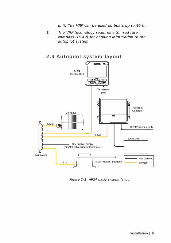
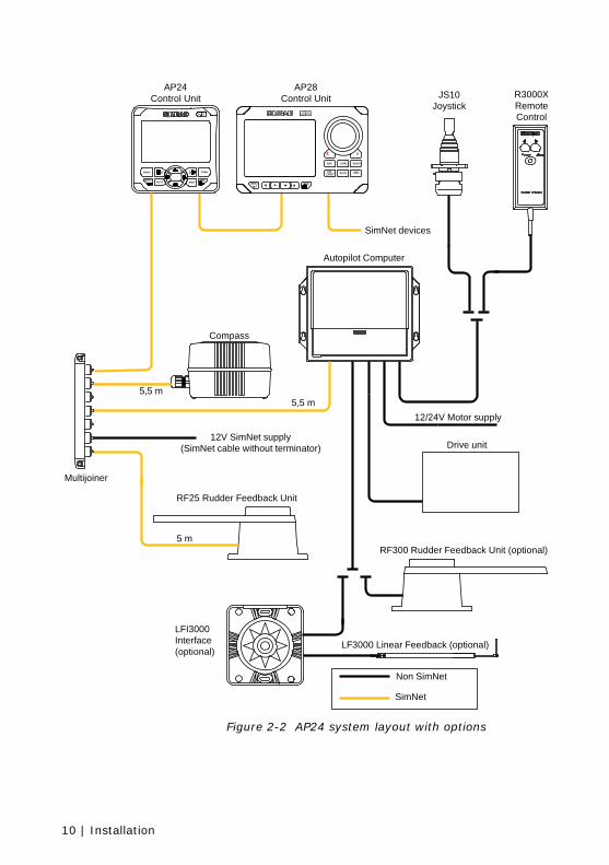
2.3 Determine system configuration It is important to become familiar with the configuration of the system prior to beginning the installation. An autopilot basic single station system is shown in Figure 2-1 and a system layout with options is shown in Figure 2-2
Plan your cabling and configure the SimNet network in accordance with chapter 2.15 on page 26. Pay particular attention to the autopilot computer/drive unit combinations.
As most of the units are communicating on a common network (SimNet) with identical connectors, the installation is simple. Try to mount the units within the standard cable length supplied with each unit. SimNet cables are available from your distributor (see page 33) for connection to other SimNet devices and cable extension.
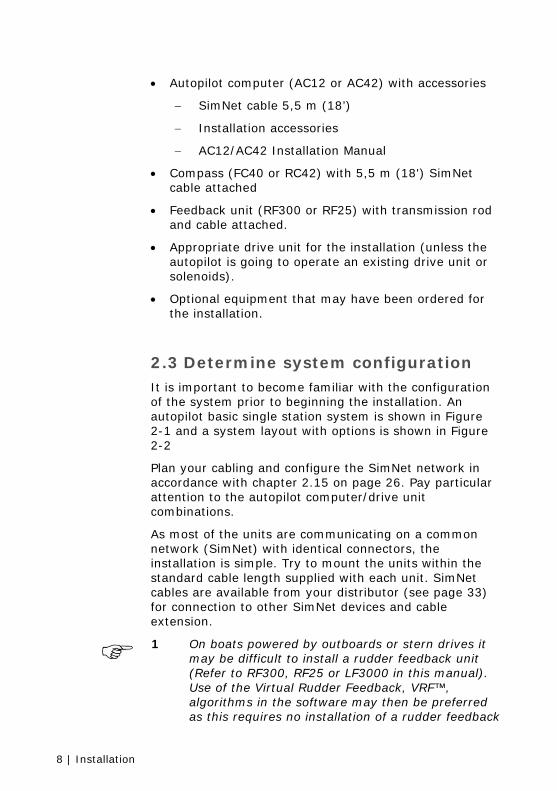
1 On boats powered by outboards or stern drives it
may be difficult to install a rudder feedback unit (Refer to RF300, RF25 or LF3000 in this manual). Use of the Virtual Rudder Feedback, VRF™, algorithms in the software may then be preferred as this requires no installation of a rudder feedback
Installation | 9
unit. The VRF can be used on boats up to 40 ft.
2 The VRF technology requires a Simrad rate compass (RC42) for heading information to the autopilot system.
2.4 Autopilot system layout
12/24V Motor supply
Drive unit
AP24Control Unit
Multijoiner
Compass
5,5 m
5,5 m
5 m
24AP
MODE
MENUAUTO STBY
TURN1010
PWR11
RF25 Rudder Feedback
12V SimNet supply(SimNet cable without terminator)
AutopilotComputer
Non SimNet
SimNet
Terminationplug
Figure 2-1 AP24 basic system layout
10 | Installation
Drive unit
Non SimNet
SimNet
AP24Control Unit
AP28Control Unit JS10
JoystickR3000XRemoteControl
RF300 Rudder Feedback Unit (optional)
LF3000 Linear Feedback (optional)
LFI3000Interface(optional)
RF25 Rudder Feedback Unit
12/24V Motor supply
24AP
MODE
MENUAUTO STBY
TURN1010
PWR11
Autopilot Computer
Multijoiner
SimNet devices
Compass
5,5 m5,5 m
5 m
12V SimNet supply(SimNet cable without terminator)
PWR
NAV WINDTURN
STBYDRIFTNO- AUTO
MENU
Figure 2-2 AP24 system layout with options
Installation | 11
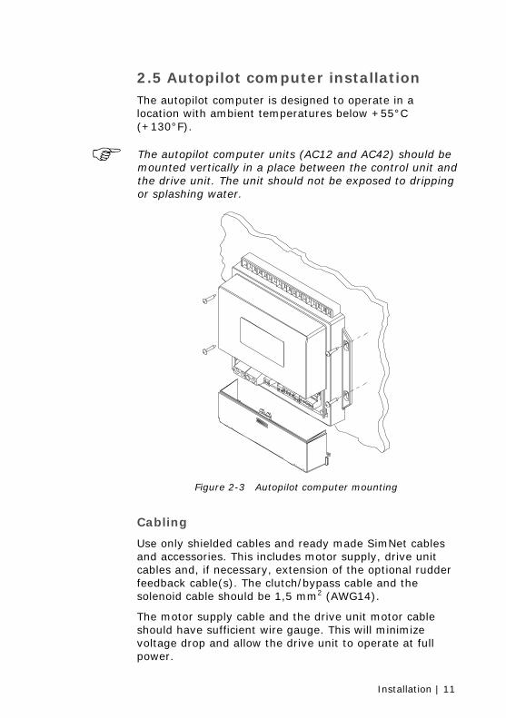
2.5 Autopilot computer installation The autopilot computer is designed to operate in a location with ambient temperatures below +55°C (+130°F).
The autopilot computer units (AC12 and AC42) should be mounted vertically in a place between the control unit and the drive unit. The unit should not be exposed to dripping or splashing water.
Figure 2-3 Autopilot computer mounting
Cabling
Use only shielded cables and ready made SimNet cables and accessories. This includes motor supply, drive unit cables and, if necessary, extension of the optional rudder feedback cable(s). The clutch/bypass cable and the solenoid cable should be 1,5 mm2 (AWG14).
The motor supply cable and the drive unit motor cable should have sufficient wire gauge. This will minimize voltage drop and allow the drive unit to operate at full power.
12 | Installation
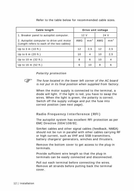
Refer to the table below for recommended cable sizes.
Cable length Drive unit voltage
1. Breaker panel to autopilot computer. 12 V 24 V
2. Autopilot computer to drive unit motor (Length refers to each of the two cables)
AWG mm2 AWG mm2
Up to 3 m (10 ft.) 12 2,5 12 2,5
Up to 6 m (20 ft.) 10 4 10 2,5
Up to 10 m (32 ft.) 8 6 10 4
Up to 16 m (52 ft.) 6 10 8 6
Polarity protection
The fuse located in the lower left corner of the AC board is not put in its final position when supplied from factory.
When the motor supply is connected to the terminal, a diode will light. If the light is red, you have to swap the wires. When the light is green, the polarity is correct. Switch off the supply voltage and put the fuse into correct position (see next page).
Radio Frequency Interference (RFI)
The autopilot system has excellent RFI protection as per EMC Directive 2004/108/EC.
SimNet cables and other signal cables (feedback, NMEA) should not be run in parallel with other cables carrying RF or high current, such as VHF and SSB transmitters, battery chargers/ generators, winches and thrusters.
Remove the bottom cover to get access to the plug-in terminals.
Provide sufficient wire length so that the plug-in terminals can be easily connected and disconnected.
Pull out each terminal before connecting the wires. Remove all strands before putting back the terminal cover.
Installation | 13
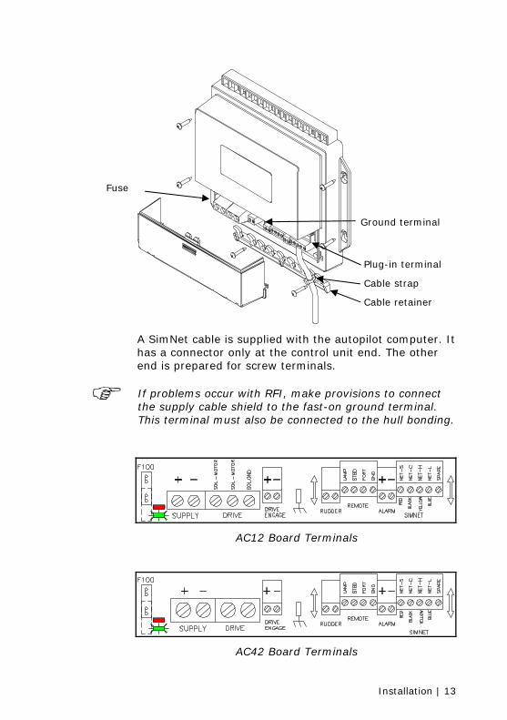
A SimNet cable is supplied with the autopilot computer. It has a connector only at the control unit end. The other end is prepared for screw terminals.
If problems occur with RFI, make provisions to connect the supply cable shield to the fast-on ground terminal. This terminal must also be connected to the hull bonding.
AC12 Board Terminals
AC42 Board Terminals
Plug-in terminal
Cable strap
Cable retainer
Ground terminal
Fuse
14 | Installation
SIMNET
NE
T-S
NE
T-C
NE
T-H
NE
T-L
SPA
RE
Autopilot ComputerAP24 Control Unit
SimNet
RE
D
BLA
CK
YE
LLO
W
BLU
E
J1 J2
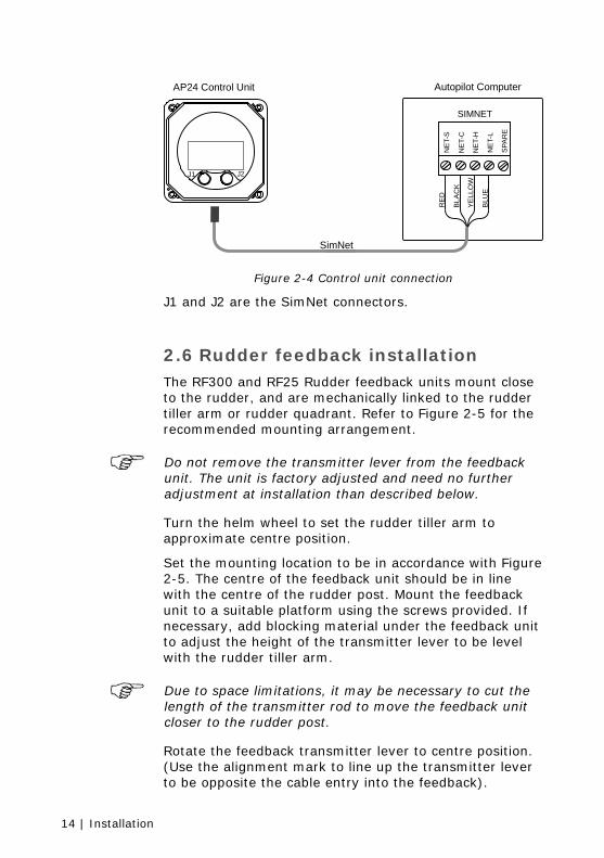
Figure 2-4 Control unit connection
J1 and J2 are the SimNet connectors.
2.6 Rudder feedback installation The RF300 and RF25 Rudder feedback units mount close to the rudder, and are mechanically linked to the rudder tiller arm or rudder quadrant. Refer to Figure 2-5 for the recommended mounting arrangement.
Do not remove the transmitter lever from the feedback unit. The unit is factory adjusted and need no further adjustment at installation than described below.
Turn the helm wheel to set the rudder tiller arm to approximate centre position.
Set the mounting location to be in accordance with Figure 2-5. The centre of the feedback unit should be in line with the centre of the rudder post. Mount the feedback unit to a suitable platform using the screws provided. If necessary, add blocking material under the feedback unit to adjust the height of the transmitter lever to be level with the rudder tiller arm.
Due to space limitations, it may be necessary to cut the length of the transmitter rod to move the feedback unit closer to the rudder post.
Rotate the feedback transmitter lever to centre position. (Use the alignment mark to line up the transmitter lever to be opposite the cable entry into the feedback).
Installation | 15
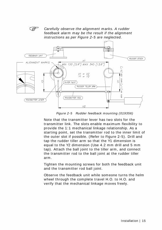
Carefully observe the alignment marks. A rudder feedback alarm may be the result if the alignment instructions as per Figure 2-5 are neglected.
Figure 2-5 Rudder feedback mounting (019356)
Note that the transmitter lever has two slots for the transmitter link. The slots enable maximum flexibility to provide the 1:1 mechanical linkage relationship. As a starting point, set the transmitter rod to the inner limit of the outer slot if possible. (Refer to Figure 2-5). Drill and tap the rudder tiller arm so that the Y1 dimension is equal to the Y2 dimension (Use 4.2 mm drill and 5 mm tap). Attach the ball joint to the tiller arm, and connect the transmitter rod to the ball joint at the rudder tiller arm.
Tighten the mounting screws for both the feedback unit and the transmitter rod ball joint.
Observe the feedback unit while someone turns the helm wheel through the complete travel H.O. to H.O. and verify that the mechanical linkage moves freely.
16 | Installation
Autopilot Computer
* Non polarized(color independent)
Optional RF300 Rudder Feedback
*
RUDDER
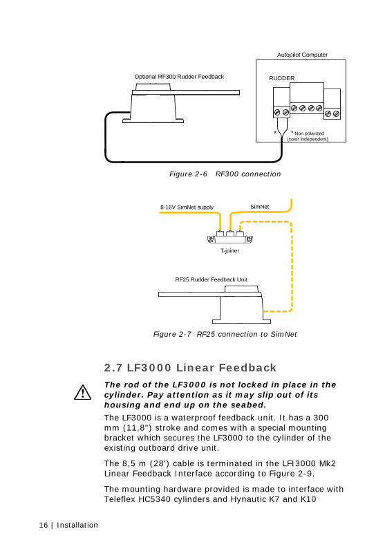
Figure 2-6 RF300 connection
RF25 Rudder Feedback Unit
8-16V SimNet supply SimNet
T-joiner
Figure 2-7 RF25 connection to SimNet
2.7 LF3000 Linear Feedback
The rod of the LF3000 is not locked in place in the cylinder. Pay attention as it may slip out of its housing and end up on the seabed.
The LF3000 is a waterproof feedback unit. It has a 300 mm (11,8") stroke and comes with a special mounting bracket which secures the LF3000 to the cylinder of the existing outboard drive unit.
The 8,5 m (28') cable is terminated in the LFI3000 Mk2 Linear Feedback Interface according to Figure 2-9.
The mounting hardware provided is made to interface with Teleflex HC5340 cylinders and Hynautic K7 and K10
Installation | 17
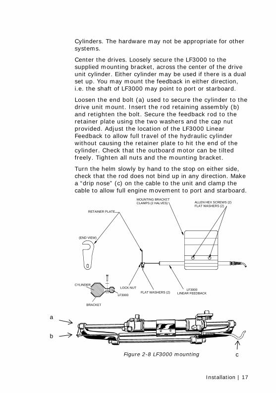
Cylinders. The hardware may not be appropriate for other systems.
Center the drives. Loosely secure the LF3000 to the supplied mounting bracket, across the center of the drive unit cylinder. Either cylinder may be used if there is a dual set up. You may mount the feedback in either direction, i.e. the shaft of LF3000 may point to port or starboard.
Loosen the end bolt (a) used to secure the cylinder to the drive unit mount. Insert the rod retaining assembly (b) and retighten the bolt. Secure the feedback rod to the retainer plate using the two washers and the cap nut provided. Adjust the location of the LF3000 Linear Feedback to allow full travel of the hydraulic cylinder without causing the retainer plate to hit the end of the cylinder. Check that the outboard motor can be tilted freely. Tighten all nuts and the mounting bracket.
Turn the helm slowly by hand to the stop on either side, check that the rod does not bind up in any direction. Make a “drip nose” (c) on the cable to the unit and clamp the cable to allow full engine movement to port and starboard.
LF3000
BRACKET
CYLINDER
(END VIEW)
RETAINER PLATE
LOCK NUTFLAT WASHERS (2)
LF3000LINEAR FEEDBACK
ALLEN HEX SCREWS (2)FLAT WASHERS (2)
MOUNTING BRACKETCLAMPS (2 HALVES)
Figure 2-8 LF3000 mounting
a
b
c
18 | Installation
Autopilot Computer
RUDDER
* Non polarized(color independent)
LFI3000 Mk2Interface
LF3000Linear
Feedback
*
TB2TB1
WH
ITE
BR
OW
N
YE
LLO
W
GR
EE
N
BR
OW
N
WH
ITE
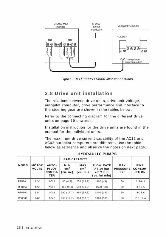
Figure 2-9 LF3000/LFI3000 Mk2 connections
2.8 Drive unit installation The relations between drive units, drive unit voltage, autopilot computer, drive performance and interface to the steering gear are shown in the tables below.
Refer to the connecting diagram for the different drive units on page 19 onwards.
Installation instruction for the drive units are found in the manual for the individual units.
The maximum drive current capability of the AC12 and AC42 autopilot computers are different. Use the table below as reference and observe the notes on next page.
HYDRAULIC PUMPS RAM CAPACITY
MODEL MOTOR VOLTS
AUTO-PILOT
COMPU-TER
MIN cm3
(cu. in.)
MAX cm3
(cu. in.)
FLOW RATE AT 10 bar cm3/min
(cu. in/min)
MAX PRESSURE
bar
PWR. CONSUM-
PTION
RPU80 12V AC12 80 (4,9) 250 (15,2) 800 (49) 50 2,5-6 A
RPU160 12V AC42 160 (9,8) 550 (33,5) 1600 (98) 60 3-10 A
RPU300 12V AC42 290 (17,7) 960 (58,5) 3000 (183) 60 5-25 A
RPU300 24V AC42 290 (17,7) 960 (58,5) 3000 (183) 60 2,5-12 A
Installation | 19
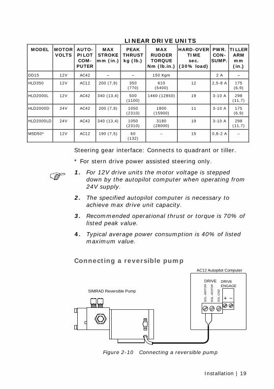
LINEAR DRIVE UNITS MODEL MOTOR
VOLTS AUTO-PILOT COM-
PUTER
MAX STROKE mm (in.)
PEAK THRUST kg (lb.)
MAX RUDDER TORQUE
Nm (lb.in.)
HARD-OVER TIME sec.
(30% load)
PWR. CON-
SUMP.
TILLER ARM mm (in.)
DD15 12V AC42 – – 150 Kgm 2 A –
HLD350 12V AC12 200 (7,9) 350 (770)
610 (5400)
12 2,5-8 A 175 (6,9)
HLD2000L 12V AC42 340 (13,4) 500 (1100)
1460 (12850) 19 3-10 A 298 (11,7)
HLD2000D 24V AC42 200 (7,9) 1050 (2310)
1800 (15900)
11 3-10 A 175 (6,9)
HLD2000LD 24V AC42 340 (13,4) 1050 (2310)
3180 (28000)
19 3-10 A 298 (11,7)
MSD50* 12V AC12 190 (7,5) 60 (132)
– 15 0,8-2 A –
Steering gear interface: Connects to quadrant or tiller.
* For stern drive power assisted steering only.
1. For 12V drive units the motor voltage is stepped
down by the autopilot computer when operating from 24V supply.
2. The specified autopilot computer is necessary to achieve max drive unit capacity.
3. Recommended operational thrust or torque is 70% of listed peak value.
4. Typical average power consumption is 40% of listed maximum value.
Connecting a reversible pump
+
DRIVE DRIVEENGAGE
SO
L.-M
OTO
R
SO
L.-M
OTO
R
SO
L.G
ND
AC12 Autopilot Computer
SIMRAD Reversible Pump
Figure 2-10 Connecting a reversible pump
20 | Installation
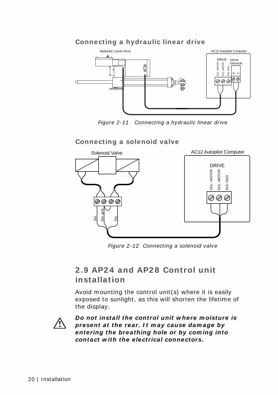
Connecting a hydraulic linear drive
+
DRIVE DRIVEENGAGE
SO
L.-M
OTO
R
SO
L.-M
OTO
R
SO
L.G
ND
AC12 Autopilot ComputerHydraulic Linear Drive
Figure 2-11 Connecting a hydraulic linear drive
Connecting a solenoid valve
Sol
.
Sol
. gnd
.
Sol
.
DRIVE
SO
L.-M
OTO
R
SO
L.-M
OTO
R
SO
L.G
ND
AC12 Autopilot ComputerSolenoid Valve
Figure 2-12 Connecting a solenoid valve
2.9 AP24 and AP28 Control unit installation Avoid mounting the control unit(s) where it is easily exposed to sunlight, as this will shorten the lifetime of the display.
Do not install the control unit where moisture is present at the rear. It may cause damage by entering the breathing hole or by coming into contact with the electrical connectors.
Installation | 21
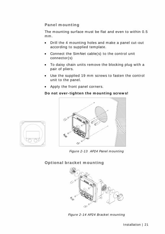
Panel mounting
The mounting surface must be flat and even to within 0.5 mm.
• Drill the 4 mounting holes and make a panel cut-out according to supplied template.
• Connect the SimNet cable(s) to the control unit connector(s)
• To daisy chain units remove the blocking plug with a pair of pliers.
• Use the supplied 19 mm screws to fasten the control unit to the panel.
• Apply the front panel corners.
Do not over-tighten the mounting screws!
Figure 2-13 AP24 Panel mounting
Optional bracket mounting
Figure 2-14 AP24 Bracket mounting
22 | Installation
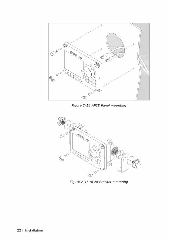
Figure 2-15 AP28 Panel mounting
Figure 2-16 AP28 Bracket mounting

Installation | 23
2.10 FC40 and RC42 Compass installation
Figure 2-17 Mounting
The heading sensor is the most important part of the autopilot system and great care should be taken when deciding the mounting location. As the heading is displayed on the control unit, the heading sensor can be mounted at a remote location.
The compass can be mounted on deck or bulkhead, athwart ship or along ship. Some of the products connected to the SimNet network may have a heading offset feature. This will compensate for the mechanical offsets that may be a result of the selected location and orientation of the compass.
If the connected products have no offset feature, the compass must be deck or bulkhead mounted athwart ship with the cable gland pointing back.
Select a location that provides a solid mounting place free from vibration, and as close to the vessel's centre of roll and pitch as possible, i.e. close to the water line. It should be as far as possible from disturbing magnetic interference e.g. engines (min. 2 meters), engine ignition cables, other large metal objects and particularly the autopilot drive unit. On steel hull boats it should be mounted 0,75-1 m above the wheel house on a non magnetic stand.
24 | Installation
The compass face plate is the TOP. Never mount it upside down! Level the sensor as close to horizontal as possible.
Use the supplied mounting kit and drill holes through the centre of the slots.
Connect the compass to an available SimNet connector in the SimNet “backbone”.
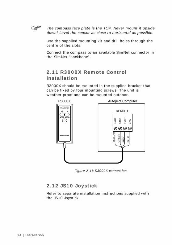
2.11 R3000X Remote Control installation R3000X should be mounted in the supplied bracket that can be fixed by four mounting screws. The unit is weather proof and can be mounted outdoor.
Autopilot ComputerR3000X
REMOTELA
MP
YE
LLO
W
GR
EE
N
RE
D
BLU
E
STB
D
PO
RT
GN
D
Figure 2-18 R3000X connection
2.12 JS10 Joystick Refer to separate installation instructions supplied with the JS10 Joystick.
Installation | 25
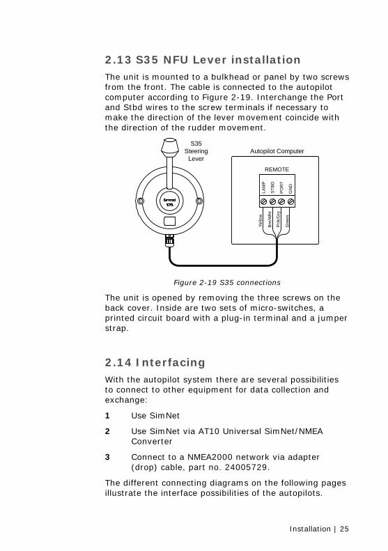
2.13 S35 NFU Lever installation The unit is mounted to a bulkhead or panel by two screws from the front. The cable is connected to the autopilot computer according to Figure 2-19. Interchange the Port and Stbd wires to the screw terminals if necessary to make the direction of the lever movement coincide with the direction of the rudder movement.
Autopilot ComputerS35
SteeringLever
REMOTE
LAM
PYe
llow
Brn
/Wht
Pnk
/Gry
Gre
en
STB
D
PO
RT
GN
D
Figure 2-19 S35 connections
The unit is opened by removing the three screws on the back cover. Inside are two sets of micro-switches, a printed circuit board with a plug-in terminal and a jumper strap.
2.14 Interfacing With the autopilot system there are several possibilities to connect to other equipment for data collection and exchange:
1 Use SimNet
2 Use SimNet via AT10 Universal SimNet/NMEA Converter
3 Connect to a NMEA2000 network via adapter (drop) cable, part no. 24005729.
The different connecting diagrams on the following pages illustrate the interface possibilities of the autopilots.

26 | Installation
2.15 SimNet The SimNet cable system with very small plugs in both ends makes it easy to run the cables, only 10 mm (3/8”) holes are required through panels and bulkheads. The SimNet accessory program contains the necessary items to make a successful installation. Refer to SimNet cables and accessories, page 32.
SimNet network cables
A SimNet unit has one or two yellow SimNet connectors. There are no dedicated “in” or “out” connectors. Route the SimNet cables with Figure 2-20, Figure 2-21 or Figure 2-22 as a guideline. Select cables and accessories from the SimNet accessory program. Connect products with two SimNet connectors in a daisy chain and use drop cables and T-joiners when required. For cable extension in-line cable joiners are available. Total length of SimNet cable installed in a system should not exceed 150 meter (500’).
If you plan to extend your SimNet system in the future it may be advantageous to prepare for it by adding a few T-joiners in central locations. The T-joiners provide easy access to the network and can be replaced with a new product, or the new product can be connected via a drop cable.
The connectors are weather proof according to IP66, when properly installed. All unused SimNet connectors must be fitted with the plastic cap to protect them against dirt and moisture.
SimNet power and termination
The following rules should be observed when installing SimNet.
1 It must have a separate 12VDC power from the battery bus or the circuit breaker board to reduce interference
2 It must not be connected to the supply voltage terminals on the Autopilot Computer.
Installation | 27
3 It will power a SimNet compatible instrument system. Hence SimNet to other equipment can be supplied via the autopilot, see Figure 2-20, Figure 2-21 and Figure 2-22.
4 SimNet must be properly terminated, i.e. unless it is a small system (see Figure 2-20) there must be terminations at each end of the Simrad backbone.
The SimNet network has to be terminated according to the number and type of products connected.
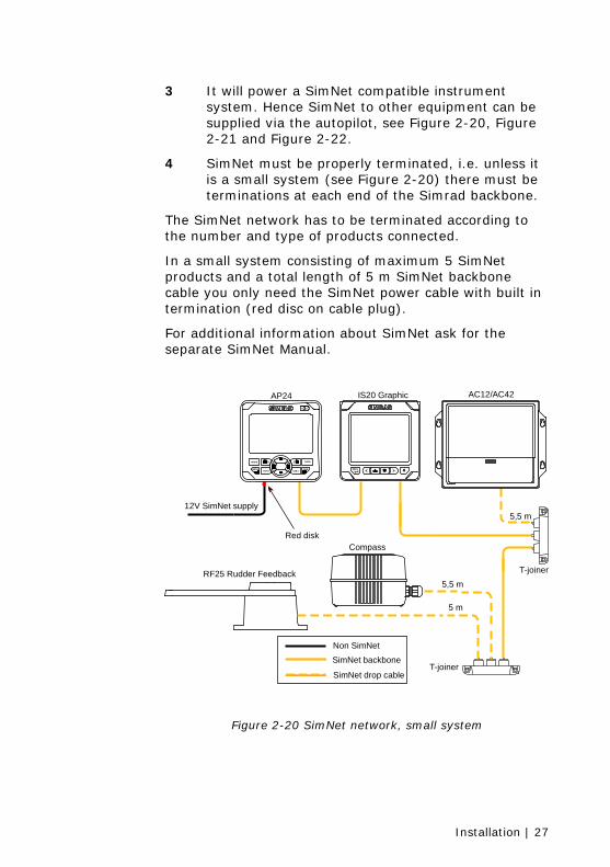
In a small system consisting of maximum 5 SimNet products and a total length of 5 m SimNet backbone cable you only need the SimNet power cable with built in termination (red disc on cable plug).
For additional information about SimNet ask for the separate SimNet Manual.
AP24 IS20 Graphic
12V SimNet supply
Red disk
T-joiner
T-joiner
5,5 m
5,5 m
5 m
Compass
Non SimNetSimNet backbone
SimNet drop cable
24AP
MODE
MENUAUTO STBY
TURN1010
PWR11
RF25 Rudder Feedback
AC12/AC42
Figure 2-20 SimNet network, small system
28 | Installation
AutopilotChart Plotter InstrumentInstrument
Terminationplug
Windtransducer *
T-joiner
T-joiner
Multijoiner
Compass
5,5 m
5,5 m
5,5 m
20 m
/30
m/4
0 m
5,5 m
5 mActivedepthtransducer
AnalogSpeed/Temp
sensor
24AP
MODE
MENUAUTO STBY
TURN1010
PWR11
RF25 Rudder Feedback
12V SimNet supply(SimNet cable without terminator)
Autopilot Computer
Non SimNet
SimNet backbone
SimNet drop cable
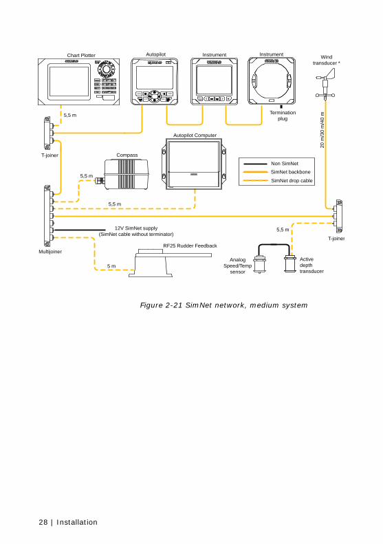
Figure 2-21 SimNet network, medium system
Installation | 29
AP24 AP28
GS10
IS20 Compass IS20 Graphic
Terminationplug
Windtransducer *
Multi-joiner
Multijoiner
Compass5,5 m
20 m
/30
m/4
0 m
5,5 m
5 m
5,5 m
5,5 m
Depth Speed/Temp
RS82
WR20
WB20
RS82Black box
DisplayRemote
24AP
MODE
MENUAUTO STBY
TURN1010
PWR11
RF25 Rudder Feedback12V SimNet supply
(Cable without terminator)
AC12/AC42
Non SimNet
SimNet backbone
SimNet drop cable
SIMRAD RS82
WR20
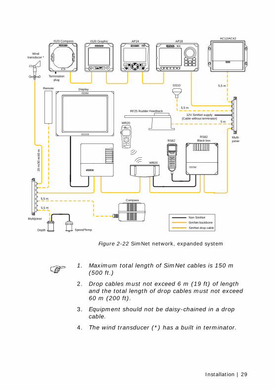
Figure 2-22 SimNet network, expanded system
1. Maximum total length of SimNet cables is 150 m
(500 ft.)
2. Drop cables must not exceed 6 m (19 ft) of length and the total length of drop cables must not exceed 60 m (200 ft).
3. Equipment should not be daisy-chained in a drop cable.
4. The wind transducer (*) has a built in terminator.
30 | Installation
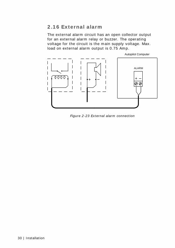
2.16 External alarm The external alarm circuit has an open collector output for an external alarm relay or buzzer. The operating voltage for the circuit is the main supply voltage. Max. load on external alarm output is 0.75 Amp.
++
Autopilot Computer
ALARM
Figure 2-23 External alarm connection
Spare parts list | 31
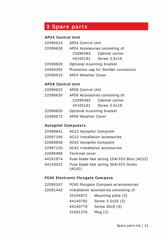
3 Spare parts
AP24 Control Unit
22096614 AP24 Control Unit
22096630 AP24 Accessories consisting of: 22095483 Cabinet corner 44165181 Screw 3,5x19
22096820 Optional mounting bracket
24006355 Protection cap for SimNet connectors
22096515 AP24 Weather Cover
AP28 Control Unit
22096622 AP28 Control Unit
22096630 AP28 Accessories consisting of: 22095483 Cabinet corner 44165181 Screw 3,5x19
22096820 Optional mounting bracket
22096572 AP28 Weather Cover
Autopilot Computers
22089841 AC12 Autopilot Computer
22097166 AC12 Installation accessories
22089858 AC42 Autopilot Computer
22097125 AC42 Installation accessories
22096986 Terminal cover
44161974 Fuse blade fast acting 15A/32V Blue (AC12)
44143022 Fuse blade fast acting 30A/32V Green (AC42)
FC40 Electronic Fluxgate Compass
22090187 FC40 Fluxgate Compass w/accessories
22081442 Installation accessories consisting of:
20104972 Mounting plate (2)
44140762 Screw 3.5x25 (2)
44140770 Screw 30x9 (4)
22081376 Plug (2)
32 | Spare parts list
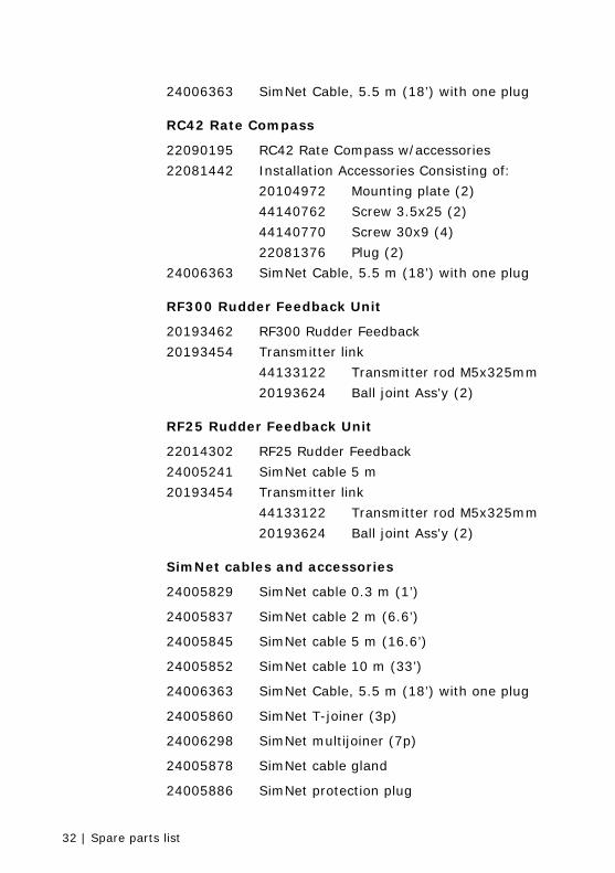
24006363 SimNet Cable, 5.5 m (18’) with one plug
RC42 Rate Compass
22090195 RC42 Rate Compass w/accessories
22081442 Installation Accessories Consisting of:
20104972 Mounting plate (2)
44140762 Screw 3.5x25 (2)
44140770 Screw 30x9 (4)
22081376 Plug (2)
24006363 SimNet Cable, 5.5 m (18’) with one plug
RF300 Rudder Feedback Unit
20193462 RF300 Rudder Feedback
20193454 Transmitter link
44133122 Transmitter rod M5x325mm
20193624 Ball joint Ass'y (2)
RF25 Rudder Feedback Unit
22014302 RF25 Rudder Feedback
24005241 SimNet cable 5 m
20193454 Transmitter link
44133122 Transmitter rod M5x325mm
20193624 Ball joint Ass'y (2)
SimNet cables and accessories
24005829 SimNet cable 0.3 m (1’)
24005837 SimNet cable 2 m (6.6’)
24005845 SimNet cable 5 m (16.6’)
24005852 SimNet cable 10 m (33’)
24006363 SimNet Cable, 5.5 m (18’) with one plug
24005860 SimNet T-joiner (3p)
24006298 SimNet multijoiner (7p)
24005878 SimNet cable gland
24005886 SimNet protection plug
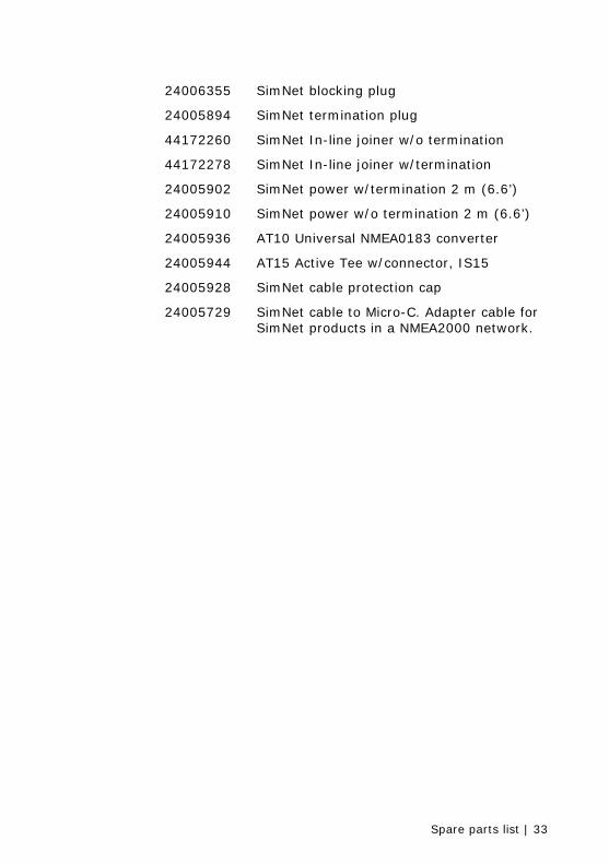
Spare parts list | 33
24006355 SimNet blocking plug
24005894 SimNet termination plug
44172260 SimNet In-line joiner w/o termination
44172278 SimNet In-line joiner w/termination
24005902 SimNet power w/termination 2 m (6.6’)
24005910 SimNet power w/o termination 2 m (6.6’)
24005936 AT10 Universal NMEA0183 converter
24005944 AT15 Active Tee w/connector, IS15
24005928 SimNet cable protection cap
24005729 SimNet cable to Micro-C. Adapter cable for SimNet products in a NMEA2000 network.

34 | Spare parts list
Blank page
Technical specifications | 35
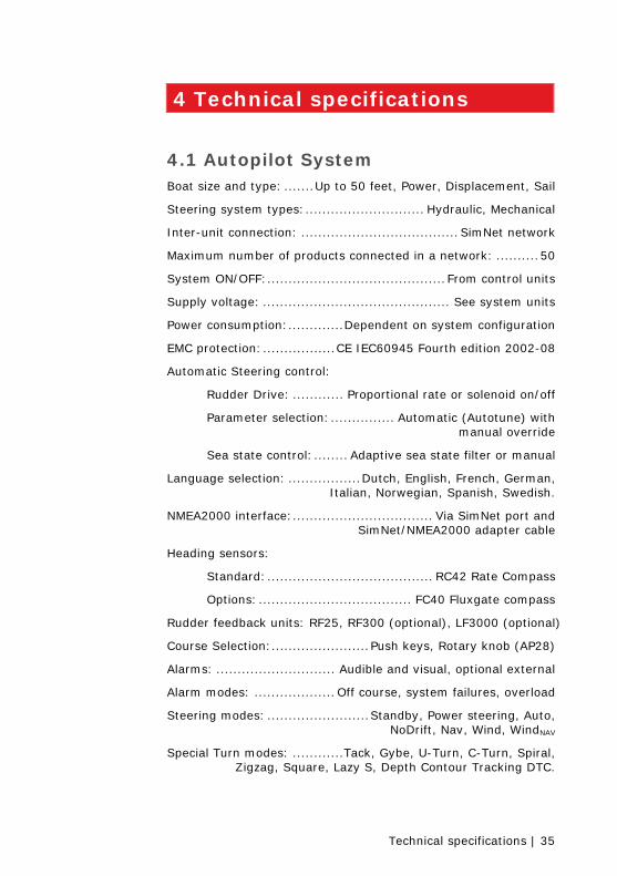
4 Technical specifications
4.1 Autopilot System Boat size and type: .......Up to 50 feet, Power, Displacement, Sail
Steering system types:............................ Hydraulic, Mechanical
Inter-unit connection: ..................................... SimNet network
Maximum number of products connected in a network: ..........50
System ON/OFF:..........................................From control units
Supply voltage: ............................................ See system units
Power consumption:.............Dependent on system configuration
EMC protection:.................CE IEC60945 Fourth edition 2002-08
Automatic Steering control:
Rudder Drive: ............ Proportional rate or solenoid on/off
Parameter selection:............... Automatic (Autotune) with manual override
Sea state control:........ Adaptive sea state filter or manual
Language selection: .................Dutch, English, French, German, Italian, Norwegian, Spanish, Swedish.
NMEA2000 interface:................................. Via SimNet port and SimNet/NMEA2000 adapter cable
Heading sensors:
Standard:....................................... RC42 Rate Compass
Options:.................................... FC40 Fluxgate compass
Rudder feedback units: RF25, RF300 (optional), LF3000 (optional)
Course Selection:.......................Push keys, Rotary knob (AP28)
Alarms: ............................ Audible and visual, optional external
Alarm modes: ...................Off course, system failures, overload
Steering modes: ........................Standby, Power steering, Auto, NoDrift, Nav, Wind, WindNAV
Special Turn modes: ............Tack, Gybe, U-Turn, C-Turn, Spiral, Zigzag, Square, Lazy S, Depth Contour Tracking DTC.
36 | Technical specifications
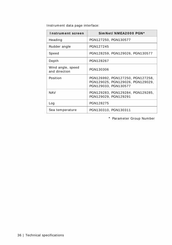
Instrument data page interface:
Instrument screen SimNet/NMEA2000 PGN*
Heading PGN127250, PGN130577
Rudder angle PGN127245
Speed PGN128259, PGN129026, PGN130577
Depth PGN128267
Wind angle, speed and direction
PGN130306
Position PGN126992, PGN127250, PGN127258, PGN129025, PGN129026, PGN129029, PGN129033, PGN130577
NAV PGN129283, PGN129284, PGN129285, PGN129029, PGN129291
Log PGN128275
Sea temperature PGN130310, PGN130311
* Parameter Group Number
Technical specifications | 37
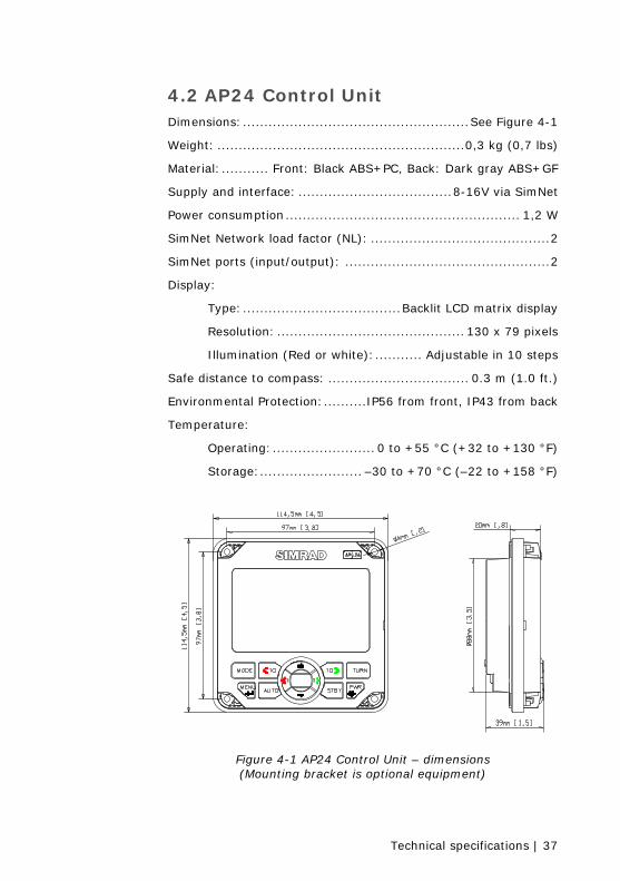
4.2 AP24 Control Unit Dimensions:.....................................................See Figure 4-1
Weight: ..........................................................0,3 kg (0,7 lbs)
Material:........... Front: Black ABS+PC, Back: Dark gray ABS+GF
Supply and interface: ....................................8-16V via SimNet
Power consumption....................................................... 1,2 W
SimNet Network load factor (NL): ..........................................2
SimNet ports (input/output): ................................................2
Display:
Type:.....................................Backlit LCD matrix display
Resolution: ............................................ 130 x 79 pixels
Illumination (Red or white):........... Adjustable in 10 steps
Safe distance to compass: ................................. 0.3 m (1.0 ft.)
Environmental Protection:..........IP56 from front, IP43 from back
Temperature:
Operating:........................ 0 to +55 °C (+32 to +130 °F)
Storage:........................ –30 to +70 °C (–22 to +158 °F)
Figure 4-1 AP24 Control Unit – dimensions (Mounting bracket is optional equipment)
38 | Technical specifications
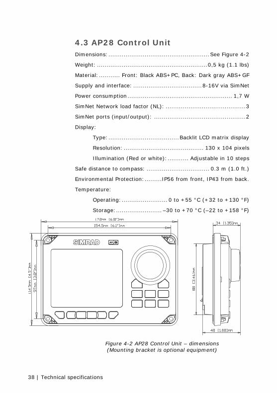
4.3 AP28 Control Unit Dimensions:.....................................................See Figure 4-2
Weight: ..........................................................0,5 kg (1.1 lbs)
Material:........... Front: Black ABS+PC, Back: Dark gray ABS+GF
Supply and interface: ....................................8-16V via SimNet
Power consumption....................................................... 1,7 W
SimNet Network load factor (NL): ..........................................3
SimNet ports (input/output): ................................................2
Display:
Type:.....................................Backlit LCD matrix display
Resolution: .......................................... 130 x 104 pixels
Illumination (Red or white):........... Adjustable in 10 steps
Safe distance to compass: ................................. 0.3 m (1.0 ft.)
Environmental Protection:.........IP56 from front, IP43 from back.
Temperature:
Operating:........................ 0 to +55 °C (+32 to +130 °F)
Storage:........................ –30 to +70 °C (–22 to +158 °F)
Figure 4-2 AP28 Control Unit – dimensions (Mounting bracket is optional equipment)
Technical specifications | 39
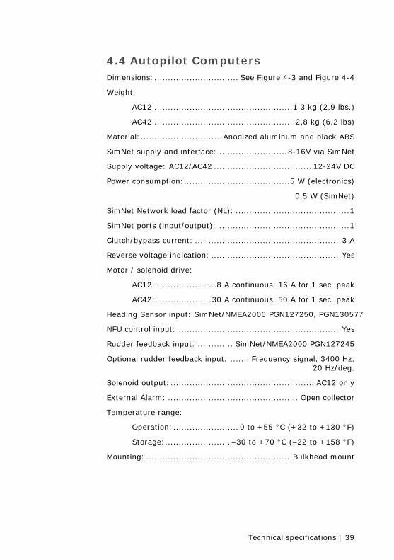
4.4 Autopilot Computers Dimensions:............................... See Figure 4-3 and Figure 4-4
Weight:
AC12 ...................................................1,3 kg (2,9 lbs.)
AC42 ....................................................2,8 kg (6,2 lbs)
Material:..............................Anodized aluminum and black ABS
SimNet supply and interface: .........................8-16V via SimNet
Supply voltage: AC12/AC42 .................................... 12-24V DC
Power consumption:.......................................5 W (electronics)
0,5 W (SimNet)
SimNet Network load factor (NL): ..........................................1
SimNet ports (input/output): ................................................1
Clutch/bypass current: ......................................................3 A
Reverse voltage indication: ................................................Yes
Motor / solenoid drive:
AC12: ......................8 A continuous, 16 A for 1 sec. peak
AC42: ....................30 A continuous, 50 A for 1 sec. peak
Heading Sensor input: SimNet/NMEA2000 PGN127250, PGN130577
NFU control input: ............................................................Yes
Rudder feedback input: ............. SimNet/NMEA2000 PGN127245
Optional rudder feedback input: ....... Frequency signal, 3400 Hz, 20 Hz/deg.
Solenoid output:..................................................... AC12 only
External Alarm: ................................................ Open collector
Temperature range:
Operation:........................ 0 to +55 °C (+32 to +130 °F)
Storage:........................ –30 to +70 °C (–22 to +158 °F)
Mounting: ......................................................Bulkhead mount
40 | Technical specifications
Figure 4-3 AC12 Autopilot Computer - Dimensions
Figure 4-4 AC42 Autopilot Computer – Dimensions
Technical specifications | 41
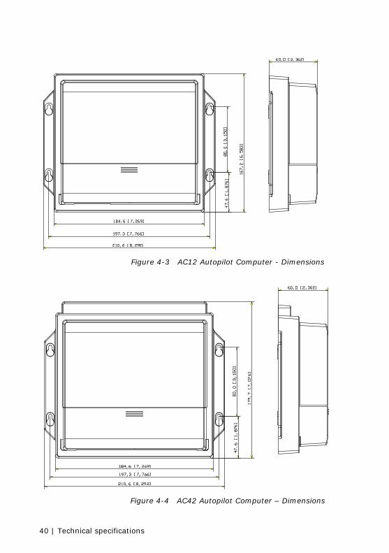
Figure 4-5 AC12/AC42 Cable retainer
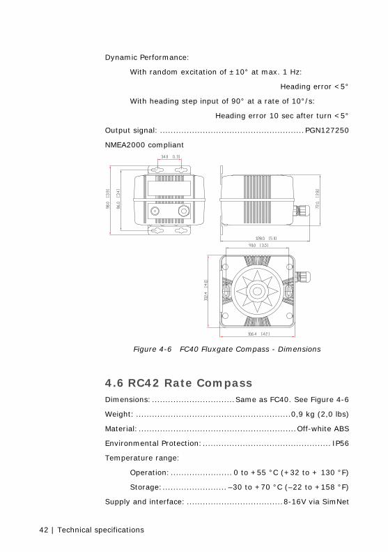
4.5 FC40 Fluxgate Compass Dimensions:.....................................................See Figure 4-6
Weight: ..........................................................0,9 kg (2,0 lbs)
Material:................................................................ Black ABS
Environmental Protection:................................................ IP56
Temperature range:
Operation:....................... 0 to +55 °C (+32 to + 130 °F)
Storage:........................ –30 to +70 °C (–22 to +158 °F)
Supply and interface: ....................................8-16V via SimNet
Power consumption:...................................................... 1,4 W
SimNet Network load factor (NL): ..........................................3
SimNet ports (input/output): ................................................1
Cable supplied:............ 5.5 m (18’) SimNet cable with connector
Mounting: .................................................... Deck or bulkhead
Automatic Performance:
Calibration: ......Automatically activated from control head
Gain control:.............Automatically adjusted continuously
Deviation control:.......................................... Automatic
Static Performance:
Roll/Pitch: ...........................................................± 35°
Accuracy: .......................................± 3° after calibration
Repeatability: .....................................................± 1.0°
42 | Technical specifications
Dynamic Performance:
With random excitation of ±10° at max. 1 Hz:
Heading error <5°
With heading step input of 90° at a rate of 10°/s:
Heading error 10 sec after turn <5°
Output signal: ......................................................PGN127250
NMEA2000 compliant
Figure 4-6 FC40 Fluxgate Compass - Dimensions
4.6 RC42 Rate Compass Dimensions:...............................Same as FC40. See Figure 4-6
Weight: ..........................................................0,9 kg (2,0 lbs)
Material:...........................................................Off-white ABS
Environmental Protection:................................................ IP56
Temperature range:
Operation:....................... 0 to +55 °C (+32 to + 130 °F)
Storage:........................ –30 to +70 °C (–22 to +158 °F)
Supply and interface: ....................................8-16V via SimNet
Technical specifications | 43
Power consumption:...................................................... 1,4 W
SimNet Network load factor (NL): ..........................................3
SimNet ports (input/output): ................................................1
Cable supplied:............ 5.5 m (18’) SimNet cable with connector
Mounting: .................................................... Deck or bulkhead
Automatic Performance:
Calibration: ......Automatically activated from control head
Gain control:.............Automatically adjusted continuously
Deviation control:.......................................... Automatic
Heading output: ............................Rate sensor stabilized
Static Performance:
Roll/Pitch: ...........................................................± 35°
Accuracy: ............................ ± 3 degrees after calibration
Repeatability: .....................................................± 1.0°
Dynamic Performance:
With random excitation of ±10° at max. 1 Hz:
Heading error <2°
With heading step input of 90° at a rate of 10°/s:
Heading error 10 sec after turn <2°
Output signal .......................................... PGN127250, 127251
NMEA2000 compliant
4.7 RF300 Rudder Feedback Dimensions:.............................. See Figure 4-7 and Figure 4-8.
Weight: ..........................................................0,5 kg (1,1 lbs)
Material: .................................................. Arnite T06 200 PBT
Environmental Protection:................................................ IP56
Temperature range:
Operation:..................... –25 to +55 °C (–13 to +130 °F)
Storage:....................... –30 to +70 °C (–22 to + 158 °F)
Mounting: ..........................Horizontal, vertical, or upside down
44 | Technical specifications
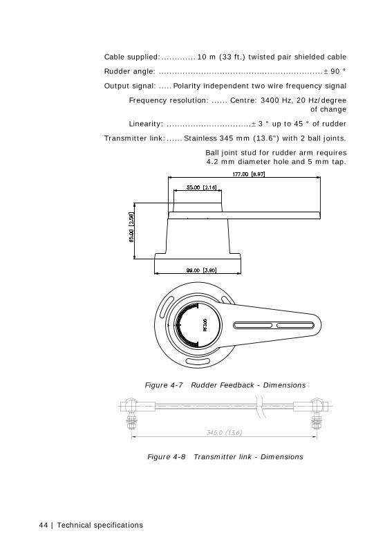
Cable supplied:............. 10 m (33 ft.) twisted pair shielded cable
Rudder angle: ..............................................................± 90 °
Output signal: ..... Polarity independent two wire frequency signal
Frequency resolution: ...... Centre: 3400 Hz, 20 Hz/degree of change
Linearity: ................................± 3 ° up to 45 ° of rudder
Transmitter link:...... Stainless 345 mm (13.6") with 2 ball joints.
Ball joint stud for rudder arm requires 4.2 mm diameter hole and 5 mm tap.
Figure 4-7 Rudder Feedback - Dimensions
Figure 4-8 Transmitter link - Dimensions
Technical specifications | 45
4.8 RF25 Rudder Feedback Dimensions:.............................. See Figure 4-7 and Figure 4-8.
Weight: ..........................................................0,5 kg (1,1 lbs)
Material: .................................................. Arnite T06 200 PBT
Environmental Protection:................................................ IP56
Temperature range:
Operation:..................... –25 to +55 °C (–13 to +130 °F)
Storage:....................... –30 to +70 °C (–22 to + 158 °F)
Mounting: ..........................Horizontal, vertical, or upside down
Supply and interface: ....................................8-16V via SimNet
Power consumption:...................................................... 0,4 W
SimNet Network load factor (NL): ..........................................1
SimNet ports (input/output): ................................................1
Cable supplied:............... 5 m (16’) SimNet cable with connector
Rudder angle: ....................................................±120 degrees
Output signal: .......................... SimNet/NMEA2000 PGN127245
Accuracy: ...................±0.25° within ±5°, otherwise ±0.5°
Repeatability: ......................................................±0.1°
Transmitter link:...... Stainless 345 mm (13.6") with 2 ball joints. Ball joint stud for rudder arm requires 4.2 mm diameter hole and 5 mm tap.
NMEA2000 compliant
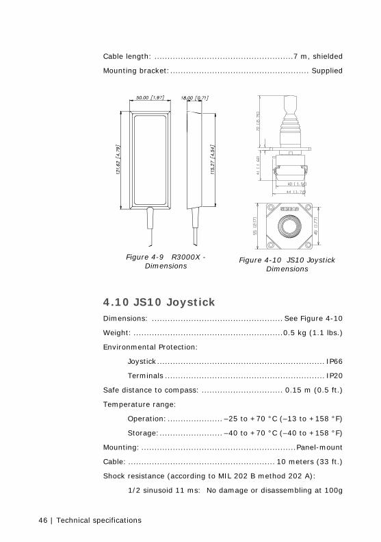
4.9 R3000X Remote Control Dimensions:.....................................................See Figure 4-9
Weight: ..........................................................0,4 kg (0,9 lbs)
Material:.............................................Epoxy coated aluminum
Environmental Protection ................................................. IP56
Safe distance to compass: ............................... 0.15 m (0.5 ft.)
Temperature range:
Operation:..................... –25 to +55 °C (–13 to +130 °F)
Storage:....................... –30 to +70 °C (–22 to + 158 °F)
46 | Technical specifications
Cable length: .....................................................7 m, shielded
Mounting bracket:..................................................... Supplied
Figure 4-9 R3000X - Dimensions
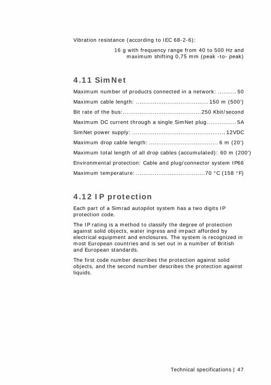
Figure 4-10 JS10 Joystick Dimensions
4.10 JS10 Joystick Dimensions: .................................................. See Figure 4-10
Weight: .........................................................0.5 kg (1.1 lbs.)
Environmental Protection:
Joystick................................................................ IP66
Terminals ............................................................. IP20
Safe distance to compass: ............................... 0.15 m (0.5 ft.)
Temperature range:
Operation:..................... –25 to +70 °C (–13 to +158 °F)
Storage:........................ –40 to +70 °C (–40 to +158 °F)
Mounting: ...........................................................Panel-mount
Cable: ........................................................ 10 meters (33 ft.)
Shock resistance (according to MIL 202 B method 202 A):
1/2 sinusoid 11 ms: No damage or disassembling at 100g
Technical specifications | 47
Vibration resistance (according to IEC 68-2-6):
16 g with frequency range from 40 to 500 Hz and maximum shifting 0,75 mm (peak -to- peak)
4.11 SimNet Maximum number of products connected in a network: ..........50
Maximum cable length: .......................................150 m (500’)
Bit rate of the bus:..........................................250 Kbit/second
Maximum DC current through a single SimNet plug................5A
SimNet power supply: ..................................................12VDC
Maximum drop cable length: ..................................... 6 m (20’)
Maximum total length of all drop cables (accumulated): 60 m (200’)
Environmental protection: Cable and plug/connector system IP66
Maximum temperature: .....................................70 °C (158 °F)
4.12 IP protection Each part of a Simrad autopilot system has a two digits IP protection code.
The IP rating is a method to classify the degree of protection against solid objects, water ingress and impact afforded by electrical equipment and enclosures. The system is recognized in most European countries and is set out in a number of British and European standards.
The first code number describes the protection against solid objects, and the second number describes the protection against liquids.

48 | Technical specifications
FIRST NUMBER Protection against solid objects
SECOND NUMBER Protection against liquids
IP TESTS IP TESTS
0 No protection 0 No protection
1 Protection against solid objects up to 50 mm, e.g. accidental touches by hands.
1 Protected against vertically falling drops of water (e.g. condensation).
2 Protection against solid objects up to 12 mm, e.g. fingers.
2 Protected against direct sprays of water up to 15° from the vertical.
3 Protection against solid objects over 2.5 mm (tools + wires)
3 Protected against sprays to 60° from the vertical.
4 Protection against solid objects over 1 mm (tools + wires + small wires)
4 Protected against water sprayed from any direction.
5 Protection against dust - limited ingress (no harmful deposit)
5 Protected against low pressure jets of water from all directions - limited ingress permitted.
6 Totally protected against dust 6 Protected against strong jets of water, e.g. for use on ship decks - limited ingress permitted.
7 Protected against the effects of immersion between 15 cm and 1 m.
8 Protected against long periods of immersion under pressure.
4.13 AT10 SimNet/NMEA0183 converter
Technical specifications | 49
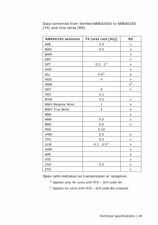
Data converted from SimNet/NMEA2000 to NMEA0183 (TX) and vice versa (RX).
NMEA0183 sentence TX (max rate [Hz]) RX
APB 0.5 x
BWC 0.5 x
BWR x
DBT x
DPT 0.5 11) x
GGA x
GLL 0.52) x
HDG 4 x
HDM x2)
HDT 4 x
HSC 0.1
MTW 0.2 x
MWV Relative Wind 1 x
MWV True Wind 1 x
RMA x
RMB 0.5 x
RMC 0.5 x
RSA 3.33
VHW 0.5 x
VTG 0.5 x
VLW 0.2 0.51) x
VWR x
WPL x
XTE x
ZDA 0.5 x
ZTG x
Open cells indicates no transmission or reception.
1) Applies only for units with P/N – S/N code AA
2) Applies for units with P/N – S/N code BA onwards

50 | Technical specifications

Index | 51
5 Index
A autopilot computer
installation, 11 specifications, 39
C cable
specifications, 11 control unit
specifications, 37, 38
D drive unit
hydraulic pumps, 18 linear drive, 18
E external alarm, 30
F fluxgate compass
specifications, 41
G grounding, 13
I interfacing, 25 IP protection code, 47
N NMEA0183, 49 NMEA2000, 49
P polarity, 12
R remote control
specifications, 45 rudder feedback
installation, 14 specifications, 43, 45
S SimNet, 26 specifications, 35 steering lever
installation, 25 system
specifications, 35
T terminal board, 13
V virtual feedback, 8

52 | Index


