Installation manual for room air conditioner Read this manual before installation and keep it for future reference. Please explain to the user how the product works and refer them to the operation manual. NO.0010553937 HSU-26HEK03/R2(DB)/I HSU-35HEK03/R2(DB)/I HSU-53HEK03/R2(DB)/I HSU-71HEK03/R2(DB)/I HSU-26HEK03/R2(DB)/O HSU-35HEK03/R2(DB)/O HSU-53HEK03/R2(DB)/O HSU-71HEK03/R2(DB)/O
Transcript
Installation manualfor room air conditioner
Read this manual before installation and keep it for future reference.Please explain to the user how the product works and refer them to the operation manual.
Drawing for the installation of indoor and outdoor units p4
Power requirements p3
Electrical connection p6
Indoor unit p5
Outdoor unit p6
3
Preparation
DriverNibblerHacksawHole core drillSpanner (17,19 and 26mm)Gas leakage detector or soap-and-water solutionVacuum pumpTorque wrench (17mm, 22mm, 26mm)Pipe cutterFlaring toolKnifeMeasuring tapeReamerRefrigeration gauges
Install an exclusive circuit for the power.Check the power source voltage is the same as the rating plate.
Indoor UnitThe place chosen to install the indoor unit should be:
Not affected by heat or steam generated in the vicinity, where inlet and outlet of the unit are not blocked or restricted.Where it is possible to drain easily, and where piping can be connected with the outdoor unit.Where conditioned air can be evenly distributed through the whole room.Where there is more than 1m distance from televisions, radios, wireless
are on.
Outdoor UnitThe place chosen to install the outdoor unit should be:
Strong enough to bear the unit, where vibration and noise are not increased.Where discharged air and noise do not cause a nuisance to the neighbours.Where a distance marked
Necessary tools for installation
Selection of installation place
Power source
Accessory parts
Selection of pipe
NOTE: The thickness of the pipe must be at least 0.8mm.
Remote controller (1)
R-03 dry battery (2)
Mounting plate (1)
Plastic cap (4)Ø4X25 Screw (4)
Drain hose (1)
Cushion (4)
Drain-elbow (1)
Pipe supporting plate (1)
Model Liquid pipe (Ø) Gas pipe (Ø)") 9.52mm (3/8")") 9.52mm (3/8")") 12.7mm (1/2")") 15.88mm (5/8")
Power requirements
Model Max rated currentHSU-26HEK03/R2(DB)/O 6.1HSU-35HEK03/R2(DB)/O 6.0HSU-53HEK03/R2(DB)/O 10.5HSU-71HEK03/R2(DB)/O 13.8
Drawing for the installation of indoor and outdoor units
The picture above is just for your reference. Please refer to the actual product purchased.
Optional parts for pipingNon-adhesive tape
Adhesive tape
Saddle (L.S.) with screws
Connecting electric cablefor indoor and outdoor
Drain hose
Heating insulating material
Piping hole cover
A
B
C
D
E
F
G
A and G are supplied parts
pipe length is 2m.
the outdoor unit (Unit:mm)
ModelDimensions
x y zHSU-26HEK03/R2(DB)/O 140 500 256HSU-35HEK03/R2(DB)/O 140 500 256HSU-53HEK03/R2(DB)/O 113.5 583 319.5HSU-71HEK03/R2(DB)/O 113.5 633 340
Arrangement ofpiping directions
More than 20cm
More than 30cm
More than 30cm
More than 60cm
More than 10cm
More than 100cm
More than 10cm
Attention must be paid to the rising up
of drain hose
X Y X
Z
Fixing of outdoor unitFix the unit to concrete or block with
horizontally.
earthquake or strong wind.
unit by attaching a vibration-proof mat.
5
Lid for rightpiping
Lid for under piping pipe
Fix with adhesive tape
Lid for left piping
Heat insulationmaterial
Drain hose
Piping
Pipe supportingplate
Indoor/outdoor electric cable
Hooks mounting plate
mounting plate
Indoor Unit
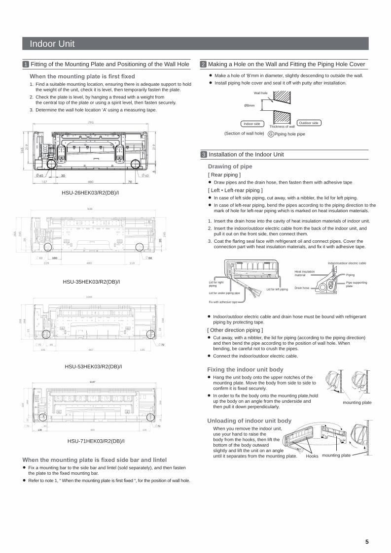
1 Fitting of the Mounting Plate and Positioning of the Wall Hole
1. Find a suitable mounting location, ensuring there is adequate support to hold the weight of the unit, check it is level, then temporarily fasten the plate.
2. Check the plate is level, by hanging a thread with a weight from the central top of the plate or using a spirit level, then fasten securely.
3. Determine the wall hole location ‘A’ using a measuring tape.
Fix a mounting bar to the side bar and lintel (sold separately), and then fasten the plate to the mounting bar.Refer to note 1, “ When the mounting plate is “, for the position of wall hole.
1. Insert the drain hose into the cavity of heat insulation materials of indoor unit.2. Insert the indoor/outdoor electric cable from the back of the indoor unit, and
pull it out on the front side, then connect them.3. Coat the seal face with refrigerant oil and connect pipes. Cover the
connection part with heat insulation materials, and it with adhesive tape.
Indoor/outdoor electric cable and drain hose must be bound with refrigerant piping by protecting tape.
[ Other direction piping ]Cut away, with a nibbler, the lid for piping (according to the piping direction) and then bend the pipe according to the position of wall hole. When bending, be careful not to crush the pipes.Connect the indoor/outdoor electric cable.
Fixing the indoor unit bodyHang the unit body onto the upper notches of the mounting plate. Move the body from side to side to
it is securely.In order to the body onto the mounting plate,holdup the body on an angle from the underside and then pull it down perpendicularly.
Unloading of indoor unit bodyWhen you remove the indoor unit,use your hand to raise the body from the hooks, then lift thebottom of the body outward slightly and lift the unit on an angleuntil it separates from the mounting plate.
Indoor side Outdoor side
ØBmm
Wall hole
Thickness of wall
(Section of wall hole) Piping hole pipeG
2 Making a Hole on the Wall and Fitting the Piping Hole Cover
3 Installation of the Indoor Unit
Make a hole of ‘B’mm in diameter, slightly descending to outside the wall.Install piping hole cover and seal it off with putty after installation.
Drawing of pipe[ Rear piping ]
Draw pipes and the drain hose, then fasten them with adhesive tape
[ Left Left-rear piping ]In case of left side piping, cut away, with a nibbler, the lid for left piping.In case of left-rear piping, bend the pipes according to the piping direction to the mark of hole for left-rear piping which is marked on heat insulation materials.
HSU-35HEK03/R2(DB)/I
HSU-26HEK03/R2(DB)/I
HSU-53HEK03/R2(DB)/I
HSU-71HEK03/R2(DB)/I
260
260
860
320
1147
7070 40
105
12 12
138
1046
667191
268
268
299
70
135
85
13
70
13
938
229
245
480
245562
20
6060 100
110
20
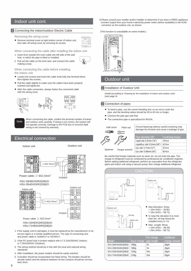
Half union Flare nut
Torque wrenchSpanner
Forced fastening without careful centering maydamage the threads and cause a leakage of gas.
Liquid/Gas side9.52mm(3/8") 42 N.mGas side 12.7mm(1/2") 55N.m
Gas side 15.88mm(5/8") 60 N.mIndoor unit
4G0.75mm2
POWERPower cable: 3G1.5mm2
Outdoor unit
6
2. If the PC board fuse is broken replace with a T.3.15A/250VAC (Indoor) or T.25A/250VAC (Outdoor).
3. The wiring method should be in line with the local and national wiring standards.
4. After installation, the power isolator should be easily reached.5. A breaker should be incorporated into wiring. The breaker should be
all-pole switch and the distance between its two contacts should be not less than 3mm.
To bend a pipe, use the correct bending tool, so as not to crush the pipe, and the bending radius should be 30 to 40 mm or longer.Connect the pipe gas side The connection pipe is specialized for R410A.
Install according to ‘Drawing for the installation of indoor and outdoor units’(see page 4)
Indoor unit cont.
Outdoor unit
Electrical connection
1 Installation of Outdoor Unit
2 Connection of pipes
4 Connecting the indoor/outdoor Electric Cable
Removing the wiring coverRemove terminal cover at right bottom corner of indoor unit, then take off wiring cover by removing its screws.
When connecting the cable after installing the indoor unit1. Insert from outside the room cable into left side of the wall
hole, in which the pipe is fitted or installed.2. Pull out the cable on the front side, and connect the cable
making a loop.
When connecting the cable, the terminal number of indoorand outdoor units carefully. If wiring is not correct, the system will not operate correctly. Damage to the PCB due to incorrectwiring is not covered by warranty.
When connecting the cable before installing the indoor unit
Loosen the screws and insert the cable ends fully into terminal block, then tighten the screws.Pull the cable slightly to make sure the cables have been properly inserted and tightened. After the cable connection, always fasten the connected cable with the wiring cover.
Note
3G2.5mm2
Indoor unitOutdoor unit
4G0.75mm2
12
3(C
)
Power cable:
HSU-26HEK03/R2(DB)/OHSU-35HEK03/R2(DB)/O
HSU-53HEK03/R2(DB)/OHSU-71HEK03/R2(DB)/O
Be careful that foreign materials such as sand, etc. do not enter the pipe. Thecharge of refrigerant must be conducted by professional air conditioner engineer.Before adding additional refrigerant, perform air evacuation from the refrigerantpipes and indoor unit using a vacuum pump, then charge additional refrigerant.
6.Please consult your reseller and/or installer to determine if you have a DRED appliance. Connect output from your home's electricity power meter (where available) to the RJ45 connector on the outdoor unit, as shown.
(This function is unavailable on some models.)
1. If the supply cord is damaged, it must be replaced by the manufacturer or itsservice agent or a similar qualified person. The type of connecting wireand power cable is H05RN-F or H07RN-F.
{POWER
N2
)(
L1
)(
Pipe diameter (Ø) Fastening torqueLiquid side 6.35mm (1/4") 18 N.mLiquid/Gas side 9.52mm (3/8") 42 N.mGas side 12.7mm (1/2") 55 N.mGas side 15.88mm (5/8") 60 N.m
Forced fastening without careful centering maydamage the threads and cause a leakage of gas.
Outdoor unit
Indoor unit
A
B
Outdoor unit
Indoor unitA
B
A
B
Outdoor unit
Indoor unit
Oil trap
CAUTION
Max.Elevation: Amax= 10m (HSU – 26 /35 )= 15m (HSU – 53/71) In case the elevation A is more than 5m, oil trap shoud be installed every 5~7mMax. Length: Bmax= 15m (HSU – 26/35)= 25m (HSU – 53/71)
If the refrigerant of the air conditioner leaks, it is necessary to reclaim allthe refrigerant, then pull a vacuum BEFORE recharging the refrigerant intothe air conditioner according to the amount marked on the name plate.Please do not charge with refrigerant, except as (R410A), orallow air to enter into the cooling circulation system. Otherwise, this may cause abnormal high pressure in the system which may lead to personal injuries or damage to piping.
Outdoor unit cont.
2-way valve
3-way valve
Open 90O
2-way valve3-way valve
Valve rod cap
Valve rod capService port cap
2-way valve3-way valve
7
Step 4Open the 2-way valve to an angle of anticlockwise 90 degrees. After 6 seconds, close the 2-way valve and test for refrigerant gas leakage.
Step 5No gas leakage? If ok, proceed to Step 6.
Step 6Detach the charge hose from the service port, open 2-way valve and 3-way valve. Turn the valve anticlockwise until closed.
Step 7To prevent refrigerant leakage, tighten the service port’s taps and caps to ensure they are sealed.
Step 8After the caps, check for refrigerant gas leakage around the caps.
In case of refrigerant leakage, tighten parts of pipe connections. If leakage stops, then proceed to Step 6.
If this does not stop gas leakage, reclaim all refrigerant from the service port. After and repeating vacuuming on the system, with the
prescribed refrigerant level. Check again for leaks.
Close
Step 3Vacuum for over 15min. Check the (low) gauge which should read -0.1 MPa (-76 cm Hg) at Iow pressure side. After completion of vacuumingthe system, close the low tap on the manifold and turn off the vacuum pump. Check the low side gauge to see if it holds for 1-2 min. If the gauge does not hold pressure, check all the and return to the beginning of Step 3.
Gauge manifold (for R410A)
2-way valve Liquid Side3-way valve Gas Side
Vacuum pump (for R410A)Tube (for R410A)
5 Evacuation Method: Use vacuum pump
Open
Step 1Remove the service port cap from the 3 way valve, the valve caps for the 2 way & 3 way valves. Connect hose to the service port (low) side of the manifold gauge. Then connect the centre hose from the manifold gauge to the vacuum pump.
Step 2Open the tap on the low side of the manifold and operate the vacuum pump. If the gauge (low) reaches a vacuum immediately repeat step 1 above again.
If the drain-elbow is used,please attach it as (Note: Only for heat pump unit.)
Use the same method on indoor unit. Loosen the screws on terminal block and insert the plugs fully into terminal block, then tighten the screws.If wiring is not correct, proper operation can not be carried out and the controller may be damaged.Fix the cable with a clamp.
3 Connection of Electrical Cable
4 Attaching Drain-Elbow4
45
3
11+2= kg
R410A2 kg2=
1=B
C
D
F E
kg
AContains fluorinated greenhouse gasescovered by the Kyoto Protocol
Flare tool for R410A Conventional flare tool
Clutch-type clutch-type(Rigid-type) Wing-nut type (Imperial-type)
A 0~0.5mm 1.0~1.5mm 1.5~2.0mm
It becomeshigh midway.
The gap with theground is too small.
There is the badsmell from a ditch
It waves.The end is imm-ersed in water.
Less than5cm
Flare tooling die 1.Cut pipe 2.Remove burs
3.Insert the flare nut 4.Flare pipe
Lean Damage of flare Partial TooTT outside
Correc It ncorrect
Crack
8
Refrigerant charge label
Check for installation and test run
Please install the drain hose to be always sloping downhill.Examples of incorrect
condensate is carried to outdoor.In case that the attached drain hose is in a room, please apply insulation to drain .
Pipe cutting is carried out with a pipe cutter and burrs must be removed.
Protocol. Do not vent into the atmosphere.Refrigerant type: R410AGWP* value:1975GWP=global warming potential
be adhered in the proximity of the product charging port (e.g. onto the inside of the stop value cover).AB factory refrigerant charge of the product: see unit name plateCD total refrigerant chargeE outdoor unitF refrigerant cylinder and manifold for charging
Please kindly explain to our customers how to operate the unit throughthe instruction manual.
Gas leak from connecting pipe?
Insulation of pipe connecting Pp ?
Are the indoor and outdoor interconnecting cables
Is drainage securely carried out?
Is the earth line securely connected?
Is power source voltage correct?
Is there any noise?
Is the indicator lamp lit?
Are cooling and heating (when in heat pump) performing normally?
Is the operation of room temperature adjustment normal?
Check items for test run Put check mark in boxes
7 Cutting and Flaring Work of Piping
8 On Drainage
The air conditioner must be wired with a dedicated circuit to the distribution board. The protection device should be sized to meet the current requirements of the unit as shown on page 3 and comply with local and national wiring standards.If installing the air conditioner in a moist place, please install an earthleakage breaker.For installation in other places, use a circuit breaker.


![Hypnotica iS Color Changing Series - iLight Technologies...Hypnotica iS Product Profile T 24 RGB D A 0 01 Hypnotica iS 2.66" [67mm] 0.68" [17mm] 0.70" [17mm] 0.40" [10mm] Speci˚cation](https://static.documents.pub/doc/80x56/5eb4a2c06ee3dd53502f8b0a/hypnotica-is-color-changing-series-ilight-technologies-hypnotica-is-product.jpg)


