6

- CONTENTS –
1. INTRODUCTION ............................................................................................................................................................................................................... 2
2. APPLICATIONS .................................................................................................................................................................................................................. 2
3. WARNING and SAFETY ................................................................................................................................................................................................ 2
4. SITE SELECTION ............................................................................................................................................................................................................... 3
5. MODULE TILT ANGLE ................................................................................................................................................................................................... 3
6. INSTALLING SM-SERIES MODULE .......................................................................................................................................................................... 3
7. MODULE WIRING ........................................................................................................................................................................................................... 3
8. MODULE INSTALLATION OPTIONS ........................................................................................................................................................................ 4
2) Roof installation method ............................................................................................................................................................................................ 4
9. GROUNDING ..................................................................................................................................................................................................................... 5
10. BLOCKING DIODES .................................................................................................................................................................................................... 5
11. BYPASS DIODES .......................................................................................................................................................................................................... 5
12. JUNCTION BOX ........................................................................................................................................................................................................... 5
13. MAINTENANCE............................................................................................................................................................................................................ 5
14. SPECIFICATIONS ......................................................................................................................................................................................................... 6
1. INTRODUCTION S-ENERGY offers a wide range of highly efficient and reliable crystalline silicon solar photovoltaic power modules. S-
ENERGY began to extensively research PV technology in 1992 and commenced manufacturing operations in 1994. Since
then, S-ENERGY has supplied several hundred mega watt (MW) worldwide. With years experience and state of the art
technology, S-ENERGY provide the highest quality PV module in a range of sizes designed to meet the requirement of the
most demanding energy and power users worldwide.
2. APPLICATIONS SM series modules are a reliable, virtually maintenance-free direct current (DC) power source, designed to operate most
efficiently in sunlight. SM series modules are ideal for powering remote homes, water pumps, telecommunication system
and many other applications either with or without the use of storage batteries.
3. WARNING and SAFETY Solar modules generate electricity when exposed to light. Arrays of many modules can cause lethal shock and burn hazards.
Only authorized and trained personnel should have access to these modules. To reduce the risk of electrical shock or burns,
modules may be covered with an opaque material during installation to avoid shocks or burns. Do not touch live terminals
with bare hands. Use insulated tools for electrical connections.
PERMIT
▪ Before installing your solar system, contact local authorities to determine the necessary permit, installation and
inspection requirements.
INSTALLATION AND OPERATION
▪ Systems should be installed by qualified personnel only. The system involves electricity, and can be dangerous if the
personnel are not familiar with the appropriate safety procedures.
▪ Do not step on the module.
▪ Although SM series modules are quite rugged, the glass can be broken (and the module will no longer work properly)
if it is dropped or hit by tools or other objects.
▪ Sunlight shall not be concentrated on the module.
▪ The module frame is made of anodized aluminum, and therefore corrosion can occur if the module is subject to a salt-
water environment with contact to a rack of another type of metal. (Electrolysis Corrosion) If required, PVC or stainless
steel washers can be placed between the solar module frame and support structure to prevent this type of corrosion.
▪ SM series module(s) frame must be attached to a support structure by one of the methods described in Section 6,
Installing SM series module(s).
▪ Module support structures that are to be used to support SM series module(s) should be wind rated and approved for
use by the appropriate local and civil codes prior to installation.
FIRE RATING
SM series modules are comprised of a glass front surface, polymeric backskin and possess a Class C fire rating.
GROUNDING
Refer to “Grounding” section.
INSPECTION
Follow the requirements of applicable local and national electrical codes.
BATTERY
When solar modules are used to charge batteries, the battery must be installed in a manner, which will protect the
performance of the system and the safety of its users. Follow the battery manufacturer’s guidelines concerning
installation, operation and maintenance recommendations. In general, the battery (or battery bank) should be away from
the main flow of people and animal traffic. Select a battery site that is protected from sunlight, rain, snow, debris, and is
well ventilated. Most batteries generate hydrogen gas when charging, which can be explosive. Do not light matches or
create sparks near the battery bank. When a battery is installed outdoors, it should be placed in an insulated and ventilated
battery case specifically designed for the purpose.
4. SITE SELECTION In most applications, SM series modules should be installed in a location where they will receive maximum sunlight
throughout the year. In the Northern Hemisphere, the modules should typically face south, and in the southern
Hemisphere, the modules should typically face north. Modules facing 30 degrees away from true South (or North) will lose
approximately 10 to 15 percent of their power output. If the module faces 60 degrees away from true South (or North), the
power loss will be 20 to 30 percent. When choosing a site, avoid trees, buildings or obstructions, which could cast shadows
on the solar modules especially during the winter months when the arc of the sun is lowest over the horizon.
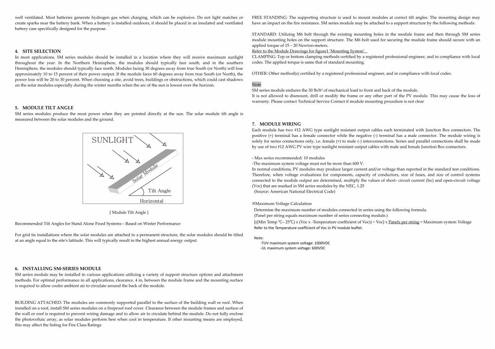
5. MODULE TILT ANGLE SM series modules produce the most power when they are pointed directly at the sun. The solar module tilt angle is
measured between the solar modules and the ground.
[ Module Tilt Angle ]
Recommended Tilt Angles for Stand Alone Fixed Systems—Based on Winter Performance
For grid tie installations where the solar modules are attached to a permanent structure, the solar modules should be tilted
at an angle equal to the site's latitude. This will typically result in the highest annual energy output.
6. INSTALLING SM-SERIES MODULE SM series module may be installed in various applications utilizing a variety of support structure options and attachment
methods. For optimal performance in all applications, clearance, 4 in, between the module frame and the mounting surface
is required to allow cooler ambient air to circulate around the back of the module.
BUILDING ATTACHED: The modules are commonly supported parallel to the surface of the building wall or roof. When
installed on a roof, install SM series modules on a fireproof roof cover. Clearance between the module frames and surface of
the wall or roof is required to prevent wiring damage and to allow air to circulate behind the module. Do not fully enclose
the photovoltaic array, as solar modules perform best when cool in temperature. If other mounting means are employed,
this may affect the listing for Fire Class Ratings
FREE STANDING: The supporting structure is used to mount modules at correct tilt angles. The mounting design may
have an impact on the fire resistance. SM series module may be attached to a support structure by the following methods:
STANDARD: Utilizing M6 bolt through the existing mounting holes in the module frame and then through SM series
module mounting holes on the support structure. The M6 bolt used for securing the module frame should secure with an
applied torque of 15 ~ 20 Newton-meters.
Refer to the Module Drawings for figure1 ‘Mounting System’.
CLAMPING: Top or bottom clamping methods certified by a registered professional engineer, and in compliance with local
codes. The applied torque is same that of standard mounting.
OTHER: Other method(s) certified by a registered professional engineer, and in compliance with local codes.
Note
SM series module endures the 30 lb/ft2 of mechanical load to front and back of the module.
It is not allowed to dismount, drill or modify the frame or any other part of the PV module. This may cause the loss of
warranty. Please contact Technical Service Contact if module mounting procedure is not clear
7. MODULE WIRING Each module has two #12 AWG type sunlight resistant output cables each terminated with Junction Box connectors. The
positive (+) terminal has a female connector while the negative (-) terminal has a male connector. The module wiring is
solely for series connections only, i.e. female (+) to male (-) interconnections. Series and parallel connections shall be made
by use of two #12 AWG PV wire type sunlight resistant output cables with male and female Junction Box connectors.
- Max series recommended: 10 modules
-The maximum system voltage must not be more than 600 V.
In normal conditions, PV modules may produce larger current and/or voltage than reported in the standard test conditions.
Therefore, when voltage evaluations for components, capacity of conductors, size of fuses, and size of control systems
connected to the module output are determined, multiply the values of short- circuit current (Isc) and open-circuit voltage
(Voc) that are marked in SM series modules by the NEC, 1.25
(Source: American National Electrical Code)
※Maximum Voltage Calculation
Determine the maximum number of modules connected in series using the following formula.
(Panel per string equals maximum number of series connecting module.)
[((Min Temp ℃– 25℃) x (Voc x -Temperature coefficient of Voc)) + Voc] x Panels per string = Maximum system Voltage
Refer to the Temperature coefficient of Voc in PV module leaflet.
Note: -TUV maximum system voltage: 1000VDC -UL maximum system voltage: 600VDC

8. MODULE INSTALLATION OPTIONS Modules should be mounted using installer approved clamps over the front side of the module OR with specified bolts
through the mounting holes.
1) Mounting Position (Frame hole dimension)
Hole Position Dimension
54Series 60series 72series
A 250 300 350
B 455 505 555
C 1505 1665 1985
D 999 999 999
E 951.5 951.5 951.5
F 1384.0 1428.1 1598.9 Unit: mm
Mounting Hole Size:
2) Roof installation method
- Modules should be Installed as the following case 1(width installation) or case 2 (length installation)
Case 1 (Width installation) Case 2 (Length installation)
Roof in
stallation m
eth
od
Mountin
g co
nfig
ura
tions
Unit: mm
Unit: mm
3) Clamp mounting method.
- Clamps should be applied, such as the following table.
- Mounting position: Refer to mounting configurations
Clamp detail
Torque: 10 ~ 12.5N.m
4) Hole mounting method
- If using bolts, eight mounting holes are provided on the rear side of the module frame
- Use M6 stainless steel bolt stack with two Plane washers and a Spring washer as shown the following table.
Note: The Mounting Bolt and Nut must tighten the exact location (Mounting Hole). Otherwise, The Mounted Module could
break on the operation
Clamp detail
Torque: 4 ~ 5.2N.m

9. GROUNDING Before installing your solar system, contact local authorities to determine the necessary grounding. Attach all module
frames to an earth ground in accordance with the National Electrical Code (NEC 250). Model installed in Canada shall be in
accordance with CSA C22.1, Safety Standard for Electrical Installations, Canadian Electrical Code, Part 1. Proper grounding
is achieved by connecting the module frame(s) and structural members contiguously one to another using a suitable
"grounding conductor". The grounding conductor, or strap, may be copper material acceptable for use as an electrical
conductor per NEC. The grounding conductor must then make a connection to earth using a suitable earth ground
electrode. Ensure positive electrical contact through the anodizing on the module's frame by utilizing one of the following
grounding methods.
The Grounding method
1) Standard Grounding
LUG TYPE GROUNDING SYSTEM HOLE TYPE GROUNDING SYSTEM
Grounding Hole: 4Ø
Bolt: M4XL25
Nut: M4
Washer: M4 type
Torque: 1 ~ 2N.m.
Grounding Wire: 12 AWG
10. BLOCKING DIODES In systems utilizing a battery, blocking diodes are typically placed between the battery and the solar module output to
prevent battery discharge at night. SM series modules are made of polycrystalline cells with high electrical “back flow”
resistance to nighttime battery discharging. As a result, SM series modules do not contain a blocking diode when shipped
from the factory. Most PV charge regulators and inverter incorporate nighttime disconnect feature, however.
11. BYPASS DIODES Partial shading of an individual module in a source circuit string (i.e. two or more modules connected in series) can cause a
reverse voltage across the shaded cells within the module. Module output current is then forced through the shaded area by
the remaining illuminated cells and other solar modules in series with the partially shaded module(s). The current forced
through the shaded cells within the module (or modules) causes additional module heating and severe loss of power. All
SM series modules are supplied with factory installed (non user serviceable) bypass diodes. The purpose of bypass diodes
is to provide a low-resistance current path around the shaded cells, thereby minimizing module heating and array current
losses.
The solar modules employ bypass diodes that have:
▪ Rated Average Forward Current [IF(AV), 15A] Above maximum system current at highest module operating temperature.
▪ Rated Repetitive Peak Reverse Voltage [VRRM] above maximum system voltage at lowest module operating temperature.
12. JUNCTION BOX A PV module is equipped with plus and minus connectors and a junction box with bypass diodes.
Each connector is designed for one polarity, respectively. (On the junction box, the polarity is clearly marked.
Junction box drawing
- IP Protection: IP65
- Rated Voltage: TUV/ 1000VDC, UL/600VDC
- Rated of current: 15A
- Terminal material: Tinned copper
- Conducting: 4 pole
- Connector: YS-254 and YS-255 (Yukita Electric Wire)
- Wire: Copper, PV wire type 12AWG(4.0mm2), insulated for a minimum of 90 ℃
- Using Bypass diode No.: 3EA
13. MAINTENANCE SM series modules are designed for long life and require very little maintenance. Under most weather conditions, normal
rainfall is sufficient to keep the module glass surface clean. If dirt build-up becomes excessive, clean the glass surface only
with a soft cloth using mild detergent and water. USE CAUTION WHEN CLEANING THE BACK SURFACE OF THE
MODULE TO AVOID PENETRATING BACK SHEET. Modules that are mounted flat (0° tilt angle) should be cleaned more
often, as they will not "self clean" as effectively as modules mounted at a 15 tilt or greater. Once a year, check the general
condition of the wiring and check to be sure that mounting hardware is tight. Loose connections will result in a damaged
module or array.

14. SPECIFICATIONS Typical module production may result in a maximum power from 3% higher to 3% lower than Rated Power (Pmax). Under
certain conditions, a photovoltaic module may produce more voltage and current than reported at Standard Test
Conditions (STC). Refer to Section 690.8 of the National Electrical Code for guidance in series string sizing and choosing
over current protection.
Electrical Characteristics:@ STC
MODULE TYPE SM-240 ~ 255PC8
Pmax (W) 240W 245W 250W 255W
Vpm (V) 30.0V 30.4V 30.8V 30.8V
Ipm (A) 8.02A 8.08A 8.14A 8.28A
Isc (A) 8.58A 8.63A 8.67A 8.82A
Voc (V) 37.3V 37.4V 37.5V 37.9V
No. of cells 60 Maximum System
Voltage (VDC) UL 600 V, TUV 1000V
Bypass Diode Characteristics
Diode Number 3 Series Fuse Rating
(Amps) 15 A
Length (mm) 1665
Width (mm) 999
Depth (mm) 50
Weight (kg) 20
Electrical Characteristics:@ STC
MODULE TYPE SM-280 ~ 305PC8
Pmax (W) 280W 285W 290W 295W 300W 305W
Vpm (V) 35.8V 35.9V 36.2V 36.3V 36.3V 36.5V
Ipm (A) 7.84A 7.95A 8.02A 8.14A 8.27A 8.36A
Isc (A) 8.45A 8.56A 8.58A 8.67A 8.85A 8.92A
Voc (V) 44.3V 44.5V 44.7V 45.0V 45.1V 45.6V
No. of cells 72 Maximum System
Voltage (VDC) UL 600 V, TUV 1000V
Bypass Diode Characteristics
Diode Number 3 Series Fuse Rating
(Amps) 15 A
Length (mm) 1985
Width (mm) 999
Depth (mm) 50
Weight (kg) 23
NOTES
(1) Standard Test Conditions of irradiance of 1000 W/m², spectrum of 1.5 air mass, and cell temperature of 25 ℃.
(2) See module drawing for mounting and grounding hole locations.
(3) Modules are Application Class A
Installation manual subject to change without prior notice.
S-ENERGY reserves the right of final interpretation and revision of this installation manual.
All modules are manufactured by
S-ENERGY Co., Ltd www.s-energy.com
3rd FL, Miraeasset Venture tower 685, Sampyeong-dong, Bundang-gu, Seongnam-si, Gyenggi, 463-400 Republic of KOREA
Tel. +82 70 4339 7100 Fax. +82 70 4339 7199 Mail. [email protected]


