Page 1 Installation Manual for the Kit MyHook 230V Double Swing Gate Automation For more information on GateMotors full line of automatic gate openers and access controls visit our website at www.gatemotors.co.uk Phone Sales Lines UK: 01202 717191 Outside UK: (+44)1202 717191 Phone Technical Lines UK: 0905 235 1700* (service available 8:30am to 5:30pm Monday to Friday only, closed Weekends and Public Holidays) ROI: 156 099 9667** (service available 8:30am to 5:30pm Monday to Friday only, closed Weekends and Public Holidays) Email: [email protected]*UK calls to this number are billed by the second and cost £1.02 per minute from a standard landline; other networks charges may also apply. **IRISH calls to this number are billed by the second and cost €1.25 per minute from a standard landline; other networks charges may also apply. Service is provided by Digital Select Ltd, 271 Regent Street, London, W1B 2ES whose helpline number is 0844 448 0165 Trading address: GateMotors UK, Unit 16c, Chalwyn Industrial Estate, St. Clements Road, Poole, Dorset. BH12 4PE. GateMotors is the trading name of Screwjack Limited - registered office at 21 Oxford Road, Bournemouth, Dorset. BH8 8ET. Registered # is 4287804, VAT #:785 3450 06
Transcript
Page 1
Installation Manual for the Kit MyHook 230V Double Swing Gate Automation
For more information on GateMotors full line of automatic gate openers and access controls visit our website at www.gatemotors.co.uk
Phone Sales Lines UK: 01202 717191 Outside UK: (+44)1202 717191 Phone Technical Lines UK: 0905 235 1700* (service available 8:30am to 5:30pm Monday to Friday only, closed Weekends and Public Holidays) ROI: 156 099 9667** (service available 8:30am to 5:30pm Monday to Friday only, closed Weekends and Public Holidays) Email: [email protected] *UK calls to this number are billed by the second and cost £1.02 per minute from a standard landline; other networks charges may also apply. **IRISH calls to this number are billed by the second and cost €1.25 per minute from a standard landline; other networks charges may also apply. Service is provided by Digital Select Ltd, 271 Regent Street, London, W1B 2ES whose helpline number is 0844 448 0165
Trading address: GateMotors UK, Unit 16c, Chalwyn Industrial Estate, St. Clements Road, Poole, Dorset. BH12 4PE. GateMotors is the trading name of Screwjack Limited - registered office at 21 Oxford Road, Bournemouth, Dorset. BH8 8ET. Registered # is 4287804, VAT #:785 3450 06
Thank you for purchasing the Kit MyHook 230v Double Swing Gate automation. The gate kit is designed to be a “do-it-yourself” automatic gate opener kit. When correctly installed and properly used, your GateMotors Kit Simply 230v Double Swing Gate automation will give you many years of reliable service. Please read the following information to enable you to properly install your gate automation system. The Kit MyHook 230v Double Swing Gate automation is designed for installation on a pull-to-open sliding gate (gates that open from left to right or right to left). The motors can be used on vinyl, aluminium, farm tube and wrought iron gates. The Kit MyHook 230v Double Swing Gate automation accommodates extra transmitters, digital keypads, push buttons, automatic gate locks (additional MEL interface required), and other access control products listed on GateMotors website. The optional accessories are available through our website www.gatemotors.co.uk. GateMotors popular accessories are featured at the end of this installation guide with full details available from the GateMotors website and upon request.
Because automatic gate openers produce high levels of force, consumers need to know the potential hazards
associated with improperly designed, installed, and maintained automated gate opener systems. Keep in mind
that the gate opener is just one component of the total gate operating system. Each component must work in
unison to provide convenience, security, and safety.
This manual contains various safety precautions and warnings for the consumer. Because there are many possible applications of the gate opener, the safety precautions and warnings contained in this manual cannot be completely exhaustive in nature. They do, however, provide an overview of the safe design, installation, and use of this product. Carefully read and follow all safety precautions, warnings and installation instructions to ensure the safe system design, installation and use of this product. Precautions and warnings in this manual are identified with this warning symbol. The symbol identifies conditions that can result in damage to the opener or its components, serious injury, or death. Because GateMotors automatic gate openers are only part of the total gate operating system (as intercoms, push button switches and GSM switches etc. Can be added to complete an “operating system”), it is the responsibility of the end user to ensure that the total system is safe for its intended use.
For The End User
A. WARNING: To reduce the risk of injury or death:
A1. Read and follow all instructions. Failure to meet the requirements set forth in the instruction manual could cause severe injury and/or death, for which the manufacturer cannot be held responsible.
A2. When designing a system that will be entered from a main road or main thoroughfare, make sure the
system is placed far enough from the road to prevent traffic congestion
A3. The gate must be installed in a location that provides adequate clearance between it an adjacent structure(s) when opening and closing to reduce risk of entrapment / crushing.
B. Before installing the gate automation:
B1. Make sure the gate has been properly installed and can slide freely. The gate automation is designed to move the gate so you do not have to. Repair or replace all worn or damaged gate hardware prior to installation. A freely moving gate will require less force to operate and will enhance the performance of the opener and safety devices used with the system.
B2. Review the operation of the system to become familiar with its safety features. Understand how to
disconnect the opener for manual operation in the event of power failure and accidents. (SEE PAGE 14)
B3. The gate opener is intended for vehicular gates ONLY.
B4. Always keep people and objects away from the gate and its area of travel.
No one should cross the path of a moving gate.
Page 5
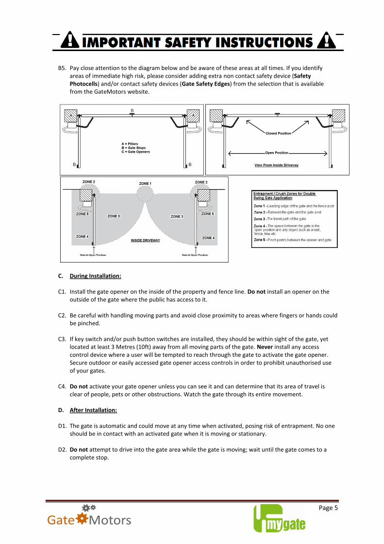
B5. Pay close attention to the diagram below and be aware of these areas at all times. If you identify
areas of immediate high risk, please consider adding extra non contact safety device (Safety Photocells) and/or contact safety devices (Gate Safety Edges) from the selection that is available from the GateMotors website.
C. During Installation:
C1. Install the gate opener on the inside of the property and fence line. Do not install an opener on the outside of the gate where the public has access to it.
C2. Be careful with handling moving parts and avoid close proximity to areas where fingers or hands could
be pinched. C3. If key switch and/or push button switches are installed, they should be within sight of the gate, yet
located at least 3 Metres (10ft) away from all moving parts of the gate. Never install any access control device where a user will be tempted to reach through the gate to activate the gate opener. Secure outdoor or easily accessed gate opener access controls in order to prohibit unauthorised use of your gates.
C4. Do not activate your gate opener unless you can see it and can determine that its area of travel is
clear of people, pets or other obstructions. Watch the gate through its entire movement. D. After Installation:
D1. The gate is automatic and could move at any time when activated, posing risk of entrapment. No one
should be in contact with an activated gate when it is moving or stationary. D2. Do not attempt to drive into the gate area while the gate is moving; wait until the gate comes to a
complete stop.
Page 6
D3. Do not attempt to “beat the gate” while the gate is closing. This is extremely dangerous. D4. Do not allow children or pets near your gate. Never let children operate or play with gate controls.
Keep the remote controls away from children and unauthorised users; store controls where children and unauthorised users cannot obtain access to them.
D5. To operate this equipment safely, YOU must know how to disconnect the opener for manual gate
operation (see page 14). If you have read the instructions and still do not understand how to disconnect the opener, contact GateMotors Technical Department immediately for assistance.
D6. Keep the gate and gate opener regularly maintained. Always turn power to the control board OFF
before performing any maintenance. Regularly grease the gate hinges and the motors triangular mounting bracket pivot point. Clean the push-pull ram arm tube with a soft cloth and then wipe with liquid Paraffin. This ensures clean, smooth operation of your gate automation system.
IMPORTANT: Save these safety instructions. Make sure everyone who is using or will be around the gate and gate openers are aware of the dangers associated with gate automation. In the event you sell the property with the gate opener or sell the gate opener, provide a copy of this instruction guide to the new owner.
Should you lose or misplace this manual, a copy can be obtained by downloading one from the GateMotors website (www.gatemotors.co.uk) or by contacting GateMotors by calling on 01202 717191 for the UK customers or (+44)1202717191 for international customers.
Working Temperature Range . -20 to +55 Degrees Celsius
Leaf's Maximum Length 2M
Leaf's Maximum Weight 250kg
Maximum Opening Angle (degrees) 130
90 Degree Angle Opening Time (sec) 18
Duty Cycle 40%
Kit MyHook 230v Dimensions
Page 8
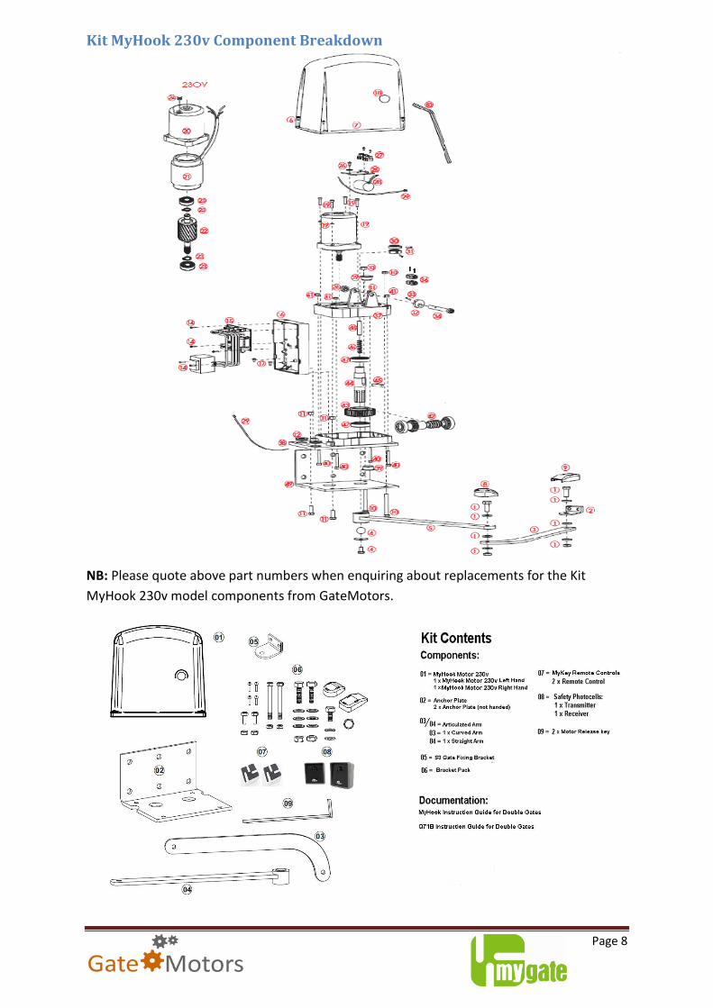
Kit MyHook 230v Component Breakdown
NB: Please quote above part numbers when enquiring about replacements for the Kit
MyHook 230v model components from GateMotors.
Page 9
Kit MyHook Bracket Pack Contents
Kit MyHook - Before Installation.....
Tools Needed: Tape Measure
Power Drill
Adjustable wrench
Hacksaw or Heavy Duty Bolt Cutters
Small (flat head) screwdriver
Small (Pozi Drive) Phillips screwdriver
Wire Strippers
You may also need these items before you begin the installation (Some of these items can be found on GateMotors website): Low voltage wire This will need to be run from the control board to the photocells (transmitter and receiver) and for the key switch (optional to fit). 3 Core 230v Armoured Cable This will be used to transport 230v power from the house to the gate control board. The size of the cable will vary depending on the length. See table for more details:
3 Core armoured cable, swa
< 15m > 15m > 100m > 200m
1.5mm² •
2.5mm² •
4mm² •
6mm² •
0.75mm SWA Alarm Cable / CAT 5 Cable (low voltage cable) This will be used to transport power and switching signals from the photocell units to the control board. PVC Conduit To encase power cables / low voltage cables that are running between the house and the control board and any cables that are to be laid across your driveway.
Page 10
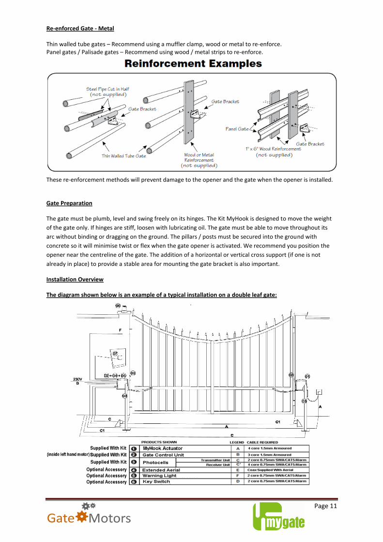
Surge Protection A form of circuit breaker should be fitted between the house and the main gate to protect both the gate control board and the house main fuse box from any power surges that may be experienced. Fence Post Re-enforcement If your fence post / pillars are less than 6” in diameter or 6” square should be made of metal instead of wood so that it can remain stable while the opener is moving the gate – if this is not viable, the post may need to be re-enforced to sustain the torque force produced by the gate opener. The curved design of the post bracket works well for installations on round and square posts. Because the post bracket carries the entire thrust of the active opener, firm sturdy anchored bolts should be used in conjunction. Re-enforced Gate - Wooden
To automate wooden gate, the thickness of the gate should be no less than 70mm and/or have a box boarder supporting frame, especially if the gate is solid not barred – illustrated left. This distributes the torque force produced by the motor and protects the gate from potential damage. (Model shown Kit MyDiamond for illustration purpose only)
Re-enforced Gate – Wooden “Field” barred gate
To automate wooden gate, the thickness of the gate should be no less than 70mm and have a supporting frame beam diagonally across the leaf - illustrated left. This distributes the torque force produced by the motor and protects the gate from potential damage. In this instance, the MyHook motor arm can be directly bolted to the gate, shown left.
Page 11
Re-enforced Gate - Metal Thin walled tube gates – Recommend using a muffler clamp, wood or metal to re-enforce. Panel gates / Palisade gates – Recommend using wood / metal strips to re-enforce.
These re-enforcement methods will prevent damage to the opener and the gate when the opener is installed.
Gate Preparation
The gate must be plumb, level and swing freely on its hinges. The Kit MyHook is designed to move the weight
of the gate only. If hinges are stiff, loosen with lubricating oil. The gate must be able to move throughout its
arc without binding or dragging on the ground. The pillars / posts must be secured into the ground with
concrete so it will minimise twist or flex when the gate opener is activated. We recommend you position the
opener near the centreline of the gate. The addition of a horizontal or vertical cross support (if one is not
already in place) to provide a stable area for mounting the gate bracket is also important.
Installation Overview
The diagram shown below is an example of a typical installation on a double leaf gate:
Page 12
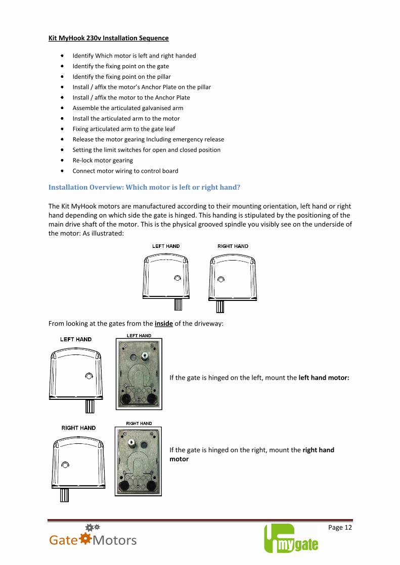
Kit MyHook 230v Installation Sequence
Identify Which motor is left and right handed
Identify the fixing point on the gate
Identify the fixing point on the pillar
Install / affix the motor’s Anchor Plate on the pillar
Install / affix the motor to the Anchor Plate
Assemble the articulated galvanised arm
Install the articulated arm to the motor
Fixing articulated arm to the gate leaf
Release the motor gearing Including emergency release
Setting the limit switches for open and closed position
Re-lock motor gearing
Connect motor wiring to control board
Installation Overview: Which motor is left or right hand?
The Kit MyHook motors are manufactured according to their mounting orientation, left hand or right hand depending on which side the gate is hinged. This handing is stipulated by the positioning of the main drive shaft of the motor. This is the physical grooved spindle you visibly see on the underside of the motor: As illustrated:
From looking at the gates from the inside of the driveway: If the gate is hinged on the left, mount the left hand motor:
If the gate is hinged on the right, mount the right hand motor
Page 13
Another quick way to tell the two hands apart is to lift up the cover of each motor and identify the control board for the gate automation. The control board is always housed in the left hand motor:
The control board comes pre-wired for the left hand motor. Later in the guide we will be
covering how to connect the right hand motor to the control board.
Identifying the fixing point on the gate
Identify the Fixing Point on the Gate
The above connection points to the gate are suggested fixing points. This is based according to the gates shape and the fixing possibilities:
a) If the gate leaf is large in height and width, you can position the motors connecting arm on the gate at any height with no restriction.
b) If the gate leaf is light in weight, it is necessary to place the motors connecting arm on the gate as centrally as possible in order to push and pull the gate effectively, with no shaking and no distorting.
Page 14
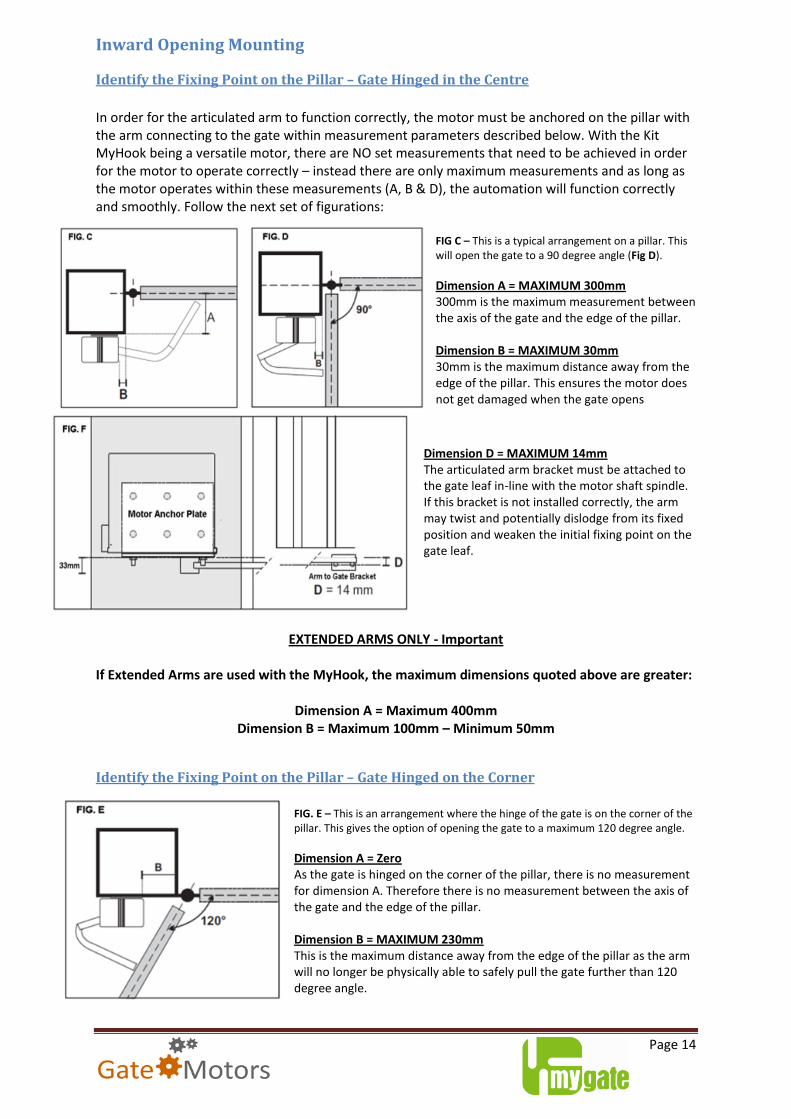
Inward Opening Mounting
Identify the Fixing Point on the Pillar – Gate Hinged in the Centre
In order for the articulated arm to function correctly, the motor must be anchored on the pillar with the arm connecting to the gate within measurement parameters described below. With the Kit MyHook being a versatile motor, there are NO set measurements that need to be achieved in order for the motor to operate correctly – instead there are only maximum measurements and as long as the motor operates within these measurements (A, B & D), the automation will function correctly and smoothly. Follow the next set of figurations:
FIG C – This is a typical arrangement on a pillar. This will open the gate to a 90 degree angle (Fig D).
Dimension A = MAXIMUM 300mm 300mm is the maximum measurement between the axis of the gate and the edge of the pillar. Dimension B = MAXIMUM 30mm 30mm is the maximum distance away from the edge of the pillar. This ensures the motor does not get damaged when the gate opens
Dimension D = MAXIMUM 14mm The articulated arm bracket must be attached to the gate leaf in-line with the motor shaft spindle. If this bracket is not installed correctly, the arm may twist and potentially dislodge from its fixed position and weaken the initial fixing point on the gate leaf.
EXTENDED ARMS ONLY - Important
If Extended Arms are used with the MyHook, the maximum dimensions quoted above are greater:
Dimension A = Maximum 400mm
Dimension B = Maximum 100mm – Minimum 50mm
Identify the Fixing Point on the Pillar – Gate Hinged on the Corner
FIG. E – This is an arrangement where the hinge of the gate is on the corner of the pillar. This gives the option of opening the gate to a maximum 120 degree angle.
Dimension A = Zero As the gate is hinged on the corner of the pillar, there is no measurement for dimension A. Therefore there is no measurement between the axis of the gate and the edge of the pillar. Dimension B = MAXIMUM 230mm This is the maximum distance away from the edge of the pillar as the arm will no longer be physically able to safely pull the gate further than 120 degree angle.
Page 15
Dimension D = MAXIMUM 14mm FIG.F - The articulated arm bracket must be attached to the gate leaf in-line with the motor shaft spindle. If this bracket is not installed correctly, the arm may twist and potentially dislodge from its fixed position and weaken the initial fixing point on the gate leaf.
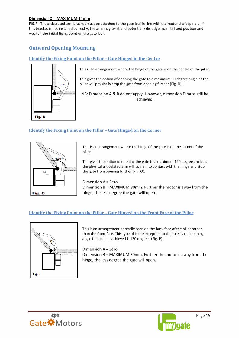
Outward Opening Mounting
Identify the Fixing Point on the Pillar – Gate Hinged in the Centre
This is an arrangement where the hinge of the gate is on the centre of the pillar. This gives the option of opening the gate to a maximum 90 degree angle as the pillar will physically stop the gate from opening further (Fig. N).
NB: Dimension A & B do not apply. However, dimension D must still be achieved.
Identify the Fixing Point on the Pillar – Gate Hinged on the Corner
This is an arrangement where the hinge of the gate is on the corner of the pillar. This gives the option of opening the gate to a maximum 120 degree angle as the physical articulated arm will come into contact with the hinge and stop the gate from opening further (Fig. O).
Dimension A = Zero Dimension B = MAXIMUM 80mm. Further the motor is away from the hinge, the less degree the gate will open.
Identify the Fixing Point on the Pillar – Gate Hinged on the Front Face of the Pillar
This is an arrangement normally seen on the back face of the pillar rather than the front face. This type of is the exception to the rule as the opening angle that can be achieved is 130 degrees (Fig. P).
Dimension A = Zero Dimension B = MAXIMUM 30mm. Further the motor is away from the hinge, the less degree the gate will open.
Page 16
Fixing the Motor’s Anchor Plate to the Pillar Fixing the anchor plate to the pillar is critical to how far the articulated arm will reach the gate. As we have seen in the previous section, the further away the motor is from the edge of the pillar, the less reach the articulated arm will have - consequently the degree angle of opening will be less. Dimensions of Anchor Bracket:
Once the fixing point for the anchor plate has been established, the plate must be fixed securely to your pillar. There are two approaches to this:
Bolting - Use 12mm diameter bolts (M12) paying attention to the length of thread required to securely anchor the motor’s plate to your pillar. (Not supplied with kit)
Spot Welding - If you are welding the anchor plate to a metal pillar / post or a metal plate that is bolted to a wooden pillar, shave off the galvanised coating on the chosen area of the motor’s anchor plate prior to welding. This enables the weld to grab efficiently for long lasting use.
The anchor plate is fabricated from 5mm thick galvanised mild steel. Due to the manufacturing process, the
anchor plate can be positioned on your pillar in one of two ways:
Fig. H – This is a typical plate alignment on a pillar. With the L shape
platform in a lower position to which the motor is resting on and
secured in place with its own anchor bolts. In this arrangement, the
anchor plate bolts are ‘carrying’ the weight of the motor.
Fig. I – This bracket alignment on the pillar, with the L shape platform
in a higher position, will ‘support’ the weight of the motor.
There is no structural benefit to this arrangement, only aesthetic. The
motor will be visibly seen sitting proud on a ‘shelf’.
Once the anchor plate is positioned and strongly fixed to your pillar, next we look to anchor the Kit MyHook
motor to the bracket.
Page 17
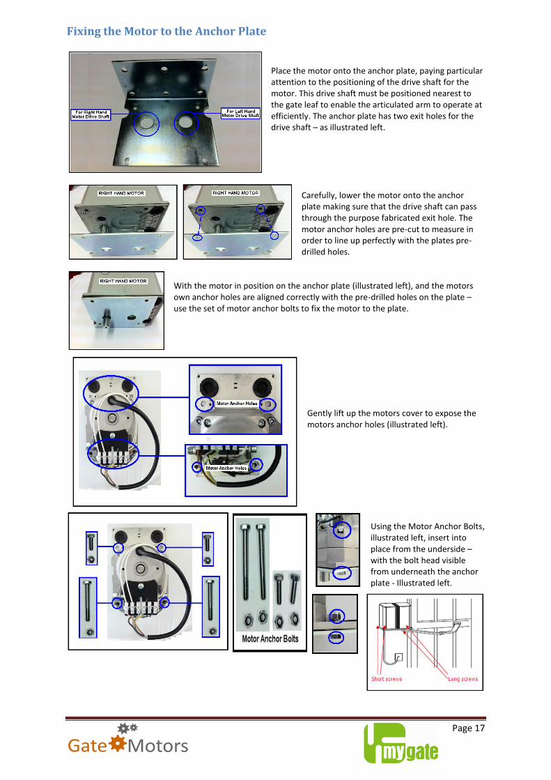
Fixing the Motor to the Anchor Plate Place the motor onto the anchor plate, paying particular attention to the positioning of the drive shaft for the motor. This drive shaft must be positioned nearest to the gate leaf to enable the articulated arm to operate at efficiently. The anchor plate has two exit holes for the drive shaft – as illustrated left.
Carefully, lower the motor onto the anchor plate making sure that the drive shaft can pass through the purpose fabricated exit hole. The motor anchor holes are pre-cut to measure in order to line up perfectly with the plates pre-drilled holes.
With the motor in position on the anchor plate (illustrated left), and the motors own anchor holes are aligned correctly with the pre-drilled holes on the plate – use the set of motor anchor bolts to fix the motor to the plate.
Gently lift up the motors cover to expose the motors anchor holes (illustrated left).
Using the Motor Anchor Bolts, illustrated left, insert into place from the underside – with the bolt head visible from underneath the anchor plate - Illustrated left.
Page 18
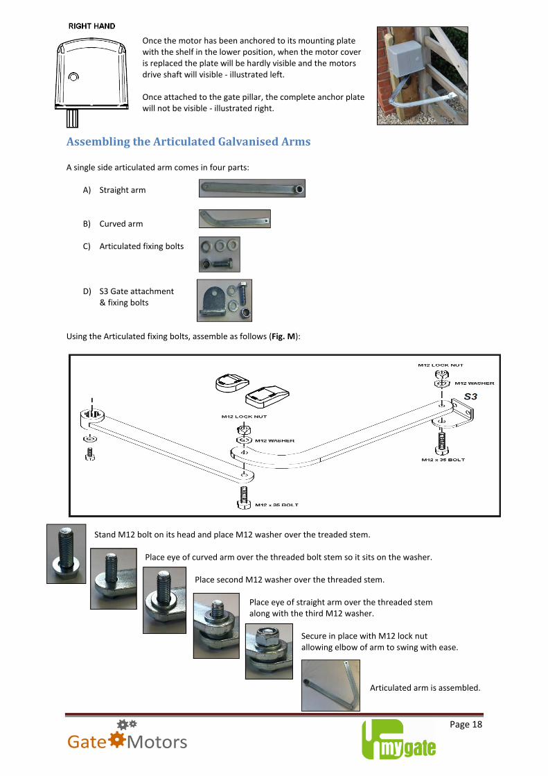
Once the motor has been anchored to its mounting plate with the shelf in the lower position, when the motor cover is replaced the plate will be hardly visible and the motors drive shaft will visible - illustrated left. Once attached to the gate pillar, the complete anchor plate will not be visible - illustrated right.
Assembling the Articulated Galvanised Arms A single side articulated arm comes in four parts:
A) Straight arm
B) Curved arm
C) Articulated fixing bolts
D) S3 Gate attachment & fixing bolts
Using the Articulated fixing bolts, assemble as follows (Fig. M):
Stand M12 bolt on its head and place M12 washer over the treaded stem.
Place eye of curved arm over the threaded bolt stem so it sits on the washer.
Place second M12 washer over the threaded stem.
Place eye of straight arm over the threaded stem
along with the third M12 washer.
Secure in place with M12 lock nut allowing elbow of arm to swing with ease.
Articulated arm is assembled.
Page 19
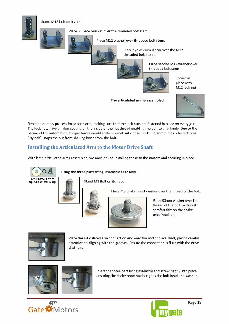
Stand M12 bolt on its head.
Place S3 Gate bracket over the threaded bolt stem.
Place M12 washer over threaded bolt stem.
Place eye of curved arm over the M12
threaded bolt stem. Place second M12 washer over threaded bolt stem
Secure in place with M12 lock nut.
The articulated arm is assembled
Repeat assembly process for second arm, making sure that the lock nuts are fastened in place on every join. The lock nuts have a nylon coating on the inside of the nut thread enabling the bolt to grip firmly. Due to the nature of the automation, torque forces would shake normal nuts loose. Lock nut, sometimes referred to as “Nylock”, stops the nut from shaking loose from the bolt.
Installing the Articulated Arm to the Motor Drive Shaft With both articulated arms assembled, we now look to installing these to the motors and securing in place.
Using the three parts fixing, assemble as follows:
Stand M8 Bolt on its head.
Place M8 Shake proof washer over the thread of the bolt.
Place 30mm washer over the thread of the bolt so its rests comfortably on the shake proof washer.
Place the articulated arm connection end over the motor drive shaft, paying careful attention to aligning with the grooves. Ensure the connection is flush with the drive shaft end.
lnsert the three part fixing assembly and screw tightly into place ensuring the shake proof washer grips the bolt head and washer.
Page 20
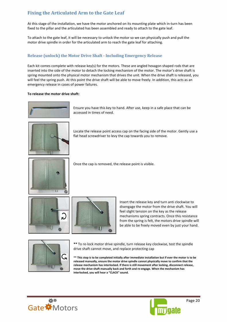
Fixing the Articulated Arm to the Gate Leaf At this stage of the installation, we have the motor anchored on its mounting plate which in-turn has been fixed to the pillar and the articulated has been assembled and ready to attach to the gate leaf. To attach to the gate leaf, it will be necessary to unlock the motor so we can physically push and pull the motor drive spindle in order for the articulated arm to reach the gate leaf for attaching.
Release (unlock) the Motor Drive Shaft - Including Emergency Release
Each kit comes complete with release key(s) for the motors. These are angled hexagon shaped rods that are inserted into the side of the motor to detach the locking mechanism of the motor. The motor’s drive shaft is spring mounted onto the physical motor mechanism that drives the unit. When the drive shaft is released, you will feel the spring push. At this point the drive shaft will be able to move freely. In addition, this acts as an emergency release in cases of power failures. To release the motor drive shaft:
Ensure you have this key to hand. After use, keep in a safe place that can be accessed in times of need. Locate the release point access cap on the facing side of the motor. Gently use a flat head screwdriver to levy the cap towards you to remove. Once the cap is removed, the release point is visible.
Insert the release key and turn anti clockwise to disengage the motor from the drive shaft. You will feel slight tension on the key as the release mechanisms spring contracts. Once this resistance from the spring is felt, the motors drive spindle will be able to be freely moved even by just your hand.
** To re-lock motor drive spindle, turn release key clockwise, test the spindle drive shaft cannot move, and replace protecting cap ** This step is to be completed initially after immediate installation but if ever the motor is to be released manually, ensure the motor drive spindle cannot physically move to confirm that the release mechanism has interlocked. If there is still movement after locking, disconnect release, move the drive shaft manually back and forth and re-engage. When the mechanism has interlocked, you will hear a “CLACK” sound.
Page 21
Attaching Articulated Arm to the Gate Leaf
With the motor’s drive spindle in free position and with the articulated arm attached to the spindle, we can now fix the S3 bracket to the gate. With the gates in a closed position, push the articulated arm round to the gate leaf, taking into account the measurements and positioning on the gate calculated earlier in the installation (refer to pages 14-15) ensuring that the articulated arm’s elbow join forms an angle, illustrated below:
Depending on the type of gate material (metal / wooden) use suitable M8 bolts / screws to ensure bracket is fastened tightly. It may be necessary to bolt through the gate to ensure fixings do not come loose through torque force vibration and to avoid splintering / cracking around fixing entry point. With the motor drive shaft still unlocked, move the gate manually back and forth to test your alignment of the articulated arm compared to the gate and if the gate can swing with no hinge grinding / jolting movement. Pay attention to how the articulated arm folds in as the gate opens and ensure there are no obstruction to the flow of the articulation. This is a simulation of how the automation will operate. Next stage is to set the CAM switches to regulate the open / close cycles.
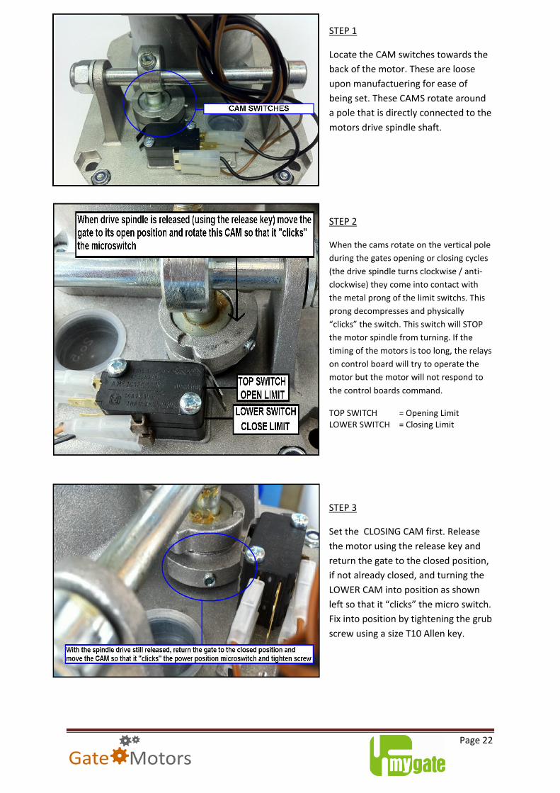
Setting the limit switches for the gate leaf’s open and closed position Each motor is supplied with built-in limit stops. These are physical switches that literally turn off the motors to prevent them from moving the gate any further than designated. It is an electrical gate stop and preserves the long lasting life of the motor’s components. Compared to the linear range of motors, the Kit MyHook is designed in a very different way therefore the limit switches are to be used. Physical gate stops are required to present the form of resistance the motors needed in accompany the installation to regulate the duty cycles to ensure continued smooth operation. The limit switches are connected directly to the power source that feeds the motors – Please keep your fingers clear of the switches at all times when power is connected to the control board and especially in operation as there is a high risk of potential shock and finger entrapment. Follow the next step of instructions to set the CAM switches.
Page 22
STEP 1
Locate the CAM switches towards the
back of the motor. These are loose
upon manufactuering for ease of
being set. These CAMS rotate around
a pole that is directly connected to the
motors drive spindle shaft.
STEP 2
When the cams rotate on the vertical pole
during the gates opening or closing cycles
(the drive spindle turns clockwise / anti-
clockwise) they come into contact with
the metal prong of the limit switchs. This
prong decompresses and physically
“clicks” the switch. This switch will STOP
the motor spindle from turning. If the
timing of the motors is too long, the relays
on control board will try to operate the
motor but the motor will not respond to
the control boards command.
TOP SWITCH = Opening Limit LOWER SWITCH = Closing Limit
STEP 3
Set the CLOSING CAM first. Release
the motor using the release key and
return the gate to the closed position,
if not already closed, and turning the
LOWER CAM into position as shown
left so that it “clicks” the micro switch.
Fix into position by tightening the grub
screw using a size T10 Allen key.
Page 23
STEP 4
With the drive shaft still released,
move the gate to the open position.
Once in the correct position, rotate
the TOP CAM clockwise so it
“clicks”the microswicth. Tighten with
size T10 Allen Key. The OPENING CAM
should be in a fixed position and must
not move. The motor’s are powerful
and the CAM will move if not
anchored correctly with the Allen key
grub screw.
LEFT HAND MOTOR
Open CAM rotates clockwise
Closing CAM rotates anti-clockwise
RIGHT HAND MOTOR
Open CAM rotates anti-clockwise
Closing CAM rotates clockwise
Please remember that as much as the switches regulate the cycles by physically turning off the
motor to stop it moving further, Gate Stops must still be used to provide adequate resistance for the
motors to detect which will avoid over-running of the spindle drive and will prevent the CAMS
getting stuck/wedged on the metal prongs of the micro switch.
The CAM switches can be re-positioned at any time if the need for a shorter / wider opening angle
arises. Simply follow the steps 1 to 4 and re-perform the Programming as described in the Q71B
Control Board for Swing Gates Instruction guide to enable the control board to adjust its motor
running time parameters to suit.
Although the operation of the motors is governed by the control board, it is advised to use the micro switches in conjunction for continued efficient automation of the gates.
Page 24
Re-lock the motor using the release key supplied to ensure the gate cannot move when manual force is applied. This ensures the spring mounted release mechanism has interlocked with the motor gears. If the motor is not re-locked, when the automation is activated the motor spindle will just spin with no movement produced by the articulated arm.
Connecting Motor Wiring to the Q71B Control Board
With the motor’s now in position, CAM limit switches set and the motors locked, we now look to connecting the wiring connections to the Q71B Double Swing Gate Control Board. Contained within the left hand motor housing, fixed to the rear of the motor is the control board (illustrated below). From production, by default, the LEFT HAND motor is always pre-wired and connected to the control board.
Page 25
Connecting Right Hand Motor
Connecting to the right hand motor to the control board will
require the use of 1.5mm 4 core armoured cable. 4 core cable flex
could be used but it is strongly recommended to use armoured
cable for safety as often cables need to be laid under the
driveway to connect the right hand motor.
Your connections on the motor should be as illustrated left.
Using the clear cable ties supplied within the bracket pack, anchor
your cable to the base of the motor. Pierce and gently feed the
cable though the rubber grommets, illustrated below.
Connect to the control board following the wiring to terminal arrangement as per your need for the
installation (left hand opening first or right hand opening first) as described on pages 26 / 27.
One Gate Leaf to Open Before the Other
From installation to installation all gates are different in size, shape and construction. In cases where there is a small gap between each leaf and/or no gap at all, or where there is a “Lip” on one leaf designed to hold the other together (like a Centre Gate Stop), one leaf of the gate may need to open / close before the other.
The control board features terminal groupings for the motors.
Motor 1 = 4, 5, 6 Motor 2 = 7, 8, 9 The motor which is wired into terminals 7 & 8 & 9 will OPEN first and CLOSE second. This is an operating feature and is designed to cater for gates where an overlay is used on a leaf to keep the gates together.
Page 26
Inward and Outward Opening The Kit MyHook is versatile in which direction it can travel so it can open inwards and outwards. The following few pages show wiring diagrams to explain how the motors are connected to the Q71B Control Board depending on how they are to operate depending on whether the gates are to open inwards or outwards. Inward Opening Double Leaf Gate For gates that open inwards, The Kit Simply can operate a specific handed gate leaf before the other. This comes into play where there is a “lip” on a gate leaf which keeps the gates together or there are specific requirements to have one leaf open before the other. Please follow the wiring diagram below for the connection to the Q71B Swing Gate Control Board if:
First leaf to open is the left hand side:
First leaf to open is the right hand side:
Outward Opening Double Leaf Gate The motor wiring is specific to gates opening inwards (most common), however for gates that open outwards, simply swap the BROWN & BLACK wire connections to the control board:
First leaf to open is the left hand side:
First leaf to open is the right hand side:
Page 27
Installation Complete Now your installation is complete with the fixing of the motors to the gate, please proceed to installing the safety devices and other equipment supplied or purchased with your kit to the control board. Please carefully follow the Q71B Control Board instruction guide that accompanies the kit to ensure smooth operation of your gate automation.
Warranty The 12 months Limited Warranty on all goods supplied by GateMotors is on a return for repair basis. Any longer warranty issued by a manufacturer will require these to be returned to the manufacturer’s head office or service address, in or outside the United Kingdom. GateMotors shall not be liable in any way for failure of any product supplied. In particular GateMotors shall not be liable for labour costs involved in replacing faulty items or fault finding. GateMotors warrants to you that the supplied goods will be free from defects in workmanship and materials under normal use for a period of one (1) year from the date that the goods were first purchased by you. If a defect arises and a valid claim under this Limited Warranty is received by GateMotors after the first one hundred and eighty (180) days of the warranty period, GateMotors is entitled to charge you for any reasonable shipping and handling costs made in connection with the repair or replacement of the goods. You must comply with any other return procedures stipulated by GateMotors, if any. What this warranty does not cover - The Limited Warranty does not apply when the goods have been opened or repaired by someone not authorised by GateMotors and does not cover repair or replacement of any goods or part thereof damaged by: misuse, moisture, liquids, proximity or exposure to heat and accident, abuse, non-compliance with the installation and/or usage instructions supplied with the goods, neglect or misapplication. Any disfigurement / removal / tampering of any labels attached to the product, will invalidate the warranty. The Limited Warranty does not cover physical damage to the surface of the product or calibration of the product. This Limited Warranty cannot be transferred to any other person. This Limited Warranty does not affect any legal rights under applicable national legislation governing the sale of consumer goods.
Obtaining Repairs & Replacements (In warranty & out of warranty) Goods should not be returned for repair or warranty claim without first obtaining a Returns Authorisation Number (RAN) failure to obtain a RAN will result in the returned goods being turned away from our Goods-In and returned to the invoice address as undeliverable. In addition, goods returned for repair or warranty claim must be accompanied by a note indicating the nature of the suspected defect, showing clearly the returnee's full name and address and giving proof of purchase from GateMotors. All goods returned to us for repair or warranty claim will be inspected and repaired / replaced as necessary. In warranty repairs will not carry any parts or labour charges, provided the products were found to be faulty due to component failure. Out of warranty repairs will be subject to charges which cover the labour, replacement components and carriage. We will excise a Lien as described above, where payment for goods or services has not been made. Where we deem a repair to be uneconomical, we will contact you for a decision on our course of action.
Page 28
Kit MyHook 230v – FAQ’s
Will my gates still open in the winter when it is very cold and icy?
Climate conditions do affect how the internal mechanics operate. During periods where the outside temperature can drop as low as -20 in some parts of the UK, the motors can physically have trouble starting, just like a motor vehicle. Although the internal gears are protected by machine grease, of course anti-freeze cannot be used. If the motors do struggle to push and pull the gates and you are finding them closing short or opening short, a simple adjustment to the torque force is required to give the motors an extra helping hand. This adjustment will increase the power output to the motor to help it mobilise. During the summer season or where the temperature increases, this torque force adjustment may need to be reversed as the mechanics will be able to move a lot more freely and you may find your gates closing quicker or over closing / opening. If you are finding ice forming on the motor arms, wiping the arm with liquid paraffin will help reduce ice formation. Due to the unique way the motors are fabricated, no ice will get into the motor via the arms, however if it has settled and compacts when the arm retracts to open your gate, the ice build-up may force the arm not to fully retract.
How can I be sure that the gates are securely closed to keep unwelcome visitors out and
my children and dogs in?
Each GateMotors control has the option of operating the motors in one of two ways:
- Full Automatic mode where a press of the transmitter button will open the gate and hold it open for a predetermined time (adjustable to between 5 & 90 seconds) and then close it automatically. This way no one needs to remember to shut the gate.
- Semi Automatic mode where one press of the button will open the gate as before, but it won't close automatically until the button is pressed again.
What if I am delayed and the gates start to close before I am through the entrance?
Included in each GateMotors kit is a pair of safety photocells that are normally mounted on each gatepost and project a beam across the entrance. If your car or any object (e.g. child or pet) breaks this beam the gate will either not move, or if it has already started to close, stop moving then reverse open again. If you have large / deep gates then an additional pair of photocells should be purchased and mounted on posts just beyond the leading edges of the open gate (see accessories); these will protect the full radial sweep of the gate.
Do my motors require maintenance?
GateMotors electromechanical motors do require minimum maintenance to ensure safe operation. The internal gears and mechanisms to control the ram arm motion are protected by internal Machine Grease and do not require a re-fill. Ensure that the control boards associated safety devices (photocells / anti-crush barriers) are kept free from grime and obvious obstructions including fallen branches et cetera, and do grease the pivot points regularly on the motors and your gate hinges. It is recommended to have the gate automation serviced by professional gate installers / gate maintenance specialists to ensure your automation is working safely and efficiently. Installers / Maintenance teams can be found in local directories and internet search engines.
Page 29
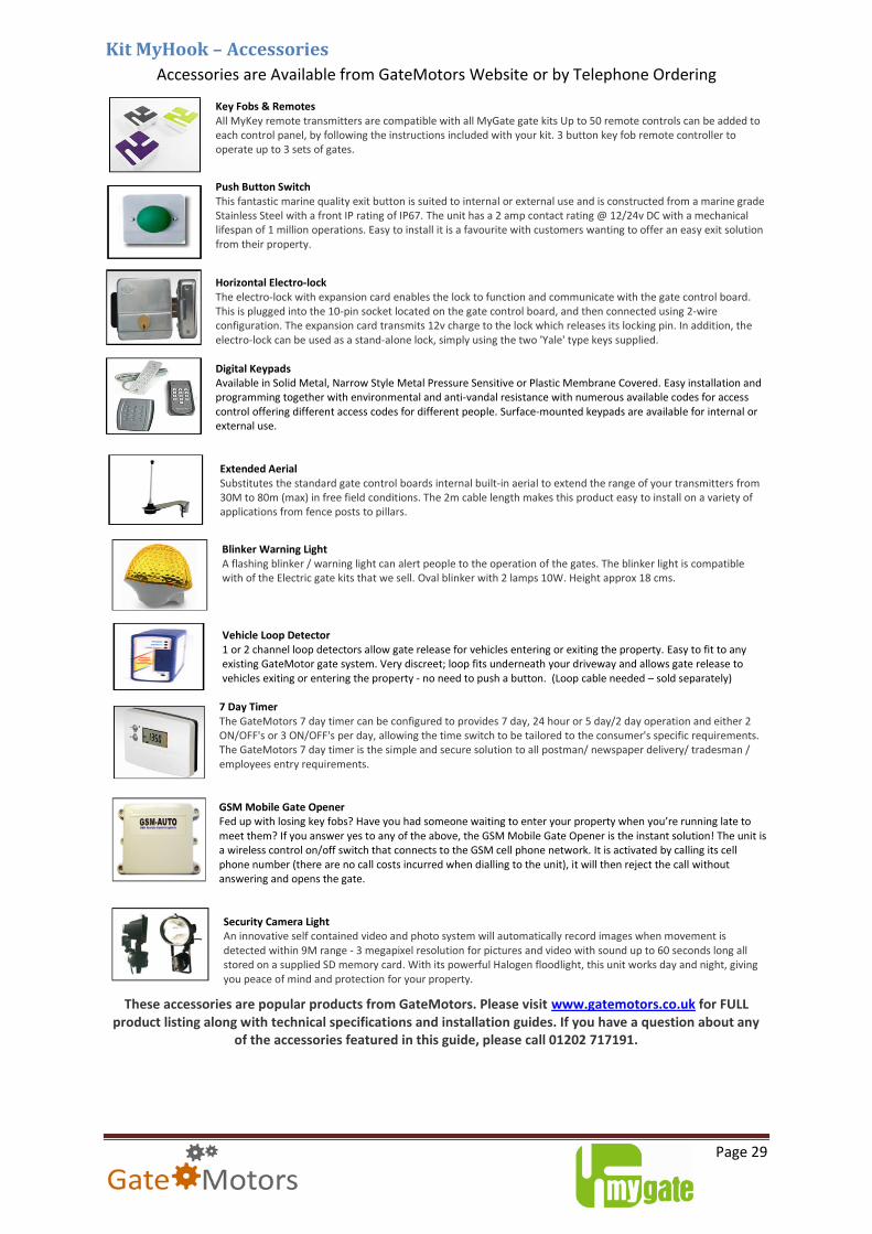
Kit MyHook – Accessories
Accessories are Available from GateMotors Website or by Telephone Ordering Key Fobs & Remotes All MyKey remote transmitters are compatible with all MyGate gate kits Up to 50 remote controls can be added to each control panel, by following the instructions included with your kit. 3 button key fob remote controller to operate up to 3 sets of gates.
Push Button Switch This fantastic marine quality exit button is suited to internal or external use and is constructed from a marine grade Stainless Steel with a front IP rating of IP67. The unit has a 2 amp contact rating @ 12/24v DC with a mechanical lifespan of 1 million operations. Easy to install it is a favourite with customers wanting to offer an easy exit solution from their property.
Horizontal Electro-lock The electro-lock with expansion card enables the lock to function and communicate with the gate control board. This is plugged into the 10-pin socket located on the gate control board, and then connected using 2-wire configuration. The expansion card transmits 12v charge to the lock which releases its locking pin. In addition, the electro-lock can be used as a stand-alone lock, simply using the two 'Yale' type keys supplied. Digital Keypads Available in Solid Metal, Narrow Style Metal Pressure Sensitive or Plastic Membrane Covered. Easy installation and programming together with environmental and anti-vandal resistance with numerous available codes for access control offering different access codes for different people. Surface-mounted keypads are available for internal or external use. Extended Aerial Substitutes the standard gate control boards internal built-in aerial to extend the range of your transmitters from 30M to 80m (max) in free field conditions. The 2m cable length makes this product easy to install on a variety of applications from fence posts to pillars.
Blinker Warning Light A flashing blinker / warning light can alert people to the operation of the gates. The blinker light is compatible with of the Electric gate kits that we sell. Oval blinker with 2 lamps 10W. Height approx 18 cms. Vehicle Loop Detector 1 or 2 channel loop detectors allow gate release for vehicles entering or exiting the property. Easy to fit to any existing GateMotor gate system. Very discreet; loop fits underneath your driveway and allows gate release to vehicles exiting or entering the property - no need to push a button. (Loop cable needed – sold separately)
7 Day Timer The GateMotors 7 day timer can be configured to provides 7 day, 24 hour or 5 day/2 day operation and either 2 ON/OFF's or 3 ON/OFF's per day, allowing the time switch to be tailored to the consumer's specific requirements. The GateMotors 7 day timer is the simple and secure solution to all postman/ newspaper delivery/ tradesman / employees entry requirements. GSM Mobile Gate Opener Fed up with losing key fobs? Have you had someone waiting to enter your property when you’re running late to meet them? If you answer yes to any of the above, the GSM Mobile Gate Opener is the instant solution! The unit is a wireless control on/off switch that connects to the GSM cell phone network. It is activated by calling its cell phone number (there are no call costs incurred when dialling to the unit), it will then reject the call without answering and opens the gate.
Security Camera Light An innovative self contained video and photo system will automatically record images when movement is detected within 9M range - 3 megapixel resolution for pictures and video with sound up to 60 seconds long all stored on a supplied SD memory card. With its powerful Halogen floodlight, this unit works day and night, giving you peace of mind and protection for your property.
These accessories are popular products from GateMotors. Please visit www.gatemotors.co.uk for FULL product listing along with technical specifications and installation guides. If you have a question about any
of the accessories featured in this guide, please call 01202 717191.
Comments & Feedback We thank you for taking the time in reading and following the new version of our instructions. This instruction guide has been compiled from comments and feedbacks received from previous / existing customers who are familiar with our automation and had followed the old version (also included alongside with this guide). The aim of this guide is to appeal to all “walks” of life - from end users to Tradesmen. We understand that not everyone can follow complex wiring diagrams and often instructions can be over complicated. We, at Gate Motors, feel that a “one size fits all” guide, with simple straight forward jargon-free would benefit the customer & installers alike and promote safe operation of the automation. Your feedback is valuable to us to help us with continued development and fine tuning of our instructions to suit customers’ needs. If there is a subject or topic relating to the control board and its functions that you feel we could include, re-write or present in a different way, please let us know by email on: [email protected]. Published: - December 2012 ver 1 Author: - G.Opie
For more information on GateMotors full line of automatic gate openers and access controls visit our website at www.gatemotors.co.uk
Phone Technical Lines UK: 0911 6038046 * (service available 8:30am to 5:30pm Monday to Friday only, closed Weekends and Public Holidays) ROI: 156 099 9667** (service available 8:30am to 5:30pm Monday to Friday only, closed Weekends and Public Holidays) Email: [email protected] *UK calls to this number are billed by the second and cost £1.02 per minute from a standard landline; other networks charges may also apply. **IRISH calls to this number are billed by the second and cost €1.25 per minute from a standard landline; other networks charges may also apply. Service is provided by Digital Select Ltd, 271 Regent Street, London, W1B 2ES whose helpline number is 0844 448 0165
Trading address: GateMotors UK, Unit 16c, Chalwyn Industrial Estate, St. Clements Road, Poole, Dorset. BH12 4PE. GateMotors is the trading name of Screwjack Limited - registered office at 21 Oxford Road, Bournemouth, Dorset. BH8 8ET. Registered # is 4287804, VAT #:785 3450 06