75
1 Installation manual IBC TopFix 200 Version 15.02, as of: 07/21/2015
1
Installation manual
IBC TopFix 200 Version 15.02, as of: 07/21/2015

2
Version 15.02, as of: 07/21/2015
Dear customer,
Congratulations, you have chosen an IBC product! Experience for yourself the quality and reliability of the IBC TopFix 200 module mounting system.
To simplify the installation and commissioning of your IBC TopFix 200 mounting system, we have included these detailed installation instructions. They are intended to help you to become familiar with how to fit the
frame and the modules quickly.
Please read these instructions carefully before starting the installation. In case of any questions, please
get in touch with your IBC SOLAR contact who will be pleased to help.
Sunny greetings
Your IBC SOLAR AG team
3
Version 15.02, as of: 07/21/2015
Contents
01. What you will need: tool list .............................................................................................................. 4
02. General information, standards and regulations .............................................................................. 5
03. Mounting diagram ............................................................................................................................ 9
04. Fitting the various mounting systems ............................................................................................. 13
05. Fitting carrier rails .......................................................................................................................... 47
06. Fitting PV modules ......................................................................................................................... 49
07. Fitting cable clips ........................................................................................................................... 51
08. Fitting the two-layer carrier system ................................................................................................ 52
09. Delta support ................................................................................................................................. 54
10. IBC FrameFix module frame reinforcements ................................................................................. 59
11. Bill of materials .............................................................................................................................. 60
12. Appendix ........................................................................................................................................ 71
4
Version 15.02, as of: 07/21/2015
01. What you will need: tool list
� Cordless screwdriver with a variety of bits (Torx, Phillips, etc.)
� Drill bits (up to Ø 15 mm)
� Pencil
� Tape measure
� Folding rule
� Plumb line
� Open-ended spanner
� Power drill or cordless screwdriver with wrench socket and torque control
� Angle grinder with diamond cutting disc
� Torx screwdriver with T-grip, size TX40, TX25
� Torque wrench
Section “Required tools/auxiliary agents” lists any additional tools required exclusively for our IBC
trapezoidal sheet metal assembly system as the mounting system fastener type differs from some other
fasteners. For this reason, we have described these in a separate section.
5
Version 15.02, as of: 07/21/2015
02. General information, standards and regulations
The IBC TopFix 200 mounting system is used for installing your solar modules. The modules are fastened
by means of clamps and carrier rails.
The number of components varies according to the size of the system.
Important information: � Your IBC TopFix 200 mounting system is supplied completely with all accessories.
� Before you begin, please check that all parts are included using the packing list and bill of materials.
� Electrical work must be carried out by qualified electricians only!
� Comply with the processing guidelines and – in individual cases – specific guidelines from the relevant
roofing and module manufacturers.
� Condition for the 10-year guarantee to be granted: this applies with the use of IBC SOLAR AG
components only. No guarantee claims can be accepted if third-party components are used.
General important information and standards relatin g to dimensioning The entire photovoltaic (PV) system must be installed in accordance with the generally recognised
engineering standards. Comply with accident prevention regulations of the German employer's liability insurance associations (Berufsgenossenschaften), in particular:
� BGV A1 General instructions
� BGV A2 Electrical systems and equipment
� BGV C22 Construction work
� BGV D36 Ladders and steps
Please ensure that installation work takes account of the actual conditions at the installation site and is in accordance with the generally recognised engineering standards. Local regulations must be complied with.
Please observe all regulations and guidelines under public law during planning, erection, operation and maintenance of PV plants connected to grids including the following: EN standards, DIN standards, TAB,
accident prevention regulations, the guidelines from the association of property insurers (VDS – fire
protection guidelines), the trade guidelines of the German roofing association (Fachregeln des Deutschen
Dachdeckerhandwerks) and general guidelines (e.g. timber structures, roofing and roof-sealing works).
6
Version 15.02, as of: 07/21/2015
Please note in particular (this is not an exhaustive list):
� DIN/VDE 0100, particularly part 712 (erection of power installations with nominal voltage up to 1000V)
� DIN/VDE 0298 (electrical wiring)
� VDI 6012 (distributed energy systems in buildings – photovoltaic)
� DIN/VDE 0126 (solar energy systems for domestic use)
� DIN/VDE 0185 parts 1 to 4 (lightning protection)
� DIN 18338 Roof covering and roof sealing works
� DIN 18451 Scaffolding works
� DIN 18015 Planning and erection of electrical installations in residential buildings
� TAB (utility companies' technical low-voltage grid connection conditions)
� VDEW standard (standards for the connection and parallel operation of independent generation
systems on low-voltage grids)
� Information on manufacture, planning and implementation of solar plants from the German Institute of
Civil Engineering (DIBt), in the current edition
� DIBt building regulation list, in the current edition
� DIN 4102-1:1998 Fire behaviour of building materials and elements – part 1: building materials; classification, requirements and tests
� DIN EN 13501-1:2010-01 Fire classification of construction products and building elements – part 1:
classification using the results from fire behaviour tests on construction products
� EN 1991-1-3 (General actions – snow loads)
� EN 1991-1-4 (General actions – wind loads)
� EN 1993-1-1 Design of steel structures: general rules and rules for buildings
� EN 1995-1-1 Design of timber structures
� EN 1999-1-1 Design of aluminium structures
� General certificate of building approval Z-30.3-6: products, connecting devices and structural
components made from stainless steel
� General building authority approval for individual system components
7
Version 15.02, as of: 07/21/2015
Solar modules Solar modules may only be used if they hold the following valid certification:
� IEC 61215/IEC 61646 and protection class II/IEC 61730
Framed solar modules Please note that the guarantee for the solar modules will be rendered void if modifications are made to the
module frames (e.g. by drilling additional holes). In order to comply with warranty conditions, the
installation instructions of the respective solar module manufacturer must be strictly observed.
Lightning and overvoltage protection The lightning and overvoltage protection of the PV system must comply with the current specifications of
� DIN/VDE 0185 parts 1 to 4
� DIN/VDE 0100 part 712
� VdS 2010.
Please refer to the specified directives and standards for detailed information. We generally recommend
integrating the mounting system and the module frame into the on-site equipotential bonding and using overvoltage protective equipment.
Equipotential bonding is always required if the solar modules used do not comply with protection class II
and/or transformerless inverters are used.
The cross-section of the equipotential bonding conductor must correspond to the cross-section of the DC main cable; however, it must be at least 6mm² (copper).
If the building is equipped with a lightning protection system and the PV generator is not located within the protective area of the interception device, the module frame and the mounting system must be integrated
into the external lightning protection system and additional overvoltage protective equipment must be
installed.
The electrically conducting connection must have a minimum core size of 16mm² (copper). Please obtain information on the currently applicable, technological standards!
8
Version 15.02, as of: 07/21/2015
Laying the cables Starting with the frame installation, several points concerning the direction of power lines and laying of cables should be observed.
� To avoid overvoltage couplings from lightning strikes, the resulting conductor loop must be kept to a minimum.
� Routed cables must not obstruct any potential snow and ice from sliding down.
� Water must not collect around routed cables, ensure continuous water drainage.
� Route cables with maximum possible UV and weather protection.
Dimensioning Our TopFix 200 mounting system is dimensioned using our very own PV Manager software, used to determine the degree of utilisation and hence the suitability of the components to be mounted on your roof.
The software is designed as a planning tool. It does not substitute official, static calculations.
If you do not have the PV Manager available for PV plant dimensioning, please contact your responsible
sales representative to determine and dimension the mounting system.
Important! Any calculations for the roof construction as well as any existing superstructures do not form part of the static calculations as part of the PV substructure dimensioning. A structural engineer must inspect and
approve of the increased and rearranged loads caused by the PV plant on site.
9
Version 15.02, as of: 07/21/2015
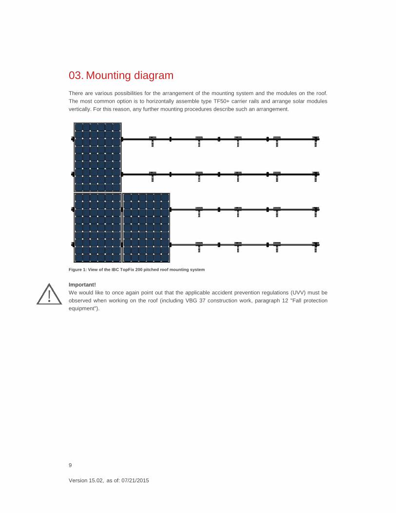
03. Mounting diagram
There are various possibilities for the arrangement of the mounting system and the modules on the roof.
The most common option is to horizontally assemble type TF50+ carrier rails and arrange solar modules
vertically. For this reason, any further mounting procedures describe such an arrangement.
Figure 1: View of the IBC TopFix 200 pitched roof mounting sy stem
Important! We would like to once again point out that the applicable accident prevention regulations (UVV) must be
observed when working on the roof (including VBG 37 construction work, paragraph 12 "Fall protection equipment").
10
Version 15.02, as of: 07/21/2015
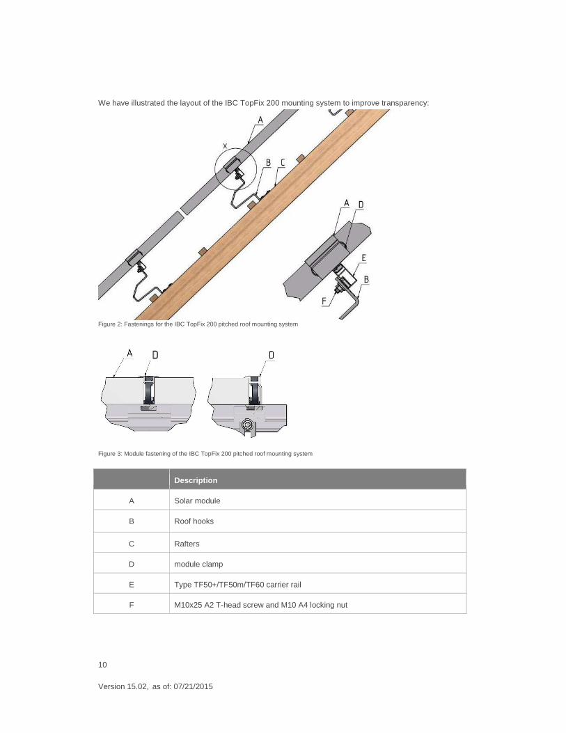
We have illustrated the layout of the IBC TopFix 200 mounting system to improve transparency:
Figure 2: Fastenings for the IBC TopFix 200 pitched roof mounting system
Figure 3: Module fastening of the IBC TopFix 200 pitched roof mounting system
Description
A Solar module
B Roof hooks
C Rafters
D module clamp
E Type TF50+/TF50m/TF60 carrier rail
F M10x25 A2 T-head screw and M10 A4 locking nut
11
Version 15.02, as of: 07/21/2015
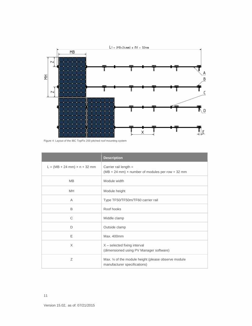
Figure 4: Layout of the IBC TopFix 200 pitched roof mounting system
Description
L = (MB + 24 mm) × n + 32 mm Carrier rail length = (MB + 24 mm) × number of modules per row + 32 mm
MB Module width
MH Module height
A Type TF50/TF50m/TF60 carrier rail
B Roof hooks
C Middle clamp
D Outside clamp
E Max. 400mm
X X – selected fixing interval
(dimensioned using PV Manager software)
Z Max. ¼ of the module height (please observe module
manufacturer specifications)
12
Version 15.02, as of: 07/21/2015
Important! � We would like to point out that the corresponding solar module manufacturers' installation instructions
and specifications must be complied with for warranty reasons.
� Please see the PV Manager for the degree of utilisation and hence the specific suitability of the corresponding mounting components for your roof and take into account on-site conditions as well as
applicable standards and regulations.
� We recommend a clearance of 20 mm between individual modules
13
Version 15.02, as of: 07/21/2015
04. Fitting the various mounting systems
4.1 General dimensioning information
The PV system on your roof is subject to considerable forces caused by snow and, most of all, wind.
Improper fastening of the PV system, particularly the modules, may cause significant damage to objects as
well as personal injury. For this purpose, it is crucial you observe the following section.
The number of fixing points on the roof is always dependent on the particular design of the roof, building height, roof pitch, the wind and snow load zone and a large number of other factors.
Edges and corner areas must be particularly taken into account as per DIN 1055-4 or EN 1991-1-4 (Euro
code 1) as increased loads may apply due to wind dynamics, depending on the building type. For more detailed information, please see the graphical indications of fixing points in our PV Manager software.
Calculate and verify any specific details according to the applicable standards. In this process, we recommend you consult a structural engineer.
Before starting installation, the existing wooden substructure must be checked for sufficient stability. The
wooden substructure must have a service life of more than 20 years. In case of doubt, consult a roofer or joiner and a structural engineer.
As a rule, verify on-site static conditions and whether or not the outer roofing in conjunction with the substructure (steel beams/purlins) is able to bear the additional pressure and dynamic loads of the PV
plant.
We shall not assume any system liability for the integrity of the roof as this mainly depends on the quality of mounting or subsequent sealing procedures. The rules of the building trade as well as guidelines and
instructions of the roofing manufacturer are to be observed. Mounting system parts must not be treated with additional anti-corrosion protection in normal, atmospheric conditions (mainland atmosphere). Take
additional, suitable anti-corrosion protection measures in the event of other assembly locations (e.g.
contact with grit, direct vicinity to the coast, acidic or alkaline environments).
Modifications that are not permitted and improper use of our components during assembly and construction shall render and liability and guarantee claims void.
14
Version 15.02, as of: 07/21/2015
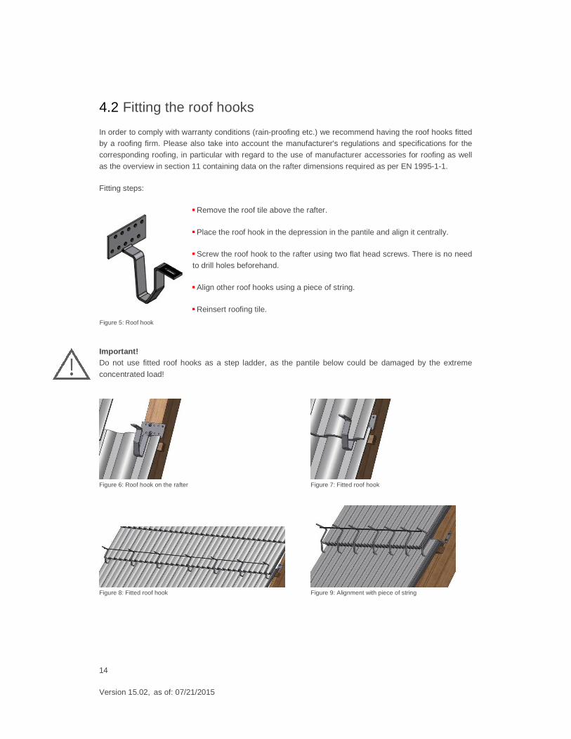
4.2 Fitting the roof hooks
In order to comply with warranty conditions (rain-proofing etc.) we recommend having the roof hooks fitted by a roofing firm. Please also take into account the manufacturer's regulations and specifications for the
corresponding roofing, in particular with regard to the use of manufacturer accessories for roofing as well
as the overview in section 11 containing data on the rafter dimensions required as per EN 1995-1-1.
Fitting steps:
� Remove the roof tile above the rafter.
� Place the roof hook in the depression in the pantile and align it centrally.
� Screw the roof hook to the rafter using two flat head screws. There is no need
to drill holes beforehand.
� Align other roof hooks using a piece of string.
� Reinsert roofing tile.
Important! Do not use fitted roof hooks as a step ladder, as the pantile below could be damaged by the extreme
concentrated load!
Figure 6: Roof hook on the rafter Figure 7: Fitted roof hook
Figure 8: Fitted roof hook Figure 9: Alignment with piece of string
Figure 5: Roof hook
15
Version 15.02, as of: 07/21/2015
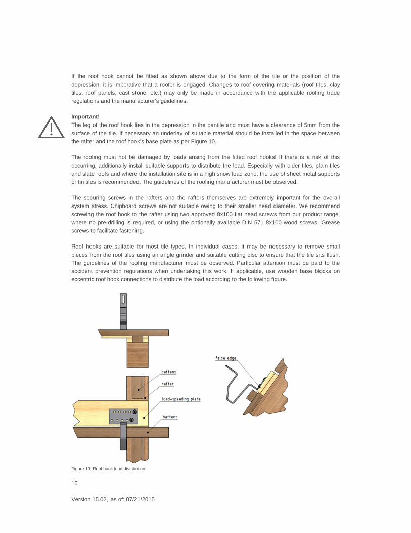
If the roof hook cannot be fitted as shown above due to the form of the tile or the position of the depression, it is imperative that a roofer is engaged. Changes to roof covering materials (roof tiles, clay
tiles, roof panels, cast stone, etc.) may only be made in accordance with the applicable roofing trade
regulations and the manufacturer’s guidelines.
Important! The leg of the roof hook lies in the depression in the pantile and must have a clearance of 5mm from the
surface of the tile. If necessary an underlay of suitable material should be installed in the space between the rafter and the roof hook’s base plate as per Figure 10.
The roofing must not be damaged by loads arising from the fitted roof hooks! If there is a risk of this
occurring, additionally install suitable supports to distribute the load. Especially with older tiles, plain tiles
and slate roofs and where the installation site is in a high snow load zone, the use of sheet metal supports or tin tiles is recommended. The guidelines of the roofing manufacturer must be observed.
The securing screws in the rafters and the rafters themselves are extremely important for the overall system stress. Chipboard screws are not suitable owing to their smaller head diameter. We recommend
screwing the roof hook to the rafter using two approved 8x100 flat head screws from our product range,
where no pre-drilling is required, or using the optionally available DIN 571 8x100 wood screws. Grease
screws to facilitate fastening.
Roof hooks are suitable for most tile types. In individual cases, it may be necessary to remove small
pieces from the roof tiles using an angle grinder and suitable cutting disc to ensure that the tile sits flush. The guidelines of the roofing manufacturer must be observed. Particular attention must be paid to the
accident prevention regulations when undertaking this work. If applicable, use wooden base blocks on
eccentric roof hook connections to distribute the load according to the following figure.
Figure 10: Roof hook load distribution
16
Version 15.02, as of: 07/21/2015
4.3 Roof hook types
Important!
The specifications of the general building approval Z-14.4.-661 for steel roof hooks and Z-14.4.-515 for aluminum roof hooks have to be considered.
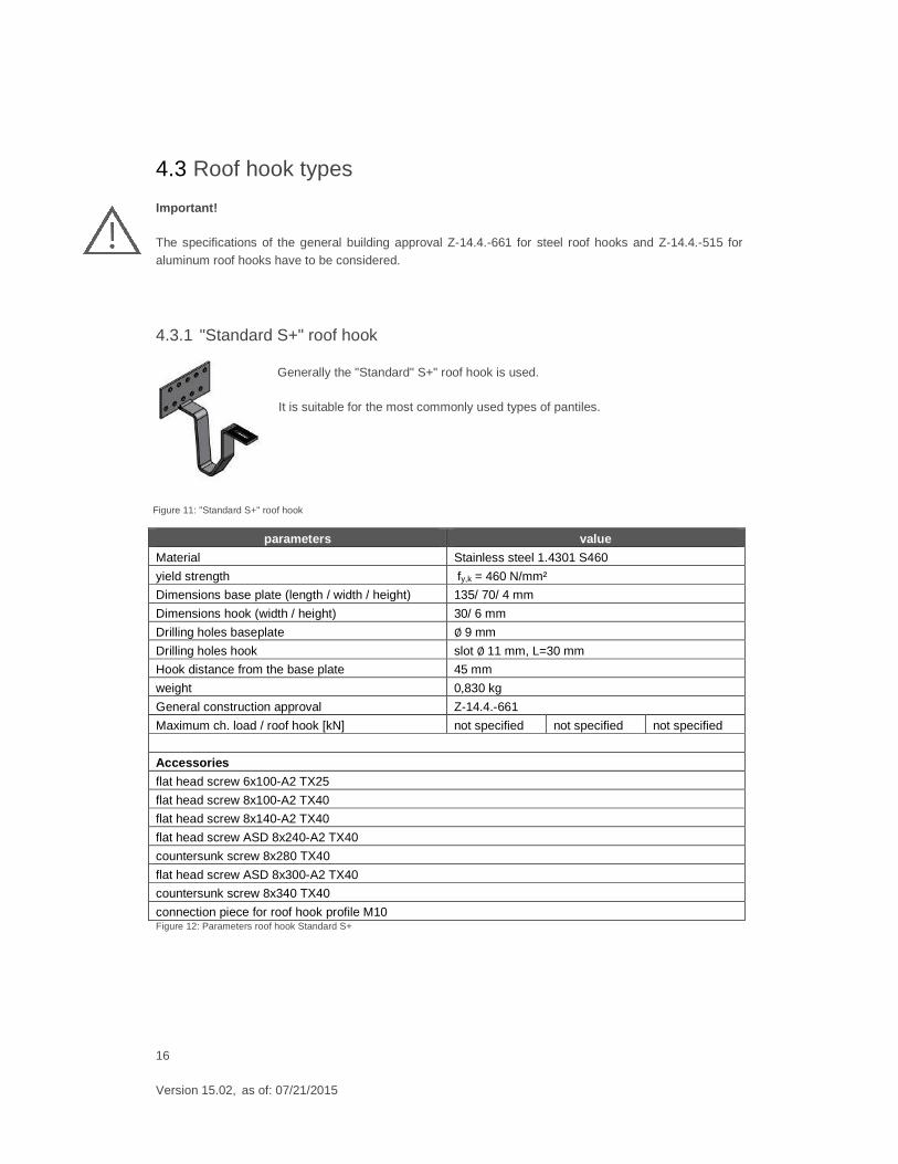
4.3.1 "Standard S+" roof hook Generally the "Standard" S+" roof hook is used.
It is suitable for the most commonly used types of pantiles.
parameters value
Material Stainless steel 1.4301 S460
yield strength fy,k = 460 N/mm²
Dimensions base plate (length / width / height) 135/ 70/ 4 mm
Dimensions hook (width / height) 30/ 6 mm
Drilling holes baseplate ∅ 9 mm
Drilling holes hook slot ∅ 11 mm, L=30 mm
Hook distance from the base plate 45 mm
weight 0,830 kg
General construction approval Z-14.4.-661
Maximum ch. load / roof hook [kN] not specified not specified not specified
Accessories
flat head screw 6x100-A2 TX25
flat head screw 8x100-A2 TX40
flat head screw 8x140-A2 TX40
flat head screw ASD 8x240-A2 TX40
countersunk screw 8x280 TX40
flat head screw ASD 8x300-A2 TX40
countersunk screw 8x340 TX40
connection piece for roof hook profile M10 Figure 12: Parameters roof hook Standard S+
Figure 11: "Standard S+" roof hook
17
Version 15.02, as of: 07/21/2015
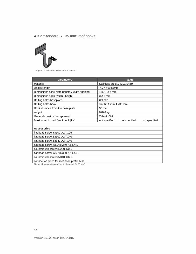
4.3.2 "Standard S+ 35 mm" roof hooks
parameters value
Material Stainless steel 1.4301 S460
yield strength fy,k = 460 N/mm²
Dimensions base plate (length / width / height) 135/ 70/ 4 mm
Dimensions hook (width / height) 30/ 6 mm
Drilling holes baseplate ∅ 9 mm
Drilling holes hook slot ∅ 11 mm, L=30 mm
Hook distance from the base plate 35 mm
weight 0,820 kg
General construction approval Z-14.4.-661
Maximum ch. load / roof hook [kN] not specified not specified not specified
Accessories
flat head screw 6x100-A2 TX25
flat head screw 8x100-A2 TX40
flat head screw 8x140-A2 TX40
flat head screw ASD 8x240-A2 TX40
countersunk screw 8x280 TX40
flat head screw ASD 8x300-A2 TX40
countersunk screw 8x340 TX40
connection piece for roof hook profile M10 Figure 14: parameters roof hook “Standard S+ 35 mm“
Figure 13: roof hook “Standard S+ 35 mm“
18
Version 15.02, as of: 07/21/2015
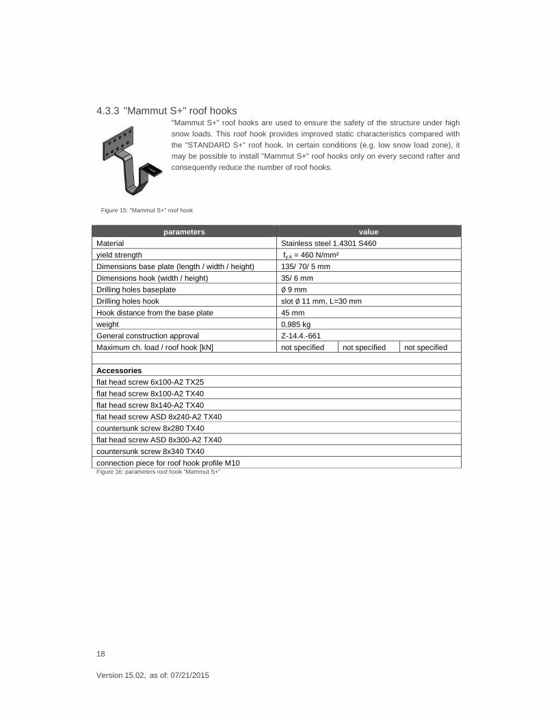
4.3.3 "Mammut S+" roof hooks "Mammut S+" roof hooks are used to ensure the safety of the structure under high
snow loads. This roof hook provides improved static characteristics compared with
the "STANDARD S+" roof hook. In certain conditions (e.g. low snow load zone), it may be possible to install "Mammut S+" roof hooks only on every second rafter and
consequently reduce the number of roof hooks.
parameters value
Material Stainless steel 1.4301 S460
yield strength fy,k = 460 N/mm²
Dimensions base plate (length / width / height) 135/ 70/ 5 mm
Dimensions hook (width / height) 35/ 6 mm
Drilling holes baseplate ∅ 9 mm
Drilling holes hook slot ∅ 11 mm, L=30 mm
Hook distance from the base plate 45 mm
weight 0,985 kg
General construction approval Z-14.4.-661
Maximum ch. load / roof hook [kN] not specified not specified not specified
Accessories
flat head screw 6x100-A2 TX25
flat head screw 8x100-A2 TX40
flat head screw 8x140-A2 TX40
flat head screw ASD 8x240-A2 TX40
countersunk screw 8x280 TX40
flat head screw ASD 8x300-A2 TX40
countersunk screw 8x340 TX40
connection piece for roof hook profile M10 Figure 16: parameters roof hook “Mammut S+”
Figure 15: "Mammut S+" roof hook
19
Version 15.02, as of: 07/21/2015
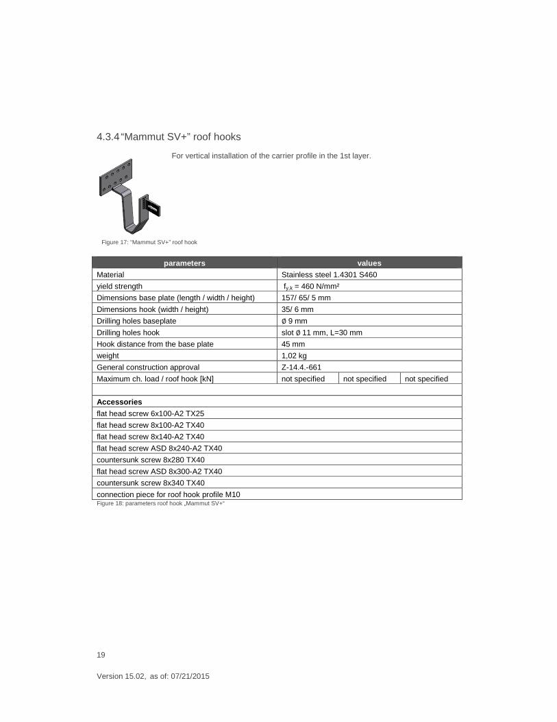
4.3.4 “Mammut SV+” roof hooks
For vertical installation of the carrier profile in the 1st layer.
parameters values
Material Stainless steel 1.4301 S460
yield strength fy,k = 460 N/mm²
Dimensions base plate (length / width / height) 157/ 65/ 5 mm
Dimensions hook (width / height) 35/ 6 mm
Drilling holes baseplate ∅ 9 mm
Drilling holes hook slot ∅ 11 mm, L=30 mm
Hook distance from the base plate 45 mm
weight 1,02 kg
General construction approval Z-14.4.-661
Maximum ch. load / roof hook [kN] not specified not specified not specified
Accessories
flat head screw 6x100-A2 TX25
flat head screw 8x100-A2 TX40
flat head screw 8x140-A2 TX40
flat head screw ASD 8x240-A2 TX40
countersunk screw 8x280 TX40
flat head screw ASD 8x300-A2 TX40
countersunk screw 8x340 TX40
connection piece for roof hook profile M10 Figure 18: parameters roof hook „Mammut SV+“
Figure 17: “Mammut SV+” roof hook
20
Version 15.02, as of: 07/21/2015
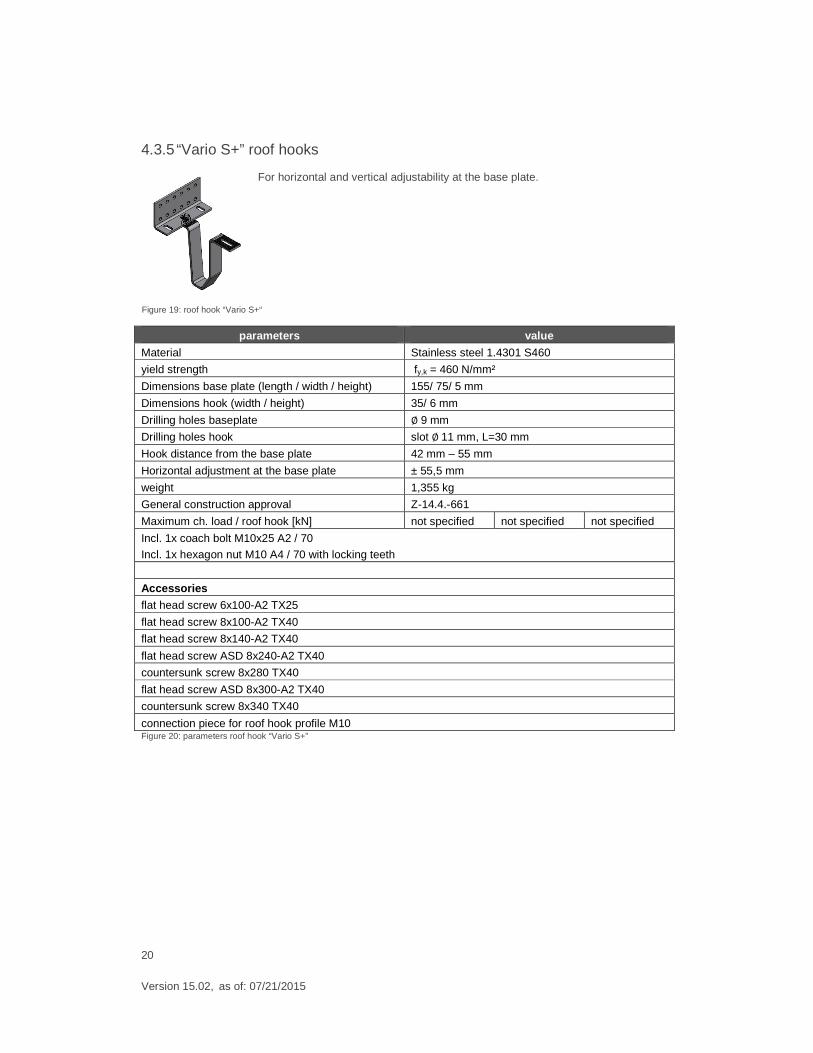
4.3.5 “Vario S+” roof hooks
For horizontal and vertical adjustability at the base plate.
parameters value
Material Stainless steel 1.4301 S460
yield strength fy,k = 460 N/mm²
Dimensions base plate (length / width / height) 155/ 75/ 5 mm
Dimensions hook (width / height) 35/ 6 mm
Drilling holes baseplate ∅ 9 mm
Drilling holes hook slot ∅ 11 mm, L=30 mm
Hook distance from the base plate 42 mm – 55 mm
Horizontal adjustment at the base plate ± 55,5 mm
weight 1,355 kg
General construction approval Z-14.4.-661
Maximum ch. load / roof hook [kN] not specified not specified not specified
Incl. 1x coach bolt M10x25 A2 / 70
Incl. 1x hexagon nut M10 A4 / 70 with locking teeth
Accessories
flat head screw 6x100-A2 TX25
flat head screw 8x100-A2 TX40
flat head screw 8x140-A2 TX40
flat head screw ASD 8x240-A2 TX40
countersunk screw 8x280 TX40
flat head screw ASD 8x300-A2 TX40
countersunk screw 8x340 TX40
connection piece for roof hook profile M10 Figure 20: parameters roof hook “Vario S+”
Figure 19: roof hook “Vario S+“
21
Version 15.02, as of: 07/21/2015
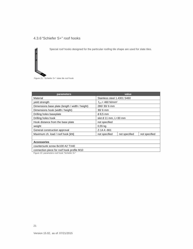
4.3.6 “Schiefer S+” roof hooks
Special roof hooks designed for the particular roofing tile shape are used for slate tiles.
parameters value
Material Stainless steel 1.4301 S460
yield strength fy,k = 460 N/mm²
Dimensions base plate (length / width / height) 280/ 30/ 6 mm
Dimensions hook (width / height) 30/ 6 mm
Drilling holes baseplate ∅ 8,5 mm
Drilling holes hook slot ∅ 11 mm, L=30 mm
Hook distance from the base plate not specified
weight 0,55 kg
General construction approval Z-14.4.-661
Maximum ch. load / roof hook [kN] not specified not specified not specified
Accessories
countersunk screw 8x100 A2 TX40
connection piece for roof hook profile M10 Figure 22: parameters roof hook “Schiefer S+”
Figure 21: "Schiefer S+" slate tile roof hook
22
Version 15.02, as of: 07/21/2015
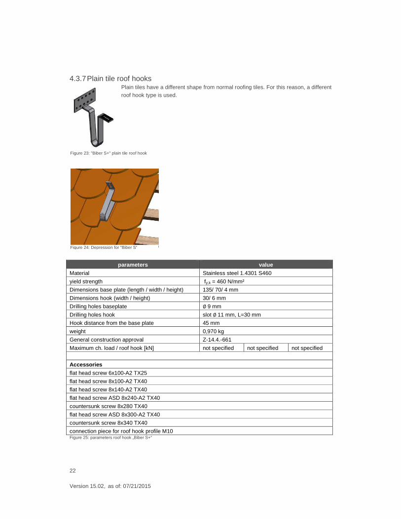
4.3.7 Plain tile roof hooks Plain tiles have a different shape from normal roofing tiles. For this reason, a different roof hook type is used.
parameters value
Material Stainless steel 1.4301 S460
yield strength fy,k = 460 N/mm²
Dimensions base plate (length / width / height) 135/ 70/ 4 mm
Dimensions hook (width / height) 30/ 6 mm
Drilling holes baseplate ∅ 9 mm
Drilling holes hook slot ∅ 11 mm, L=30 mm
Hook distance from the base plate 45 mm
weight 0,970 kg
General construction approval Z-14.4.-661
Maximum ch. load / roof hook [kN] not specified not specified not specified
Accessories
flat head screw 6x100-A2 TX25
flat head screw 8x100-A2 TX40
flat head screw 8x140-A2 TX40
flat head screw ASD 8x240-A2 TX40
countersunk screw 8x280 TX40
flat head screw ASD 8x300-A2 TX40
countersunk screw 8x340 TX40
connection piece for roof hook profile M10 Figure 25: parameters roof hook „Biber S+“
Figure 23: "Biber S+" plain tile roof hook
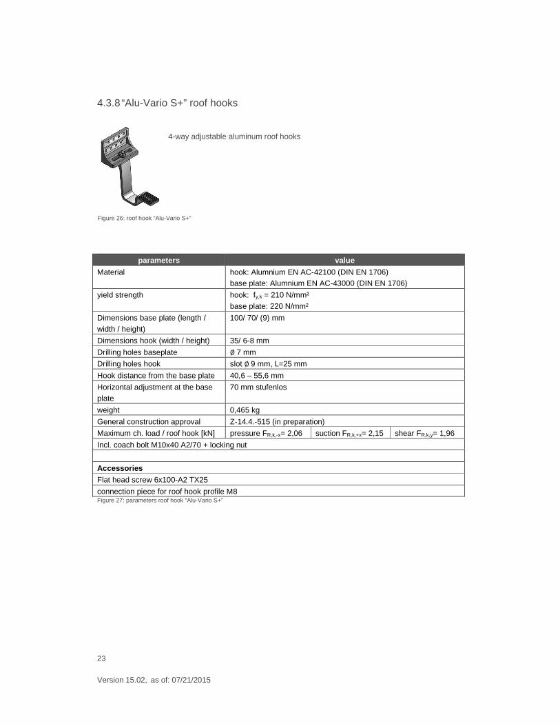
Figure 24: Depression for "Biber S"
23
Version 15.02, as of: 07/21/2015
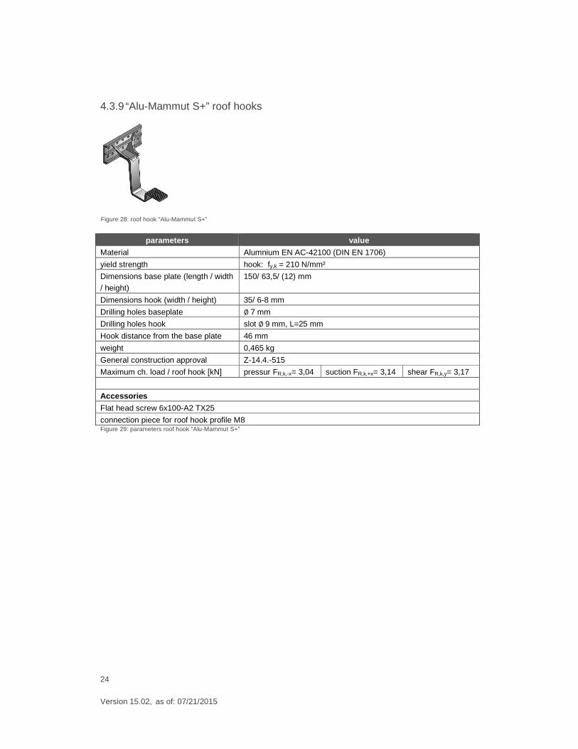
4.3.8 “Alu-Vario S+” roof hooks
4-way adjustable aluminum roof hooks
parameters value
Material hook: Alumnium EN AC-42100 (DIN EN 1706) base plate: Alumnium EN AC-43000 (DIN EN 1706)
yield strength hook: fy,k = 210 N/mm²
base plate: 220 N/mm²
Dimensions base plate (length /
width / height)
100/ 70/ (9) mm
Dimensions hook (width / height) 35/ 6-8 mm
Drilling holes baseplate ∅ 7 mm
Drilling holes hook slot ∅ 9 mm, L=25 mm
Hook distance from the base plate 40,6 – 55,6 mm
Horizontal adjustment at the base
plate
70 mm stufenlos
weight 0,465 kg
General construction approval Z-14.4.-515 (in preparation)
Maximum ch. load / roof hook [kN] pressure FR,k,-x= 2,06 suction FR,k,+x= 2,15 shear FR,k,y= 1,96
Incl. coach bolt M10x40 A2/70 + locking nut
Accessories
Flat head screw 6x100-A2 TX25
connection piece for roof hook profile M8 Figure 27: parameters roof hook “Alu-Vario S+”
Figure 26: roof hook “Alu-Vario S+“
24
Version 15.02, as of: 07/21/2015
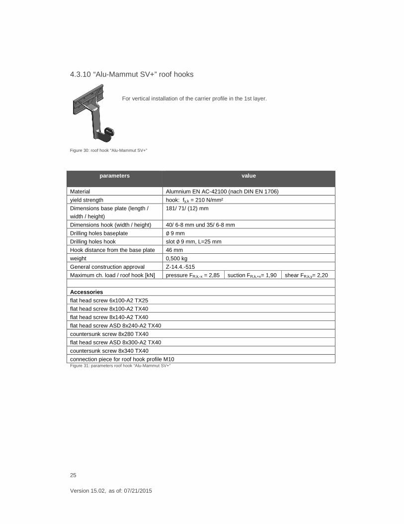
4.3.9 “Alu-Mammut S+” roof hooks
parameters value
Material Alumnium EN AC-42100 (DIN EN 1706)
yield strength hook: fy,k = 210 N/mm²
Dimensions base plate (length / width
/ height)
150/ 63,5/ (12) mm
Dimensions hook (width / height) 35/ 6-8 mm
Drilling holes baseplate ∅ 7 mm
Drilling holes hook slot ∅ 9 mm, L=25 mm
Hook distance from the base plate 46 mm
weight 0,465 kg
General construction approval Z-14.4.-515
Maximum ch. load / roof hook [kN] pressur FR,k,-x= 3,04 suction FR,k,+x= 3,14 shear FR,k,y= 3,17
Accessories
Flat head screw 6x100-A2 TX25
connection piece for roof hook profile M8 Figure 29: parameters roof hook “Alu-Mammut S+”
Figure 28: roof hook “Alu-Mammut S+”
25
Version 15.02, as of: 07/21/2015
4.3.10 “Alu-Mammut SV+” roof hooks
For vertical installation of the carrier profile in the 1st layer.
parameters value
Material Alumnium EN AC-42100 (nach DIN EN 1706)
yield strength hook: fy,k = 210 N/mm²
Dimensions base plate (length /
width / height)
181/ 71/ (12) mm
Dimensions hook (width / height) 40/ 6-8 mm und 35/ 6-8 mm
Drilling holes baseplate ∅ 9 mm
Drilling holes hook slot ∅ 9 mm, L=25 mm
Hook distance from the base plate 46 mm
weight 0,500 kg
General construction approval Z-14.4.-515
Maximum ch. load / roof hook [kN] pressure FR,k,-x = 2,85 suction FR,k,+x= 1,90 shear FR,k,y= 2,20
Accessories
flat head screw 6x100-A2 TX25
flat head screw 8x100-A2 TX40
flat head screw 8x140-A2 TX40
flat head screw ASD 8x240-A2 TX40
countersunk screw 8x280 TX40
flat head screw ASD 8x300-A2 TX40
countersunk screw 8x340 TX40
connection piece for roof hook profile M10 Figure 31: parameters roof hook “Alu-Mammut SV+”
Figure 30: roof hook “Alu-Mammut SV+”
26
Version 15.02, as of: 07/21/2015
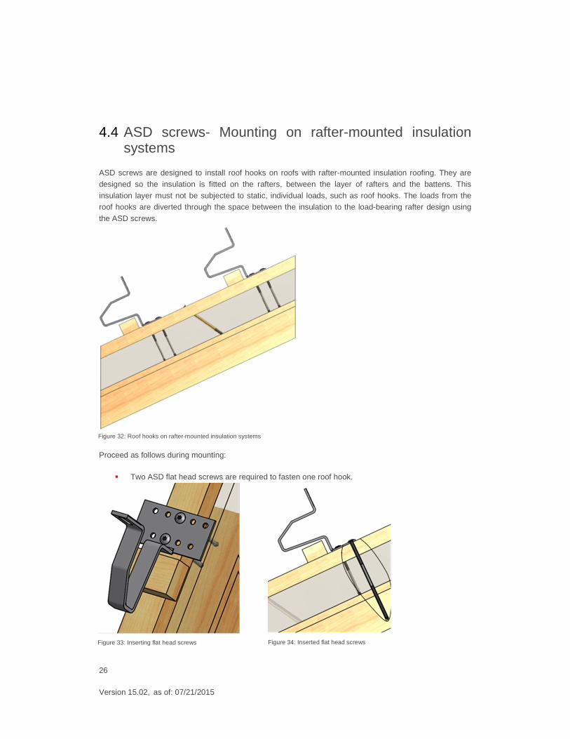
4.4 ASD screws- Mounting on rafter-mounted insulation systems
ASD screws are designed to install roof hooks on roofs with rafter-mounted insulation roofing. They are
designed so the insulation is fitted on the rafters, between the layer of rafters and the battens. This
insulation layer must not be subjected to static, individual loads, such as roof hooks. The loads from the roof hooks are diverted through the space between the insulation to the load-bearing rafter design using
the ASD screws.
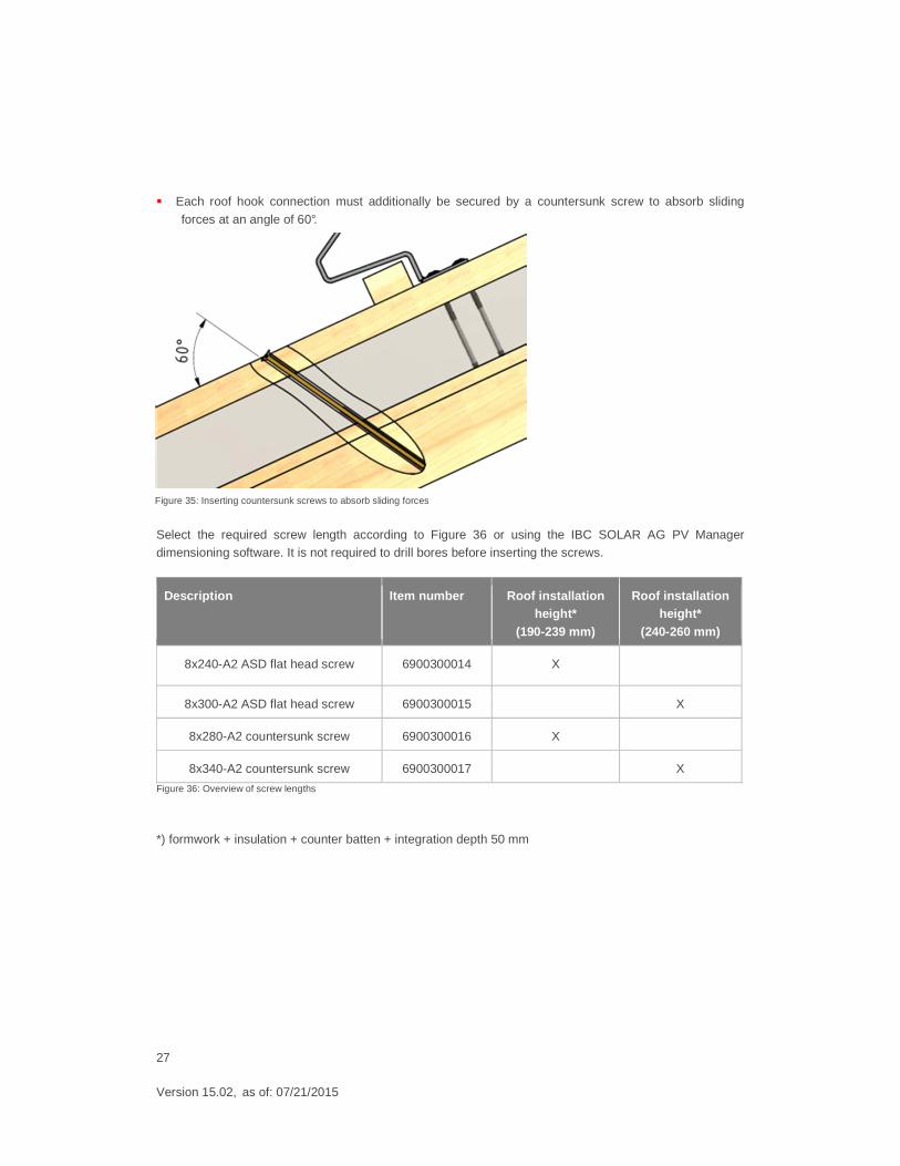
Proceed as follows during mounting:
� Two ASD flat head screws are required to fasten one roof hook.
Figure 32: Roof hooks on rafter-mounted insulation systems
Figure 33: Inserting flat head screws Figure 34: Inserted flat head screws
27
Version 15.02, as of: 07/21/2015
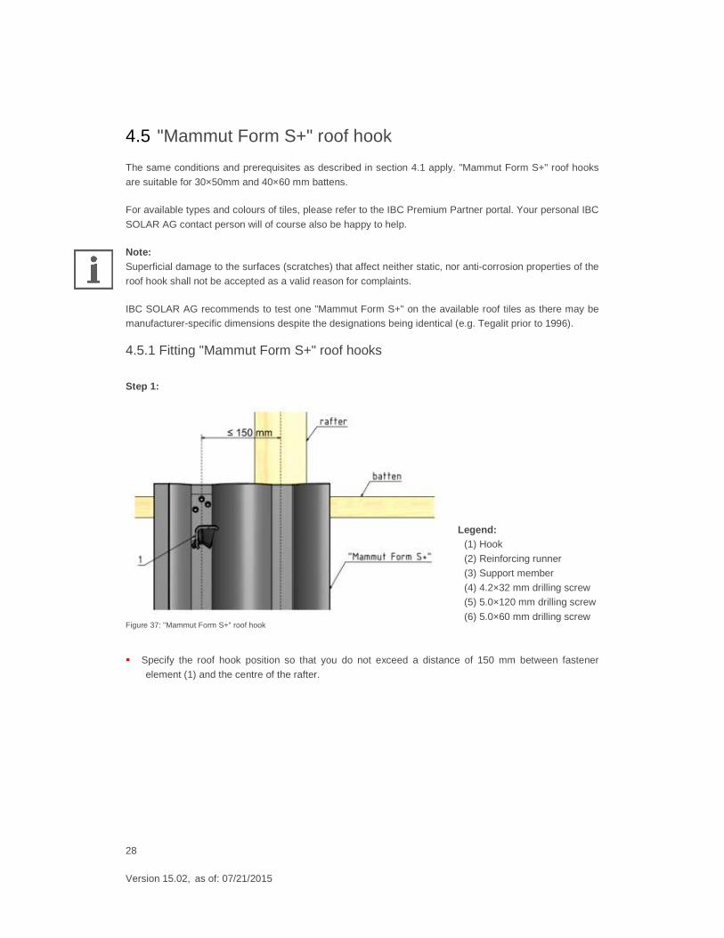
� Each roof hook connection must additionally be secured by a countersunk screw to absorb sliding
forces at an angle of 60°.
Select the required screw length according to Figure 36 or using the IBC SOLAR AG PV Manager dimensioning software. It is not required to drill bores before inserting the screws.
Description Item number Roof installation height*
(190-239 mm)
Roof installation height*
(240-260 mm)
8x240-A2 ASD flat head screw 6900300014 X
8x300-A2 ASD flat head screw 6900300015 X
8x280-A2 countersunk screw 6900300016 X
8x340-A2 countersunk screw 6900300017 X
Figure 36: Overview of screw lengths
*) formwork + insulation + counter batten + integration depth 50 mm
Figure 35: Inserting countersunk screws to absorb sliding forces
28
Version 15.02, as of: 07/21/2015
4.5 "Mammut Form S+" roof hook
The same conditions and prerequisites as described in section 4.1 apply. "Mammut Form S+" roof hooks
are suitable for 30×50mm and 40×60 mm battens.
For available types and colours of tiles, please refer to the IBC Premium Partner portal. Your personal IBC
SOLAR AG contact person will of course also be happy to help.
Note: Superficial damage to the surfaces (scratches) that affect neither static, nor anti-corrosion properties of the
roof hook shall not be accepted as a valid reason for complaints.
IBC SOLAR AG recommends to test one "Mammut Form S+" on the available roof tiles as there may be manufacturer-specific dimensions despite the designations being identical (e.g. Tegalit prior to 1996).
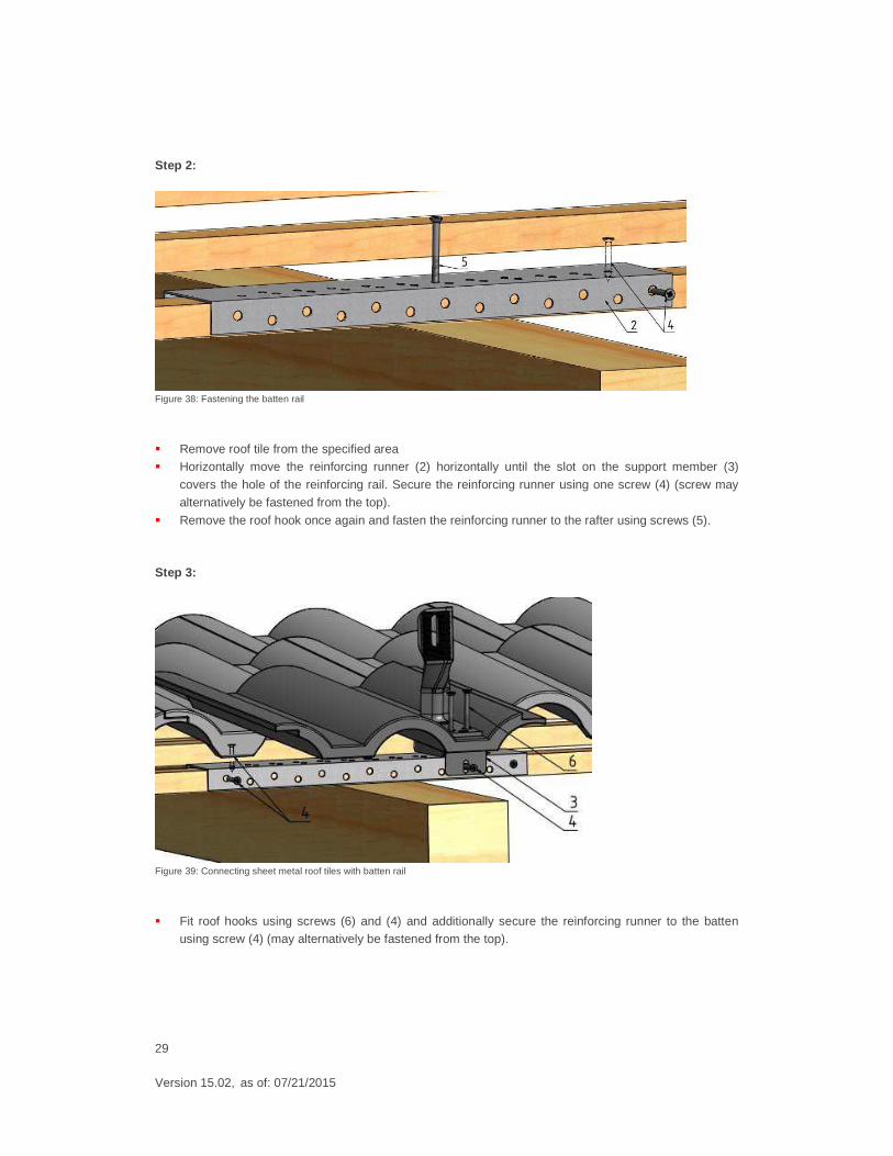
4.5.1 Fitting "Mammut Form S+" roof hooks
Step 1:
Figure 37: "Mammut Form S+" roof hook
� Specify the roof hook position so that you do not exceed a distance of 150 mm between fastener
element (1) and the centre of the rafter.
Legend: (1) Hook
(2) Reinforcing runner
(3) Support member
(4) 4.2×32 mm drilling screw (5) 5.0×120 mm drilling screw
(6) 5.0×60 mm drilling screw
29
Version 15.02, as of: 07/21/2015
Step 2:
Figure 38: Fastening the batten rail
� Remove roof tile from the specified area � Horizontally move the reinforcing runner (2) horizontally until the slot on the support member (3)
covers the hole of the reinforcing rail. Secure the reinforcing runner using one screw (4) (screw may
alternatively be fastened from the top).
� Remove the roof hook once again and fasten the reinforcing runner to the rafter using screws (5).
Step 3:
Figure 39: Connecting sheet metal roof tiles with batten rail
� Fit roof hooks using screws (6) and (4) and additionally secure the reinforcing runner to the batten using screw (4) (may alternatively be fastened from the top).
30
Version 15.02, as of: 07/21/2015
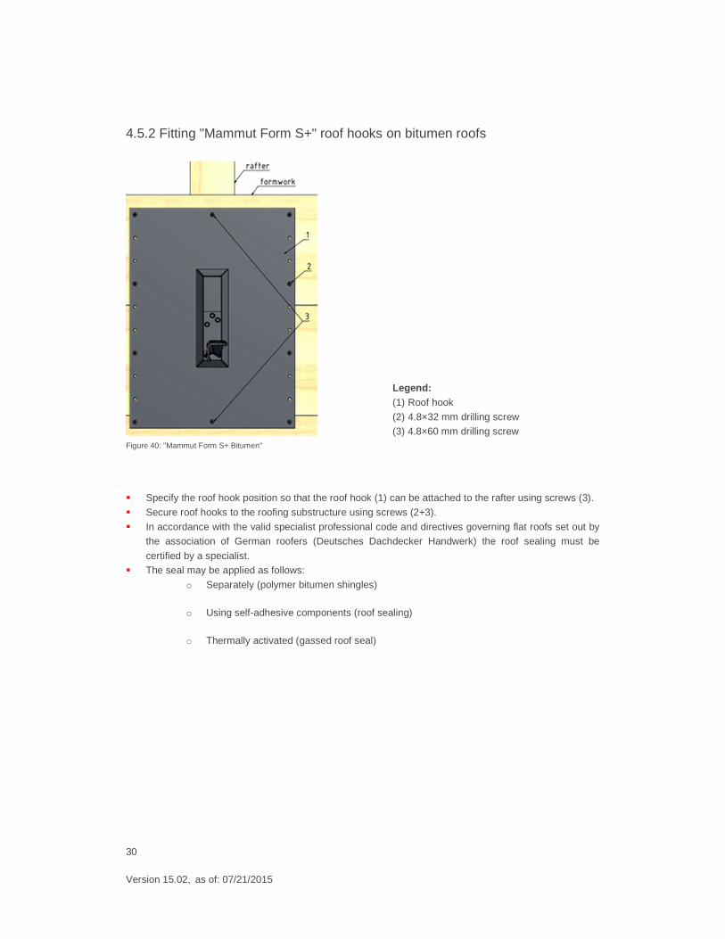
4.5.2 Fitting "Mammut Form S+" roof hooks on bitumen roofs
Figure 40: "Mammut Form S+ Bitumen"
� Specify the roof hook position so that the roof hook (1) can be attached to the rafter using screws (3).
� Secure roof hooks to the roofing substructure using screws (2+3).
� In accordance with the valid specialist professional code and directives governing flat roofs set out by the association of German roofers (Deutsches Dachdecker Handwerk) the roof sealing must be
certified by a specialist. � The seal may be applied as follows:
o Separately (polymer bitumen shingles)
o Using self-adhesive components (roof sealing)
o Thermally activated (gassed roof seal)
Legend: (1) Roof hook
(2) 4.8×32 mm drilling screw (3) 4.8×60 mm drilling screw
31
Version 15.02, as of: 07/21/2015
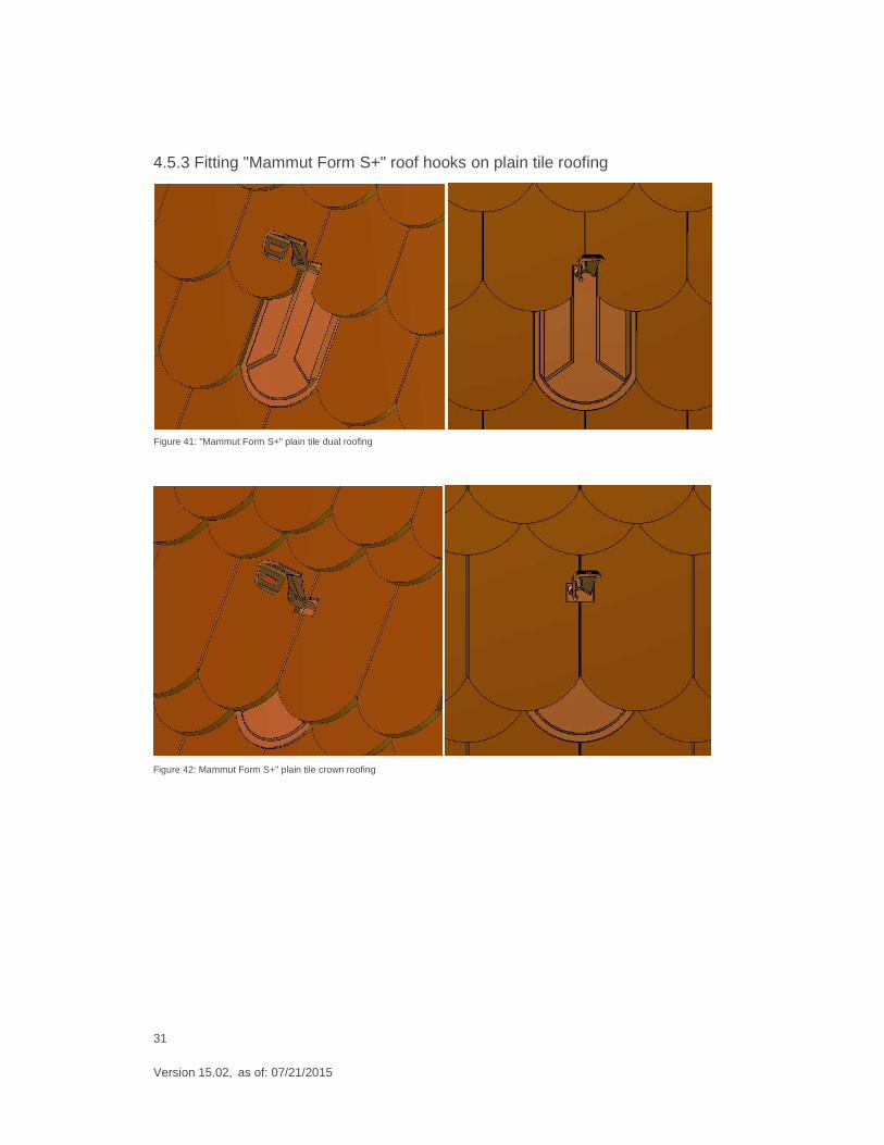
4.5.3 Fitting "Mammut Form S+" roof hooks on plain tile roofing
Figure 41: "Mammut Form S+" plain tile dual roofing
Figure 42: Mammut Form S+" plain tile crown roofing
32
Version 15.02, as of: 07/21/2015
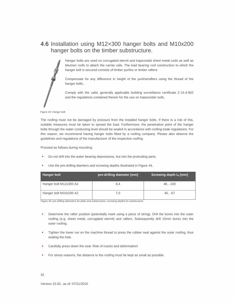
4.6 Installation using M12×300 hanger bolts and M10x200 hanger bolts on the timber substructure.
Hanger bolts are used on corrugated eternit and trapezoidal sheet metal roofs as well as
bitumen roofs to attach the carrier rails. The load bearing roof construction to which the hanger bolt is secured consists of timber purlins or timber rafters.
Compensate for any difference in height of the purlins/rafters using the thread of the hanger bolts.
Comply with the valid, generally applicable building surveillance certificate Z-14.4-602
and the regulations contained therein for the use on trapezoidal roofs.
The roofing must not be damaged by pressure from the installed hanger bolts. If there is a risk of this, suitable measures must be taken to spread the load. Furthermore, the penetration point of the hanger
bolts through the water conducting level should be sealed in accordance with roofing trade regulations. For
this reason, we recommend having hanger bolts fitted by a roofing company. Please also observe the
guidelines and regulations of the manufacturer of the respective roofing.
Proceed as follows during mounting:
� Do not drill into the water bearing depressions, but into the protruding parts.
� Use the pre-drilling diamters and screwing depths illustrated in Figure 44.
Hanger bolt pre-drilling diameter [mm] Screwing depth l ef [mm]
Hanger bolt M12x300 A2 8,4 48…100
Hanger bolt M10x200 A2 7,0 40…67
Figure 44: pre-drilling diameters for plate and substructure; screwing depths for substructure
� Determine the rafter position (potentially mark using a piece of string). Drill the bores into the outer
roofing (e.g. sheet metal, corrugated eternit) and rafters. Subsequently drill 15mm bores into the
outer roofing.
� Tighten the lower nut on the machine thread to press the rubber seal against the outer roofing, thus
sealing the hole.
� Carefully press down the seal. Risk of cracks and deformation!
� For stress reasons, the distance to the roofing must be kept as small as possible.
Figure 43: Hanger bolt
33
Version 15.02, as of: 07/21/2015
l = 1
00m
m
l = 1
00m
m
l =100 mm
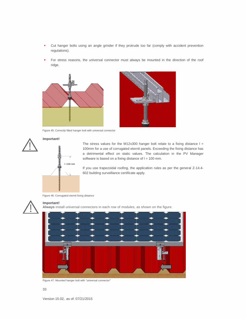
� Cut hanger bolts using an angle grinder if they protrude too far (comply with accident prevention
regulations).
� For stress reasons, the universal connector must always be mounted in the direction of the roof
ridge.
Important!
The stress values for the M12x300 hanger bolt relate to a fixing distance l = 100mm for a use of corrugated eternit panels. Exceeding the fixing distance has
a detrimental effect on static values. The calculation in the PV Manager software is based on a fixing distance of l = 100 mm.
If you use trapezoidal roofing, the application rules as per the general Z-14.4-
602 building surveillance certificate apply.
Important! Always install universal connectors in each row of modules, as shown on the figure.
Figure 45: Correctly fitted hanger bolt with universal connector
Figure 46: Corrugated eternit fixing distance
Figure 47: Mounted hanger bolt with "universal connector"
34
Version 15.02, as of: 07/21/2015
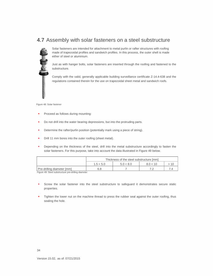
4.7 Assembly with solar fasteners on a steel substructure
Solar fasteners are intended for attachment to metal purlin or rafter structures with roofing made of trapezoidal profiles and sandwich profiles. In this process, the outer shell is made either of steel or aluminium.
Just as with hanger bolts, solar fasteners are inserted through the roofing and fastened to the
substructure.
Comply with the valid, generally applicable building surveillance certificate Z-14.4-638 and the
regulations contained therein for the use on trapezoidal sheet metal and sandwich roofs.
� Proceed as follows during mounting:
� Do not drill into the water bearing depressions, but into the protruding parts.
� Determine the rafter/purlin position (potentially mark using a piece of string).
� Drill 11 mm bores into the outer roofing (sheet metal).
� Depending on the thickness of the steel, drill into the metal substructure accordingly to fasten the solar fasteners. For this purpose, take into account the data illustrated in Figure 49 below.
Thickness of the steel substructure [mm]
1.5 < 5.0 5.0 < 8.0 8.0 < 10 > 10
Pre-drilling diameter [mm] 6.8 7 7.2 7.4 Figure 49: Steel substructure pre-drilling diameter
� Screw the solar fastener into the steel substructure to safeguard it demonstrates secure static
properties.
� Tighten the lower nut on the machine thread to press the rubber seal against the outer roofing, thus
sealing the hole.
Figure 48: Solar fastener
35
Version 15.02, as of: 07/21/2015
l = 1
00m
m
l = 1
00m
m
� Carefully press down the seal. Risk of cracks and deformation!
� For stress reasons, the universal connector must always be mounted in the direction of the roof ridge.
� Adapt the required length of the solar fastener to the height of the roof structure. Use IBC SOLAR AG's very own "PV Manager" planning software to ensure you select the right solar fastener.
Please note: Comply with the following requirements regarding the roof profile type:
� The nominal sheet metal profile panel thickness around the fasteners is ≥ 0.4 mm for steel and ≥ 0.5
mm for aluminium.
� The nominal width of the outer layer of the sandwich element around the fasteners is ≥ 0.4 mm.
� The nominal width of the steel substructure (rafters/purlins) around the fasteners is ≥ 1.5 mm.
� The available rib height h for sandwich roofs is 35 mm ≤ h ≤ 45 mm
� The available upper belt width b for sandwich roofs is 20 mm ≤ b ≤ 40 mm
� When putting a load on solar fasteners in a transverse direction to the profile panels, the profile
panels must be fastened to the corrugated elements on the substructure that are in the vicinity and at the same height.
� For additional framework conditions, see the valid version of the Z-14.4-638 certificate.
36
Version 15.02, as of: 07/21/2015
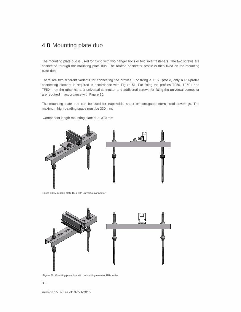
4.8 Mounting plate duo
The mounting plate duo is used for fixing with two hanger bolts or two solar fasteners. The two screws are connected through the mounting plate duo. The rooftop connector profile is then fixed on the mounting
plate duo.
There are two different variants for connecting the profiles. For fixing a TF60 profile, only a RH-profile connecting element is required in accordance with Figure 51. For fixing the profiles TF50, TF50+ and
TF50m, on the other hand, a universal connector and additional screws for fixing the universal connector
are required in accordance with Figure 50.
The mounting plate duo can be used for trapezoidal sheet or corrugated eternit roof coverings. The maximum high-beading space must be 330 mm.
Component length mounting plate duo: 370 mm
Figure 50: Mounting plate Duo with universal connector
Figure 51: Mounting plate duo with connecting element RH-profile
37
Version 15.02, as of: 07/21/2015
4.9 Mounting with trapezoidal sheet metal clamps
4.9.1 Introduction
IBC SOLAR AG trapezoidal sheet metal mounting in combination with the IBC TopFix 200 mounting
system is a fast, universal and structurally tested solution for attaching solar modules onto trapezoidal sheet metal roofs.
Please note: � The minimum trapezoidal sheet metal or aluminium thickness must be 0.5 mm.
� The enclosed special 4.8×15 blind rivets with flat, round head are certified for a sheet metal thickness of between 0.5 mm and 1.9 mm.
� Do not fall below the raised bead support width of 15 mm.
� The maximum width b of the raised bead must not exceed 40 mm.
� Because additional loads are created by the PV system in connection with the IBC mounting system
and fixing points (fixed-points) and wind suction, the installer (contractor) has to check the statics of
the load capacity of the roofing and the substructure, which normally requires the services of a structural engineer.
� Special-purpose assembly on narrow raised beads, sandwich elements and elevations must be verified on-site as part of individual statics inspections and a certificate for sandwich profiles may
have to be obtained from building surveillance authorities.
Important: Do not mount trapezoidal sheet clamps on the trapezoidal sheet metal panel blocks (two layers
of sheet metal)!
4.9.2 Required tools/auxiliary agents
� Riveter
� Drill, Ø 5.0 mm
� Cleaning agent (isopropyl alcohol, acetone 6000300002)
� Lint-free paper towels
� Cleaning fleece for badly contaminated roofs (6000300003)
* The listed tools and auxiliary agents are required exclusively for installation and processing of the trapezoidal sheet metal panels.
Information about tools for module and carrier rail mounting is provided in section 1 in these installation
instructions.
38
Version 15.02, as of: 07/21/2015
4.9.3 Dimensioning
The mounting system is dimensioned in our very own PV Manager software, taking into account local conditions.
Important: Do no exceed a maximum carrier profile length of 3 beams (approximately 15.60 m) for continuous carrier
rails due to thermal expansion.
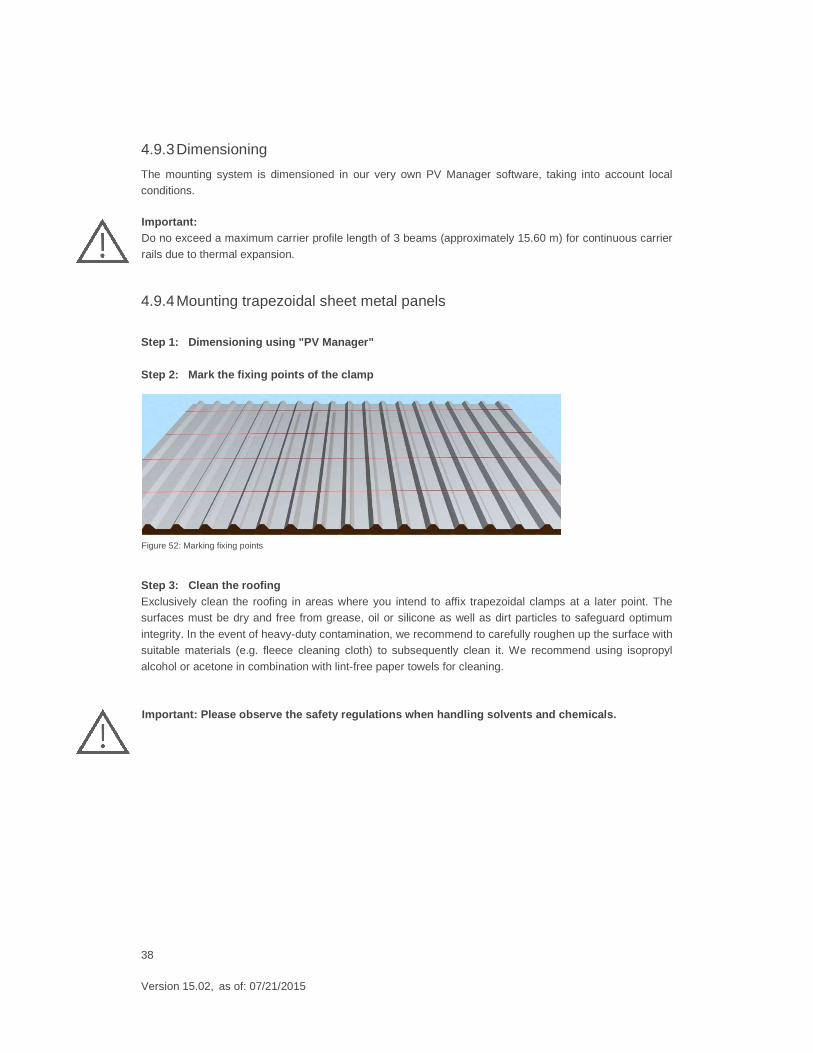
4.9.4 Mounting trapezoidal sheet metal panels
Step 1: Dimensioning using "PV Manager" Step 2: Mark the fixing points of the clamp
Step 3: Clean the roofing Exclusively clean the roofing in areas where you intend to affix trapezoidal clamps at a later point. The surfaces must be dry and free from grease, oil or silicone as well as dirt particles to safeguard optimum
integrity. In the event of heavy-duty contamination, we recommend to carefully roughen up the surface with suitable materials (e.g. fleece cleaning cloth) to subsequently clean it. We recommend using isopropyl
alcohol or acetone in combination with lint-free paper towels for cleaning.
Important: Please observe the safety regulations when handling solvents and chemicals.
Figure 52: Marking fixing points
39
Version 15.02, as of: 07/21/2015
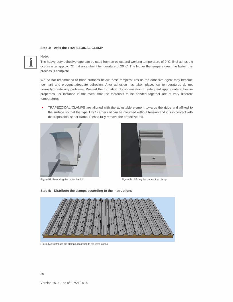
Step 4: Affix the TRAPEZOIDAL CLAMP
Note:
The heavy-duty adhesive tape can be used from an object and working temperature of 0° C; final adhesio n
occurs after approx. 72 h at an ambient temperature of 20° C. The higher the temperatures, the faster this process is complete.
We do not recommend to bond surfaces below these temperatures as the adhesive agent may become too hard and prevent adequate adhesion. After adhesion has taken place, low temperatures do not
normally create any problems. Prevent the formation of condensation to safeguard appropriate adhesive
properties, for instance in the event that the materials to be bonded together are at very different
temperatures.
� TRAPEZOIDAL CLAMPS are aligned with the adjustable element towards the ridge and affixed to
the surface so that the type TF27 carrier rail can be mounted without tension and it is in contact with the trapezoidal sheet clamp. Please fully remove the protective foil!
Figure 53: Removing the protective foil Figure 54: Affixing the trapezoidal clamp
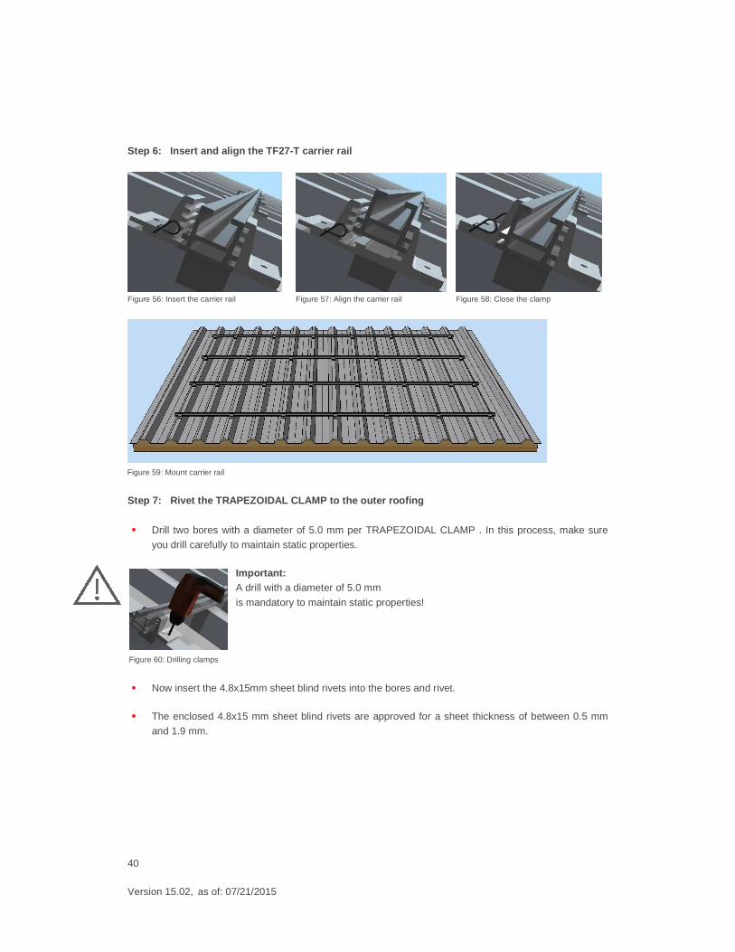
Step 5: Distribute the clamps according to the instructions
Figure 55: Distribute the clamps according to the instructions
40
Version 15.02, as of: 07/21/2015
Step 6: Insert and align the TF27-T carrier rail
Figure 56: Insert the carrier rail Figure 57: Align the carrier rail Figure 58: Close the clamp
Step 7: Rivet the TRAPEZOIDAL CLAMP to the outer roofing
� Drill two bores with a diameter of 5.0 mm per TRAPEZOIDAL CLAMP . In this process, make sure
you drill carefully to maintain static properties.
Important: A drill with a diameter of 5.0 mm
is mandatory to maintain static properties!
� Now insert the 4.8x15mm sheet blind rivets into the bores and rivet.
� The enclosed 4.8x15 mm sheet blind rivets are approved for a sheet thickness of between 0.5 mm
and 1.9 mm.
Figure 59: Mount carrier rail
Figure 60: Drilling clamps
41
Version 15.02, as of: 07/21/2015
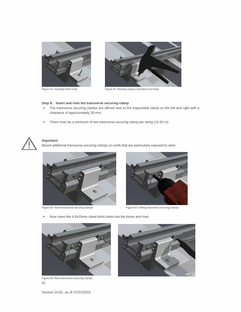
Figure 61: Inserting blind rivets Figure 62: Riveting using a standard rivet head
Step 8: Insert and rivet the transverse securing clamp � The transverse securing clamps are affixed next to the trapezoidal clamp on the left and right with a
clearance of approximately 20 mm.
� There must be a minimum of two transverse securing clamp per string (15.60 m).
Important: Mount additional transverse securing clamps on roofs that are particularly exposed to wind.
Figure 63: Insert transverse securing clamps Figure 64: Drilling transverse securing clamps
� Now insert the 4.8x15mm sheet blind rivets into the bores and rivet.
Figure 65: Rivet transverse securing clamps
42
Version 15.02, as of: 07/21/2015
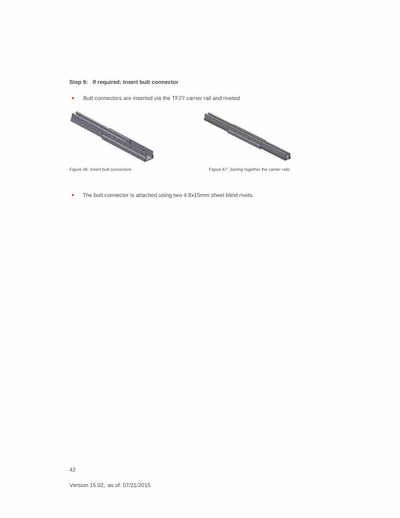
Step 9: If required: Insert butt connector
� Butt connectors are inserted via the TF27 carrier rail and riveted
Figure 66: Insert butt connectors Figure 67: Joining together the carrier rails
� The butt connector is attached using two 4.8x15mm sheet blind rivets.
43
Version 15.02, as of: 07/21/2015
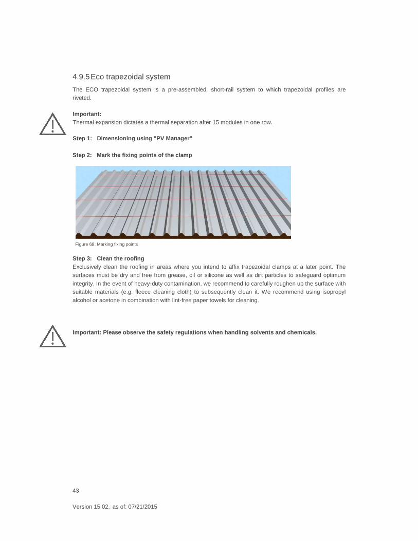
4.9.5 Eco trapezoidal system
The ECO trapezoidal system is a pre-assembled, short-rail system to which trapezoidal profiles are riveted.
Important: Thermal expansion dictates a thermal separation after 15 modules in one row.
Step 1: Dimensioning using "PV Manager" Step 2: Mark the fixing points of the clamp
Step 3: Clean the roofing Exclusively clean the roofing in areas where you intend to affix trapezoidal clamps at a later point. The surfaces must be dry and free from grease, oil or silicone as well as dirt particles to safeguard optimum
integrity. In the event of heavy-duty contamination, we recommend to carefully roughen up the surface with suitable materials (e.g. fleece cleaning cloth) to subsequently clean it. We recommend using isopropyl
alcohol or acetone in combination with lint-free paper towels for cleaning.
Important: Please observe the safety regulations when handling solvents and chemicals.
Figure 68: Marking fixing points
44
Version 15.02, as of: 07/21/2015
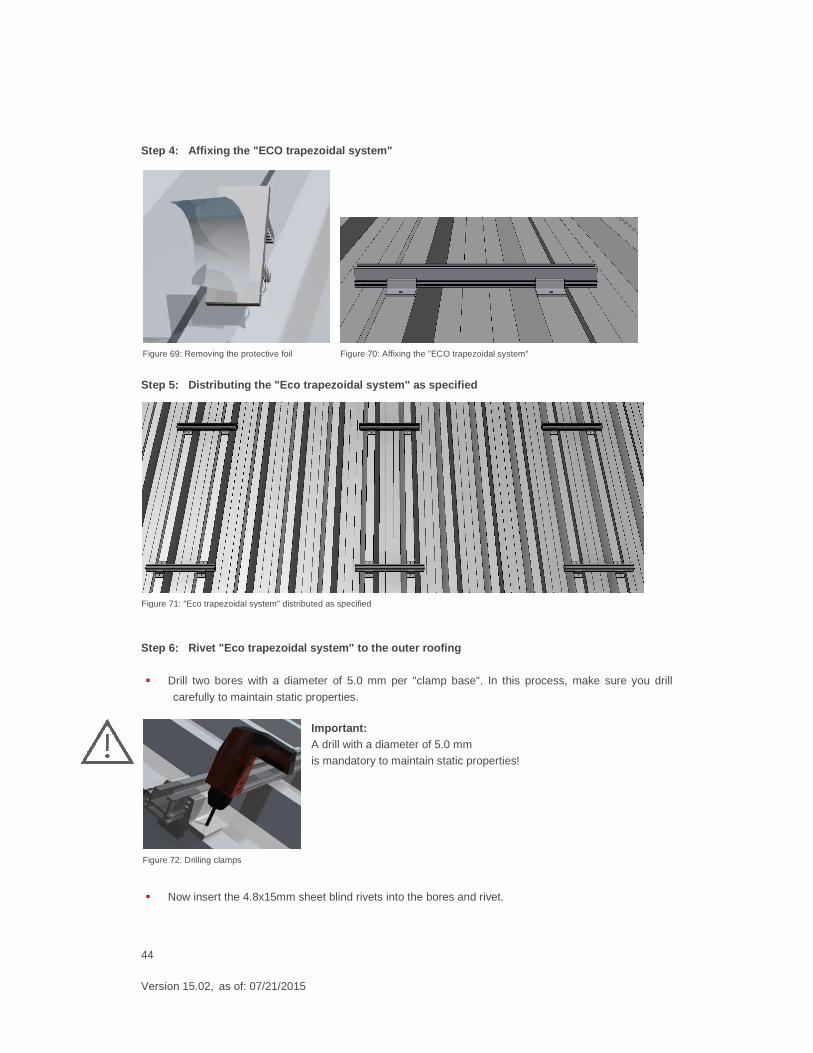
Step 4: Affixing the "ECO trapezoidal system"
Step 5: Distributing the "Eco trapezoidal system" as specif ied
Step 6: Rivet "Eco trapezoidal system" to the out er roofing
� Drill two bores with a diameter of 5.0 mm per "clamp base". In this process, make sure you drill
carefully to maintain static properties.
Important: A drill with a diameter of 5.0 mm
is mandatory to maintain static properties!
� Now insert the 4.8x15mm sheet blind rivets into the bores and rivet.
Figure 69: Removing the protective foil Figure 70: Affixing the "ECO trapezoidal system"
Figure 71: "Eco trapezoidal system" distributed as specified
Figure 72: Drilling clamps
45
Version 15.02, as of: 07/21/2015
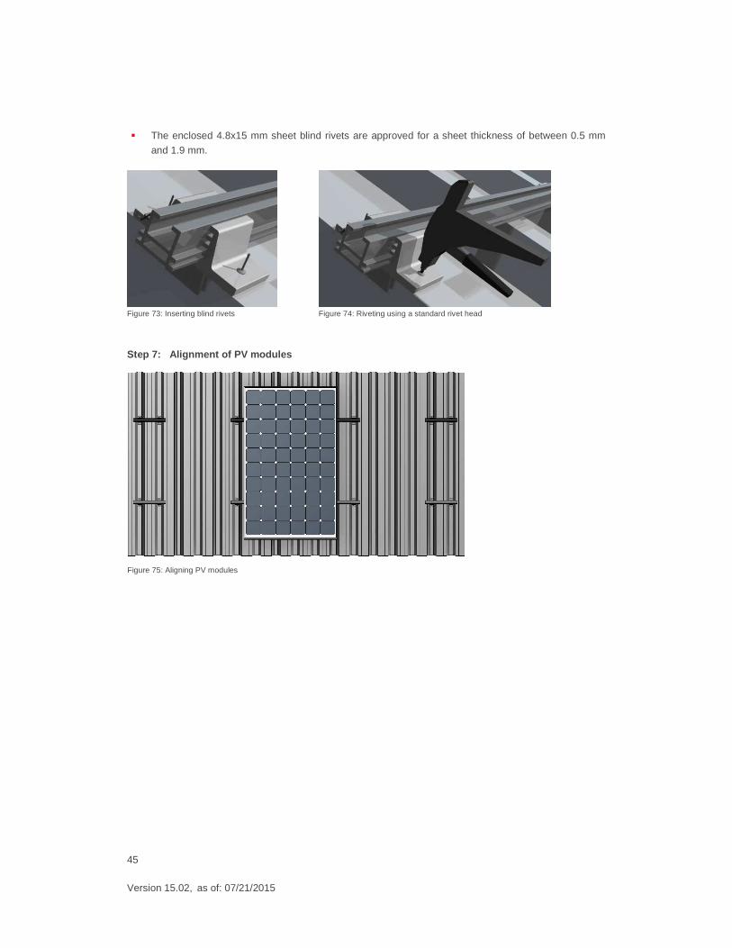
� The enclosed 4.8x15 mm sheet blind rivets are approved for a sheet thickness of between 0.5 mm
and 1.9 mm.
Figure 73: Inserting blind rivets Figure 74: Riveting using a standard rivet head
Step 7: Alignment of PV modules
Figure 75: Aligning PV modules
46
Version 15.02, as of: 07/21/2015
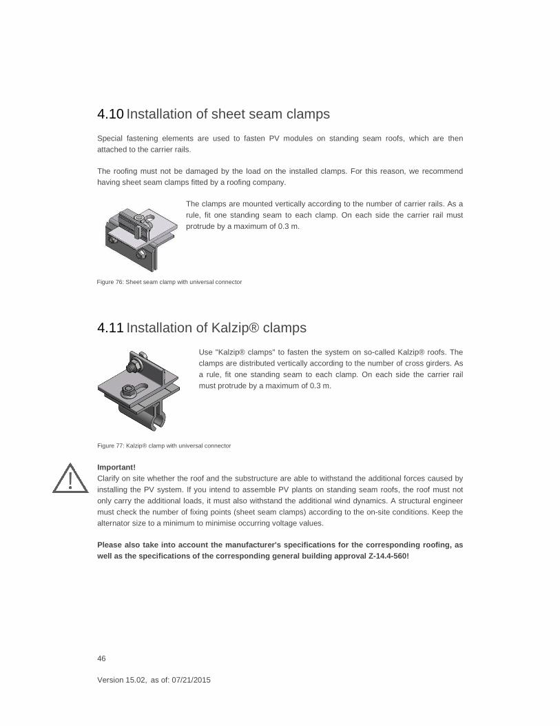
4.10 Installation of sheet seam clamps
Special fastening elements are used to fasten PV modules on standing seam roofs, which are then attached to the carrier rails.
The roofing must not be damaged by the load on the installed clamps. For this reason, we recommend having sheet seam clamps fitted by a roofing company.
The clamps are mounted vertically according to the number of carrier rails. As a
rule, fit one standing seam to each clamp. On each side the carrier rail must
protrude by a maximum of 0.3 m.
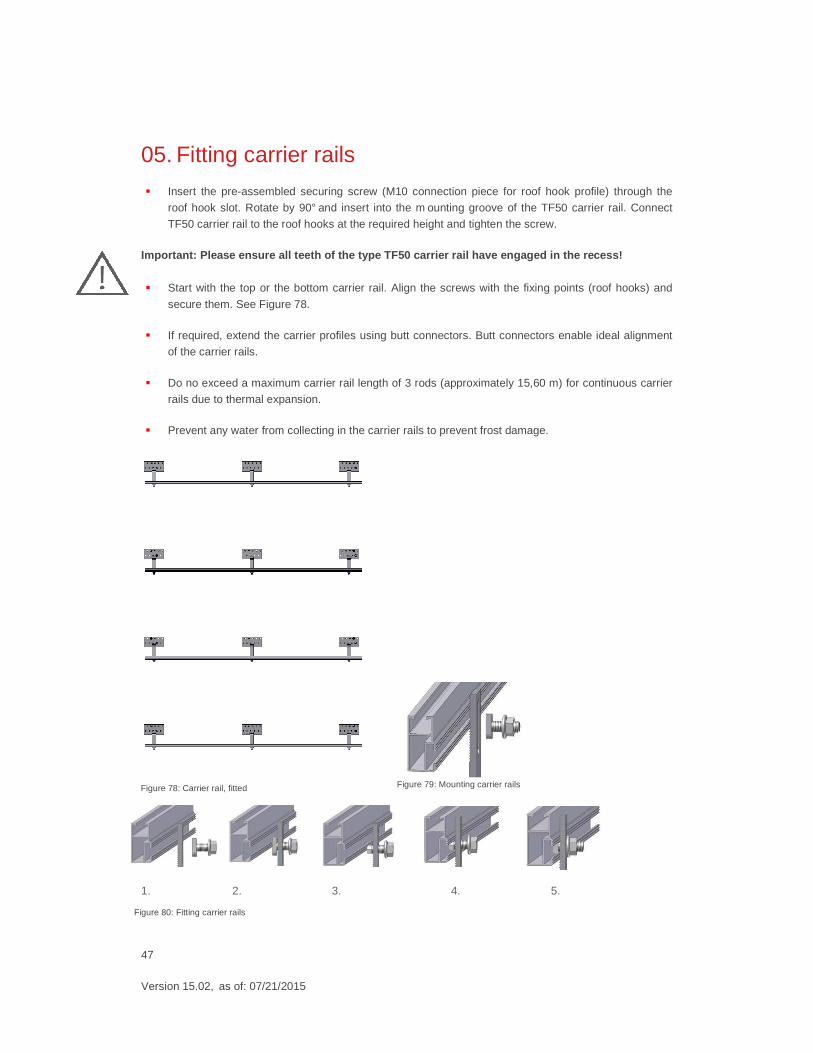
4.11 Installation of Kalzip® clamps
Use "Kalzip® clamps" to fasten the system on so-called Kalzip® roofs. The clamps are distributed vertically according to the number of cross girders. As
a rule, fit one standing seam to each clamp. On each side the carrier rail
must protrude by a maximum of 0.3 m.
Important! Clarify on site whether the roof and the substructure are able to withstand the additional forces caused by
installing the PV system. If you intend to assemble PV plants on standing seam roofs, the roof must not
only carry the additional loads, it must also withstand the additional wind dynamics. A structural engineer
must check the number of fixing points (sheet seam clamps) according to the on-site conditions. Keep the alternator size to a minimum to minimise occurring voltage values.
Please also take into account the manufacturer's sp ecifications for the corresponding roofing, as well as the specifications of the corresponding gen eral building approval Z-14.4-560!
Figure 76: Sheet seam clamp with universal connector
Figure 77: Kalzip® clamp with universal connector
47
Version 15.02, as of: 07/21/2015
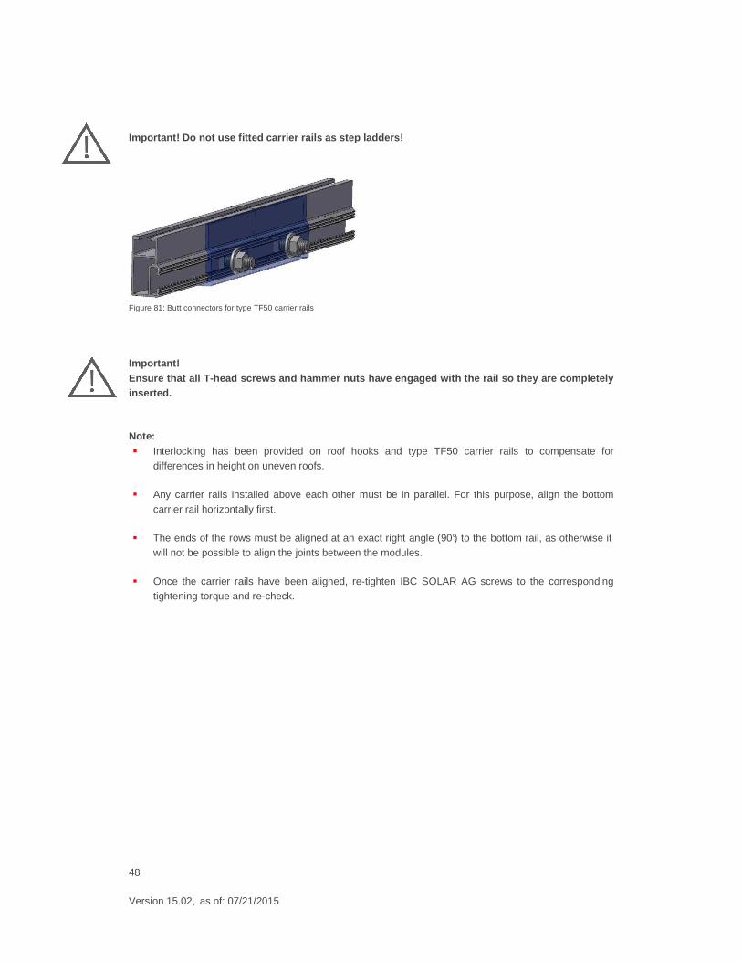
05. Fitting carrier rails
� Insert the pre-assembled securing screw (M10 connection piece for roof hook profile) through the
roof hook slot. Rotate by 90° and insert into the m ounting groove of the TF50 carrier rail. Connect
TF50 carrier rail to the roof hooks at the required height and tighten the screw.
Important: Please ensure all teeth of the type TF50 carrier ra il have engaged in the recess!
� Start with the top or the bottom carrier rail. Align the screws with the fixing points (roof hooks) and
secure them. See Figure 78.
� If required, extend the carrier profiles using butt connectors. Butt connectors enable ideal alignment
of the carrier rails.
� Do no exceed a maximum carrier rail length of 3 rods (approximately 15,60 m) for continuous carrier
rails due to thermal expansion.
� Prevent any water from collecting in the carrier rails to prevent frost damage.
1. 2. 3. 4. 5.
Figure 78: Carrier rail, fitted Figure 79: Mounting carrier rails
Figure 80: Fitting carrier rails
48
Version 15.02, as of: 07/21/2015
Important! Do not use fitted carrier rails as step ladders!
Figure 81: Butt connectors for type TF50 carrier rails
Important! Ensure that all T-head screws and hammer nuts have engaged with the rail so they are completely inserted.
Note: � Interlocking has been provided on roof hooks and type TF50 carrier rails to compensate for
differences in height on uneven roofs.
� Any carrier rails installed above each other must be in parallel. For this purpose, align the bottom
carrier rail horizontally first.
� The ends of the rows must be aligned at an exact right angle (90°) to the bottom rail, as otherwise it will not be possible to align the joints between the modules.
� Once the carrier rails have been aligned, re-tighten IBC SOLAR AG screws to the corresponding tightening torque and re-check.
49
Version 15.02, as of: 07/21/2015
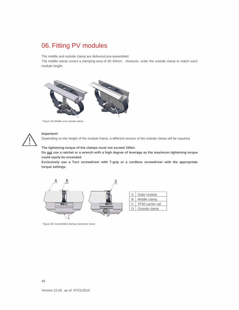
06. Fitting PV modules
The middle and outside clamp are delivered pre-assembled.
The middle clamp covers a clamping area of 30–50mm. However, order the outside clamp to match each
module height.
Important! Depending on the height of the module frame, a different version of the outside clamp will be required.
The tightening torque of the clamps must not exceed 15Nm. Do not use a ratchet or a wrench with a high degree of leverage as the maximum tightening torque could easily be exceeded. Exclusively use a Torx screwdriver with T-grip or a cordless screwdriver with the appropriate torque settings.
A Solar module B Middle clamp C TF50 carrier rail D Outside clamp
Figure 82 Middle and outside clamp
Figure 83: Assembled clamps (sectional view)
50
Version 15.02, as of: 07/21/2015
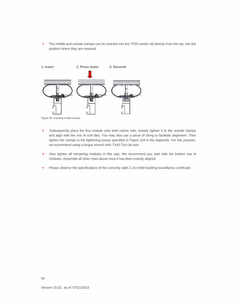
� The middle and outside clamps can be inserted into the TF50 carrier rail directly from the top, into the
position where they are required.
1. Insert 2. Press down 3. Secured
Figure 84: Inserting middle clamps
� Subsequently place the first module onto both carrier rails, loosely tighten it to the outside clamps
and align with the row of roof tiles. You may also use a piece of string to facilitate alignment. Then
tighten the clamps to the tightening torque specified in Figure 104 in the Appendix. For this purpose,
we recommend using a torque wrench with TX40 Torx bit size.
� Also tighten all remaining modules in this way. We recommend you start with the bottom row of
modules. Assemble all other rows above once it has been exactly aligned.
� Please observe the specifications of the currently valid Z-14.4-660 building surveillance certificate.
51
Version 15.02, as of: 07/21/2015
07. Fitting cable clips
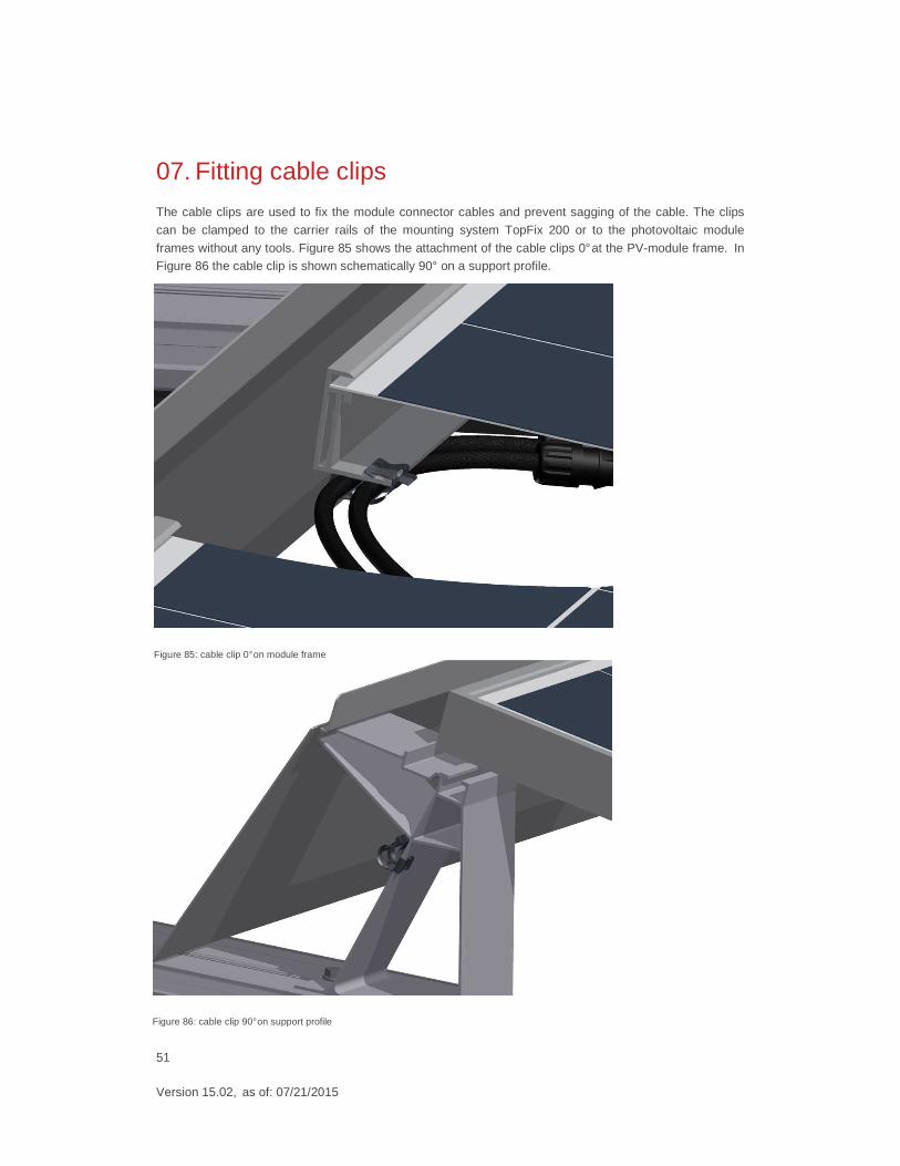
The cable clips are used to fix the module connector cables and prevent sagging of the cable. The clips
can be clamped to the carrier rails of the mounting system TopFix 200 or to the photovoltaic module
frames without any tools. Figure 85 shows the attachment of the cable clips 0° at the PV-module frame. In Figure 86 the cable clip is shown schematically 90° on a support profile.
Figure 85: cable clip 0° on module frame
Figure 86: cable clip 90° on support profile
52
Version 15.02, as of: 07/21/2015
08. Fitting the two-layer carrier system
8.1 General information
In contrast to single-layer carrier rails, this method additionally employs carrier rails as so-called roof hook
connecting rails before the actual carrier rail is fitted.
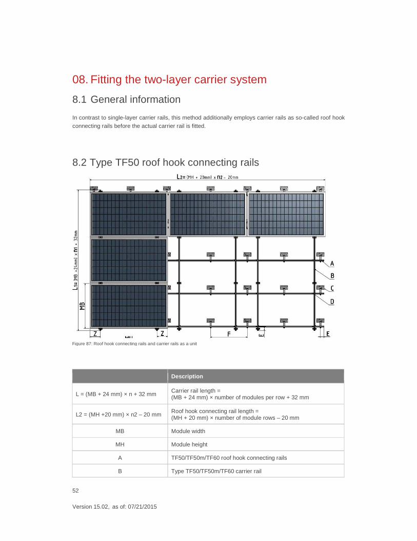
8.2 Type TF50 roof hook connecting rails
Description
L = (MB + 24 mm) × n + 32 mm Carrier rail length = (MB + 24 mm) × number of modules per row + 32 mm
L2 = (MH +20 mm) × n2 – 20 mm Roof hook connecting rail length = (MH + 20 mm) × number of module rows – 20 mm
MB Module width
MH Module height
A TF50/TF50m/TF60 roof hook connecting rails
B Type TF50/TF50m/TF60 carrier rail
Figure 87: Roof hook connecting rails and carrier rails as a unit
53
Version 15.02, as of: 07/21/2015
Dimensioning: Two-layer systems are dimensioned in the same way as single-layer systems. However, the following
special features must be taken into account:
� Plan for one roof hook per area where carrier rail and roof hook connecting rail meet.
� Please also take into account the static values of roof hook connecting rails in addition to the roof
hooks and carrier profiles. Use the PV Manager software to determine the static dimensions.
� We do not recommend you exceed a maximum carrier rail length of 3 rods (approximately 15,60 m) due to thermal expansion.
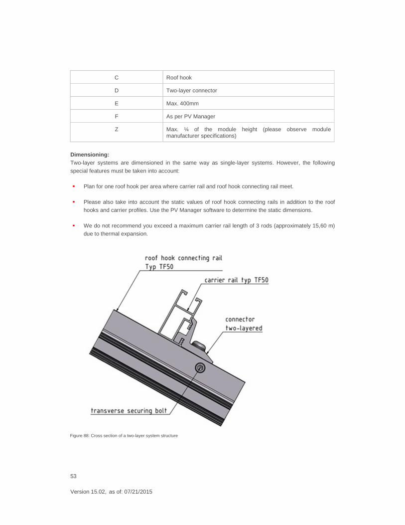
C Roof hook
D Two-layer connector
E Max. 400mm
F As per PV Manager
Z Max. ¼ of the module height (please observe module manufacturer specifications)
Figure 88: Cross section of a two-layer system structure
54
Version 15.02, as of: 07/21/2015
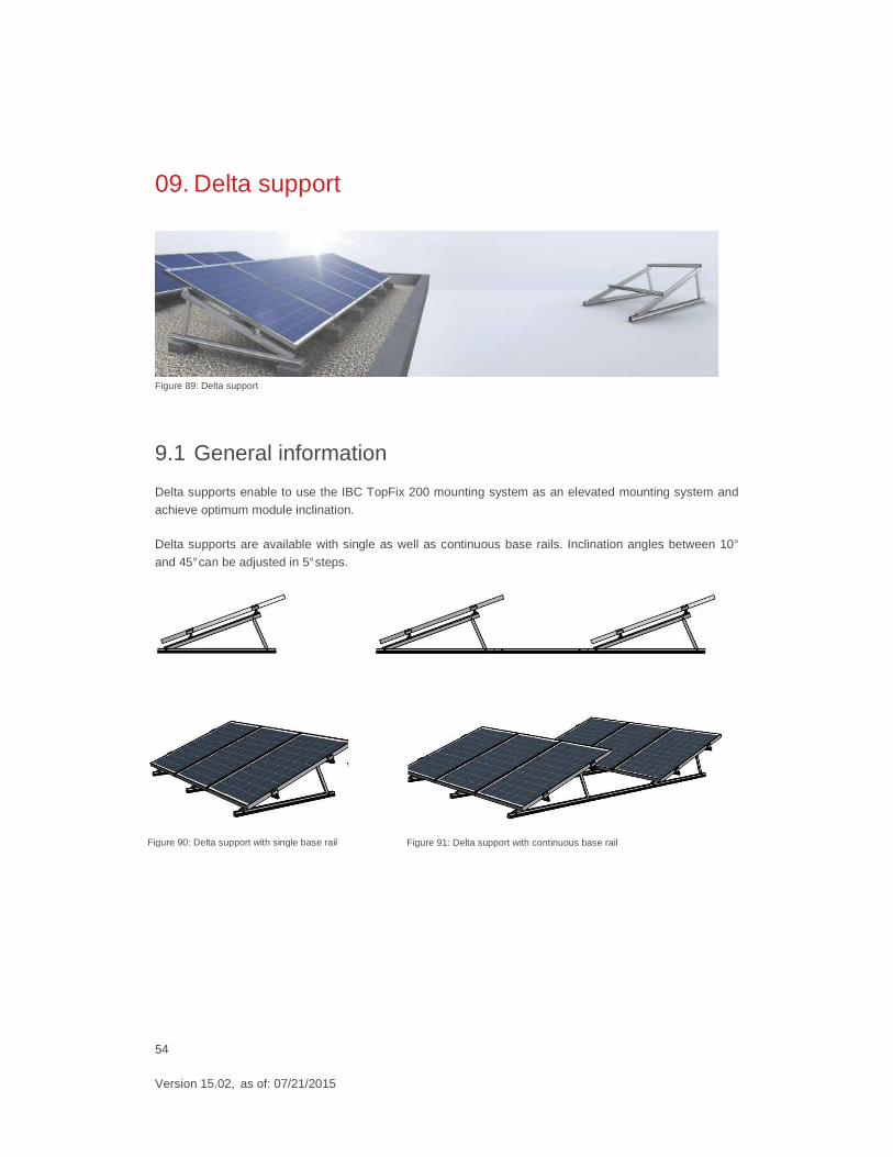
09. Delta support
Figure 89: Delta support
9.1 General information
Delta supports enable to use the IBC TopFix 200 mounting system as an elevated mounting system and
achieve optimum module inclination.
Delta supports are available with single as well as continuous base rails. Inclination angles between 10°
and 45° can be adjusted in 5° steps.
Figure 90: Delta support with single base rail Figure 91: Delta support with continuous base rail
55
Version 15.02, as of: 07/21/2015
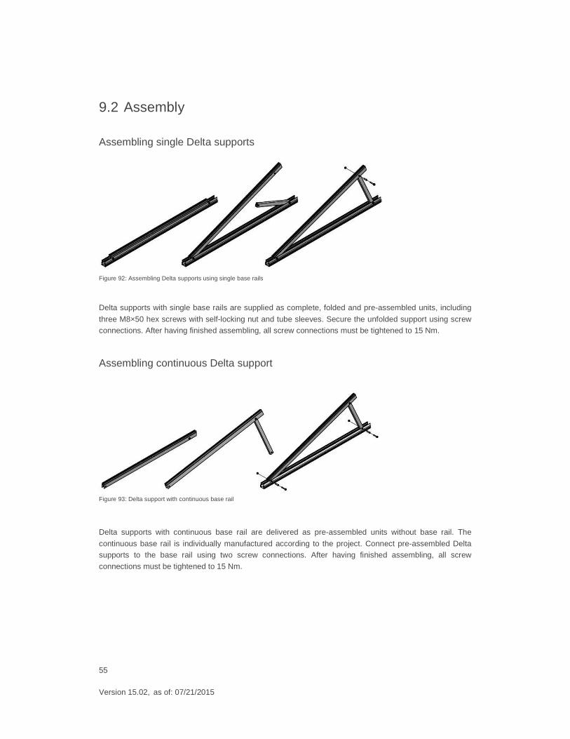
9.2 Assembly
Assembling single Delta supports
Figure 92: Assembling Delta supports using single base rails
Delta supports with single base rails are supplied as complete, folded and pre-assembled units, including
three M8×50 hex screws with self-locking nut and tube sleeves. Secure the unfolded support using screw connections. After having finished assembling, all screw connections must be tightened to 15 Nm.
Assembling continuous Delta support
Figure 93: Delta support with continuous base rail
Delta supports with continuous base rail are delivered as pre-assembled units without base rail. The
continuous base rail is individually manufactured according to the project. Connect pre-assembled Delta supports to the base rail using two screw connections. After having finished assembling, all screw
connections must be tightened to 15 Nm.
56
Version 15.02, as of: 07/21/2015
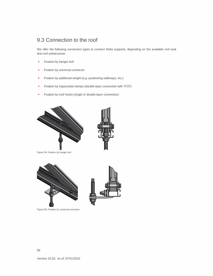
9.3 Connection to the roof
We offer the following connection types to connect Delta supports, depending on the available roof seal
and roof substructure:
� Fixation by hanger bolt
� Fixation by universal connector
� Fixation by additional weight (e.g. positioning walkways, etc.)
� Fixation by trapezoidal clamps (double-layer connection with TF27)
� Fixation by roof hooks (single or double-layer connection)
Figure 94: Fixation by hanger bolt
Figure 95: Fixation by universal connector
57
Version 15.02, as of: 07/21/2015
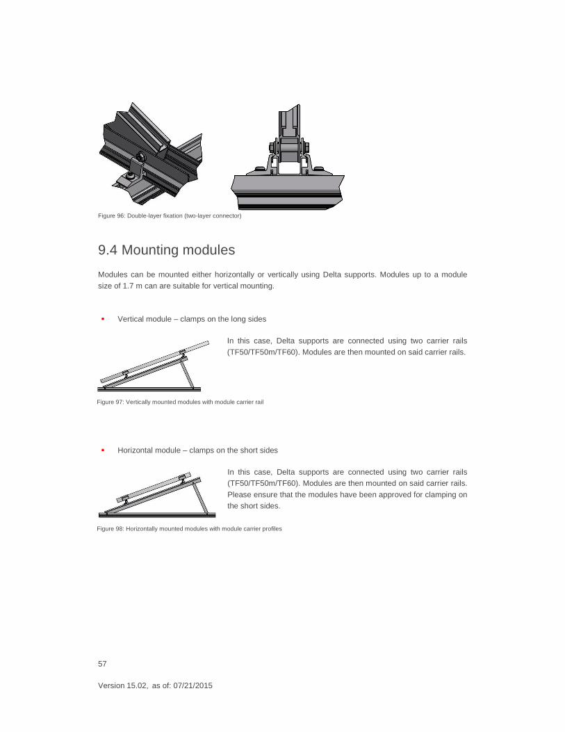
Figure 96: Double-layer fixation (two-layer connector)
9.4 Mounting modules
Modules can be mounted either horizontally or vertically using Delta supports. Modules up to a module
size of 1.7 m can are suitable for vertical mounting.
� Vertical module – clamps on the long sides
In this case, Delta supports are connected using two carrier rails
(TF50/TF50m/TF60). Modules are then mounted on said carrier rails.
� Horizontal module – clamps on the short sides
In this case, Delta supports are connected using two carrier rails (TF50/TF50m/TF60). Modules are then mounted on said carrier rails.
Please ensure that the modules have been approved for clamping on the short sides.
Figure 97: Vertically mounted modules with module carrier rail
Figure 98: Horizontally mounted modules with module carrier profiles
58
Version 15.02, as of: 07/21/2015
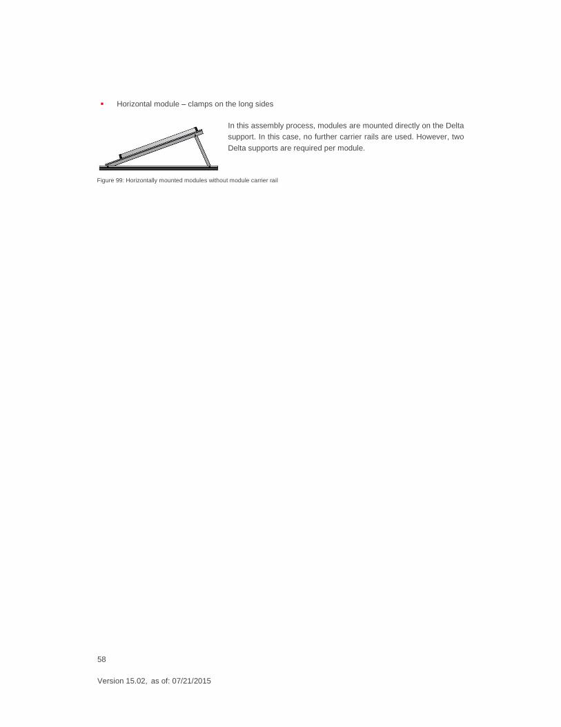
� Horizontal module – clamps on the long sides
In this assembly process, modules are mounted directly on the Delta support. In this case, no further carrier rails are used. However, two
Delta supports are required per module.
Figure 99: Horizontally mounted modules without module carrier rail
59
Version 15.02, as of: 07/21/2015
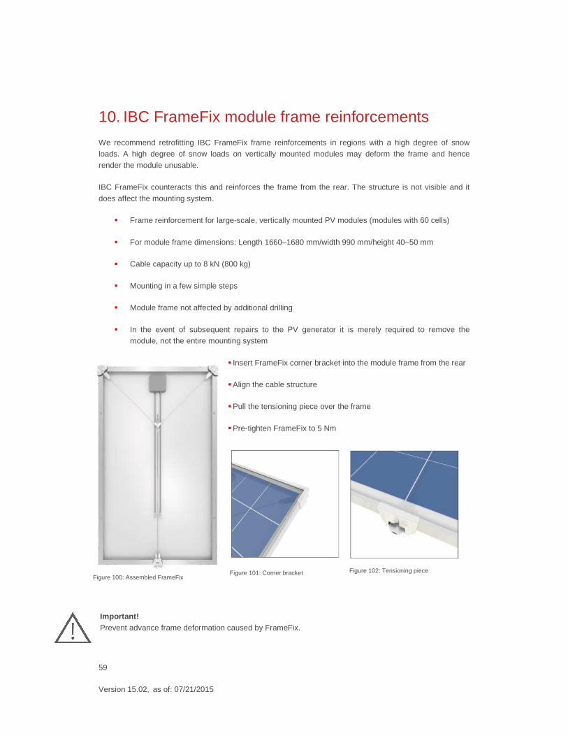
10. IBC FrameFix module frame reinforcements
We recommend retrofitting IBC FrameFix frame reinforcements in regions with a high degree of snow loads. A high degree of snow loads on vertically mounted modules may deform the frame and hence
render the module unusable.
IBC FrameFix counteracts this and reinforces the frame from the rear. The structure is not visible and it
does affect the mounting system.
� Frame reinforcement for large-scale, vertically mounted PV modules (modules with 60 cells)
� For module frame dimensions: Length 1660–1680 mm/width 990 mm/height 40–50 mm
� Cable capacity up to 8 kN (800 kg)
� Mounting in a few simple steps
� Module frame not affected by additional drilling
� In the event of subsequent repairs to the PV generator it is merely required to remove the module, not the entire mounting system
� Insert FrameFix corner bracket into the module frame from the rear
� Align the cable structure
� Pull the tensioning piece over the frame
� Pre-tighten FrameFix to 5 Nm
Important! Prevent advance frame deformation caused by FrameFix.
Figure 100: Assembled FrameFix Figure 101: Corner bracket Figure 102: Tensioning piece
60
Version 15.02, as of: 07/21/2015
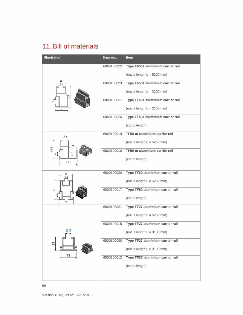
11. Bill of materials
Illustration Item no.: Item
6800100022 Type TF50+ aluminium carrier rail
(uncut length L = 5200 mm)
6800100023 Type TF50+ aluminium carrier rail
(uncut length L = 3100 mm)
6800100027 Type TF50+ aluminium carrier rail
(uncut length L = 2100 mm)
6800100024 Type TF50+ aluminium carrier rail
(cut to length)
6800100019 TF50-m aluminium carrier rail
(uncut length L = 5200 mm)
6800100010 TF50-m aluminium carrier rail
(cut to length)
6800100020 Type TF60 aluminium carrier rail
(uncut length L = 5200 mm)
6800100017 Type TF60 aluminium carrier rail
(cut to length)
6800100021 Type TF27 aluminium carrier rail
(uncut length L = 5200 mm)
6800100015 Type TF27 aluminium carrier rail
(uncut length L = 3100 mm)
6800100030 Type TF27 aluminium carrier rail
(uncut length L = 2100 mm)
6800100012 Type TF27 aluminium carrier rail
(cut to length)
61
Version 15.02, as of: 07/21/2015
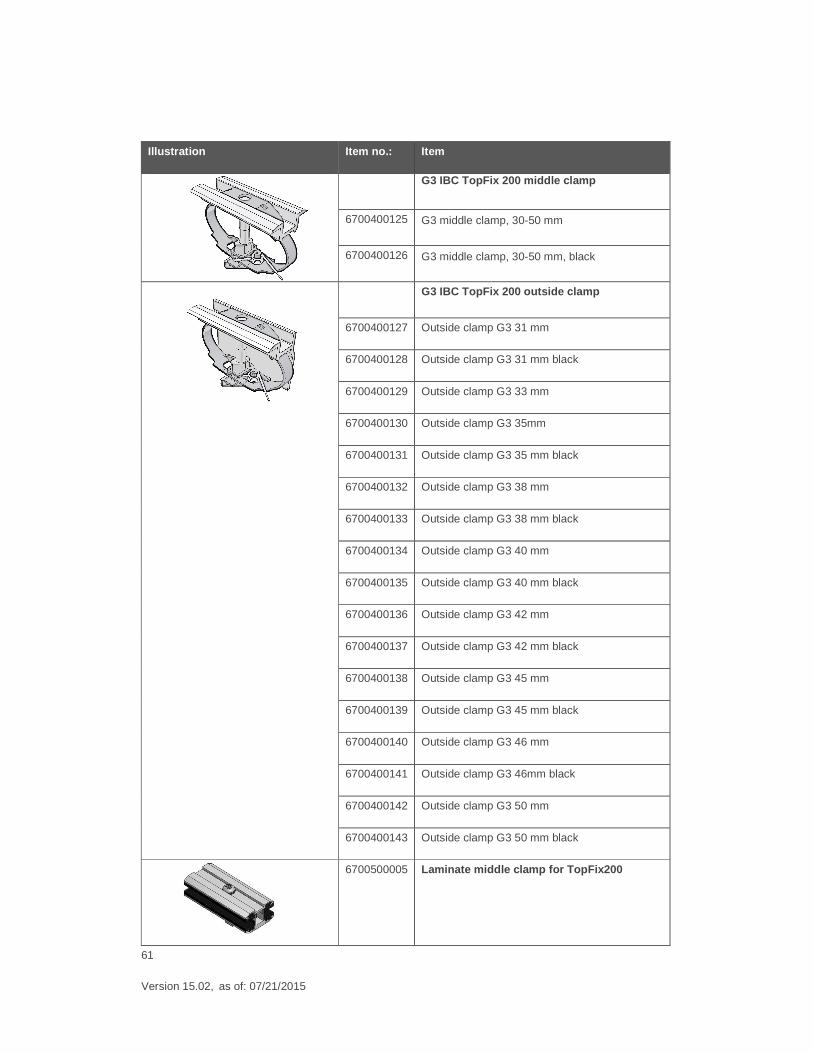
Illustration Item no.: Item
G3 IBC TopFix 200 middle clamp
6700400125 G3 middle clamp, 30-50 mm
6700400126 G3 middle clamp, 30-50 mm, black
G3 IBC TopFix 200 outside clamp
6700400127 Outside clamp G3 31 mm
6700400128 Outside clamp G3 31 mm black
6700400129 Outside clamp G3 33 mm
6700400130 Outside clamp G3 35mm
6700400131 Outside clamp G3 35 mm black
6700400132 Outside clamp G3 38 mm
6700400133 Outside clamp G3 38 mm black
6700400134 Outside clamp G3 40 mm
6700400135 Outside clamp G3 40 mm black
6700400136 Outside clamp G3 42 mm
6700400137 Outside clamp G3 42 mm black
6700400138 Outside clamp G3 45 mm
6700400139 Outside clamp G3 45 mm black
6700400140 Outside clamp G3 46 mm
6700400141 Outside clamp G3 46mm black
6700400142 Outside clamp G3 50 mm
6700400143 Outside clamp G3 50 mm black
6700500005 Laminate middle clamp for TopFix200
62
Version 15.02, as of: 07/21/2015
Illustration Item no.: Item
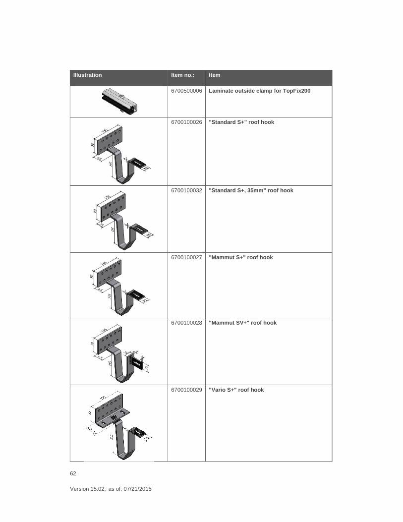
6700500006
Laminate outside clamp for TopFix200
6700100026 "Standard S+" roof hook
6700100032 "Standard S+, 35mm" roof hook
6700100027 "Mammut S+" roof hook
6700100028 "Mammut SV+" roof hook
6700100029 "Vario S+" roof hook
63
Version 15.02, as of: 07/21/2015
Illustration Item no.: Item
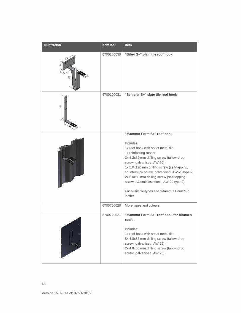
6700100030 "Biber S+" plain tile roof hook
6700100031 "Schiefer S+" slate tile roof hook
"Mammut Form S+" roof hook
Includes: 1x roof hook with sheet metal tile
1x reinforcing runner
3x 4.2x32 mm drilling screw (tallow-drop
screw, galvanised, AW 20) 1x 5.0x120 mm drilling screw (self-tapping,
countersunk screw, galvanised, AW 20 type 2) 2x 5.0x60 mm drilling screw (self-tapping
screw, A2 stainless steel, AW 20 type 2)
For available types see "Mammut Form S+"
leaflet
6700700020 More types and colours
6700700021 "Mammut Form S+" roof hook for bitumen roofs
Includes:
1x roof hook with sheet metal tile 8x 4.8x32 mm drilling screw (tallow-drop
screw, galvanised, AW 25) 2x 4.8x60 mm drilling screw (tallow-drop
screw, galvanised, AW 25)
64
Version 15.02, as of: 07/21/2015
Illustration Item no.: Item
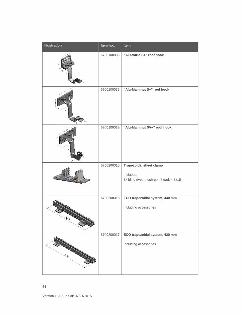
6700100036 “Alu-Vario S+” roof hook
6700100038 “Alu-Mammut S+” roof hook
6700100039 “Alu-Mammut SV+” roof hook
6700200015 Trapezoidal sheet clamp
Includes:
3x blind rivet, mushroom head, 4.8x15
6700200016 ECO trapezoidal system, 340 mm
Including accessories
6700200017 ECO trapezoidal system, 420 mm
Including accessories
65
Version 15.02, as of: 07/21/2015
Illustration Item no.: Item
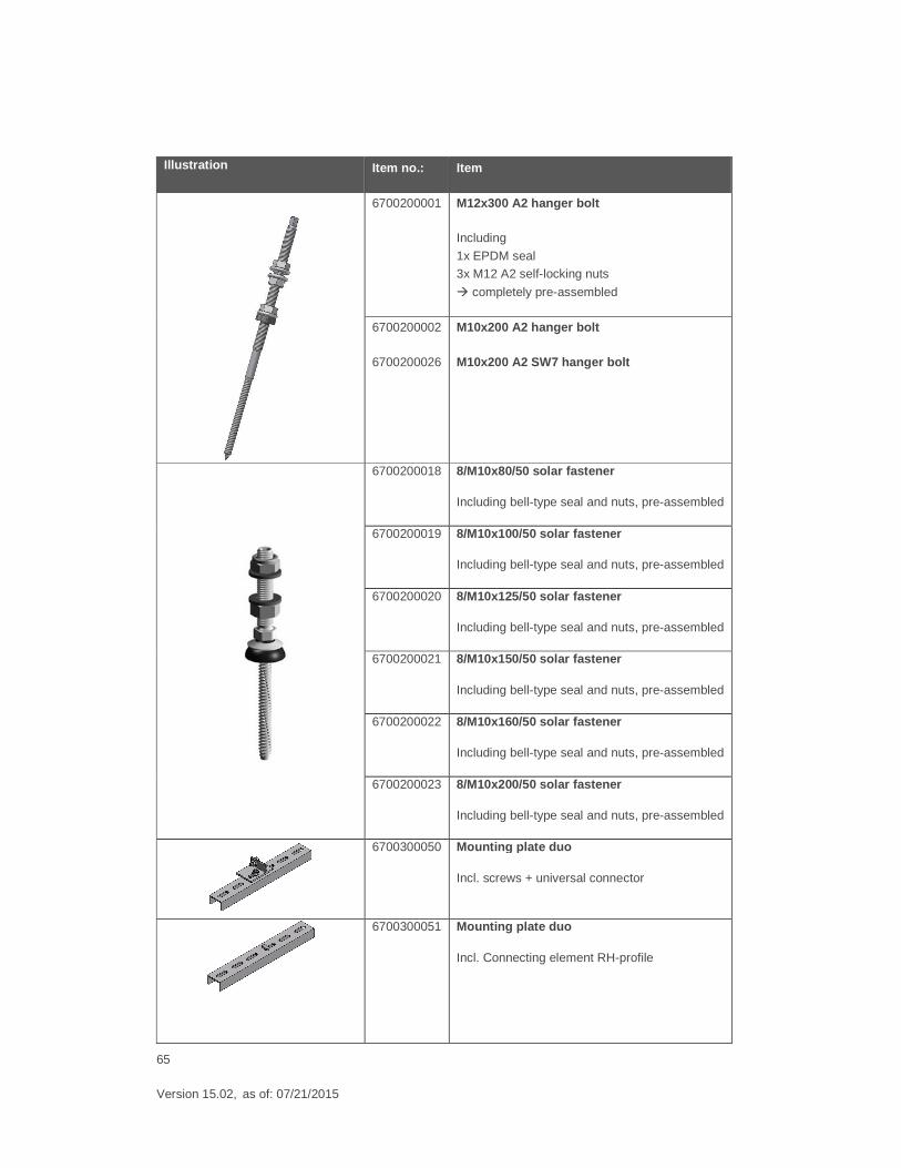
6700200001 M12x300 A2 hanger bolt
Including
1x EPDM seal 3x M12 A2 self-locking nuts
� completely pre-assembled
6700200002
6700200026
M10x200 A2 hanger bolt
M10x200 A2 SW7 hanger bolt
6700200018 8/M10x80/50 solar fastener
Including bell-type seal and nuts, pre-assembled
6700200019 8/M10x100/50 solar fastener
Including bell-type seal and nuts, pre-assembled
6700200020 8/M10x125/50 solar fastener
Including bell-type seal and nuts, pre-assembled
6700200021 8/M10x150/50 solar fastener
Including bell-type seal and nuts, pre-assembled
6700200022 8/M10x160/50 solar fastener
Including bell-type seal and nuts, pre-assembled
6700200023 8/M10x200/50 solar fastener
Including bell-type seal and nuts, pre-assembled
6700300050 Mounting plate duo
Incl. screws + universal connector
6700300051 Mounting plate duo
Incl. Connecting element RH-profile
66
Version 15.02, as of: 07/21/2015
Illustration Item no.: Item
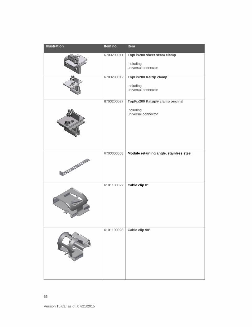
6700200011 TopFix200 sheet seam clamp
Including universal connector
6700200012 TopFix200 Kalzip clamp
Including universal connector
6700200027 TopFix200 Kalzip ® clamp original
Including universal connector
6700300003 Module retaining angle, stainless steel
6101100027 Cable clip 0°
6101100028 Cable clip 90°
67
Version 15.02, as of: 07/21/2015
Illustration Item no.: Item
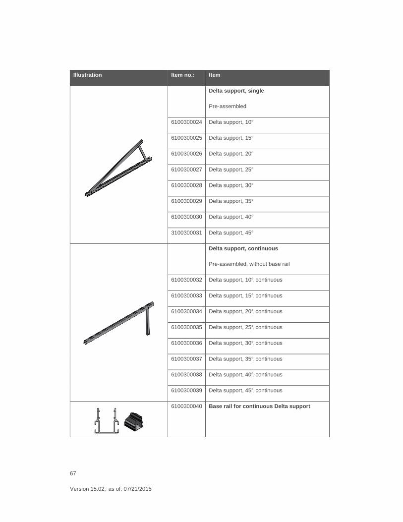
Delta support, single
Pre-assembled
6100300024 Delta support, 10°
6100300025 Delta support, 15°
6100300026 Delta support, 20°
6100300027 Delta support, 25°
6100300028 Delta support, 30°
6100300029 Delta support, 35°
6100300030 Delta support, 40°
3100300031 Delta support, 45°
Delta support, continuous
Pre-assembled, without base rail
6100300032 Delta support, 10°, continuous
6100300033 Delta support, 15°, continuous
6100300034 Delta support, 20°, continuous
6100300035 Delta support, 25°, continuous
6100300036 Delta support, 30°, continuous
6100300037 Delta support, 35°, continuous
6100300038 Delta support, 40°, continuous
6100300039 Delta support, 45°, continuous
6100300040 Base rail for continuous Delta support
68
Version 15.02, as of: 07/21/2015
Illustration Item no.: Item
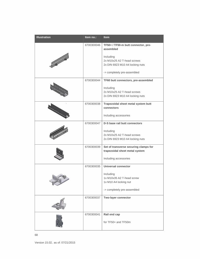
6700300046 TF50+ / TF50-m butt connector, pre-assembled
Including 2x M10x25 A2 T-head screws
2x DIN 6923 M10 A4 locking nuts
-> completely pre-assembled
6700300044 TF60 butt connectors, pre-assembled
Including
2x M10x25 A2 T-head screws
2x DIN 6923 M10 A4 locking nuts
6700300038 Trapezoidal sheet metal system butt connectors
Including accessories
6700300047 D-S base rail butt connectors
Including 2x M10x25 A2 T-head screws
2x DIN 6923 M10 A4 locking nuts
6700300039 Set of transverse securing clamps for trapezoidal sheet metal system
Including accessories
6700300035 Universal connector
Including
1x M10x35 A2 T-head screw
1x M10 A4 locking nut
-> completely pre-assembled
6700300037 Two-layer connector
6700300041 Rail end cap
for TF50+ and TF50m
69
Version 15.02, as of: 07/21/2015
Illustration Item no.: Item
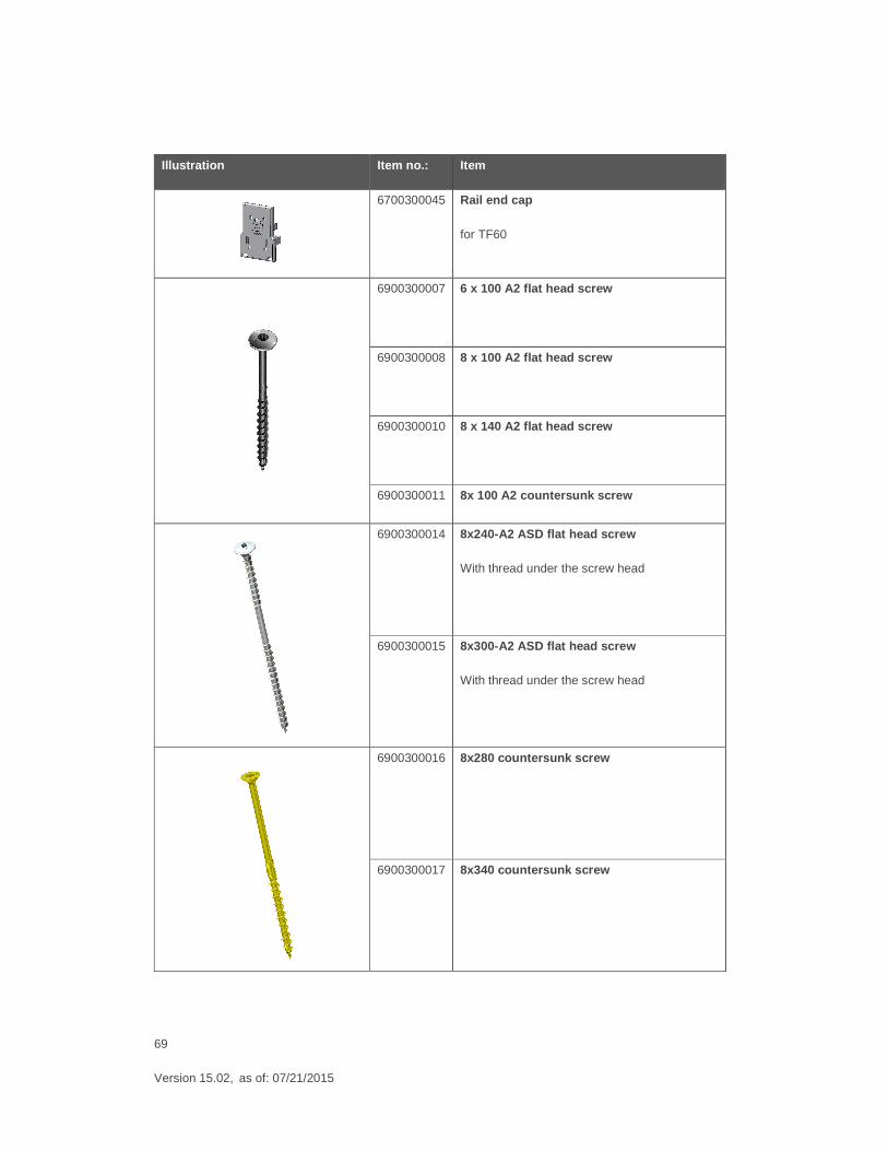
6700300045 Rail end cap
for TF60
6900300007 6 x 100 A2 flat head screw
6900300008 8 x 100 A2 flat head screw
6900300010 8 x 140 A2 flat head screw
6900300011 8x 100 A2 countersunk screw
6900300014 8x240-A2 ASD flat head screw
With thread under the screw head
6900300015 8x300-A2 ASD flat head screw
With thread under the screw head
6900300016 8x280 countersunk screw
6900300017 8x340 countersunk screw
70
Version 15.02, as of: 07/21/2015
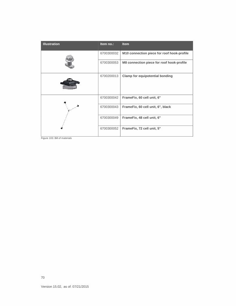
Illustration Item no.: Item
6700300032 M10 connection piece for roof hook-profile
6700300053 M8 connection piece for roof hook-profile
6700200013 Clamp for equipotential bonding
6700300042 FrameFix, 60 cell unit, 6"
6700300043 FrameFix, 60 cell unit, 6", black
6700300049 FrameFix, 48 cell unit, 6"
6700300052 FrameFix, 72 cell unit, 5"
Figure 103: Bill of materials
71
Version 15.02, as of: 07/21/2015
12. Appendix
12.1 Notes on IBC TopFix 200
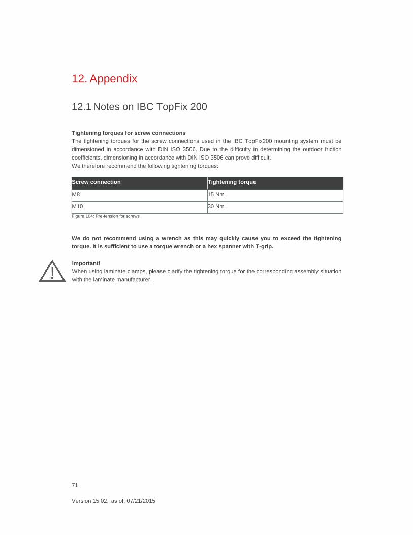
Tightening torques for screw connections The tightening torques for the screw connections used in the IBC TopFix200 mounting system must be
dimensioned in accordance with DIN ISO 3506. Due to the difficulty in determining the outdoor friction coefficients, dimensioning in accordance with DIN ISO 3506 can prove difficult.
We therefore recommend the following tightening torques:
Screw connection Tightening torque
M8 15 Nm
M10 30 Nm Figure 104: Pre-tension for screws
We do not recommend using a wrench as this may quickly cause you to exceed the tighten ing torque. It is sufficient to use a torque wrench or a hex sp anner with T-grip.
Important! When using laminate clamps, please clarify the tightening torque for the corresponding assembly situation
with the laminate manufacturer.
72
Version 15.02, as of: 07/21/2015
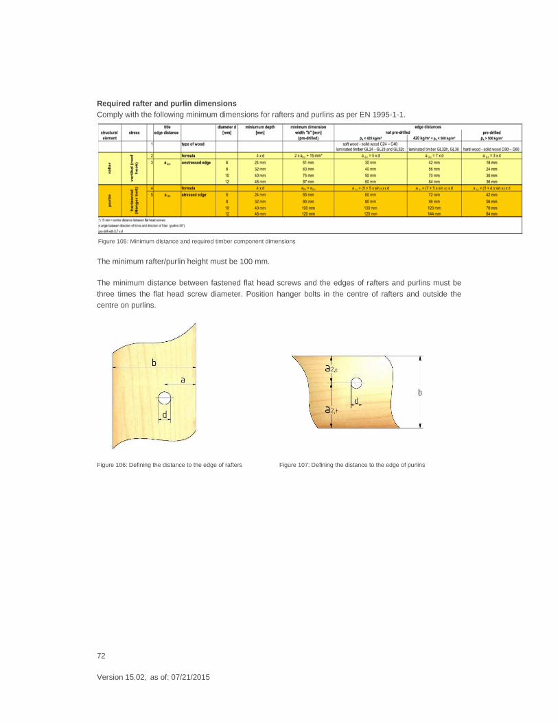
Required rafter and purlin dimensions Comply with the following minimum dimensions for rafters and purlins as per EN 1995-1-1.
The minimum rafter/purlin height must be 100 mm.
The minimum distance between fastened flat head screws and the edges of rafters and purlins must be
three times the flat head screw diameter. Position hanger bolts in the centre of rafters and outside the
centre on purlins.
Figure 106: Defining the distance to the edge of rafters Figure 107: Defining the distance to the edge of purlins
Figure 105: Minimum distance and required timber component dimensions
73
Version 15.02, as of: 07/21/2015
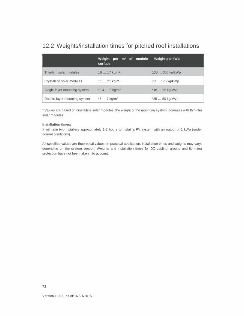
12.2 Weights/installation times for pitched roof installations
Weight per m² of module surface
Weight per kWp
Thin-film solar modules 10 … 17 kg/m² 130 … 300 kg/kWp
Crystalline solar modules 11 … 21 kg/m² 70 … 175 kg/kWp
Single-layer mounting system *2.4 … 5 kg/m² *18 … 35 kg/kWp
Double-layer mounting system *5 … 7 kg/m² *35 … 50 kg/kWp
* Values are based on crystalline solar modules, the weight of the mounting system increases with thin-film
solar modules.
Installation times: It will take two installers approximately 1-2 hours to install a PV system with an output of 1 kWp (under normal conditions).
All specified values are theoretical values. In practical application, installation times and weights may vary,
depending on the system version. Weights and installation times for DC cabling, ground and lightning
protection have not been taken into account.
74
Version 15.02, as of: 07/21/2015
12.3 Notes on maintenance
The IBC TopFix 200 mounting system is largely maintenance-free thanks to the materials used.
In addition to the electrical inspections prescribed for the entire PV system, we recommend inspections of the PV generator every two years, considering the following points.
Check: � Solar modules for damage and dirt
� All mechanical connections are firmly secured (re-tightening screw connections)
� Mounting system and module frame for mechanical damage caused by snow and ice loads
� Integrity of the outer roofing
� All electrical cables for damage (e.g. by animals)
� All electrical plug and screw connections are secure and protected against accidental contact
If it becomes necessary to clean the modules, this must be done without chemical cleaning products and using clear water only.
The modules can easily be replaced by removing the module cabling and undoing the corresponding module clamps. In this process, please observe the relevant safety requirements.
75
Version 15.02, as of: 07/21/2015
IBC SOLAR AG
Am Hochgericht 10
D-96231 Bad Staffelstein
Phone +49 (0) 9573-92 24 0
Fax +49 (0) 9573-92 24 111
www.ibc-solar.com


