TM PC5936 v1.O WARNING This manual contains information on limitations regarding product use and function and information on the limitations as to liability of the manufacturer. The entire manual should be carefully read. Installation Manual
Transcript
TM PC5936 v1.O
WARNINGThis manual contains information on limitations regarding product use
and function and information on the limitations as to liability of the manufacturer. The entire manual should be carefully read.
Section 2:Getting Started 32.1 Installation Steps ...........................................................................32.2 Keybus Wiring ...............................................................................42.3 Audio Link Connection.................................................................42.4 Audio Station Wiring ...................................................................52.5 Telephone Line Connection .........................................................62.6 Music Input Wiring ......................................................................6
Section 3:Audio Functions 73.1 Paging .............................................................................................73.2 Page Listens To All .......................................................................73.3 Cancelling a Page ..........................................................................73.4 Do Not Disturb ..............................................................................73.5 Answering Doorbells ....................................................................83.6 Opening the Door .........................................................................83.7 Doorchime ......................................................................................83.8 Monitoring .....................................................................................83.9 Answering Incoming Calls ..........................................................93.10 Transferring and Holding Calls ..................................................93.11 Call Waiting ...................................................................................93.12 User Help (Keypad function key) ...............................................93.13 Music Input ..................................................................................103.14 Alarm Follower ...........................................................................103.15 Verbal Alarm Announcements .................................................103.16 Central Station Talk/Listen-in ...................................................11
Section 4:Installer Programmable Features & Options 124.1 Port Definitions ...........................................................................124.2 Zone Assignment ........................................................................124.3 Keypad Assignment ...................................................................134.4 Broadcast Mask ...........................................................................134.5 Audio Options .............................................................................134.6 Audio Duration ...........................................................................144.7 Phone Key Options .....................................................................144.8 Listen-In Options ........................................................................154.9 Telephone Ring Options ............................................................164.10 Music Broadcast Mask ...............................................................164.11 Port Function Key .......................................................................164.12 Function Key ................................................................................16
Section 5:Programming Worksheets 17
WARNING Please Read CarefullyNote to InstallersThis warning contains vital information. As the only individualin contact with system users, it is your responsibility to bringeach item in this warning to the attention of the users of this sys-tem.System FailuresThis system has been carefully designed to be as effective aspossible. There are circumstances, however, involving fire, bur-glary, or other types of emergencies where it may not provideprotection. Any alarm system of any type may be compromiseddeliberately or may fail to operate as expected for a variety ofreasons. Some but not all of these reasons may be:· Inadequate InstallationA security system must be installed properly in order to provideadequate protection. Every installation should be evaluated by asecurity professional to ensure that all access points and areasare covered. Locks and latches on windows and doors must besecure and operate as intended. Windows, doors, walls, ceilingsand other building materials must be of sufficient strength andconstruction to provide the level of protection expected. Areevaluation must be done during and after any constructionactivity. An evaluation by the fire and/or police department ishighly recommended if this service is available.· Criminal KnowledgeThis system contains security features which were known to beeffective at the time of manufacture. It is possible for personswith criminal intent to develop techniques which reduce theeffectiveness of these features. It is important that a security sys-tem be reviewed periodically to ensure that its features remaineffective and that it be updated or replaced if it is found that itdoes not provide the protection expected.· Access by IntrudersIntruders may enter through an unprotected access point, cir-cumvent a sensing device, evade detection by moving throughan area of insufficient coverage, disconnect a warning device, orinterfere with or prevent the proper operation of the system.· Power FailureControl units, intrusion detectors, smoke detectors and manyother security devices require an adequate power supply forproper operation. If a device operates from batteries, it is possi-ble for the batteries to fail. Even if the batteries have not failed,they must be charged, in good condition and installed correctly.If a device operates only by AC power, any interruption, how-ever brief, will render that device inoperative while it does nothave power. Power interruptions of any length are often accom-panied by voltage fluctuations which may damage electronicequipment such as a security system. After a power interruptionhas occurred, immediately conduct a complete system test toensure that the system operates as intended.· Failure of Replaceable BatteriesThis system’s wireless transmitters have been designed to pro-vide several years of battery life under normal conditions. Theexpected battery life is a function of the device environment,usage and type. Ambient conditions such as high humidity, highor low temperatures, or large temperature fluctuations mayreduce the expected battery life. While each transmitting devicehas a low battery monitor which identifies when the batteriesneed to be replaced, this monitor may fail to operate as expected.Regular testing and maintenance will keep the system in goodoperating condition.· Compromise of Radio Frequency (Wire-less) DevicesSignals may not reach the receiver under all circumstanceswhich could include metal objects placed on or near the radiopath or deliberate jamming or other inadvertent radio signalinterference.· System UsersA user may not be able to operate a panic or emergency switchpossibly due to permanent or temporary physical disability,inability to reach the device in time, or unfamiliarity with thecorrect operation. It is important that all system users be trainedin the correct operation of the alarm system and that they knowhow to respond when the system indicates an alarm.· Smoke DetectorsSmoke detectors that are a part of this system may not properlyalert occupants of a fire for a number of reasons, some of whichfollow. The smoke detectors may have been improperly
installed or positioned. Smoke may not be able to reach thesmoke detectors, such as when the fire is in a chimney, walls orroofs, or on the other side of closed doors. Smoke detectors maynot detect smoke from fires on another level of the residence orbuilding.Every fire is different in the amount of smoke produced and therate of burning. Smoke detectors cannot sense all types of firesequally well. Smoke detectors may not provide timely warningof fires caused by carelessness or safety hazards such as smok-ing in bed, violent explosions, escaping gas, improper storage offlammable materials, overloaded electrical circuits, childrenplaying with matches or arson.Even if the smoke detector operates as intended, there may becircumstances when there is insufficient warning to allow alloccupants to escape in time to avoid injury or death.· Motion DetectorsMotion detectors can only detect motion within the designatedareas as shown in their respective installation instructions. Theycannot discriminate between intruders and intended occupants.Motion detectors do not provide volumetric area protection.They have multiple beams of detection and motion can only bedetected in unobstructed areas covered by these beams. Theycannot detect motion which occurs behind walls, ceilings, floor,closed doors, glass partitions, glass doors or windows. Any typeof tampering whether intentional or unintentional such as mask-ing, painting, or spraying of any material on the lenses, mirrors,windows or any other part of the detection system will impair itsproper operation.Passive infrared motion detectors operate by sensing changes intemperature. However their effectiveness can be reduced whenthe ambient temperature rises near or above body temperature orif there are intentional or unintentional sources of heat in or nearthe detection area. Some of these heat sources could be heaters,radiators, stoves, barbeques, fireplaces, sunlight, steam vents,lighting and so on.· Warning Devices Warning devices such as sirens, bells, horns, or strobes may notwarn people or waken someone sleeping if there is an interven-ing wall or door. If warning devices are located on a differentlevel of the residence or premise, then it is less likely that theoccupants will be alerted or awakened. Audible warning devicesmay be interfered with by other noise sources such as stereos,radios, televisions, air conditioners or other appliances, or pass-ing traffic. Audible warning devices, however loud, may not beheard by a hearing-impaired person.· Telephone LinesIf telephone lines are used to transmit alarms, they may be out ofservice or busy for certain periods of time. Also an intruder maycut the telephone line or defeat its operation by more sophisti-cated means which may be difficult to detect.· Insufficient TimeThere may be circumstances when the system will operate asintended, yet the occupants will not be protected from the emer-gency due to their inability to respond to the warnings in atimely manner. If the system is monitored, the response may notoccur in time to protect the occupants or their belongings.· Component FailureAlthough every effort has been made to make this system asreliable as possible, the system may fail to function as intendeddue to the failure of a component.· Inadequate TestingMost problems that would prevent an alarm system from operat-ing as intended can be found by regular testing and maintenance.The complete system should be tested weekly and immediatelyafter a break-in, an attempted break-in, a fire, a storm, an earth-quake, an accident, or any kind of construction activity inside oroutside the premises. The testing should include all sensingdevices, keypads, consoles, alarm indicating devices and anyother operational devices that are part of the system.· Security and InsuranceRegardless of its capabilities, an alarm system is not a substitutefor property or life insurance. An alarm system also is not a sub-stitute for property owners, renters, or other occupants to actprudently to prevent or minimize the harmful effects of an emer-gency situation.
1
Section 1: Introduction
1.1 SpecificationsIt is recommended that a 7 Amp hour battery (minimum) be usedon the PC5020/P-8+ when the PC5936 is used.
NOTE: In order for the PC5936 module to operate properly, thepower output capability from the AUX terminals combined mustnot be exceeded. Use the data presented below to ensure that thePC5936 module is not overloaded when connecting audio stations.
Compatible PanelsDSC PartnerPC5008 v2.1 and higherPC5010 v2.0 P-832 v2.0PC5015 v2.2 and higher P-832DL v2.2 and higherPC5020 v3.0 and higher P-8+ v3.0 and higher
NOTE: The Verbal Door Chime and Verbal Alarm feature is onlyavailable when using the PC5020/P-8+ v3.1.
PC5936 Audio Interface Module• Standby current draw - 65 mA• Maximum current draw - 100 mA• Total current - providing capability between AUX terminals -
500 mA• Input impedance at any microphone input - 25kΩ• Maximum music input signal level amplitude - 200mV peak to
peak• Connect up to 7 audio stations (interior or exterior)• Page function• Monitor function• Answer incoming calls• Alarm output follower
PC5937 Eight-port Expansion Module• Current draw - 5 mA• Connect up to 8 audio stations (interior or exterior)• Total current - providing capability between AUX terminals -
500 mA• Input impedance at any microphone input - 25kΩ• Maximum music input signal level amplitude - 200 mV peak
to peak
PC5921 Interior Audio Station (Partner model P5922)• Standby current draw - 20 mA• Maximum current draw - 50 mA• Built-in speaker and microphone
PC5921EXT Exterior Audio Station (Partner model P5922EXT)• Standby current draw - 20 mA• Maximum current draw - 50 mA• Built-in speaker and microphone
2
PC5921EXT/R Exterior Audio Station (Partner model P5922 EXT/R)• Standby current draw - 20 mA• Maximum current draw - 50 mA• Built-in speaker and microphone• Relay output for doorbell circuit connection
PC5904 Central Station Talk/Listen Module• Standby current draw - 30 mA• Maximum current draw - 175 mA• Built in microphone and 3.5 in. speaker
1.2 Additional DevicesPC5937 Eight Port Expansion Module
The PC5937 adds 8 more ports to the PC5936 Audio Interfacemodule.
PC5921 Interior Audio StationEach station has a separate microphone and speaker. Each stationmust be home run to the interface module using shielded 22gauge, 4 conductor wire. Each station can be used to initiate orreceive pages, answer incoming calls, answer the doorbell, moni-tor rooms or sound an alarm follower.
PC5921EXT Exterior Audio Station (Partner model P5922EXT)The PC5921/P5922EXT exterior audio station is housed in a grayfade-resistant case, designed for outside use. Each station has aseparate microphone and speaker. Each station must be home runto the interface module using shielded 22 gauge, 4 conductor wire.The station can be used to sound the doorbell chime on interioraudio stations.
PC5921EXT/R Exterior Audio Station (Partner model P5922EXT/R)The PC5921/P5922EXT/R exterior audio station is housed in agray fade-resistant case, designed for outside use. Each station hasa separate microphone and speaker. Each station must be homerun to the interface module using shielded 22 gauge, 4 conductorwire. The station can be used to sound the doorbell chime on inte-rior audio stations. A relay is included so that a pre-existing door-bell can be used.
PC5904 Central Station Talk/Listen ModuleThe PC5904 interior central station talk listen module is used inconjunction with the PC5936 audio interface module for talk/lis-ten-in purposes. While all other station types can provide talk/lis-ten-in capabilities, this station provides an added level of volumeto the central station operator’s voice. Each station has a separatemicrophone and speaker. Each station must be home run to theinterface module using shielded 22 gauge, 4 conductor wire. Allstations can be used to sound an alarm follower.
NOTE: EXT audio stations should always be shielded wheninstalled in harsh environments.
3
Section 2: Gett ing Started
2.1 Installation StepsFollow these steps to install the PC5936 audio interface moduleand audio stations. Review this section to get an overall under-standing of the order of installation. Once this is done, carefullywork through each step.
Step 1 Mounting the PC5936 Audio Interface ModuleMount the cabinet close to the control panel as the PC5936 mustbe connected to the incoming telephone line. Before attaching thecabinet to the wall make sure to press the nylon circuit boardmounting studs into the cabinet from the back.
Step 2 Connecting the PC5937 Module (optional)To add 8 ports to the system, connect the PC5937 to the PC5936module. See the PC5937 Installation Sheet for instructions.
Step 3 Wiring the KeybusWire the Keybus to the PC5936 audio interface module accordingto the diagram provided in 2.2 “Keybus Wiring” on page 4.
Step 4 Wiring the Audio StationsWire each audio station according to the diagram provided in 2.4“Audio Station Wiring” on page 5.
Step 5 Wiring the Incoming Telephone LineWire the incoming telephone line according to the diagram pro-vided in 2.5 “Telephone Line Connection” on page 6.
Step 6 Supervision of the PC5936The PC5936 will function upon power-up; however, full supervi-sion of the module must be enabled in the panel (PC5020/P-8+).
Step 7 Program the PanelThe PC5936 audio interface module programming can be donefrom any PowerSeries keypad. Refer to the Audio Interface Pro-gramming Worksheets for program items and options.
Helpful Installation Tips
FeedbackIf an intercom station appears to be exhibiting feedback noise,check the following for potential causes.
• Microphone - Remove the backplate. The microphone andholder are located in the bottom-left corner. Ensure that themicrophone is pushed fully into the black rubber holder so thatthe face of it is flat against the rubber.
• Speaker - Ensure that the felt is secured around the speaker.
4
• Gain Control - Remove the backplate. The speaker volumecontrol is located directly above the microphone and themicrophone sensitivity control is located directly beneath thespeaker. Turning either of these controls counter clockwisewill reduce their gain, thereby reducing the possible level offeedback.
• Placement - Avoid installing intercom stations directly acrossfrom one another. Feedback may also occur due to roomacoustics which will be affected by several different factorssuch as the size of the room, whether or not the floor is car-peted and different objects that may be in the room. Try mov-ing one of the intercom stations to correct the problem.
• Ventilation - In some extreme instances the station may befeeding back to itself. The speaker output may be feeding backinto the microphone within the housing. To eliminate this,open a hole through the wall equal in size to the rectangularopening in the backplate to allow the sound to escape.
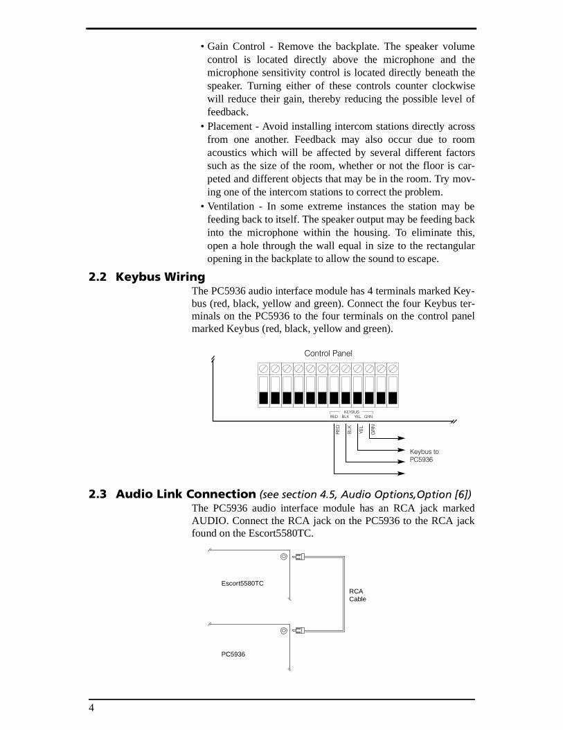
2.2 Keybus WiringThe PC5936 audio interface module has 4 terminals marked Key-bus (red, black, yellow and green). Connect the four Keybus ter-minals on the PC5936 to the four terminals on the control panelmarked Keybus (red, black, yellow and green).
2.3 Audio Link Connection (see section 4.5, Audio Options,Option [6])The PC5936 audio interface module has an RCA jack markedAUDIO. Connect the RCA jack on the PC5936 to the RCA jackfound on the Escort5580TC.
Escort5580TC
PC5936
RCACable
5
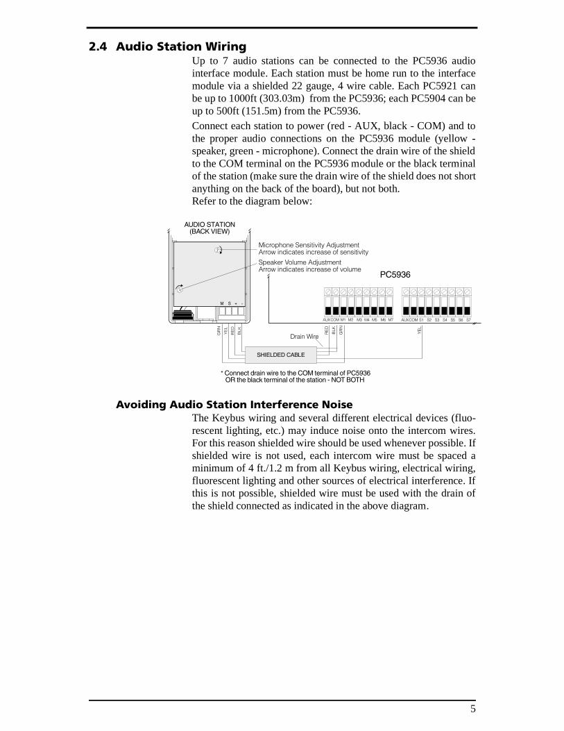
2.4 Audio Station WiringUp to 7 audio stations can be connected to the PC5936 audiointerface module. Each station must be home run to the interfacemodule via a shielded 22 gauge, 4 wire cable. Each PC5921 canbe up to 1000ft (303.03m) from the PC5936; each PC5904 can beup to 500ft (151.5m) from the PC5936. Connect each station to power (red - AUX, black - COM) and tothe proper audio connections on the PC5936 module (yellow -speaker, green - microphone). Connect the drain wire of the shieldto the COM terminal on the PC5936 module or the black terminalof the station (make sure the drain wire of the shield does not shortanything on the back of the board), but not both. Refer to the diagram below:
Avoiding Audio Station Interference NoiseThe Keybus wiring and several different electrical devices (fluo-rescent lighting, etc.) may induce noise onto the intercom wires.For this reason shielded wire should be used whenever possible. Ifshielded wire is not used, each intercom wire must be spaced aminimum of 4 ft./1.2 m from all Keybus wiring, electrical wiring,fluorescent lighting and other sources of electrical interference. Ifthis is not possible, shielded wire must be used with the drain ofthe shield connected as indicated in the above diagram.
6
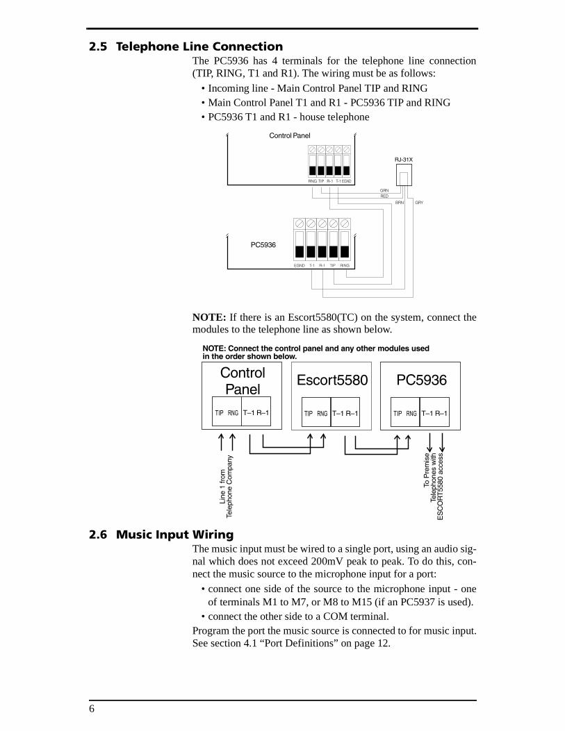
2.5 Telephone Line ConnectionThe PC5936 has 4 terminals for the telephone line connection(TIP, RING, T1 and R1). The wiring must be as follows:
• Incoming line - Main Control Panel TIP and RING• Main Control Panel T1 and R1 - PC5936 TIP and RING• PC5936 T1 and R1 - house telephone
NOTE: If there is an Escort5580(TC) on the system, connect themodules to the telephone line as shown below.
2.6 Music Input WiringThe music input must be wired to a single port, using an audio sig-nal which does not exceed 200mV peak to peak. To do this, con-nect the music source to the microphone input for a port:
• connect one side of the source to the microphone input - oneof terminals M1 to M7, or M8 to M15 (if an PC5937 is used).
• connect the other side to a COM terminal. Program the port the music source is connected to for music input.See section 4.1 “Port Definitions” on page 12.
7
Section 3: Audio Functions
3.1 PagingUsers can page people on the premises using the intercom stations.
NOTE: Only one page can be performed at a time.To initiate a page press the Page/Answer button on any station.The station beeps twice. If no beeps are heard it is because anotherconversation is already taking place. If the page is successful allother stations that are not on “Do Not Disturb” will sound a rapidbeep. Talk into the audio station. The system broadcasts yourvoice to all other interior audio stations.To answer the page, press the Page/Answer button on another sta-tion. The station beeps twice to indicate that a connection is estab-lished between the intercom stations where the page was initiatedand answered. No other station will transmit the conversation.The PC5936 automatically detects the source of the loudest voiceand uses this to control the direction of conversation. During apage, the Do Not Disturb (DND) light will be on when the micro-phone of the intercom station is active.To end a page, either person can press the Page/Answer button. Ifthe PC5936 detects silence for 30 seconds, it will end the page.
3.2 Page Listens To AllYou can program the system so that when a page is initiated, usersat all other intercom stations can respond “handsfree” for 30 sec-onds (i.e. without pressing the Page/Answer button). Ports inDND mode, or which have the Paging/Monitoring/DoorbellSounds option turned off will not be able to answer the page.
A user who wants to talk for longer than 30 seconds can press thePage/Answer button to establish a private communication link. Ifthe page is not answered within 30 seconds, it will time out.
3.3 Cancelling a PageTo cancel a page, press the Page/Answer button a second time.The page will automatically be cancelled if there is no response in30 seconds.
3.4 Do Not DisturbTo avoid receiving pages, doorbox exterior intercom station callsor incoming telephone calls, users can put a station on Do NotDisturb (DND). To do this, press the Do Not Disturb button on thestation. The Do Not Disturb light on the station will come on toindicate the unit is in Do Not Disturb mode.
To take a station off DND, press the Do Not Disturb button again.The Do Not Disturb light on the station will go out.
8
3.5 Answering DoorbellsExterior stations (PC5921/P5922EXT, PC5921/P5922EXT/R) canbe programmed as doorbox 1 or doorbox 2 for doorbell operation.When someone presses the button on a doorbox 1 station, it willbroadcast a “dingdong” sound over the system. Doorbox 2 willbroadcast a “dong” sound over the system.To answer the doorbell users can press the Page/Answer button onany station. The audio channel will operate the same as it does fora page.If a page is in progress when a doorbell is pressed the two personson the page will hear the tone. To answer the doorbell either per-son can press the Page/Answer button. The page will end and theuser will immediately be connected to the doorbell station.
3.6 Opening the DoorYou can program any intercom station to open the door (using adoorstrike module) while in communication with a doorbox station.After answering a doorbell on an intercom station, press and holdthe Page/Answer button for 2 seconds to activate the doorstrike.The system will sound an acknowledgment beep. The control panelwill trigger the programmed Command Output (1 - 8), which willactivate the PGM output connected to the doorstrike. To terminate communications with the doorbox station, press thePage/Answer button briefly.
3.7 DoorchimeIf the doorchime feature is enabled for zones on the system, when azone is violated or restored, the keypads on the partition will beep.If an Escort5580(TC) v3.0 is connected to the system, it willannounce the label for the zone which generated the doorchimeover the audio stations (NOTE: This feature is only available withthe PC5020/P-8+ v3.1).
3.8 MonitoringThe Monitor feature allows users to listen-in on one area at anyother intercom station (except stations on DND). To listen-in onan area, go to the station in the area and press and hold the Do NotDisturb button for two seconds. The station will be put in Do NotDisturb mode and the Do Not Disturb light will flash. ThePC5936 will transmit all sounds heard from that station to all theother stations on the system.Other features such as paging, door answer and answering incom-ing calls can still be performed and will override the monitor fea-ture. If a page, door answer or telephone call answer is in progressthe monitor feature will not operate until the conversation isended. To turn off the monitor feature press the Do Not Disturbbutton once. The red light on the station will stop flashing.Only one station at a time can be monitored. To monitor anotherarea, turn the monitor feature off on the first station.
9
3.9 Answering Incoming CallsWhen an incoming call is detected, the PC5936 will sound a ring-ing tone on all stations which are enabled to sound the tone(unless on Do Not Disturb). To answer the call the user must pressthe Page/Answer button for 1 second. Once the call is answeredthe audio channel will operate the same as it does for a page.The call will end if the user presses and holds the Page/Answerbutton for 1 second. The call will also end after 30 seconds ofsilence.If a page is in progress when an incoming call is detected only thetwo users on the page will hear the ring. To answer the call eitheruser can press and hold the Page/Answer button for 1 second. Thepage will end and the user will immediately be connected to theincoming call.If a user has answered a telephone call at an intercom station andthen the doorbell is pressed, the user will hear the doorbell. Theuser can press Page/Answer to hang up the telephone, and thenpress Page/Answer one more time to answer the doorbell.
3.10Transferring and Holding CallsOnce a user has answered a call on an intercom station, they can:
• put the call on hold• transfer the call to an in-house telephone• page someone so that they can answer the call at another inter-
com stationTo put a call on hold press the Do Not Disturb button once. Oncethe call is on hold, you can page someone else to answer the call,or answer doorbells as usual.To pick up a holding call at a telephone, go to the telephone, pickup the receiver and press the [#] key for 1 second. This puts thecall through to the telephone and disconnects the intercom stationfrom the conversation.
To pick up a holding call at any intercom station, press the Do NotDisturb button.
3.11Call WaitingIf you have answered the telephone through an audio station and asecond call comes in, the station will ring. To answer the secondcall while on line with the first call, press the Page/Answer button.This puts the first call on hold and answers the second call. Toreturn to the first call press the Page/Answer button again.
3.12User Help (Keypad function key)If programmed, users can press the User Help function key at akeypad to broadcast Escort5580(TC) voice prompts through thenearest intercom station. For function key programming instruc-tions, see your PC5020/P-8+ Installation Manual.
10
3.13Music InputThe music input feature allows users to broadcast backgroundmusic to all stations which are enabled for paging. The music inputfeature can be turned on or off using any keypad on the system.For the music input to work, the incoming audio signal must beconnected to a port which is programmed for music input. See 2.6“Music Input Wiring” on page 6 and 4.1 “Port Definitions” onpage 12 for more information. To turn on the background music, enter user programming[*][6][Master Code] then press [9]. To turn off the music, enter[*][6][Master Code][9] again.
NOTE: The monitor and music input feature cannot be on at thesame time. If both are turned on monitoring will take priority andthe music will not be heard.
3.14Alarm FollowerThe audio stations will sound alarm conditions along with the BellOutput of the control panel. All stations will sound an alarm usingBurglary and Fire type tones. All Burglary alarms will sound asteady alarm output. All Fire alarms will sound a pulsed alarmoutput.
3.15Verbal Alarm AnnouncementsIf you have installed an Escort5580TC v3.0 on the system, whenzones go into alarm the Escort will announce the labels for thosezones over the intercom system. The alarm announcement will beas follows:
• an alarm tone• verbal announcement of the first zone in alarm• verbal announcement of the latest zone in alarm• series repeats until alarms are silenced.
NOTE: This feature is only available with the PC5020/P-8+ v3.1.
11
3.16Central Station Talk/Listen-in (Not permitted on UL Listed systems)When a Talk/Listen-in event occurs the PC5936 will seize thetelephone line, call the central station and initiate a talk/listen-insession. The PC5936 will start a 90-second session of low-gainlisten-in on the station closest to the zone in alarm, or on all sta-tions if the CS Listen All option is on (see 4.9 “Telephone RingOptions” on page 16). When the central station operator pressesany key on the telephone a new 90-second session will begin.If a Holdup, Panic or Duress alarm occurs, the operator will onlybe able to listen-in, as the speakers will not be turned on. See 4.9“Telephone Ring Options” on page 16 for information on pro-gramming which events will trigger a talk/listen-in session.Central station operators can control the talk/listen-in sessionusing the keys on their Touch-Tone* telephone. You can programthe functions of these keys by following the instructions in 4.7“Phone Key Options” on page 14.
NOTE: Doorbells and monitoring will not work when talk/listen-inmode is on.
NOTE: If talk/listen-in is active and another event occurs, thePC5936 will end the talk/listen-in session and transmit the eventto the central station.
*Touch-Tone is a trademark of Stentor Resource Centre Inc.
12
Section 4: Installer Program-mable Features & Options
4.1 Port DefinitionsRef: Section [01], Port 1-7Ref: Section [02], Port 8-15
Not Used (Disabled)The port is not connected and is not used. A disabled port has theLED turned ON and does not produce any sound. It does not reactto pushed buttons.
Doorbox 1The port is connected to a speaker/microphone located at anentrance (front door) from which a Page will result in a DoorbellTone (1.72kHz for 600mS, pause for 200uS, 1.3kHz for 600mS)sounding on all interior intercom ports.
Doorbox 2The port is connected to a speaker/microphone located at an alter-nate entrance (back /side door) from which a Page will result in adifferent Doorbell Tone (666Hz for 592mS) sounding on all inte-rior intercom ports.
Intercom (Monitor)The port is connected to any interior speaker/microphone whichcan send or receive pages. This port definition also allows the portto be turned into a monitor station.
Music InputThis port definition allows the port to be turned into a hardwiredmusic input source. When enabled through [*][6] or with a func-tion key, the music input will be broadcasted to all intercom portsenabled for music broadcast (sections 62 and 63).
4.2 Zone AssignmentRef: Section [10], Zones 1-8Ref: Section [11], Zones 9-16Ref: Section [12], Zones 17-24Ref: Section [13], Zones 25-32Ref: Section [14], Zones 33-40Ref: Section [15], Zones 41-48Ref: Section [16], Zones 49-56Ref: Section [17], Zones 57-64Each zone on the system must be assigned to the nearest speaker/microphone intercom for central station talk/listen. Enter 01-15for each zone.
13
4.3 Keypad AssignmentRef: Section [18], Keypad 1-8For use with the User Help function key, this section is used to programwhich audio port/intercom station has been physically placed beside sys-tem keypad. Enter 01-15 for each keypad.
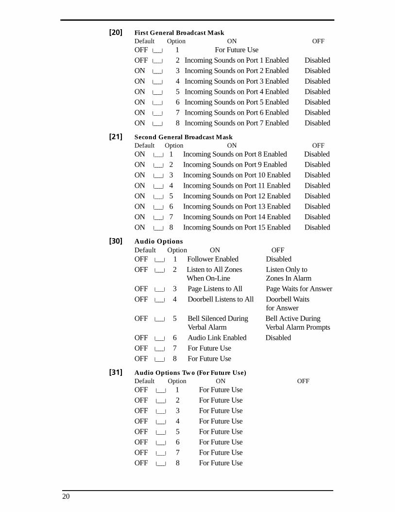
4.4 Broadcast MaskRef: Section [20], Port 1-8Ref: Section [21], Port 9-15Each port can be enabled or disabled for receiving incoming activ-ity on the speaker. When paging to a port/station is disabled in thissection, the DND light will come ON steady. The following sounds are masked off when disabled in this section:
• Incoming pages• Sound from the monitor station• Doorbells
This section does not control the system alarm follower or tele-phone rings.
4.5 Audio OptionsRef: Section [30]
[01] Local Alarm Follower (Default=OFF)ON Alarm tones (burg or fire) will be sounded through the
intercom stations during bell activity.OFF Alarm tones will not be sounded.
[02] Central Station Listen to All (Default=OFF) ON Listen to all zones once on-line. When talk/listen-in is
initiated, the central station will hear activity from allzones until specific zones are selected.
OFF Listen only to zones in alarm once on-line. When talk/listen-in is initiated, the central station will hear activ-ity from only the zones in alarm until specific zones areselected.
[03] Page Listens to All (Default=OFF)
ON Enabling this feature allows all intercom ports torespond to a page without pressing the page/answerbutton to answer (excluding ports in DND or maskedoff in the General Broadcast Options). When a page isinitiated, all other intercom stations can respond to apage without pressing the page/answer button. If thepage is answered on another intercom station, generalpage activity will take place. If the page is notanswered within 30 seconds, it will time out.
OFF Page Waits For Answer. A page must be answered bypressing the Answer button to respond.
14
[04] Doorbell Listens to All (Default=OFF)
ON Handsfree Doorbell. Enabling this feature allows allintercom ports to respond to a Doorbell page withoutpressing the page/answer button to answer (excludingports in DND or masked off in the General BroadcastOptions). When a Doorbell page is initiated, all otherintercom stations can respond to a page without press-ing the page/answer button. If the page is answered onanother intercom station, general page activity willtake place. If the page is not answered within 30 sec-onds, it will time out.
OFF Doorbell Waits For Answer. A page must be answeredby pressing the Answer button to respond
[05] Bells Silenced During Verbal Alarm (Default=OFF)
NOTE: This feature is only available with the PC5020/P-8+ v3.1.ON The Bell will be turned off while annunciating a Verbal
Alarm (only the main panel bell is silenced).OFF The Bell will continue to sound while annunciating a
Verbal Alarm.
NOTE: This feature only affects the main panel bell.
[06] Audio Link Enabled (Default=OFF)
ON The audio link will be used instead of the phone linefor Audio Help and Verbal Prompts.
OFF The phone line will be used for Audio Help and VerbalPrompts.
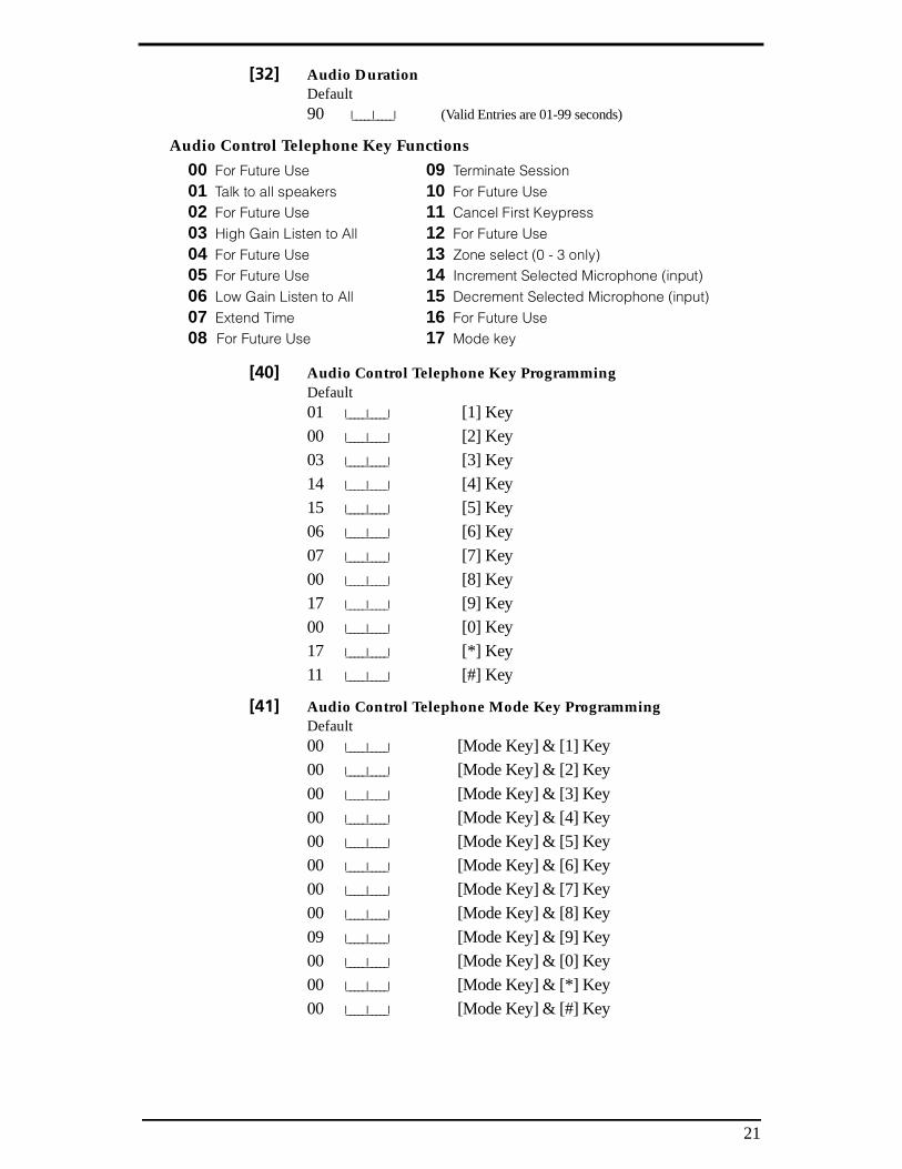
4.6 Audio DurationRef: Section [32] (Default=90)
This section allows programming of the length of time that theAudio Module will remain on-line with the receiver in talk/listen-in. The on-line time can be manually extended by the operator.Valid entries are 00-99 seconds.
4.7 Phone Key OptionsRef: Section [40]Ref: Section [41] Keys [0]-[9], [*] and [#] are programmable for control of the talk/listen-in communication by the central station operator. In addi-tion, a Mode Key can be programmed to add 12 more keys (ModeKey + Key).The available options are as follows:[00] Key Not Used - the key will not perform any function whenpressed during an on-line session.[01] Talk To All Speakers - this key activates high gain talk tothe premises from all speakers.
[02] For Future Use [03] High Gain Listen To All - this key activates high gain listen-in from the premises from all activated microphones.
15
[04] For Future Use[05] For Future Use[06] Low Gain Listen To All - this key activates LOW gain lis-ten-in from the premises from all activated microphones.[07] Extend Time - pressing this key extends the session by thetime programmed in section [55].
[08] For Future Use[09] Terminate Session - when pressed, this key will terminatethe talk/listen-in session. [10] For Future Use[11] Cancel First Keypress - pressing this key will cancel thefirst entry of a 2-digit command (i.e. Zone Select).[12] For Future Use[13] Zone Select - this key requires a 2-digit zone number (01-64) entry after pressing the key. Once the zone number has beenentered the port assigned to that zone is activated for listen-in. Ifthe selected zone does not have a port programmed, the zoneselect function is cancelled (the module returns to the state it wasin before the zone select function key was pressed). [14] Increment Selected Microphone (Input) - if the operatordoes not hear anything initially, they can increment the selectedport by pressing this key.[15] Decrement Selected Microphone (Input) - if the operatordoes not hear anything initially, they can decrement the selectedport by pressing this key.
[16] For Future Use[17] Mode Key - this key allows the operator to toggle to anextended set of commands.
4.8 Listen-In OptionsRef: Section [50] -[57]These toggles are used to enable/disable listen-in for the zonealarms.Ref: Section [58]These toggles are used to enable and disable the system eventswhich will cause the panel to initiate talk/listen-in upon comple-tion of the communication handshake. The following systemevents can be programmed to initiate talk/listen-in.Zone Alarms N (Enable/disable by zone)Tampers NOpenings/Closing N[A] Alarm N[P] Alarm NDuress Alarm NZone Exp. Sup. Alarm NOpen After Alarm N
16
NOTE: The “Terminate Call” key should be used by the operatorbefore hanging up during a talk/listen-in session. The Alarm andtalk/listen options will occur for events from any partition.
4.9 Telephone Ring OptionsRef: Section [60]Ref: Section [61]Each port/intercom station can be enabled or disabled for receiv-ing incoming telephone rings on the speaker.
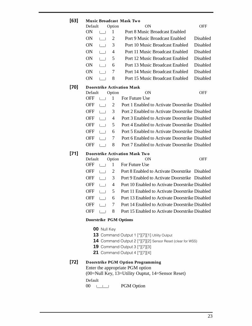
4.10 Music Broadcast MaskRef: Section [62] Port 1-7Ref: Section [63] Port 8-15Each Port/Intercom Station can be enabled/disabled for soundingmusic. Music input needs to be programmed/enabled for this towork.
4.11Port Function KeyRef: Section [70] Port 1-7Ref: Section [71] Port 8-15Each port can be enabled or disabled for activating the doorstrike/function key option while a link is established between an exteriordoorbox station and an interior intercom station.
4.12Function KeyRef: Section [72]This section is used to program which PGM type will be activatedwhen the doorstrike/function key feature is used.
17
Section 5: Programming Worksheets
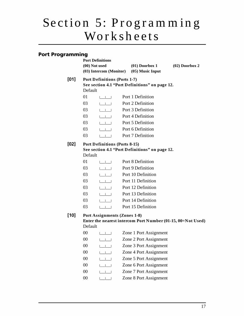
Port ProgrammingPort Definitions(00) Not used (01) Doorbox 1 (02) Doorbox 2(03) Intercom (Monitor) (05) Music Input
[01] Port Definitions (Ports 1-7)See section 4.1 “Port Definitions” on page 12.Default01 I_____I_____I Port 1 Definition
03 I_____I_____I Port 2 Definition03 I_____I_____I Port 3 Definition03 I_____I_____I Port 4 Definition03 I_____I_____I Port 5 Definition03 I_____I_____I Port 6 Definition03 I_____I_____I Port 7 Definition
[02] Port Definitions (Ports 8-15)See section 4.1 “Port Definitions” on page 12.Default01 I_____I_____I Port 8 Definition03 I_____I_____I Port 9 Definition03 I_____I_____I Port 10 Definition03 I_____I_____I Port 11 Definition
03 I_____I_____I Port 12 Definition03 I_____I_____I Port 13 Definition03 I_____I_____I Port 14 Definition03 I_____I_____I Port 15 Definition
[10] Port Assignments (Zones 1-8)Enter the nearest intercom Port Number (01-15, 00=Not Used)Default
00 I_____I_____I Zone 1 Port Assignment00 I_____I_____I Zone 2 Port Assignment00 I_____I_____I Zone 3 Port Assignment00 I_____I_____I Zone 4 Port Assignment00 I_____I_____I Zone 5 Port Assignment00 I_____I_____I Zone 6 Port Assignment
00 I_____I_____I Zone 7 Port Assignment00 I_____I_____I Zone 8 Port Assignment
18
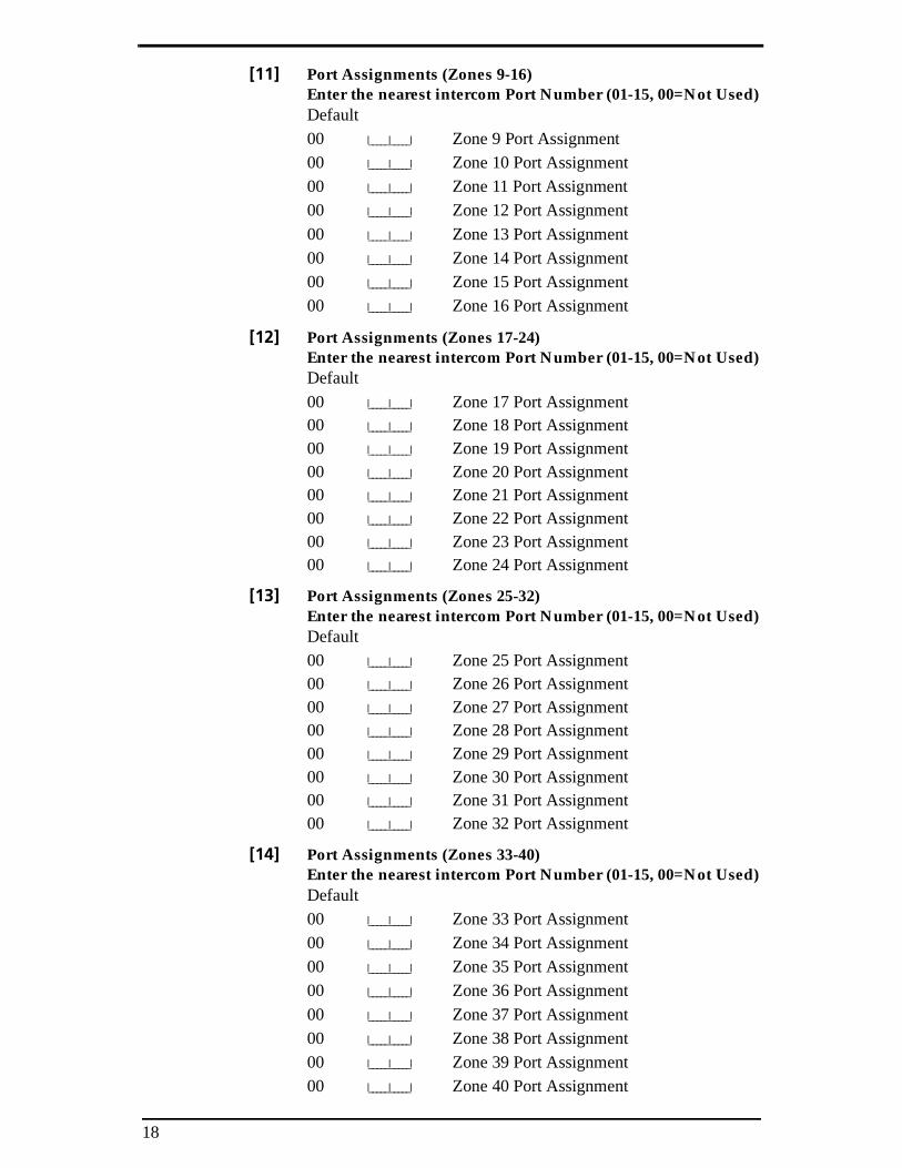
[11] Port Assignments (Zones 9-16)Enter the nearest intercom Port Number (01-15, 00=Not Used)Default00 I_____I_____I Zone 9 Port Assignment00 I_____I_____I Zone 10 Port Assignment00 I_____I_____I Zone 11 Port Assignment00 I_____I_____I Zone 12 Port Assignment
00 I_____I_____I Zone 13 Port Assignment00 I_____I_____I Zone 14 Port Assignment00 I_____I_____I Zone 15 Port Assignment00 I_____I_____I Zone 16 Port Assignment
[12] Port Assignments (Zones 17-24)Enter the nearest intercom Port Number (01-15, 00=Not Used)Default
00 I_____I_____I Zone 17 Port Assignment00 I_____I_____I Zone 18 Port Assignment00 I_____I_____I Zone 19 Port Assignment00 I_____I_____I Zone 20 Port Assignment00 I_____I_____I Zone 21 Port Assignment00 I_____I_____I Zone 22 Port Assignment00 I_____I_____I Zone 23 Port Assignment00 I_____I_____I Zone 24 Port Assignment
[13] Port Assignments (Zones 25-32)Enter the nearest intercom Port Number (01-15, 00=Not Used)Default00 I_____I_____I Zone 25 Port Assignment00 I_____I_____I Zone 26 Port Assignment00 I_____I_____I Zone 27 Port Assignment00 I_____I_____I Zone 28 Port Assignment00 I_____I_____I Zone 29 Port Assignment00 I_____I_____I Zone 30 Port Assignment00 I_____I_____I Zone 31 Port Assignment00 I_____I_____I Zone 32 Port Assignment
[14] Port Assignments (Zones 33-40)Enter the nearest intercom Port Number (01-15, 00=Not Used)Default00 I_____I_____I Zone 33 Port Assignment00 I_____I_____I Zone 34 Port Assignment00 I_____I_____I Zone 35 Port Assignment00 I_____I_____I Zone 36 Port Assignment
00 I_____I_____I Zone 37 Port Assignment00 I_____I_____I Zone 38 Port Assignment00 I_____I_____I Zone 39 Port Assignment00 I_____I_____I Zone 40 Port Assignment
19
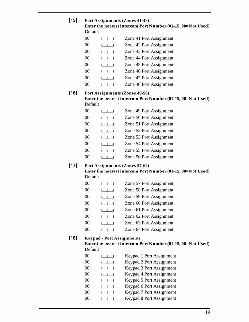
[15] Port Assignments (Zones 41-48)Enter the nearest intercom Port Number (01-15, 00=Not Used)Default00 I_____I_____I Zone 41 Port Assignment00 I_____I_____I Zone 42 Port Assignment00 I_____I_____I Zone 43 Port Assignment00 I_____I_____I Zone 44 Port Assignment
00 I_____I_____I Zone 45 Port Assignment00 I_____I_____I Zone 46 Port Assignment00 I_____I_____I Zone 47 Port Assignment00 I_____I_____I Zone 48 Port Assignment
[16] Port Assignments (Zones 49-56)Enter the nearest intercom Port Number (01-15, 00=Not Used)Default
00 I_____I_____I Zone 49 Port Assignment00 I_____I_____I Zone 50 Port Assignment00 I_____I_____I Zone 51 Port Assignment00 I_____I_____I Zone 52 Port Assignment00 I_____I_____I Zone 53 Port Assignment00 I_____I_____I Zone 54 Port Assignment
00 I_____I_____I Zone 55 Port Assignment00 I_____I_____I Zone 56 Port Assignment
[17] Port Assignments (Zones 57-64)Enter the nearest intercom Port Number (01-15, 00=Not Used)Default00 I_____I_____I Zone 57 Port Assignment00 I_____I_____I Zone 58 Port Assignment
00 I_____I_____I Zone 59 Port Assignment00 I_____I_____I Zone 60 Port Assignment00 I_____I_____I Zone 61 Port Assignment00 I_____I_____I Zone 62 Port Assignment00 I_____I_____I Zone 63 Port Assignment00 I_____I_____I Zone 64 Port Assignment
[18] Keypad - Port AssignmentsEnter the nearest intercom Port Number (01-15, 00=Not Used)Default00 I_____I_____I Keypad 1 Port Assignment00 I_____I_____I Keypad 2 Port Assignment00 I_____I_____I Keypad 3 Port Assignment00 I_____I_____I Keypad 4 Port Assignment00 I_____I_____I Keypad 5 Port Assignment00 I_____I_____I Keypad 6 Port Assignment00 I_____I_____I Keypad 7 Port Assignment00 I_____I_____I Keypad 8 Port Assignment
20
[20] First General Broadcast MaskDefault Option ON OFFOFF I_____I 1 For Future UseOFF I_____I 2 Incoming Sounds on Port 1 Enabled DisabledON I_____I 3 Incoming Sounds on Port 2 Enabled Disabled
ON I_____I 4 Incoming Sounds on Port 3 Enabled DisabledON I_____I 5 Incoming Sounds on Port 4 Enabled DisabledON I_____I 6 Incoming Sounds on Port 5 Enabled DisabledON I_____I 7 Incoming Sounds on Port 6 Enabled DisabledON I_____I 8 Incoming Sounds on Port 7 Enabled Disabled
[21] Second General Broadcast MaskDefault Option ON OFFON I_____I 1 Incoming Sounds on Port 8 Enabled DisabledON I_____I 2 Incoming Sounds on Port 9 Enabled DisabledON I_____I 3 Incoming Sounds on Port 10 Enabled Disabled
ON I_____I 4 Incoming Sounds on Port 11 Enabled DisabledON I_____I 5 Incoming Sounds on Port 12 Enabled DisabledON I_____I 6 Incoming Sounds on Port 13 Enabled DisabledON I_____I 7 Incoming Sounds on Port 14 Enabled DisabledON I_____I 8 Incoming Sounds on Port 15 Enabled Disabled
[30] Audio OptionsDefault Option ON OFFOFF I_____I 1 Follower Enabled DisabledOFF I_____I 2 Listen to All Zones Listen Only to
When On-Line Zones In AlarmOFF I_____I 3 Page Listens to All Page Waits for Answer
OFF I_____I 4 Doorbell Listens to All Doorbell Waitsfor Answer
OFF I_____I 5 Bell Silenced During Bell Active DuringVerbal Alarm Verbal Alarm Prompts
OFF I_____I 6 Audio Link Enabled DisabledOFF I_____I 7 For Future UseOFF I_____I 8 For Future Use
[31] Audio Options Two (For Future Use)Default Option ON OFFOFF I_____I 1 For Future UseOFF I_____I 2 For Future UseOFF I_____I 3 For Future Use
OFF I_____I 4 For Future UseOFF I_____I 5 For Future UseOFF I_____I 6 For Future UseOFF I_____I 7 For Future UseOFF I_____I 8 For Future Use
21
[32] Audio DurationDefault90 I_____I_____I (Valid Entries are 01-99 seconds)
00 For Future Use 09 Terminate Session01 Talk to all speakers 10 For Future Use02 For Future Use 11 Cancel First Keypress03 High Gain Listen to All 12 For Future Use04 For Future Use 13 Zone select (0 - 3 only)05 For Future Use 14 Increment Selected Microphone (input)06 Low Gain Listen to All 15 Decrement Selected Microphone (input)07 Extend Time 16 For Future Use08 For Future Use 17 Mode key
OFF I_____I 7 Opening After Alarm Enabled DisabledOFF I_____I 8 For Future Use
[60] Telephone Ring MaskDefault Option ON OFFOFF I_____I 1 For Future UseOFF I_____I 2 Port 1 Telephone Ring Enabled DisabledOFF I_____I 3 Port 2 Telephone Ring Enabled DisabledOFF I_____I 4 Port 3 Telephone Ring Enabled DisabledOFF I_____I 5 Port 4 Telephone Ring Enabled DisabledOFF I_____I 6 Port 5 Telephone Ring Enabled Disabled
OFF I_____I 7 Port 6 Telephone Ring Enabled DisabledOFF I_____I 8 Port 7 Telephone Ring Enabled Disabled
[61] Telephone Ring Mask TwoDefault Option ON OFFOFF I_____I 1 Port 8 Telephone Ring Enabled DisabledOFF I_____I 2 Port 9 Telephone Ring Enabled DisabledOFF I_____I 3 Port 10 Telephone Ring Enabled DisabledOFF I_____I 4 Port 11 Telephone Ring Enabled DisabledOFF I_____I 5 Port 12 Telephone Ring Enabled DisabledOFF I_____I 6 Port 13 Telephone Ring Enabled Disabled
OFF I_____I 7 Port 14 Telephone Ring Enabled DisabledOFF I_____I 8 Port 15 Telephone Ring Enabled Disabled
[62] Music Broadcast Mask OneDefault Option ON OFFOFF I_____I 1 For Future Use
ON I_____I 2 Port 1 Music Broadcast Enabled DisabledON I_____I 3 Port 2 Music Broadcast Enabled DisabledON I_____I 4 Port 3 Music Broadcast Enabled DisabledON I_____I 5 Port 4 Music Broadcast Enabled DisabledON I_____I 6 Port 5 Music Broadcast Enabled DisabledON I_____I 7 Port 6 Music Broadcast Enabled Disabled
ON I_____I 8 Port 7 Music Broadcast Enabled Disabled
23
[63] Music Broadcast Mask TwoDefault Option ON OFFON I_____I 1 Port 8 Music Broadcast EnabledON I_____I 2 Port 9 Music Broadcast Enabled DisabledON I_____I 3 Port 10 Music Broadcast Enabled Disabled
ON I_____I 4 Port 11 Music Broadcast Enabled DisabledON I_____I 5 Port 12 Music Broadcast Enabled DisabledON I_____I 6 Port 13 Music Broadcast Enabled DisabledON I_____I 7 Port 14 Music Broadcast Enabled DisabledON I_____I 8 Port 15 Music Broadcast Enabled Disabled
[70] Doorstrike Activation MaskDefault Option ON OFFOFF I_____I 1 For Future UseOFF I_____I 2 Port 1 Enabled to Activate Doorstrike DisabledOFF I_____I 3 Port 2 Enabled to Activate Doorstrike Disabled
OFF I_____I 4 Port 3 Enabled to Activate Doorstrike DisabledOFF I_____I 5 Port 4 Enabled to Activate Doorstrike DisabledOFF I_____I 6 Port 5 Enabled to Activate Doorstrike DisabledOFF I_____I 7 Port 6 Enabled to Activate Doorstrike DisabledOFF I_____I 8 Port 7 Enabled to Activate Doorstrike Disabled
[71] Doorstrike Activation Mask TwoDefault Option ON OFFOFF I_____I 1 For Future UseOFF I_____I 2 Port 8 Enabled to Activate Doorstrike DisabledOFF I_____I 3 Port 9 Enabled to Activate Doorstrike Disabled
OFF I_____I 4 Port 10 Enabled to Activate Doorstrike DisabledOFF I_____I 5 Port 11 Enabled to Activate Doorstrike DisabledOFF I_____I 6 Port 13 Enabled to Activate Doorstrike DisabledOFF I_____I 7 Port 14 Enabled to Activate Doorstrike DisabledOFF I_____I 8 Port 15 Enabled to Activate Doorstrike Disabled
FCC COMPLIANCE STATEMENTCAUTION: Changes or modifications not expresslyapproved by Digital Security Controls Ltd. couldvoid your authority to use this equipment.
This equipment has been tested and found to com-ply with the limits for a Class B digital device,pursuant to Part 15 of the FCC Rules. These limitsare designed to provide reasonable protectionagainst harmful interference in a residential instal-lation. This equipment generates, uses and canradiate radio frequency energy and, if not installedand used in accordance with the instructions, maycause harmful interference to radio communica-tions. However, there is no guarantee that interfer-ence will not occur in a particular installation. Ifthis equipment does cause harmful interference toradio or television reception, which can be deter-mined by turning the equipment off and on, theuser is encouraged to try to correct the interferenceby one or more of the following measures:
• Re-orient the receiving antenna.• Increase the separation between the equipment
and receiver.• Connect the equipment into an outlet on a cir-
cuit different from that to which the receiver is connected.
• Consult the dealer or an experienced radio/television technician for help.
The user may find the following booklet preparedby the FCC useful: “How to Identify and ResolveRadio/Television Interference Problems”. Thisbooklet is available from the U.S. GovernmentPrinting Office, Washington D.C. 20402, Stock #004-000-00345-4.
Important InformationThis equipment complies with Part 68 of the FCCRules. On the side of this equipment is a label thatcontains, among other information, the FCC regis-tration number of this equipment.
NOTIFICATION TO TELEPHONE COMPANY The cus-tomer shall notify the telephone company of theparticular line to which the connection will bemade, and provide the FCC registration number andthe ringer equivalence of the protective circuit.
FCC Registration Number: F53CAN-31477-KX-N
Ringer Equivalence Number: 0.1B
USOC Jack: RJ-31X
Facility Interface Code: 02LS2
Service Order Code: 9.0F
TELEPHONE CONNECTION REQUIREMENTS Exceptfor the telephone company provided ringers, allconnections to the telephone network shall bemade through standard plugs and telephone com-pany provided jacks, or equivalent, in such a man-ner as to allow for easy, immediate disconnectionof the terminal equipment. Standard jacks shall beso arranged that, if the plug connected thereto iswithdrawn, no interference to the operation of theequipment at the customer’s premises whichremains connected to the telephone network shalloccur by reason of such withdrawal.
INCIDENCE OF HARM Should terminal equipmentor protective circuitry cause harm to the telephonenetwork, the telephone company shall, where prac-ticable, notify the customer that temporary discon-nection of service may be required; however,where prior notice is not practicable, the telephonecompany may temporarily discontinue service ifsuch action is deemed reasonable in the circum-stances. In the case of such temporary discontinu-ance, the telephone company shall promptly notifythe customer and will be given the opportunity tocorrect the situation.
ADDITIONAL TELEPHONE COMPANY INFORMATION
The security control panel must be properly con-nected to the telephone line with a USOC RJ-31Xtelephone jack.
The FCC prohibits customer-provided terminalequipment be connected to party lines or to beused in conjunction with coin telephone service.Interconnect rules may vary from state to state.
CHANGES IN TELEPHONE COMPANY EQUIPMENT
OR FACILITIES The telephone company may makechanges in its communications facilities, equip-ment, operations or procedures, where suchactions are reasonably required and proper in itsbusiness. Should any such changes render the cus-tomer’s terminal equipment incompatible with thetelephone company facilities the customer shall begiven adequate notice to the effect modificationsto maintain uninterrupted service.
RINGER EQUIVALENCE NUMBER (REN) The RENis useful to determine the quantity of devices thatyou may connect to your telephone line and stillhave all of those devices ring when your telephonenumber is called. In most, but not all areas, thesum of the RENs of all devices connected to oneline should not exceed five (5.0). To be certain ofthe number of devices that you may connect toyour line, you may want to contact your local tele-phone company.
EQUIPMENT MAINTENANCE FACILITY If you expe-rience trouble with this telephone equipment,
Limited WarrantyDigital Security Controls Ltd. warrants the original purchaserthat for a period of twelve months from the date of purchase,the product shall be free of defects in materials and workman-ship under normal use. During the warranty period, DigitalSecurity Controls Ltd. shall, at its option, repair or replace anydefective product upon return of the product to its factory, atno charge for labour and materials. Any replacement and/orrepaired parts are warranted for the remainder of the originalwarranty or ninety (90) days, whichever is longer. The originalowner must promptly notify Digital Security Controls Ltd. inwriting that there is defect in material or workmanship, suchwritten notice to be received in all events prior to expiration ofthe warranty period.
International WarrantyThe warranty for international customers is the same as for anycustomer within Canada and the United States, with the excep-tion that Digital Security Controls Ltd. shall not be responsiblefor any customs fees, taxes, or VAT that may be due.
Warranty ProcedureTo obtain service under this warranty, please return the item(s)in question to the point of purchase. All authorized distributorsand dealers have a warranty program. Anyone returning goodsto Digital Security Controls Ltd. must first obtain an authoriza-tion number. Digital Security Controls Ltd. will not accept anyshipment whatsoever for which prior authorization has not beenobtained.
Conditions to Void WarrantyThis warranty applies only to defects in parts and workmanshiprelating to normal use. It does not cover:
• damage incurred in shipping or handling;
• damage caused by disaster such as fire, flood, wind, earth-quake or lightning;
• damage due to causes beyond the control of Digital SecurityControls Ltd. such as excessive voltage, mechanical shockor water damage;
• damage caused by unauthorized attachment, alterations,modifications or foreign objects;
• damage caused by peripherals (unless such peripherals weresupplied by Digital Security Controls Ltd.);
• defects caused by failure to provide a suitable installationenvironment for the products;
• damage caused by use of the products for purposes otherthan those for which it was designed;
• damage from improper maintenance;
• damage arising out of any other abuse, mishandling orimproper application of the products.
Digital Security Controls Ltd.’s liability for failure to repairthe product under this warranty after a reasonable number ofattempts will be limited to a replacement of the product, as theexclusive remedy for breach of warranty. Under no circum-stances shall Digital Security Controls Ltd. be liable for anyspecial, incidental, or consequential damages based uponbreach of warranty, breach of contract, negligence, strict lia-bility, or any other legal theory. Such damages include, but arenot limited to, loss of profits, loss of the product or any associ-ated equipment, cost of capital, cost of substitute or replace-ment equipment, facilities or services, down time, purchaser’stime, the claims of third parties, including customers, andinjury to property.
Disclaimer of Warranties
This warranty contains the entire warranty and shall be in lieu ofany and all other warranties, whether expressed or implied(including all implied warranties of merchantability or fitnessfor a particular purpose) And of all other obligations or liabili-ties on the part of Digital Security Controls Ltd. Digital SecurityControls Ltd. neither assumes nor authorizes any other personpurporting to act on its behalf to modify or to change this war-ranty, nor to assume for it any other warranty or liability con-cerning this product.
This disclaimer of warranties and limited warranty are governedby the laws of the province of Ontario, Canada.
WARNING: Digital Security Controls Ltd. recommends thatthe entire system be completely tested on a regular basis. How-ever, despite frequent testing, and due to, but not limited to,criminal tampering or electrical disruption, it is possible for thisproduct to fail to perform as expected.
Installer’s LockoutAny products returned to DSC which have the Installer’s Lock-out option enabled and exhibit no other problems will be subjectto a service charge.
Out of Warranty RepairsDigital Security Controls Ltd. will at its option repair orreplace out-of-warranty products which are returned to its fac-tory according to the following conditions. Anyone returninggoods to Digital Security Controls Ltd. must first obtain anauthorization number. Digital Security Controls Ltd. will notaccept any shipment whatsoever for which prior authorizationhas not been obtained.
Products which Digital Security Controls Ltd. determines tobe repairable will be repaired and returned. A set fee whichDigital Security Controls Ltd. has predetermined and whichmay be revised from time to time, will be charged for eachunit repaired.
Products which Digital Security Controls Ltd. determines not tobe repairable will be replaced by the nearest equivalent productavailable at that time. The current market price of the replace-ment product will be charged for each replacement unit.
Toronto, Canada 1-800-387-3630 • www.dsc.comPrinted in Canada 29005249 R001
AVIS: L’étiquette de l’Industrie Canada identifiele matériel homologué. Cette étiquette certifieque le matériel est conforme à certaines normesde protection, d’exploitation et de sécurité desréseaux de télécommunications. Industrie Can-ada n’assure toutefois pas que le matériel fonc-tionnera à la satisfaction de l’utilisateur.
Avant d’installer ce matériel, l’utilisateur doits’assurer qu’il est permis de le raccorder auxinstallations de l’entreprise locale de télécom-munication. Le matériel doit également êtreinstallé en suivant une méthode acceptée de rac-cordement. L’abonné ne doit pas oublier qu’il estpossible que la conformité aux conditions énon-cées ci-dessus n’empêchent pas la dégradationdu service dans certaines situations.
Les réparations de matériel homologué doiventêtre effectuées par un centre d’entretien cana-dien autorisé désigné par le fournisseur. Lacompagnie de télécommunications peutdemander à l’utilisateur de débrancher un appa-reil à la suite de réparations ou de modifica-tions effectuées par l’utilisateur ou à cause demauvais fonctionnement.
Pour sa propre protection, l’utilisateur doits’assurer que tous les fils de mise à la terre dela source d’énergie électrique, les lignes télé-phoniques et les canalisations d’eau métal-liques, s’il y en a, sont raccordés ensemble.Cette précaution est particulièrement impor-tante dans les régions rurales.
AVERTISSEMENT: L’utilisateur ne doit pastenter de faire ces raccordements lui-même; ildoit avoir recours à un service d’inspection desinstallations électriques, ou à un électricien,selon le cas.
L’indice de charge (IC) assigné a chaque dis-positif terminal indique, pour éviter toute sur-charge, le pourcentage de la charge totale quipeut être raccordée à un circuit téléphoniquebouclé utilisé par ce dispositif. La terminaison
du circuit bouclé peut être constituée den’importe quelle combinaison de dispositifs,pourvu que la somme des indices de charge del’ensemble des dispositifs ne dépasse pas 100.
L’Indice de charge de ce produit est 0.1B.
NOTICE: The Industry Canada label identifiescertified equipment. This certification meansthat the equipment meets certain telecommuni-cations network protective, operational andsafety requirements. Industry Canada does notguarantee the equipment will operate to theuser’s satisfaction.
Before installing this equipment, users shouldensure that it is permissible to be connected tothe facilities of the local telecommunicationscompany. The equipment must also be installedusing an acceptable method of connection. Thecustomer should be aware that compliance withthe above conditions may not prevent degrada-tion of service in some situations.
Repairs to certified equipment should be madeby an authorized Canadian maintenance facilitydesignated by the supplier. Any repairs oralterations made by the user to this equipment,or equipment malfunctions, may give the tele-communications company cause to request theuser to disconnect the equipment.
User should ensure for their own protectionthat the electrical ground connections of thepower utility, telephone lines and internalmetallic water pipe system, if present, are con-nected together. This precaution may be partic-ularly important in rural areas.
CAUTION: Users should not attempt to makesuch connections themselves, but should con-tact the appropriate electric inspection author-ity, or electrician, as appropriate.
The Load Number (LN) assigned to each termi-nal device denotes the percentage of the totalload to be connected to a telephone loop which