68
2014 Engineering Support ShurTite 5/12/2014 Installation Manual Rev. G

2014
Engineering Support
ShurTite
5/12/2014
Installation Manual Rev. G
WP#: WP2009-002
Date: Aug. 28 2012 / REV.G
Drafted: Engineering Dept
Approved: ECN
Engineering Support 280812-1
Confidential 2
Table of Contents Suggested Installation Tool List ................................................................................................................. 4
Trailer Modification ................................................................................................................................... 5 A) Front Build Out ................................................................................................................................. 5
B) Track Shims ...................................................................................................................................... 6
C) Internal Pockets ................................................................................................................................. 7 D) Combo Pockets ................................................................................................................................. 8
E) Winding Brace Mount Install .......................................................................................................... 10
Track Installation...................................................................................................................................... 11
A) Track Preparation ............................................................................................................................ 11
B) Track Mounting ............................................................................................................................... 12 C) Track Insert ..................................................................................................................................... 14
Headboard Installation ............................................................................................................................. 15
A) Positioning the Headboard .............................................................................................................. 15 B) Bolting the Headboard .................................................................................................................... 16
C) Welding the Headboard ................................................................................................................... 17
D) Man Door Step ................................................................................................................................ 18
E) Front Lock and Side Frames ............................................................................................................ 18
F) Wiring Harness Installation ............................................................................................................. 20
G) Headboard Handles - ....................................................................................................................... 21
H) Utility Shelf ..................................................................................................................................... 21 I) Dunage Racks and Chain Boxes ....................................................................................................... 22
J) “D” Rubber Installation .................................................................................................................... 22
DOT Headboard Installation .................................................................................................................... 23
Bows – Typically bows are shipped fully assemblied ....................................................................... 26 A) Corner Preparation .......................................................................................................................... 26
B) Front and Rear Corner Preparation ................................................................................................. 26
C) Intermediate Bow Assembly ........................................................................................................... 27 D) Front and Rear Bow Assembly ....................................................................................................... 27
E) Rear Bow Flap Extrusion ................................................................................................................ 28
F) Bow Installation ............................................................................................................................... 28
Front Lock Setup ...................................................................................................................................... 29
A) Hook Pocket Installation ................................................................................................................. 29
B) Bow Guide and Guide Plate ............................................................................................................ 29
Tarp Holders 1 .......................................................................................................................................... 30 A) Tarp Holder Preparation .................................................................................................................. 30
Tarps ......................................................................................................................................................... 32
A) Tarp Installation .............................................................................................................................. 32
Tarp Holder 2 ........................................................................................................................................... 33
A) Tarp Holder Installation .................................................................................................................. 33
B) Anchor Installation .......................................................................................................................... 33
Rear Post Setup ........................................................................................................................................ 34
A) Internal Posts ................................................................................................................................... 34 B) Combo Posts (External pocket) ....................................................................................................... 35
Tensioning ................................................................................................................................................ 36
A) Internal Posts ................................................................................................................................... 36

WP#: WP2009-002
Date: Aug. 28 2012 / REV.G
Drafted: Engineering Dept
Approved: ECN
Engineering Support 280812-1
Confidential 3
B) Combo Posts (External Posts) ......................................................................................................... 36 C) Rear Lock Brace Installation ........................................................................................................... 37
D) Rear Locks ...................................................................................................................................... 39
E) Wrinkles .......................................................................................................................................... 39
Track Installation 2................................................................................................................................... 40
A) Air Deflector ................................................................................................................................... 40
Up-Lifters ................................................................................................................................................. 40
A) Standard Lifters ............................................................................................................................... 40 B) Extra Lifters .................................................................................................................................... 41
Rear flap ................................................................................................................................................... 41
A) Rear Flap Preparation ...................................................................................................................... 41
B) Rear Flap Installation ...................................................................................................................... 42
C) Pulley and Rope installation ............................................................................................................ 43
D) Rear Flap Crank Installation and Operation .................................................................................... 44
E) Rear Flap Crank Holder Installation ................................................................................................ 45
E) Visor Installation ............................................................................................................................. 46 Locks and Handles ................................................................................................................................... 48
A) Safety Clip ...................................................................................................................................... 48
B) Strap Handle Installation ................................................................................................................. 48 Drop Deck Installation ............................................................................................................................. 49
A) Trailer Deck preparation ................................................................................................................. 49
Install Procedure-Drop Doors .............................................................................................................. 53
C) Piggy Back Installation ................................................................................................................... 54
Front End Build Out ................................................................................................................................. 57
Rear Step Installation ............................................................................................................................... 59
Tarp Repair ............................................................................................................................................... 60
Final Testing and Sealing ......................................................................................................................... 60 A) Functional Testing........................................................................................................................... 60
B) Sealing the System .......................................................................................................................... 61 Sticker Location: Place stickers as shown ................................................................................................ 61
Nut and Bolt Torque Specifications ......................................................................................................... 62
TRAINING CHECK LIST ....................................................................................................................... 63 In House System Discharge and Quality Checklist .............................................................................. 64
Inspection and Tarp System Operation ................................................................................................ 65
Inspection and Maintenance ................................................................................................................. 66
Monthly Inspection Schedule ............................................................................................................... 67
SAFETY ALERT ..................................................................................................................................... 68

WP#: WP2009-002
Date: Aug. 28 2012 / REV.G
Drafted: Engineering Dept
Approved: ECN
Engineering Support 280812-1
Confidential 4
Suggested Installation Tool List – May require some or all listed.
1. Aluminium welder and or Steel welder – dependent on trailer make/model
2. Circular/Skill saw to cut alum. 3. Hand drill – 1/2” chuck
4. Grinder – Alum/Steel 5. Plasma Cutter - (not an absolute necessity but it helps)
6. Wire brush-To clean welds
7. Utility Knife- to cut track rubber 8. Black marker
9. Sliding bar clamps – 8 to10 pcs or10 to12 heavy vice grip locking pliers to mount track
10. Impact gun - 3/8 or 1/2” drive - same as sockets
11. Adjustable Tri square – weld track tabs perpendicular to deck
12. 2 ft. carpenter square or level – set headboard angle
13. Measure Tape
14. Hammer – install tarp anchors
15. Heavy C-Clamp vice grip with swivel pads or c-clamp – install tarp anchors 16. Cocking gun – Seal headboard
17. 24” long pry bar – install tarp anchors
18. 1” – 82° counter sink – for track bolts
19. 3/16 Rivet gun
20. Pliers- install tarp anchors
21. Wire strippers – headboard lights
22. Side cutters – headboard light wiring, cut straw for tarp anchor install 23. 3” hole saw – wheel access hole in track
24. 2-3/4” hole saw
25. Ability to cut holes for any size trailer lights at front or rear 26. 3/4” socket
27. 3/4” wrench
28. 1/2” wrench - rope and pulley install/-over 90 bar latch
29. 7/32 hex key socket - 3/8 track bolt, steel trailer
30. 5/16 hex key socket – 1/ 2” track bolt, alum trailer
31. 9/16 wrench
32. 9/16 socket
33. 1/2” drill bit 34. 3/8” drill bit
35. #3 (Black) Robertson screw driver - lock brace guide 36. 7/16 wrench - lock brace guide
37. 1/4” drill bit - hole for tether
38. 13/64 drill bit – rivets 39. Diagonal brace for headboard mounting angle – 2 pcs, minimum 8ft. lg (wood 2x4, steel angle, alum
angle)
40. Floor Jack – mount track (not an absolute necessity but it helps)
41. Some method to bend small pieces of aluminum or steel

WP#: WP2009-002
Date: Aug. 28 2012 / REV.G
Drafted: Engineering Dept
Approved: ECN
Engineering Support 280812-1
Confidential 5
Trailer Modification A) Front Build Out – Front corner must be square to front and sides of deck.
Steps: 1. Remove obstructions from the front corners of the trailer. Each trailer make is different.
2. Measure the width of the base plate of the headboard and build your build-out to match the width.
3. Tack weld the build out to the trailer making sure the cap sits flush with the deck of the trailer, and weld in place both Build-Out and Cap.
Hint: It may be necessary to add extra material not included with the kit
4. Add one, track rubber plate 5 inches from the top of the deck behind the build-out, and one, track rubber plate ahead of the last pocket to the rear 5 inches from the top of the deck to fasten the track rubber to later.

WP#: WP2009-002
Date: Aug. 28 2012 / REV.G
Drafted: Engineering Dept
Approved: ECN
Engineering Support 280812-1
Confidential 6
Ratchet Post
Note: Paint is required with steel trailers
The Track Rubber, must be installed fully between the inside of the rear pocket and front build out to seal the trailer from dirt and water;
B) Track Shims Steps:
1. Cut away a 5” section of the rub rail from the approximate middle of the trailer for changing the 3” wheel assemblies if repair is necessary.
WP#: WP2009-002
Date: Aug. 28 2012 / REV.G
Drafted: Engineering Dept
Approved: ECN
Engineering Support 280812-1
Confidential 7
2. Weld on the 1/4" track shims below and flush with the rub rail perpendicular to deck. Track shims are installed every other stake pocket where the bolts will go.
3. Mark the deck at the center of the stake pockets to locate the shims for Track Installation (page 12)
Note: additional 1/8 shims, are needed in the middle of the rub rail itself when the track will not sit flush with the rub rail.
For systems with posts and ratchet tensioning system.
C) Internal Pockets Steps
1. The pocket is welded flush to the deck, 8 inches from the rear of the trailer on an angle of 5/8” over 2’ from bubble level
Note: Pockets angled back to allow the posts more room to flex forward during tensioning
2. Ensure that the pocket is bubble level (perpendicular to the deck) on the sides to ensure proper installation of the track later
3. Weld the pocket solid to the trailer on both sides of the pocket and the underside 4. Weld in the 2” x 5” gusset plates to both sides of the pocket 1/4 inch from the deck 5. Tack weld a 2” x 5” plate flush to the end of the trailer a 1/4 inch from the deck 6. Test fit the 6” x 8” strength plate flush to the side of the pocket and to the side of the 2” x 5” plate

WP#: WP2009-002
Date: Aug. 28 2012 / REV.G
Drafted: Engineering Dept
Approved: ECN
Engineering Support 280812-1
Confidential 8
7. Weld the 2” x 5” plate solid and weld the strength plate solid to the pocket and the 2” x 5” plate
` 8. Weld the triangle cap to the front gusset and pocket 9. Weld the 2” x 8” Strength plate cap into position 10. Weld a 1/8 track rubber plate to the internal pockets 5” down and parallel to the deck 11. A length of chain is installed to the top of the triangle cap with ¼ inch huck rivet and washer to secure the
posts later.
D) Combo Pockets -To use posts inside or out
Steps:
1. See internal pockets steps 1 to 4
2. Tack weld in the 2” x 5” gusset plates to both sides of the pocket ¼ inch from the deck 3. Position the external pocket at the rear of the trailer approx. 8” from the internal pocket and line it up with
the outside of the internal pocket to allow the track to sit straight later 4. Angle to ext. pocket the same as the (step 1) internal and tack in place

WP#: WP2009-002
Date: Aug. 28 2012 / REV.G
Drafted: Engineering Dept
Approved: ECN
Engineering Support 280812-1
Confidential 9
Note: There will be a gap at the top of the pocket from angling the pocket back, fill with weld; The high heat will make the pocket turn so make sure to distribute the heat evenly on all sides
5. Adjust and weld solid 6. Tack weld in two more of the gusset plates to either side of the external pocket on the corner of the trailer 7. With the pockets aligned, weld the gusset plates solid to the trailer and pockets 8. Tack weld the bumper 3” x 5” plate side into place approx. 5 inches away from the external pocket and ¼
inch down from the deck 9. Test fit the 5” x 6” bumper plate face so that it sits square with the pocket and the side plate 10. Weld the 3” x 5” side plate solid on both sides 11. Weld the bumper face to the side plate and external pocket
Note: Weld on the inside as much as possible
12. Weld the caps for the rear bumper, the strength plate and gusset plate toward the front of the trailer
13. Weld a 1/8 track rubber plate to the internal pockets 5” down and parallel to the deck Trailer modification (see photo page 9)
14. A length of chain is installed to the top of the triangle cap with a ¼ huck rivet and washer to secure the internal posts (see photo page 9)
15. A length of chain is installed to the bumper cap with a ¼ huck rivet and washer to secure the combo pockets

WP#: WP2009-002
Date: Aug. 28 2012 / REV.G
Drafted: Engineering Dept
Approved: ECN
Engineering Support 280812-1
Confidential 10
For systems with Winding Brace tensioning system
E) Winding Brace Mount Install
Steps: 1. Remove or modify any obstructions located in the installation area prior to installation of the Rear Lock
Brace Mount. 2. Weld a, 1/8 x 2 x 4 track rubber plate 5” down and parallel to the deck or on the underside of a stake
pocket, whatever is the furthest point to the rear. This will allow for a proper seal of the system later
3. Place the, Base Plate into position as depicted in the drawing above. 4. The Base plate will sit on top of the rub rail and flush with the deck, 6” from the rear of the trailer.
5. Tack weld, the base plate into position with several welds to prevent the base from warping. Weld the base solid to the trailer. Note: You may have to add additional support and or remove material to mount Base Plate.

WP#: WP2009-002
Date: Aug. 28 2012 / REV.G
Drafted: Engineering Dept
Approved: ECN
Engineering Support 280812-1
Confidential 11
6. Install the guide rail mount 30” for 72 or 100H or 40” for Drop Deck from the rear of the Base Plate in
the same manner as the base plate. 7. Place the base weldment on top of the base plate with the hooks open towards the rear of the trailer.
Note: The weldment must align with the holes already in the base plate. The hex head bolt toward the front of the trailer. 8. Insert hardware provided and fasten to the trailer. 9. Place the Rail Lock channel on the Base rail, align and drill and countersink 3 holes for 1/4” flat head
bolts RTC-11202 and nuts RTC-17751 install the bolts at either end of the rail and one in the center making sure they are, flush with the Guide Rail.
10. Repeat installation procedure for the other side in mirror.
Track Installation
A) Track Preparation Steps:
1. To measure the track required you must measure from the rear end of the deck (add 2” to overall length) all the way up to the headboard wings or 9” from the front without the headboard installed (add 2” to overall length, THE TRACK WILL EXTEND BEYOND THE END OF THE TRAILER BUT NOT BEYOND THE BUMPER)
2. Transfer this measurement to the track and cut Note: The track rubber length is the distance between the front build out and last pocket to the rear. (see photo page 6) Measure, from each end the distance to the track rubber mounts, and mark on the track.
Note: For 53 ft. trailers you will need to add 5 ft of track to the front see step 7.
3. Be sure to remove any burr from the end of the track where the track rubber will be inserted
4. Blow out the slot for the track rubber the entire length of the track.
5. Feed track rubber into the channel provided in the track extrusion
6. Pull the track rubber into the track up to the previously marked line and cut (allow for stretch) Hint: You can use lubricant to help the rubber slip in the channel more easily.
WP#: WP2009-002
Date: Aug. 28 2012 / REV.G
Drafted: Engineering Dept
Approved: ECN
Engineering Support 280812-1
Confidential 12
7. Insert the track rubber in the 48 ft. length of track allowing 6 to 8 inches of track rubber to extend beyond the front end.
B) Track Mounting Rev E
Note: Rear Lock Brace mount Plates, or Post Pockets, and front corner build out, and track rubber must be installed before track mounting. Steps:
1. Lift the track into the approximate required position 3/8 to1/2 inch from the deck to the top of the track. This distance must be consistent from front to back on both sides.
2. Clamp with 6 or 7 bar clamps evenly spaced along trailer.
Note: Place the clamps in stake pockets, that do not have the track tabs. This is where the bolts go. Top of track must be below the deck edge the same distance from front to back and side to side.

WP#: WP2009-002
Date: Aug. 28 2012 / REV.G
Drafted: Engineering Dept
Approved: ECN
Engineering Support 280812-1
Confidential 13
3. Starting from the rear, loosen one or two bar clamps and set the top of the track 1/2 inch from the top of
the deck. Re-tighten clamp. Repeat for other side.
4. Drill appropriate sized holes for the hardware provided (1/2” bolts for aluminium trailers and 3/8” blots for steel trailers) at approximately 1/4 inch up from the center of the wide space on the track into the stake pockets that were previously marked. See track shims.
5. Counter sink the holes to allow a flush mount of the bolts. Hint: The head of the bolt should be not more than 1/32 above the surface. Be careful not to countersink too much.
6. Start from the rear at the ends of the track (last pocket to rear), repeat steps 4 and 5 with the last bolt in the front corner build-out.
7. Insert the bolt in the holes and fasten with a nylon insert lock nut.
8. Hold the nut with a wrench and tighten with the impact wrench. Give the nut an additional turn with the wrench to ensure they are tight.
9. Cut a 3 inch hole through the track at about center of the trailer where the 5 inch
section of rub rail was previously cut out
10. Remove the bar clamps and clean out the debris with an air gun.
11. Rivet the track rubber to the 1/8 track rubber plates previously installed during Trailer Modification . (2 rivets at each end)
12. For 53 ft. trailer install the rear track section first leaving out the last bolt toward the front
13. Align the front section with the rear and clamp into place

WP#: WP2009-002
Date: Aug. 28 2012 / REV.G
Drafted: Engineering Dept
Approved: ECN
Engineering Support 280812-1
Confidential 14
14. Weld the ends of the track together only in the wide section of the track
Note: Both ends must align exactly or you may have problems inserting the track insert.
15. Overlap the rubber and fasten with rivets. Complete the join with silicon after the track is installed.
C) Track Insert Steps:
1. Insert the white nylon track insert into one side of the track. Fill the track from the Side Frames to the rear of the track.
Note: If the headboard is not installed, secure at the front with a pair of vice grips. Do not proceed to the next step until the headboard, and the wings (side frames) have been installed.

WP#: WP2009-002
Date: Aug. 28 2012 / REV.G
Drafted: Engineering Dept
Approved: ECN
Engineering Support 280812-1
Confidential 15
2. Push the track insert towards the front of the trailer and make sure there are no gaps in the track insert.
Temporarily hold in position with a vice grip.
3. Drill a clearance hole for a 3/8 bolt through the track from top to bottom passing through the center of the white nylon insert approximately one inch from the end of the track and insert the bow stopper bolt assembly. Trim excess track insert.
4. Repeat for the other side.
Note: The joins in the white nylon insert should be staggered from one side to the other to ease the movement of the bows.
Headboard Installation
A) Positioning the Headboard Steel Trailers: Add duct tape to the bottom of the headboard to be a barrier against corrosion.
Steps:
1. Lift the headboard onto the trailer deck 2. Align and center the headboard with the front of the trailer and on both sides 3. Attach the headboard braces and clamp the head board foot plate with bar-clamps 4. Set the headboard angle by adjusting the headboard braces and checking with the 24” square measuring
the distance at the bottom of the square and then at the top to make sure that the headboard is set at 90 degrees to the deck. A forward lean of not more than 1/32” is exceptable.

WP#: WP2009-002
Date: Aug. 28 2012 / REV.G
Drafted: Engineering Dept
Approved: ECN
Engineering Support 280812-1
Confidential 16
Note: Add shims to fill gap under Headboard at bolt locations. Too much gap under the headboard and it might
bow at the top when bolts are installed. Hint: You can use a forklift to hold the headboard position if you do not have braces.
B) Bolting the Headboard Steps:
1. Use a pilot bit to ensure there will be no issues with existing bolts in deck and re-drill 1/2" holes as per diagram below.
Note: 8 (1-3/4”), and 15 (3-1/2”) bolts supplied. Adjust this pattern to suite the individual trailer. Account for airlines, beams, wiring, and any other variables.

WP#: WP2009-002
Date: Aug. 28 2012 / REV.G
Drafted: Engineering Dept
Approved: ECN
Engineering Support 280812-1
Confidential 17
2. Insert the bolts and attach the washers and nuts from underneath using a wrench and an impact wrench. Aluminium washer plates are generally not required for the bolts along the very front of the trailer.
3. Re-check the angle of the headboard to ensure it is still at 90 degrees to the deck. Hint: Use structural angel to span underside of wood deck.
C) Welding the Headboard Steps:
1. With the headboard aligned at 90 degrees, you can now weld around the posts and gussets on the inside of the headboard to lock the position. Additional, welds are, needed along the front corners between the base plate and the headboard itself
2. For aluminium trailers weld along the seam between the front of the trailer and the headboard mount plate. Grooving may be required to allow for better penetration of the weld.
WP#: WP2009-002
Date: Aug. 28 2012 / REV.G
Drafted: Engineering Dept
Approved: ECN
Engineering Support 280812-1
Confidential 18
Note: Care, must be taken to protect the finish of the headboard from welding spatter
D) Man Door Step For Headboards with man door
Steps:
1. Position the step in the middle of the headboard under the man-door between the bottom of the man-door and the base plate of the headboard with the treaded side facing up.
2. Make sure to square the step to the headboard. 3. Weld a tack on both ends of the step and re-adjust the step to
square 4. With the step square to the face of the headboard, weld the step solid making sure not to be too hot and
blow through the headboard material.
E) Front Lock and Side Frames – Hint: Check the alignment of the holes before inserting bolts. Steps:
1 Lift the Slide lock assembly to the right or left side of the headboard and insert the 6 bolts through the pre-drilled 3/8” holes and tighten. Repeat for the other side.
2 Remove the handle assembly, and grease the slide bar at the 3 guides.
3 Slide the appropriate side frame (wing) onto the slide locks making sure to slide the bottom handle mount through the tarp seal on the inside of the side frame and out through the slot.

WP#: WP2009-002
Date: Aug. 28 2012 / REV.G
Drafted: Engineering Dept
Approved: ECN
Engineering Support 280812-1
Confidential 19
4 Bolt the side frame (wing) into position using the pre-drilled holes in the headboard making sure that it aligns with the top of the headboard and the front is flush.
5 A hole will need, to be, drilled into the front build out to accommodate the additional bolt located at the bottom of the wings (side frames).
6 Mount the handles by using the hardware provided making sure not to tighten too tight to allow for movement at the joints.
7 Silicone is required at this stage on the top of the wing cap and on the inside of the wing where the bow will seal with the headboard, where the “D” rubber is mounted.
This sealing must be done to accommodate, the, ”D” Rubber Installation (page 17) Note: Further sealing, is done during the final phase of installation.
WP#: WP2009-002
Date: Aug. 28 2012 / REV.G
Drafted: Engineering Dept
Approved: ECN
Engineering Support 280812-1
Confidential 20
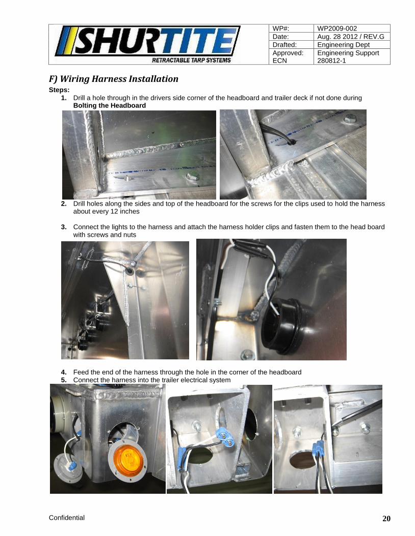
F) Wiring Harness Installation Steps:
1. Drill a hole through in the drivers side corner of the headboard and trailer deck if not done during Bolting the Headboard
2. Drill holes along the sides and top of the headboard for the screws for the clips used to hold the harness
about every 12 inches 3. Connect the lights to the harness and attach the harness holder clips and fasten them to the head board
with screws and nuts
4. Feed the end of the harness through the hole in the corner of the headboard 5. Connect the harness into the trailer electrical system
WP#: WP2009-002
Date: Aug. 28 2012 / REV.G
Drafted: Engineering Dept
Approved: ECN
Engineering Support 280812-1
Confidential 21
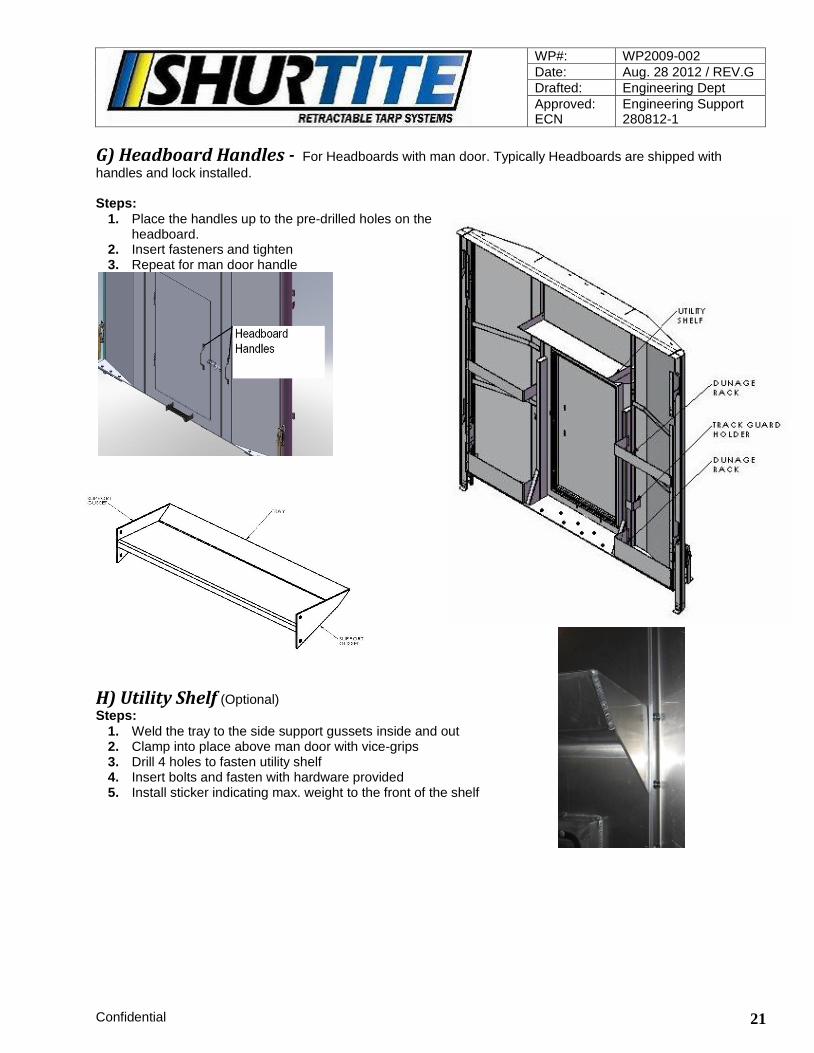
G) Headboard Handles - For Headboards with man door. Typically Headboards are shipped with
handles and lock installed. Steps:
1. Place the handles up to the pre-drilled holes on the headboard.
2. Insert fasteners and tighten 3. Repeat for man door handle
H) Utility Shelf (Optional)
Steps:
1. Weld the tray to the side support gussets inside and out 2. Clamp into place above man door with vice-grips 3. Drill 4 holes to fasten utility shelf 4. Insert bolts and fasten with hardware provided 5. Install sticker indicating max. weight to the front of the shelf
WP#: WP2009-002
Date: Aug. 28 2012 / REV.G
Drafted: Engineering Dept
Approved: ECN
Engineering Support 280812-1
Confidential 22
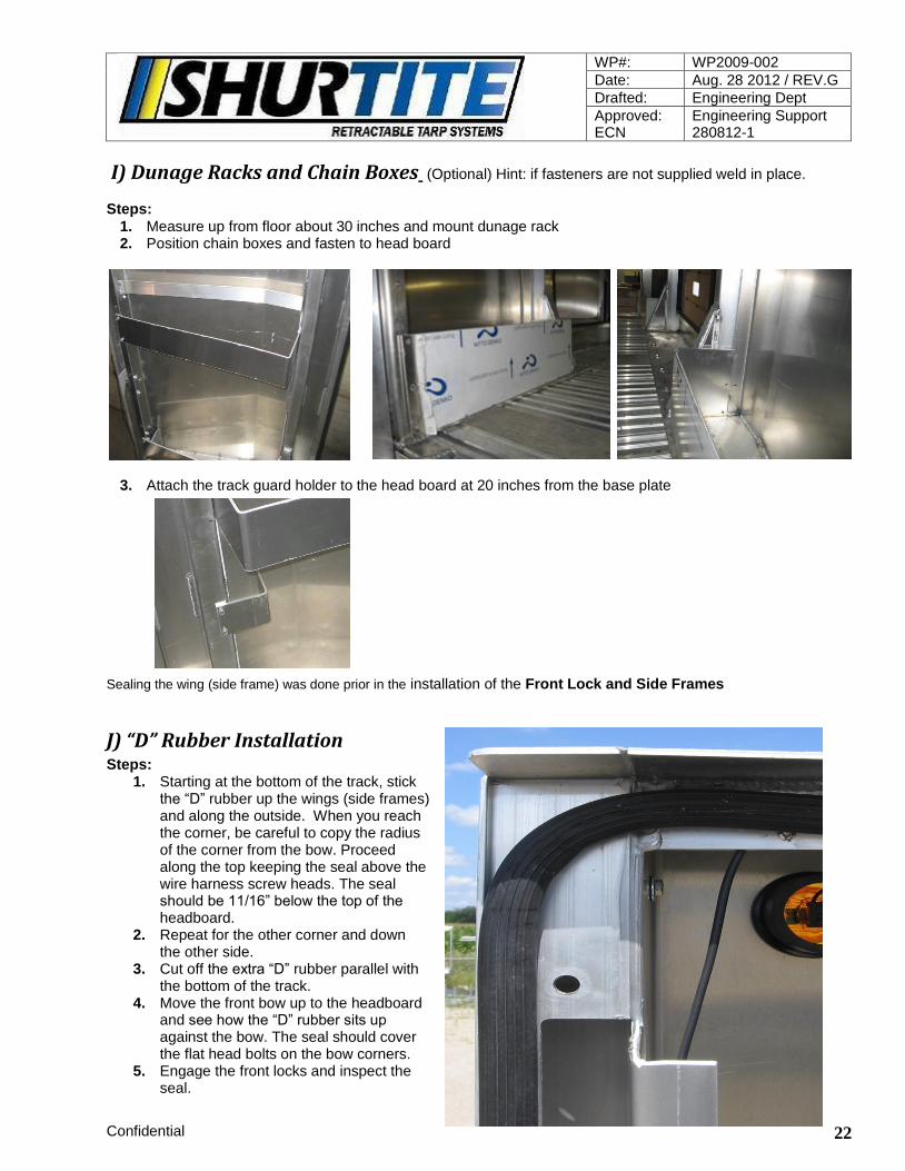
I) Dunage Racks and Chain Boxes (Optional) Hint: if fasteners are not supplied weld in place.
Steps:
1. Measure up from floor about 30 inches and mount dunage rack 2. Position chain boxes and fasten to head board
3. Attach the track guard holder to the head board at 20 inches from the base plate
Sealing the wing (side frame) was done prior in the installation of the Front Lock and Side Frames
J) “D” Rubber Installation Steps:
1. Starting at the bottom of the track, stick the “D” rubber up the wings (side frames) and along the outside. When you reach the corner, be careful to copy the radius of the corner from the bow. Proceed along the top keeping the seal above the wire harness screw heads. The seal should be 11/16” below the top of the headboard.
2. Repeat for the other corner and down the other side.
3. Cut off the extra “D” rubber parallel with the bottom of the track.
4. Move the front bow up to the headboard and see how the “D” rubber sits up against the bow. The seal should cover the flat head bolts on the bow corners.
5. Engage the front locks and inspect the seal.
WP#: WP2009-002
Date: Aug. 28 2012 / REV.G
Drafted: Engineering Dept
Approved: ECN
Engineering Support 280812-1
Confidential 23
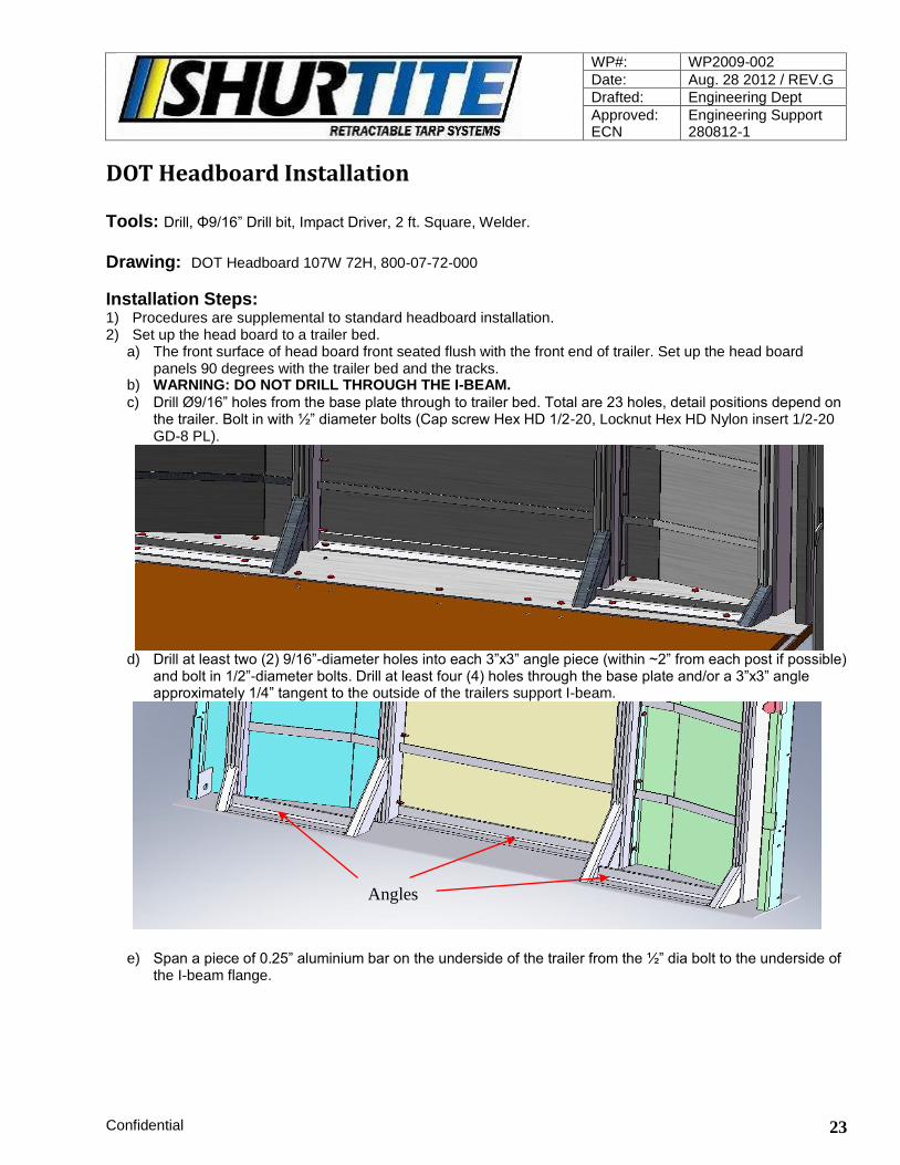
DOT Headboard Installation Tools: Drill, Φ9/16” Drill bit, Impact Driver, 2 ft. Square, Welder. Drawing: DOT Headboard 107W 72H, 800-07-72-000
Installation Steps: 1) Procedures are supplemental to standard headboard installation. 2) Set up the head board to a trailer bed.
a) The front surface of head board front seated flush with the front end of trailer. Set up the head board panels 90 degrees with the trailer bed and the tracks.
b) WARNING: DO NOT DRILL THROUGH THE I-BEAM.
c) Drill Ø9/16” holes from the base plate through to trailer bed. Total are 23 holes, detail positions depend on the trailer. Bolt in with ½” diameter bolts (Cap screw Hex HD 1/2-20, Locknut Hex HD Nylon insert 1/2-20 GD-8 PL).
d) Drill at least two (2) 9/16”-diameter holes into each 3”x3” angle piece (within ~2” from each post if possible)
and bolt in 1/2”-diameter bolts. Drill at least four (4) holes through the base plate and/or a 3”x3” angle approximately 1/4” tangent to the outside of the trailers support I-beam.
e) Span a piece of 0.25” aluminium bar on the underside of the trailer from the ½” dia bolt to the underside of the I-beam flange.
Angles

WP#: WP2009-002
Date: Aug. 28 2012 / REV.G
Drafted: Engineering Dept
Approved: ECN
Engineering Support 280812-1
Confidential 24
f) After headboard base plate has been aligned and secured to the trailer deck, and proper vertical angle for the headboard has been achieved:
g) Weld angles to the tube gussets and posts with a 0.25” continuous fillet along the perimeter. h) Stitch welds the middle angle to the front panel sheet with 6” x 0.25” fillet at the right, left sides and in the
middle. i) Weld all gussets and angles to the base plate using a 0.25” continuous fillet.
Gusset Toes
Angles
1/4” Aluminium Bar
Trailer Support I-Beam Flange

WP#: WP2009-002
Date: Aug. 28 2012 / REV.G
Drafted: Engineering Dept
Approved: ECN
Engineering Support 280812-1
Confidential 25
j) Drill at least two (2) 9/16”-diameter holes into each 3”x3” angle piece (within ~2” from each post if possible) and bolt in 1/2”-diameter bolt.
k) Drill at least four (4) holes through the base plate and/or a 3”x3” angle approximately 1/4” tangent to the
outside of the trailers support I-beam. Span a piece of 0.25” aluminium bar on the underside of the trailer from the 0.50” dia bolt to the underside of the I-beam flange. WARNING: DO NOT DRILL THROUGH THE I-BEAM.
l) Install remaining components to the headboard as standard installation procedure (ie. Wings, wiring etc.)
Two (2) or more bolts per angle

WP#: WP2009-002
Date: Aug. 28 2012 / REV.G
Drafted: Engineering Dept
Approved: ECN
Engineering Support 280812-1
Confidential 26
Reference only - Hole pattern may vary as per installation
Bows – Typically bows are shipped fully assemblied
A) Corner Preparation Note: Prepare and then install. Do not prepare all the corners prior to installation!
Steps:
1. Before assembly, apply silicone gasket material to one face and press the 2 corner halves together.
2. Install corner assembly and clean away excess silicone. See Intermediate/Front and Rear Bow Assembly Procedure (page 22,23)
Note: Flat head bolts are to be inserted towards rear or front (headboard) on the front and rear bows.
B) Front and Rear Corner Preparation
Flush mounted (counter sunk) cast corners are paired up with standard corners. They are, sealed in the same manner as above.
WP#: WP2009-002
Date: Aug. 28 2012 / REV.G
Drafted: Engineering Dept
Approved: ECN
Engineering Support 280812-1
Confidential 27
Note: The flush mount (counter sunk) corners are for the seal with the headboard and for the rear flap. Corner Preparation must be done prior to each assembly
C) Intermediate Bow Assembly Steps:
1. Assembly of an intermediate bow requires two side assemblies, a top tube, two pairs of cast corners and the hardware.
2. Apply blue silicone gasket material all around both ends of the cast corner assembly. (be sure to apply silicone to the face of the channel area).
3. With a pair of corners sealed, install in the tubes and fasten with the hardware provided.
Note: have all the button head bolts facing the same direction toward the rear.
4. Build remaining intermediate bows, always sealing and then installing
D) Front and Rear Bow Assembly Note: On each side assembly, one channel tube is blocked or ground. The two sides must be on the same side to allow the tarp to pass
WP#: WP2009-002
Date: Aug. 28 2012 / REV.G
Drafted: Engineering Dept
Approved: ECN
Engineering Support 280812-1
Confidential 28
Steps: 1. Assembly of a Front and Rear Bow requires two side assemblies with the lock plates in the same location,
a top assembly, two pairs of cast corners, two pairs of counter sunk corners, two corner supports, and the hardware.
2. With the cast corners sealed insert the appropriate corner into the channel tubes Note: counter sunk corners are for the non blocked/ground channels
3. Insert fasteners provided to hold together. 4. Repeat for the other side 5. Next install the corner supports between the cast corners and fasten with hardware (this will draw the
corners together tightly) 6. Follow by fastening the cast corners
Note: the lettering on the cast corners may need to be ground down to allow the corner support to be installed
E) Rear Bow Flap Extrusion Steps:
1. Place, the rear flap holder channel on the top tube assembly, with the opening facing towards the feet. 2. Center the two sides and position it so that it sits flush with the top of the bow tube. Mark and trim the
overhang. 3. Place four Tack welds on the top, one at each end and evenly spaced in the middle. On the underside
tack weld in three places staggered to the top welds. 4. Return to tacks and weld 2 inch welds for each.
Note: Do not weld to the cast corners; weld only to the channel tube material.
5. Let the material cool and then seal with silicone.
F) Bow Installation Steps:
1. Remove the bow stopper bolts from the end of the tracks 2. Lift and push onto the tracks the front bow with the flush mounted corners (flat head bolts) facing the
headboard, secure the bow with a clamp 3. Next, lift and push onto the tracks each of the intermediate bows with the button head bolt facing the
rear, and secure with a clamp 4. Last, lift and push on the rear bow with the flush mount corners (flat head bolts) facing the rear. Secure
the bow with a clamp and re-install the rear stopper bolts
WP#: WP2009-002
Date: Aug. 28 2012 / REV.G
Drafted: Engineering Dept
Approved: ECN
Engineering Support 280812-1
Confidential 29
Front Lock Setup
A) Hook Pocket Installation Steps:
1. With the D-rubber seal installed, push the front bow up to the headboard 2. With the front locks in their down position(locked) mark the location of the bottom of the hook and remark
a 1/8 inch below to allow for clearance with a marker 3. Move the bow away from the headboard and drill 2 holes through the bow to mount the hook pocket 4. Insert and tighten the fasteners 5. Repeat the same for both sides 6. Push the bow up to the headboard and lock it 7. Add or remove shims to make adjustments
Inspect the seal after Tensioning (page 31) has been applied to see
the quality of the seal. Install spacers between the bow tube and the hook pockets to add additional seal.
B) Bow Guide and Guide Plate Steps:
1. Mark 77 inches from the base plate of the headboard up the side of the headboard. This will be the top of the mounting position for the bow guide
2. Repeat for other side 3. Roll the bow up to the headboard. Place the bow guide plate
between the bow and the bow guide. Clamp the bow guide into place and repeat for other side
4. Center the bow guide plate with the bow guide and mark 5. Center the bow against the headboard to ensure ease of locking
with the slide locks 6. Drill the holes and mount with the hardware provided
Note: Do not install the bow guide so tight that the bow does not pass

WP#: WP2009-002
Date: Aug. 28 2012 / REV.G
Drafted: Engineering Dept
Approved: ECN
Engineering Support 280812-1
Confidential 30
Tarp Holders 1 A) Tarp Holder Preparation - Tarp Holders are shipped pre-drilled and numbered to match the
bow feet they belong to. Steps:
1. Measure down 1/2“from the bottom of the channel tube and place a mark on
the foot below the channel tube. (mark all feet at the same time)
2. Place 2 pieces of flat bar on either side of the channels and clamp in place with
the vice grips.
3. Slide the tarp holder in between the flat bar and up to the 1/2” mark made earlier to align the holder with the channel tube and clamp with the vice grip.
4. Drill a rivet hole through the tarp holder and bottom of foot as shown.
5. Remove one piece of flat bar and Insert a piece of flat bar in the slots in the
channel tube and tarp holder to insure correct alignment.
6. Drill a rivet hole through the tarp holder and upper part of the foot as shown.

WP#: WP2009-002
Date: Aug. 28 2012 / REV.G
Drafted: Engineering Dept
Approved: ECN
Engineering Support 280812-1
Confidential 31
7. Remove the remaining piece of flat bar clamped to the foot and Insert a piece of flat bar in the slots in the
channel tube and tarp holder to insure correct alignment and drill remaining holes as shown. (4 holes for each intermediate and 6 holes for the front or rear tarp holder)
8. Label the location for each holder and the foot it belongs to. The picture below shows the holder belongs
on the sixth intermediate bow (53’ system) on the driver’s side.
Note: the position of the drilled holes; Do not fasten any of the tarp holders at this time

WP#: WP2009-002
Date: Aug. 28 2012 / REV.G
Drafted: Engineering Dept
Approved: ECN
Engineering Support 280812-1
Confidential 32
Tarps
A) Tarp Installation Note: On the rear bow, the rear flap extrusion in order to protect the tarp from damage; all tarp panels are installed from the driver’s side to the passenger side.
Steps:
1. Clamp the bows that tarps are to be installed in and apply silicone lubricant into the channel tube and in the corners of the bow that the tarp is being installed.
2. Insert the panel into the channel of each bow making sure that the panel is in the correct channel.
For One-piece lifters: make sure that the Velcro in the middle of the panels is all installed facing the same way
3. Slide the panel into the bow channels about three feet alternating between the two bows. Care, must be taken when rounding the corners so the tarp does not slip out.
Helpful Hint-Note the way the tarp is folded so it fits straight into the channel. This will make it a lot easier to
feed the tarp around the corner.
4. After, the panel has been installed, center it on the bow by comparing the measurements of the skylight to the cast corners on both sides and adjust to center.
5. Repeat this until all the panels are, installed. There should be an equal amount of overhang on each side of the trailer. All the tarp panels must be even at the bottom on either side of the trailer.
6. Clean excess lubricant from the bows and tarp
Note: The more balanced the tarp is the better its appearance and longevity
WP#: WP2009-002
Date: Aug. 28 2012 / REV.G
Drafted: Engineering Dept
Approved: ECN
Engineering Support 280812-1
Confidential 33
Tarp Holder 2
A) Tarp Holder Installation Steps:
1. With the system loose slide the ends of the tarp into the tarp holders that were prepared earlier during the Tarp Holder Preparation
2. Install the tarp holders to the appropriate feet (Tarp Holders are shipped pre-drilled and labeled to match
each foot.) and insert rivets.
3. Repeat for remaining tarp holders
B) Anchor Installation Note: Care, must be taken while performing this procedure, a slip of the knife could cause irreversible damage to the tarp; keep the tarp inside the tarp holder the entire time while performing this procedure
Steps:
1. Clamp the foot of the bow Anchors are installed in, and give the tube a slight pull to relieve any slack in the tubes.
2. Push the tarp over away from the foot as shown below and hold with C-clamp vice grip.
3. Insert the pry bar as shown and push down to bring the end of the tarp out past the end of the tarp holder
Mark each tube where it exits the tarp .
4. Pull the plastic tube out about 2 inches (the length of the Anchor) and cut off flush with the tarp. The tube should pull back into the tarp the same amount that was cut-off. (you can push the straw up with the anchor)

WP#: WP2009-002
Date: Aug. 28 2012 / REV.G
Drafted: Engineering Dept
Approved: ECN
Engineering Support 280812-1
Confidential 34
5. Insert the anchor all the way (up to the head) in the hole where the plastic tube was cut from. 6. Slide the tarp back so the head of the anchor is flush with the end of the tarp holder.
7. Use a hammer and drive the nail in the anchor carefully.
Repeat steps 1 to 6 to install remaining anchors
Rear Post Setup
A) Internal Posts Steps:
1 Install the Ratchets onto the posts with the ratchets to the inside 2 Place ratchet post assembly into the internal pockets at the rear of the trailer 3 Roll the rear bow back towards the pockets. 4 Push the posts towards the front of the trailer to simulate the direction the post will sit when tension is
applied. 5 Measure from the deck the height to each of the centers of the ratchets and transfer the measurements to
the 1/4 plate on the bow 2 inches from the tube towards the front. 6 Double check by pulling the ratchet straps out towards the bow to be sure the straps are, aligned with the
1/4 inch plates. 7 Repeat for all four ratchet straps 8 Drill 1-1/4 inch hole for hooks
Note: Keeping the straps straight will extend their life

WP#: WP2009-002
Date: Aug. 28 2012 / REV.G
Drafted: Engineering Dept
Approved: ECN
Engineering Support 280812-1
Confidential 35
B) Combo Posts (External pocket) Steps:
1. Install the Ratchets onto the posts with the ratchets to the inside 2. Insert the combo pockets into the external pockets with the ratchets in line with the track facing the rear of
the trailer 3. Secure the combo pockets with the chains 4. Insert the posts for the appropriate side with the ratchets in the same position as internal into the combo
pocket and secure chains 5. Same as the internal pockets, push the posts towards the front and measure and mark the positions of
the bottom ratchets and the top of the roller of the combo post to the angle on the over 90 bars 6. On the top marks, you will line up the black hooks on the outside of the trailer with the bend going away
so that the bottom of the hook is in line with the marks 7. Mark holes and drill 8. Mark the bottom “D” rings in the same way but line it up to the center of the “D” ring and drill 9. Bolt with hardware provided making sure to space the hooks/D-rings with 4 washers per bolt
Note: Make sure that the over 90 bar will be able to pass freely when 4 washers per bolt are spaced behind the Hooks and Delta rings

WP#: WP2009-002
Date: Aug. 28 2012 / REV.G
Drafted: Engineering Dept
Approved: ECN
Engineering Support 280812-1
Confidential 36
Tensioning
A) Internal Posts Steps:
1. Engage the front locks 2. Secure the safety chains at the base of the posts. 3. Hook the appropriate hooks to the holes made during the Post Pocket Setup (page 6,7)
4. Tighten the bottom ratchets on both sides until you are unable to anymore. 5. Then tighten the top ratchets 6. Pop the bottom ratchets and re-tighten 7. Pop the top and re-tighten
Check if the headboard and front bow seal needs adjusting. Refer to Hook Pocket Installation (page 25)
B) Combo Posts (External Posts) Steps:
1. Engage the front locks 2. Secure the safety chains at the base of the combo pockets and the posts
3. Insert the ground closing rods straps from the inside of the trailer to the outside over the top rollers of the posts and under the aluminium strap guide
Note: the rod must be to the outside of the system away from the rear flap area
4. Insert the straps to the ratchet on the combo pockets and secure the ground closing rod to the upper hooks
5. Hook the delta ring on the bottom with the bottom ratchets
6. Tighten the bottom ratchets on both sides until you are unable to anymore. 7. Then tighten the ratchets on the combo pockets 8. Pop the bottom ratchets and re-tighten 9. Pop the combo pocket ratchets and re-tighten
Check if the headboard and front bow seal needs adjusting. Refer to Hook Pocket Installation Note: The top ratchets on the post are, not used with combo posts
WP#: WP2009-002
Date: Aug. 28 2012 / REV.G
Drafted: Engineering Dept
Approved: ECN
Engineering Support 280812-1
Confidential 37
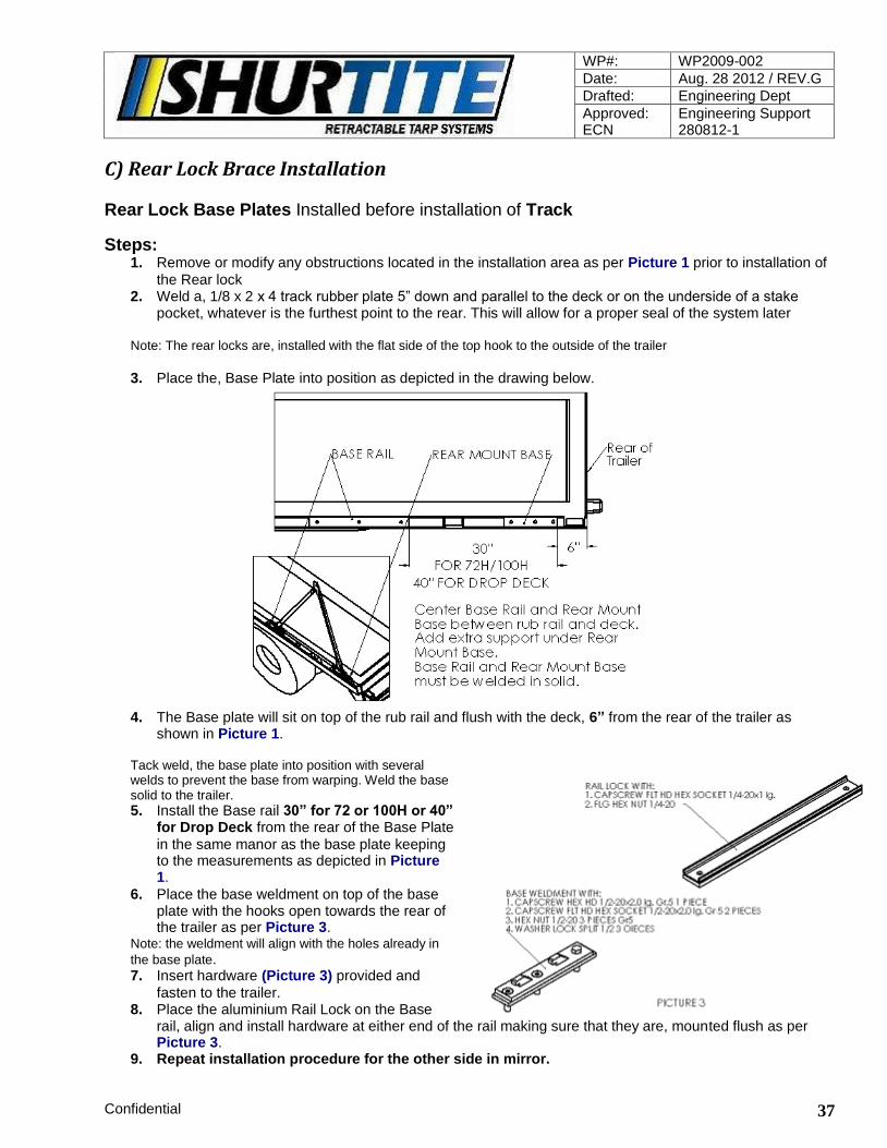
C) Rear Lock Brace Installation
Rear Lock Base Plates Installed before installation of Track
Steps: 1. Remove or modify any obstructions located in the installation area as per Picture 1 prior to installation of
the Rear lock 2. Weld a, 1/8 x 2 x 4 track rubber plate 5” down and parallel to the deck or on the underside of a stake
pocket, whatever is the furthest point to the rear. This will allow for a proper seal of the system later
Note: The rear locks are, installed with the flat side of the top hook to the outside of the trailer
3. Place the, Base Plate into position as depicted in the drawing below.
4. The Base plate will sit on top of the rub rail and flush with the deck, 6” from the rear of the trailer as
shown in Picture 1. Tack weld, the base plate into position with several welds to prevent the base from warping. Weld the base solid to the trailer. 5. Install the Base rail 30” for 72 or 100H or 40”
for Drop Deck from the rear of the Base Plate
in the same manor as the base plate keeping to the measurements as depicted in Picture 1.
6. Place the base weldment on top of the base plate with the hooks open towards the rear of the trailer as per Picture 3.
Note: the weldment will align with the holes already in
the base plate. 7. Insert hardware (Picture 3) provided and
fasten to the trailer. 8. Place the aluminium Rail Lock on the Base
rail, align and install hardware at either end of the rail making sure that they are, mounted flush as per Picture 3.
9. Repeat installation procedure for the other side in mirror.

WP#: WP2009-002
Date: Aug. 28 2012 / REV.G
Drafted: Engineering Dept
Approved: ECN
Engineering Support 280812-1
Confidential 38
C) Rear Lock Brace Installation 10. The lock bolt should be, installed on the rear bow as per Pictures 4 & 5.
11. Grease the aluminium Rail, the screw thread, and any moving parts of the rear lock
As per Picture 6
12. Install the rear lock and insert the lock pin to make sure that everything is, aligned correctly. 13. STROKE LIMITER CUTTING AND INSTALLATION (picture 6)
a. TENSION THE SYSTEM TO WHERE IT SHOULD BE b. MEASURE BETWEEN THE STOP COLLAR AND THE NUT c,. RELEASE THE SYSTEM d. UNSCREW THE NUT FROM THE FRONT OF THE ROD
e. SLIP THE CUT PIPE OVER THE ROD AND REATTACH THE NUT ASSEMBLY f. TENSION THE SYSTEM; IF THE STROKE LIMITER IS TOO LONG REMOVE IT AND CUT A LITTLE OFF. IF THE STROKE LIMITER IS TOO SHORT ADD A 1" SPACER OR, WHATEVER YOU NEED.

WP#: WP2009-002
Date: Aug. 28 2012 / REV.G
Drafted: Engineering Dept
Approved: ECN
Engineering Support 280812-1
Confidential 39
D) Rear Locks 1. With the front locks engaged and the rear locks fully released pull the tarp system to the back of the
trailer and hook the lock bolts on both sides with the hook at the top of the rear locks. 2. With the crank handle, tension one side 50% and then proceed to tension the other side 100% Return
to the starting side and tension 100%
Note: The tarp should be, tightened until the Rear Locks have moved the rear bow to approx. three inches from the rear of the trailer or continued tensioning is no longer possible; over time the tarp sections will stretch and the rear bow will travel an additional one inch
E) Wrinkles Steps:
1. Release the system 2. Mark the tarp with a temporary mark for reference and pull the wrinkle up over the top
Note: The wrinkle is a result of too much tension in the side panel; pulling the wrinkle up over the top does not actually move the wrinkle, it just relaxes the tarp; folds in the tarp that are a result of packaging and will relax with a few hot or sunny days
3. Tension the system and repeat if necessary

WP#: WP2009-002
Date: Aug. 28 2012 / REV.G
Drafted: Engineering Dept
Approved: ECN
Engineering Support 280812-1
Confidential 40
Track Installation 2
A) Air Deflector Steps:
1. The Air Deflector is, installed all the way up to the headboard wings (side frames) sliding into the wing extensions.
2. Install the air deflector until the rear is, reached, mark and cut the excess. 3. Repeat for the other side 4. Fasten the air deflector two inches from the end of the track with a 1/4” zip screw through the track into
the Air Deflector 5. Bolt the end of the deflector to the wing extension through the bottom with 5/16 carriage bolt RTC-12312.
The air deflector is installed after the Tarp Installation (page 28), Anchor Installation (page 29), Tensioning (page 31), and after Wrinkles (page 35)
Up-Lifters
A) Standard Lifters Note: The up-lifters push up in the middle but do not deform the corners of the tarp while tensioned; if the up lifters are too tight, permanent damage to the tarp could occur
One Piece lifters: install lifter into the Velcro on the
ceiling Hinged Lifters Steps:
1. Tension the system 2. Stand the lifters in on the track in the positions
where they are to be, installed. 3. Temporarily attach the Lifter Bracket to the Lifter
assembly with a clevis pin in the middle hole. (Note: the Two lifter bracket must be installed with the small space at the end of the hole pattern toward the sky)
4. Start with the second from the end intermediate lifter.
5. Install 4 lifter brackets without the cotter ring.

WP#: WP2009-002
Date: Aug. 28 2012 / REV.G
Drafted: Engineering Dept
Approved: ECN
Engineering Support 280812-1
Confidential 41
6. Hold all four lifter brackets up so the lifter is in contact (but not pushing) with the tarp at the upper tangent of the corners of the lifter on both sides.
7. Clamp the Two Lifter Brackets (at the bottom end) to the bow using the C-jaw vice-grip and measure the distance from the bow foot on both sides. See how the lifters sit on the tarps. Re-adjust and repeat if necessary. Note: The lifter legs can be, installed in any of the three holes provided
8. Try the next lifter at the same measurement as the first and repeat steps 4 to 7. After two lifters have been temporarily installed use the measurement for the remaining brackets making sure that the measurement will transfer for all. Note: All the lifter brackets are the approximate same height on all intermediate bows.
9. For the front and rear bows use the half brackets and continue with the same instructions except install the bolt with the head to the lifter leg.
10. With all the lifters in satisfactory positions, mark the position of the lifters and remove all of the pins, and sit them in the track. One Piece lifters remain hanging from the ceiling
11. Drill a 3/8 hole through the middle of the
bracket and through the tube. 12. Insert the hardware provided with the nuts
towards the front of the trailer. 13. Tighten and re-install the lifters. 14. Re-adjust any lifters that have moved 15. When all lifters are in position, install the
cotter rings into the clevis pins Note: Turn the clevis pins so that the holes face the front and the back of the trailer
B) Extra Lifters Installed in the same manner as One Piece Lifters above
Rear flap
A) Rear Flap Preparation Steps:
1. Place the back flap on a clean surface with the outside facing down 2. Grind the ends so that they are not sharp. Wrap duck tape around the ends to further protect the tarp and
to act as a barrier for contact with the aluminium. 3. Insert and center the round tube in the pocket above the vent. 4. Insert 2 rivets RTC-15071, one about 1 to 2 inches from each
end of the pocket, through the pocket into the tube. 5. Insert and center the square tube in the pocket at the bottom of
the flap. 6. Repeat step number 4.
Note. No fasteners are to be, installed through the rear flap itself.
7. Re-roll the flap for hanging.

WP#: WP2009-002
Date: Aug. 28 2012 / REV.G
Drafted: Engineering Dept
Approved: ECN
Engineering Support 280812-1
Confidential 42
B) Rear Flap Installation 1. Pulley equipped Rear Flap Only
1. Two 3/8 holes are needed in the top tube assembly. Drill the holes 28 inches in from both sides and a half-inch from the bottom of the tube.
2. Place the rope in through the hole towards the front of the system and knot. Continue with Rear Crank instructions
2. Rear Crank Equipped
1. Slide the top of the flap into the rear flap extrusion at the top of the bow The rear flap extrusion was installed during the Rear Bow Back Flap Extrusion (page 24)
2. Even out the flap on both sides and check the location of the tubes. Adjustment of the bottom tube may be required.
3. Fold the corner inside at a 45 deg. Angle so it is tangent to the bow corner. 4. Drill through the folded corner into the face of the bow corner place the rubber washer RTC-16014 on the
flap cover it with the steel washer RTC-14123 and insert rivet RTC-15071. 5. One rubber washer, steel washer and rivet per each corner.

WP#: WP2009-002
Date: Aug. 28 2012 / REV.G
Drafted: Engineering Dept
Approved: ECN
Engineering Support 280812-1
Confidential 43
C) Pulley and Rope installation Steps:
1. Mark the location for the pulley mounts on the rear flap. 2. Push the pulley hangers up against the rear flap extrusion. 3. The single pulley is located on the passenger side, and the two double pulleys are on the driver’s side. 4. Drill holes through the rear flap, and top tube to mount pulleys, two per pulley hanger. 5. Insert fasteners and tighten. 6. Run your rope from the backside installed during Rear Flap Installation (page 32) under the flap and
backup through the pulleys. 7. Wrap the rope three times around the rope hanger that was installed during
Rear Bow Flap Extrusion (page 19) Trim excess and tape together to make a loop to hook on the rope hanger.

WP#: WP2009-002
Date: Aug. 28 2012 / REV.G
Drafted: Engineering Dept
Approved: ECN
Engineering Support 280812-1
Confidential 44
D) Rear Flap Crank Installation and Operation Steps:
1. Take the handle of the rear crank and install the pivoting end onto it. 2. Drill through the pivoting end and fasten with the hardware provided. 3. Slide the pivoting end into the bottom steel tube of the flap 4. Drill through both the steel tube and the pivoting end with a ¼ bit 5. Insert the snap pin to secure the back flap to the crank 6. Standing to the side of the trailer roll the tarp up so that it is 80% to the top 7. With a push away from the rear and a twist of the handle swing the rolled up tarp onto the top of the rear
bow 8. Crank the handle until the flap is tight and secure
Note: The operation of the rear crank will become easier with practice; store the snap pin in the flap when not in use

WP#: WP2009-002
Date: Aug. 28 2012 / REV.G
Drafted: Engineering Dept
Approved: ECN
Engineering Support 280812-1
Confidential 45
E) Rear Flap Crank Holder Installation Steps:
DO NOT WELD THE HOLDER TO THE MAIN FRAME OF THE TRAILER
1. On the driver side find a location under the bed of the trailer to mount the crank holder
Note: The passenger side may be used as a mounting point only where there is no sufficient space to mount on the driver’s side
2. Clamp the tube into position on two cross members and insert the crank half way into the 2 x 2 tube
3. Holding the crank up against the cross members parallel to the side of the trailer locate the position of the pipe and clamp into position on a cross member
Note: adjustment of the tube may be required to allow proper positioning of the pipe. Attempt to remove the crank and re-insert
4. With the crank in both the tube and the pipe, mark the 2 x 2 angles position on two cross members close to center of the first bend of the handle and the 2 x 2 tube, then remove
5. Double check clearances for the handle by removing and re-inserting the handle into the holder
6. Remove the crank and weld all three items into position with welds on both sides
7. Re-insert the crank into the holder and this time you will have to slightly bend the crank in the middle to pass over the edge of the 2 x 2 angle and into the holder
8. Installing the bungee requires you to hook the handle near the first bend and mount the other end to a cross member. Mark the position and drill a 1/4 “ hole
9. Bend the hook closed on the cross member side to ensure that it is not lost
Note: the angle is mounted so that the crank will sit on top of the horizontal side with the vertical side welded to the cross members
WP#: WP2009-002
Date: Aug. 28 2012 / REV.G
Drafted: Engineering Dept
Approved: ECN
Engineering Support 280812-1
Confidential 46
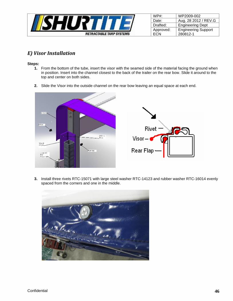
E) Visor Installation Steps:
1. From the bottom of the tube, insert the visor with the seamed side of the material facing the ground when in position. Insert into the channel closest to the back of the trailer on the rear bow. Slide it around to the top and center on both sides.
2. Slide the Visor into the outside channel on the rear bow leaving an equal space at each end.
3. Install three rivets RTC-15071 with large steel washer RTC-14123 and rubber washer RTC-16014 evenly spaced from the corners and one in the middle.

WP#: WP2009-002
Date: Aug. 28 2012 / REV.G
Drafted: Engineering Dept
Approved: ECN
Engineering Support 280812-1
Confidential 47
Snap Rivet to secure Visor ends at installation
Tools: Ø5/16 drill Procedure steps: Rear flap and pulleys must already be, installed.
4. Measure approximately 3/4" from the top edge down of the angle and the outside edge in and drill a Ø
5/16 through the over 90 bar angle. 5. Push the end of the Visor up to the angle and make a small hole through the Visor in line with the Ø5/16
hole. 6. Insert the female half of the snap rivet into the Ø 5/16 hole from the inside out.
` 7. Push the male half of the snap rivet through the small hole in the end of the visor from the outside in, and
push it through the female half of the snap rivet.
8. Repeat steps 4 to 6 for the other end.

WP#: WP2009-002
Date: Aug. 28 2012 / REV.G
Drafted: Engineering Dept
Approved: ECN
Engineering Support 280812-1
Confidential 48
Locks and Handles
A) Safety Clip Steps:
1. Lock the front locks 2. Make sure front lock handles are fully engaged 3. Insert Safety Clip through the Ø3/16 hole through the link and handle from the outside in. 4. Insert the loose end of the tether through the crimp and through the lower hole in the link. 5. Wrap the loose end around the back of the link into the crimp. 6. Repeat for other side 7. Do not tension the system unless the safety clip has been installed.
B) Strap Handle Installation Front bow Steps:
1. Insert the Strap Handle into the tarp holder 2. Slide the handle up until the handle part itself is able to fold easily in front of the foot and in-between the
“D” foam seal of the headboard. 3. Rivet the handle into place through one wall of the tarp holder.

WP#: WP2009-002
Date: Aug. 28 2012 / REV.G
Drafted: Engineering Dept
Approved: ECN
Engineering Support 280812-1
Confidential 49
Rear Bow Steps:
1. Insert the Strap Handle into the tarp holder. 2. Slide the handle up until the handle part itself is able to fold easily into the space between the foot and the
handle
3. Rivet the handle into place through one wall of the tarp holder.
Drop Deck Installation
A) Trailer Deck preparation Steps:
1. Follow steps outlined in Trailer Deck preparation A),B) section page 4 and 5 for both the upper and
lower track installation. 2. Add shims 3/8 to 1/2” behind the track at the wheel openings if the opening is less then 8” from the top of
the deck so the tires do not contact the air deflector. Add only enough shim to clear the tires. 3. Do not weld the corner build-out caps on at the deck drop area 4 corners. 4. Position and weld into place the 2x6 drop spacer channels

WP#: WP2009-002
Date: Aug. 28 2012 / REV.G
Drafted: Engineering Dept
Approved: ECN
Engineering Support 280812-1
Confidential 50
`
5. Insert the white nylon track insert in the upper track all the way up to the headboard side frame and temporally hold with vice grip.
6. From underneath the track Drill a Ø 9/32 hole up through the center of the nylon insert and insert a 1/4” flat head screw down through the hole and fasten with a nut so the screw head is flush with the insert.
7. Insert the white nylon track insert in the lower track flush to the track ends and temporally hold with vice grip.

WP#: WP2009-002
Date: Aug. 28 2012 / REV.G
Drafted: Engineering Dept
Approved: ECN
Engineering Support 280812-1
Confidential 51
8. Repeat step 5 for the lower track insert at the drop end. 9. For the lower track back end; drill a clearance hole for a 3/8 bolt through the track from top to bottom
passing through the center of the white nylon insert approximately one inch from the end of the track and insert the bow stopper bolt assembly. Trim excess.
10. Repeat for the other side. 11. Install the bow 1-3/4” wheel guide at the drop.
Tools: Ø3/8 drill, wrench
steps: a) Install the corner build-out boxes without the cover on
the upper and lower deck. The cover will be, installed later.
b) Mount the upper and lower track. c) Position the wheel guide so it is in line with the 1-3/4”
wheel channel on the track and flush with the top of the track and mark the location for the 2 holes.
d) Drill two Ø13/32 holes through the corner build-out. e) Insert the 3/8-16x1-1/8” lg. bolts with the heads toward
the rear of the trailer and fasten with the 3/8 flange nut. f) Repeat for opposite side, and weld on the Build-out cap.

WP#: WP2009-002
Date: Aug. 28 2012 / REV.G
Drafted: Engineering Dept
Approved: ECN
Engineering Support 280812-1
Confidential 52
12. Install bows 13. Install Tarp sections as described in Tarp and Tarp holder installation section. (page 26, 28) Refer to diagram on page 28
14. Measure between the bottom of the upper track nylon insert and the deck and cut 2 pieces of track rubber at the measured length.
15. Move the drop bow to the drop area so approximately 6” of the foot covers the drop area. 16. Push the measured piece of track rubber tight to the foot. 17. Attach the track rubber to the drop face with rivets and the 1-1/4 wide x 1/8 thick aluminium strips. 18. Cut a slit in the rubber just above the bow lock mount with a razor knife. This will allow the bow lock to
slip past the rubber seal. 19. Insert the Air Deflector and secure with zip screws at the ends of the track, two at the end of the upper
track, and four places on the lower track.

WP#: WP2009-002
Date: Aug. 28 2012 / REV.G
Drafted: Engineering Dept
Approved: ECN
Engineering Support 280812-1
Confidential 53
Install Procedure-Drop Doors
Steps:
1. Insert the edge of the drop door with the plastic tube into the empty channel from the bottom of the tarp holder so the cargo strap reinforcement is at the bottom and facing in when the door is closed.
2. Fasten with two rivets; one 2 inches below the top and one 1 inch above the curve in the tarp holder. 3. Pull the flap around the front of the drop opening and check location of bungee anchors. 4. Drill holes and mount the eye bolts supplied 5. Secure the flap with the bungees 6. Open the flap and fold it back so it sits flat to the bow foot 7. Fasten the male buckle strap to the bow foot with rivets. This is to hold the door open while moving the
system from back to front.

WP#: WP2009-002
Date: Aug. 28 2012 / REV.G
Drafted: Engineering Dept
Approved: ECN
Engineering Support 280812-1
Confidential 54
C) Piggy Back Installation The tarp sections should, already be, installed.
Steps: Refer to the piggy back set-up diagram on page 56
1. Install the tarp and up-lifters first.

WP#: WP2009-002
Date: Aug. 28 2012 / REV.G
Drafted: Engineering Dept
Approved: ECN
Engineering Support 280812-1
Confidential 55
2. Move the drop bow onto the upper deck. 3. Clamp the piggy back tongue, onto the drop bow with vice grips. 4. Align the front bow support with the tongue so that the tongue when inserted will lift the front bow slightly
but not enough to bind the wheels. 5. Drill the holes for, and mount the tongue with the spacer behind the tongue. 6. Weld the front bow support to the front bow. 7. Place the intermediate bow support over the tongue and lift the intermediate bow slightly, but not enough
to bind the wheels, and mount the intermediate bow support so the top inside is tight to the top of the tongue.
8. Clamp in place, and drill the holes and fasten with bolts. 9. Mount the guide tongue as per the diagram below.
10. Align the ground closing lock pin with the notch in the piggy back tongue through the front bow support, and drill 4 holes the bow spacer plate and fasten with bolts and nuts. The ground closing lock is mounted on the outside of the bow spacer plate.
Helpful hints:
1. Be sure to protect the tarp when welding front bow support. 2. Use a pry bar, to gently, lift the bows slightly. 3. The top and bottom rails should overlap by 6 inches.

WP#: WP2009-002
Date: Aug. 28 2012 / REV.G
Drafted: Engineering Dept
Approved: ECN
Engineering Support 280812-1
Confidential 56

WP#: WP2009-002
Date: Aug. 28 2012 / REV.G
Drafted: Engineering Dept
Approved: ECN
Engineering Support 280812-1
Confidential 57
Front End Build Out 8” installation procedure - Optional
Tools: Drill, Clamps, Wrench, Impact Driver
Drawing: RTC-01300 Rev. B
Steps: Trailer Preparation
1. Remove all lighting around the front of the trailer. Be sure the wiring is out of the way and not
resting on any metal parts that will become heated due to welding.
2. Remove rub rail and pockets 24 inches back measured from the front of the trailer. 3. Remove glad-hands, glad-hand connections, and electrical connections.
4. Prepare the front and sides for welding.
.
Steps: Install Front Build-out parallel to the front and flush with top of deck.
1. Review assembly diagram before starting built-out installation.
2. Weld Side Extensions (RTC-01309) to trailer with the angled end measuring 8 inches from the
front of the trailer.

WP#: WP2009-002
Date: Aug. 28 2012 / REV.G
Drafted: Engineering Dept
Approved: ECN
Engineering Support 280812-1
Confidential 58
3. Fit the notched end of the Front Mount (RTC-01301 and RTC-01302) into the Side Extensions
with notch up and top surface flush with Side Extensions. Weld to trailer and install bolts and
nuts. 4. Position and tack in place the Middle Support (RTC-01305 and RTC-01306).
5. Position and tack in place the End Support (RTC-01303 and RTC-01304) aligning the angled
ends with the Front Mount.
6. Fit the Front Build-out Cap (RTC-01308) between the Side Extensions and tack the corners
together.
7. Insure all of the parts are square and flush to the trailer and weld around all mating ends.
8. Drill holes and install the Corner Angle Support (RTC-01313)

WP#: WP2009-002
Date: Aug. 28 2012 / REV.G
Drafted: Engineering Dept
Approved: ECN
Engineering Support 280812-1
Confidential 59
9. Install the Air Extension Kit (RTC-08075), and attach glad-hands and electrical connection to the Glad-Hand Mount Plate (RTC-01314).
10. Fasten the Glad-Hand Mount Plate to the Front Build-out Cap with 6 bolts and nuts.
11. Weld End Caps to Side Extensions.
Rear Step Installation- Optional
Steps:
1. Position the top of the step 3" down from rear sill and 4" from outside of trailer (depends on rear features of each trailer).
2. Mark and cut the step frame to fit square it on all sides and clamp or tack it into place. 3. Open the step and check that the outside edge looks square to the rear sill and the bumper. 4. Square the top of the step to the step frame. 5. Weld frame into place. 6. Weld 1/4 x 2 x 2 gussets to reinforce the step frame where it connects to the trailer,if it is necessary.

WP#: WP2009-002
Date: Aug. 28 2012 / REV.G
Drafted: Engineering Dept
Approved: ECN
Engineering Support 280812-1
Confidential 60
Tarp Repair
Steps:
1. Cut a piece of tarp 1-1/2” per side larger than the area of repair. 2. Use a flat firm surface behind the area that needs to be, repaired. Set the heat gun to 3/4 heat setting 3. Insert the end of the gun between the two pieces of tarp. Starting from the middle of the tarp, heat the
material and use the roller to seal the material. Work from center to the outside edges. Use the roller to smooth out edges. Adjust heat accordingly.
Final Testing and Sealing
A) Functional Testing The trailer must be, cleaned off and the track free of debris Steps:
1. Roll the system from all four corners to ensure smooth operation. 2. Open and close the system without tensioning another three to four times to help train the tarp. 3. Lock the front locks and tension the system.

WP#: WP2009-002
Date: Aug. 28 2012 / REV.G
Drafted: Engineering Dept
Approved: ECN
Engineering Support 280812-1
Confidential 61
B) Sealing the System Silicone the outside of the headboard only after all previous steps have been, performed. The silicone will
need time to dry before releasing the tension Steps:
1. Headboard
Steel Trailers: seal the front edge of the base plate all the way across the front and sides Front- Silicone:
Along all seams outside the headboard
Underneath where the air deflector meets the wing extension
Where the track meets the build out
Where the track rubber ends and the rivets are exposed
Any other place that air could enter the system Rear- Silicone
around and under the rear pockets
Where the track rubber ends and the rivets are exposed
and any other place that air could enter the system
Sticker Location: Place stickers as shown Extra yellow and blue stickers applied to inside of headboard. stickers one per each side.

WP#: WP2009-002
Date: Aug. 28 2012 / REV.G
Drafted: Engineering Dept
Approved: ECN
Engineering Support 280812-1
Confidential 62
Nut and Bolt Torque Specifications MAGNUM Tarp System Tightening torque suggested for fasteners on bow corners and feet. Torque values listed are from bolt suppliers catalogue, and actual past foot assemblies. Bow Corners Part Number 4500-500-012, 4500-500-014 3/8-16 Nylon insert lock nut, type NE GR 5 zinc coated Tighten to 30-35 ft.-lb’s Bow Corners to Top and Side Tube Part Number 4500-500-012, 4500-500-014 3/8-16 Nylon insert lock nut, type NE GR 5 zinc coated Tighten to 30-35 ft.-lb’s Bow Top and Side Spacer angle plate Part Number 4500-500-012, 4500-500-015 3/8-16 Nylon insert lock nut, type NE GR 5 zinc coated Tighten to 30-35 ft.-lb’s Two Lifter Bracket to Bow Tube Part Number 5000-200-013, 5000-200-011 5/16-18 Hex Nut GR 5 zinc coated Tighten to 20-25 ft.-lb’s
3” wheel Axle to foot frame (3/4-16) Part Number 4500-500-005
3/4-16
Nylon insert lock nut, type NTE GR 5 zinc coated
Tighten to 100-110 ft.-lb’s

WP#: WP2009-002
Date: Aug. 28 2012 / REV.G
Drafted: Engineering Dept
Approved: ECN
Engineering Support 280812-1
Confidential 63
TRAINING CHECK LIST
Headboard
Mounting front side build-outs DS/PS Levelling headboard Bolting the headboard Welding headboard Installing side frames and front locks Wiring Headboard final assembly
Bow Assembly
Front bow assembly Intermediate bow assembly Rear bow assembly Torque for cast corner bolts
Rear Pockets and Posts
Removal of rub-rail and stake pockets Measuring & installing rear pockets Install track rubber tabs & safety chains Installation of ratchets Alignment of hooks Alignment of combo hooks
Lock Brace
Install Rear Mount Install forward Guide Adjust Stroke Limiter Remove from trailer
Track
Installation of track tabs Measuring and cutting track Installation of track rubber Mounting and levelling track Drilling and bolting track Installation of the track insert Installation of the 3” hole and stop block
Lifters
Installation of lifter brackets Installation of lifters Alignment of lifter brackets Installation of extra lifters
Tarp
Installation of the tarp panels Installation of the tarp holders at the bow feet Tensioning the system Levelling the tarp panels Installation of the Air deflector Installation of up-lifters
Extras
Chain box and dunage rack installation Man door tray installation Internal lights installation Rear step installation Installing tarp handles
Rear Flap
Installation of the rear flap Installation of the tubes in rear flap Installation of the visor Installation of a crank or rope and pulley Installation of a crank holder
Note for Dealers: Installation employees must be trained by ShurTite/Roll-Tite before installing any tarp system independently. By signing this form, you agree that you have been fully trained and understand all of the installation and assembly processes of the Magnum system and any issues, as a result, of installation process are solely the responsibility of the dealer. Name of Trainee (Print) Dealer: Signature Date: Name of Trainer (Print) Dealer: Signature Date:

WP#: WP2009-002
Date: Aug. 28 2012 / REV.G
Drafted: Engineering Dept
Approved: ECN
Engineering Support 280812-1
Confidential 64
In House System Discharge and Quality Checklist Date:_____________ Customer:_____________________ VIN#:________________________ System size:___________________ R-T serial #:___________________ Inspector:_____________________ Approved:_______________________ It is the responsibility of the employee (Inspector) to check the system to ensure all items listed below are satisfactory to ShurTite/Roll-Tite’s standard of quality. It is the responsibility of the Production Manager, Service Manager, Branch Manager or acting supervisor (Approved) to ensure the trailer and system are safe to travel and all standards of quality are met.
NOTE: A trailer and system must not leave the premises without an approved signature.
Headboard:
The front door opens and closes properly and locking mechanism functions correctly.
Latching mechanism between headboard and tarpaulin operates smoothly.
All seals are in place including silicone between headboard and trailer.
Inspect bolt pattern and ensure bolts are tightened to specification.
Track / Rails:
Track is installed properly with correct hardware. Hole drilled for wheel service.
Track stop-bolts installed at rear on both sides.
Lights have been lowered (if required) and replaced at the front and rear. No hanging wires.
Track guard is in place in the headboard.
Rails have been cleaned and are free from debris.
Tarpaulin, Bows and Lifters:
Inspect tarpaulin for pin holes, quality of bar seals and graphics.
Check Velcro is sealed around lifters.
Ensure reinforcements are protecting tarp from wear.
Check all bolts are tightened to proper specifications.
Ensure all bow corners have been sealed.
Lifters are centered and attached properly.
Check overall height of system is within the 162” maximum for US systems.
Rear of System:
Steps installed if requested.
Tensioning system operates smoothly/ Rear Lock Braces are greased.
Rope and Pulleys and Rear Flap fit correctly and securely behind lock bars and operate smoothly.
Rear crank (if requested) operates properly and has mounting brackets installed.
Overall:
The tarpaulin has been trained by opening and closing the system a minimum of 5 times.
Wheels roll smoothly inside track.
All trailer lights, air-lines and landing gear function as originally intended.
All moving parts have been lubricated.
Clean track and trailer deck inside/outside of tarpaulin.

WP#: WP2009-002
Date: Aug. 28 2012 / REV.G
Drafted: Engineering Dept
Approved: ECN
Engineering Support 280812-1
Confidential 65
Review with customer upon delivery of Tarping System
Check list must be, signed, dated, and faxed to, ShurTite/Roll-Tite, upon completion for warranty
to take effect. Fax: 519-751-3997
Inspection and Tarp System Operation Tarp quality
Front Bow to Headboard seal
Lifters
System rolls freely
Tail flap
Track rubber seals to bottom of trailer
Tensioning Device
Comments:
Customer agrees all as above are in good order and quality that meets or exceeds customer expectations and requirements. Customer, has been instructed, on how to operate, and maintain the system.
Employee Name (print):
Employee Signature (sign):
Date of Delivery (dd/mm/yy):
Trailer Owner or owner representative (print):
Trailer Owner or owner representative (sign):
Trailer Owner contact information
Phone, Fax, E-mail,
V.I.N. number of trailer:
ShurTite/Roll-Tite Serial Number:

WP#: WP2009-002
Date: Aug. 28 2012 / REV.G
Drafted: Engineering Dept
Approved: ECN
Engineering Support 280812-1
Confidential 66
Inspection and Maintenance ShutTite/Roll-Tite Magnum Tarp Systems
Customer Copy Note: New systems must be checked after first 6 months and 1 year of operation at the installation shop
(ShurTite/Roll-Tite dealer) with no charge.
Criteria:
1. The system must always be kept tight when trailer is in motion. Running with the system loose will cause premature wear on the system.
2. The system must not be over tightened. Always use the manufacture’s devices to tighten the system.
3. The rear flap must always be secured in the down position. It is recommended not to run with the rear flap in the up position.
4. The tarpaulin material should only be washed with soap and water. No acid, wax or harsh chemicals should ever be used to clean the tarp.
5. If you have a small rip, hole or other tarp issues, have it properly repaired (or the section replaced) by ShurTite/Roll-Tite service professional.
Daily Inspection Schedule:
1. Be sure the front lock is in the locked position with the safety clip in place.
2. Inspect the tether that the safety clip is attached to. The safety clip must always be in place before the system is tensioned (closed).
3. Release the rear tensioning device, unlock the front and check the latch hooks for cracks.
4. Inspect the rear tensioning system including the crank and crank holder for cracks or breaks. Grease the screw (winding brace) and moving parts when they appear dry.
5. Check for wear or fraying on the ratchet straps. If straps show signs of wear replace at once.
6. Check to be sure the rear flap is down and secure.
7. The tarp should appear smooth and tight.
8. Be sure crank and or rope are secure.
WP#: WP2009-002
Date: Aug. 28 2012 / REV.G
Drafted: Engineering Dept
Approved: ECN
Engineering Support 280812-1
Confidential 67
Monthly Inspection Schedule: In addition to daily inspection perform the following:
1. From inside of the trailer:
a. Check the seal between the headboard and the front bow. There should be no light showing through.
b. Visually check and also touch all nuts and bolts on bows and feet to see if any have come loose or are missing.
2. Inspect all the wheels (large and small) to be sure they rotate freely. Damaged or seized wheels should be replaced as soon as possible.
3. Inspect the tarp for wear and or small rips or holes. If any are found, have the tarp repaired at once.
4. Check the rear tensioning system for cracks or breaks and grease the screw (winding brace) and moving parts when they appear dry.
5. Check the winding brace crank for cracks. Replace or repair at once.
6. For crank operated rear flap: check the crank and crank holder for cracks and the universal joint should be free running. If not then apply oil or grease.
7. For rope and pulley system: the rope should not be, frayed or, have cuts. The rope must always be properly stored.
8. The pulleys should swivel and roll freely.
9. Check the up-lifter assemblies to be sure the assembly is intact.
10. Inspect both inside and outside of the rear flap for damage.
11. Visually check for cracks at any of the welded areas on and around the headboard both inside and out.
12. Check for cracks around the floor bolts that mount the headboard (inside trailer).
13. Ensure the track has not come loose and all the bolts are in place.
14. Report immediately to the specialized ShurTite/Roll-Tite shop any suspected concerns or irregularities with your system.

WP#: WP2009-002
Date: Aug. 28 2012 / REV.G
Drafted: Engineering Dept
Approved: ECN
Engineering Support 280812-1
Confidential 68
SAFETY ALERT
Memorandum
To: Dealers and End Users
CC:
From: ShurTite/Roll-Tite
Date: 18/08/2014
Re: Safety Alert (SA 2009 – 01)
SAFETY ALERT
It is imperative to ensure the Safety Clips (PN 800-07-72-357) on Magnum systems are securely in place
when the front lock assemblies are engaged. Failure to do so could result in the lock opening, which may cause the tarp system to disengage from the trailer.
Inspection of the Safety Clip assembly must be part of your regular daily maintenance and circle check procedures. DO NOT operate the trailer without the lock and Safety Clip securely in place.
Contact your authorized dealer if you have any questions or are in need of Safety Clip Assemblies.


![[Michael Shur] Physics of Semiconductor Devices(Bookos.org)](https://static.documents.pub/doc/80x56/55cf937e550346f57b9da621/michael-shur-physics-of-semiconductor-devicesbookosorg.jpg)


