28
PWCBRD-10-IA-en-14 | Version 1.4 ENGLISH Installation Manual SMA POWER CONTROL MODULE

PWCBRD-10-IA-en-14 | Version 1.4 ENGLISH
Installation ManualSMA POWER CONTROL MODULE

Legal Provisions SMA Solar Technology AG
2 PWCBRD-10-IA-en-14 Installation Manual
Legal ProvisionsThe information contained in this document is the property of SMA Solar Technology AG. Publishing its content, either partially or in full, requires the written permission of SMA Solar Technology AG. Any internal company copying of the document for the purposes of evaluating the product or its correct implementation is allowed and does not require permission.
SMA WarrantyYou can download the current warranty conditions from the Internet at www.SMA-Solar.com.
TrademarksAll trademarks are recognized, even if not explicitly identified as such. A lack of identification does not mean that a product or symbol is not trademarked.The BLUETOOTH® word mark and logos are registered trademarks owned by Bluetooth SIG, Inc. and any use of these marks by SMA Solar Technology AG is under license.Modbus® is a registered trademark of Schneider Electric and is licensed by the Modbus Organization, Inc.QR Code is a registered trademark of DENSO WAVE INCORPORATED.Phillips® and Pozidriv® are registered trademarks of Phillips Screw Company.Torx® is a registered trademark of Acument Global Technologies, Inc.
SMA Solar Technology AG Sonnenallee 1 34266 Niestetal GermanyTel. +49 561 9522-0 Fax +49 561 9522-100 www.SMA.de E-mail: [email protected]© 2004 to 2014 SMA Solar Technology AG. All rights reserved.

SMA Solar Technology AG Table of Contents
Installation Manual PWCBRD-10-IA-en-14 3
Table of Contents1 Information on this Document. . . . . . . . . . . . . . . . . . . . . . . . . . . 5
1.1 Validity. . . . . . . . . . . . . . . . . . . . . . . . . . . . . . . . . . . . . . . . . . . . . . . . . 51.2 Target Group. . . . . . . . . . . . . . . . . . . . . . . . . . . . . . . . . . . . . . . . . . . . 51.3 Additional Information . . . . . . . . . . . . . . . . . . . . . . . . . . . . . . . . . . . . . 51.4 Symbols . . . . . . . . . . . . . . . . . . . . . . . . . . . . . . . . . . . . . . . . . . . . . . . . 51.5 Typography . . . . . . . . . . . . . . . . . . . . . . . . . . . . . . . . . . . . . . . . . . . . . 61.6 Nomenclature . . . . . . . . . . . . . . . . . . . . . . . . . . . . . . . . . . . . . . . . . . . 6
2 Safety . . . . . . . . . . . . . . . . . . . . . . . . . . . . . . . . . . . . . . . . . . . . . . 72.1 Appropriate Usage . . . . . . . . . . . . . . . . . . . . . . . . . . . . . . . . . . . . . . . 72.2 Safety Precautions . . . . . . . . . . . . . . . . . . . . . . . . . . . . . . . . . . . . . . . . 82.3 Supported Products . . . . . . . . . . . . . . . . . . . . . . . . . . . . . . . . . . . . . . . 9
3 Scope of Delivery . . . . . . . . . . . . . . . . . . . . . . . . . . . . . . . . . . . . 104 Product Description . . . . . . . . . . . . . . . . . . . . . . . . . . . . . . . . . . 11
4.1 SMA Power Control Module . . . . . . . . . . . . . . . . . . . . . . . . . . . . . . . 114.2 Type Label . . . . . . . . . . . . . . . . . . . . . . . . . . . . . . . . . . . . . . . . . . . . . 12
5 Electrical Connection . . . . . . . . . . . . . . . . . . . . . . . . . . . . . . . . . 135.1 Mounting Position and Cable Route . . . . . . . . . . . . . . . . . . . . . . . . . 135.2 Installing the Module . . . . . . . . . . . . . . . . . . . . . . . . . . . . . . . . . . . . . 145.3 Connecting the Ripple Control Receiver . . . . . . . . . . . . . . . . . . . . . . 155.4 Information on Module Configuration . . . . . . . . . . . . . . . . . . . . . . . . 19
6 Troubleshooting . . . . . . . . . . . . . . . . . . . . . . . . . . . . . . . . . . . . . 207 Decommissioning . . . . . . . . . . . . . . . . . . . . . . . . . . . . . . . . . . . . 21
7.1 Removing the Module . . . . . . . . . . . . . . . . . . . . . . . . . . . . . . . . . . . . 217.2 Packing the Module for Shipment . . . . . . . . . . . . . . . . . . . . . . . . . . . 227.3 Disposing of the Module . . . . . . . . . . . . . . . . . . . . . . . . . . . . . . . . . . 22
8 Technical Data . . . . . . . . . . . . . . . . . . . . . . . . . . . . . . . . . . . . . . 239 Contact . . . . . . . . . . . . . . . . . . . . . . . . . . . . . . . . . . . . . . . . . . . . 24

Table of Contents SMA Solar Technology AG
4 PWCBRD-10-IA-en-14 Installation Manual
SMA Solar Technology AG 1 Information on this Document
Installation Manual PWCBRD-10-IA-en-14 5
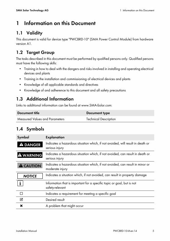
1 Information on this Document1.1 ValidityThis document is valid for device type "PWCBRD-10" (SMA Power Control Module) from hardware version A1.
1.2 Target GroupThe tasks described in this document must be performed by qualified persons only. Qualified persons must have the following skills:
• Training in how to deal with the dangers and risks involved in installing and operating electrical devices and plants
• Training in the installation and commissioning of electrical devices and plants• Knowledge of all applicable standards and directives• Knowledge of and adherence to this document and all safety precautions
1.3 Additional InformationLinks to additional information can be found at www.SMA-Solar.com:
1.4 Symbols
Document title Document typeMeasured Values and Parameters Technical Description
Symbol ExplanationIndicates a hazardous situation which, if not avoided, will result in death or serious injuryIndicates a hazardous situation which, if not avoided, can result in death or serious injuryIndicates a hazardous situation which, if not avoided, can result in minor or moderate injuryIndicates a situation which, if not avoided, can result in property damage
Information that is important for a specific topic or goal, but is not safety-relevant
☐ Indicates a requirement for meeting a specific goal☑ Desired result✖ A problem that might occur
1 Information on this Document SMA Solar Technology AG
6 PWCBRD-10-IA-en-14 Installation Manual
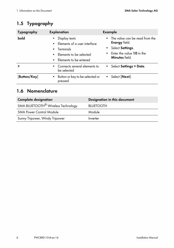
1.5 Typography
1.6 Nomenclature
Typography Explanation Examplebold • Display texts
• Elements of a user interface• Terminals• Elements to be selected• Elements to be entered
• The value can be read from the Energy field.
• Select Settings.• Enter the value 10 in the
Minutes field.
> • Connects several elements to be selected
• Select Settings > Date.
[Button/Key] • Button or key to be selected or pressed
• Select [Next].
Complete designation Designation in this documentSMA BLUETOOTH® Wireless Technology BLUETOOTHSMA Power Control Module ModuleSunny Tripower, Windy Tripower Inverter
SMA Solar Technology AG 2 Safety
Installation Manual PWCBRD-10-IA-en-14 7
2 Safety2.1 Appropriate UsageThe SMA Power Control Module is a multifunction interface which enables grid management services to be implemented for one inverter.The module is available as a retrofit kit or is pre-installed in the inverter.The inverter still complies with the standard after the product has been installed.The module may be used in parallel with the multifunction relay in the inverter. If you want to use the module at the same time as the multifunction relay in the inverter, you must ensure that no more than 30 V DC or 25 V AC are connected to the multifunction relay.The relays of the ripple control receiver may only be supplied by the 12 V output of the module. Do not supply the relays of the ripple control receiver with any other voltage sources.Use this module only in accordance with the enclosed documentation and with the locally applicable standards and directives. Any other use can result in personal injury or property damage.For safety reasons, it is not permitted to modify the product or install components that are not explicitly recommended or distributed by SMA Solar Technology AG for this product.The type label must be permanently attached to the product.The enclosed documentation is an integral part of this product.
• Read and observe the documentation.• Keep the documentation in a convenient place for future reference.

2 Safety SMA Solar Technology AG
8 PWCBRD-10-IA-en-14 Installation Manual
2.2 Safety PrecautionsThis section contains safety precautions that must be observed at all times when working on or with the product. To prevent personal injury or property damage and to ensure long-term operation of the product, read this section carefully and follow the safety precautions at all times.
Danger to life due to electric shock when opening the inverterHigh voltages are present in the live components of the inverter. Touching live components results in death or serious injury.
• Prior to performing any work on the inverter, always disconnect the inverter from all voltage sources on the AC and DC sides (see inverter installation manual). Observe the waiting time to allow the capacitors to discharge.
Risk of burns due to hot enclosure partsSome parts of the inverter enclosure can get hot during operation. Touching these enclosure parts can result in burn injuries.
• Do not touch any parts other than the lower enclosure lid of the inverter during operation.
Damage to the inverter due to electrostatic dischargeThe internal components of the inverter can be irreparably damaged by electrostatic discharge.
• Earth yourself before touching any inverter component.
SMA Solar Technology AG 2 Safety
Installation Manual PWCBRD-10-IA-en-14 9
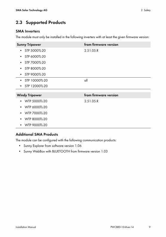
2.3 Supported ProductsSMA InvertersThe module must only be installed in the following inverters with at least the given firmware version:
Additional SMA ProductsThe module can be configured with the following communication products:
• Sunny Explorer from software version 1.06• Sunny WebBox with BLUETOOTH from firmware version 1.03
Sunny Tripower from firmware version• STP 5000TL-20 2.51.05.R• STP 6000TL-20• STP 7000TL-20• STP 8000TL-20• STP 9000TL-20• STP 10000TL-20• STP 12000TL-20
all
Windy Tripower from firmware version• WTP 5000TL-20 2.51.05.R• WTP 6000TL-20• WTP 7000TL-20• WTP 8000TL-20• WTP 9000TL-20
3 Scope of Delivery SMA Solar Technology AG
10 PWCBRD-10-IA-en-14 Installation Manual
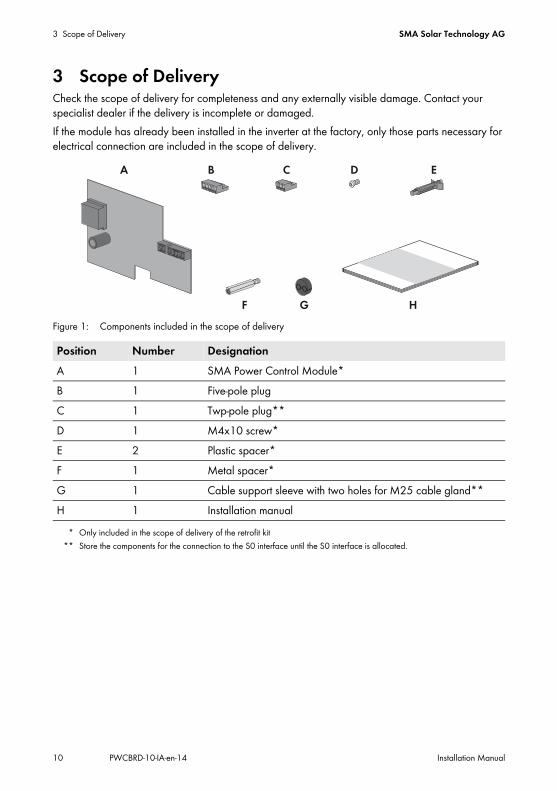
3 Scope of DeliveryCheck the scope of delivery for completeness and any externally visible damage. Contact your specialist dealer if the delivery is incomplete or damaged.If the module has already been installed in the inverter at the factory, only those parts necessary for electrical connection are included in the scope of delivery.
Figure 1: Components included in the scope of delivery
Position Number DesignationA 1 SMA Power Control Module*
* Only included in the scope of delivery of the retrofit kit
B 1 Five-pole plugC 1 Twp-pole plug**D 1 M4x10 screw*E 2 Plastic spacer*F 1 Metal spacer*G 1 Cable support sleeve with two holes for M25 cable gland**
** Store the components for the connection to the S0 interface until the S0 interface is allocated.
H 1 Installation manual

SMA Solar Technology AG 4 Product Description
Installation Manual PWCBRD-10-IA-en-14 11
4 Product Description4.1 SMA Power Control ModuleThe SMA Power Control Module is a multifunction interface which enables grid management services to be implemented for one inverter.For the implementation of grid management services, the module receives the specifications of the network operator via a ripple control receiver.The module can convert the active power limitation in staged intervals of 0%, 30%, 60% and 100% of the agreed connected load.
Figure 2: Design of the SMA Power Control Module
Position DesignationA Holes for attachment with plastic spacersB Socket for connecting to the S0 interface*
* The S0 interface is not allocated.
C Socket for connecting the ripple control receiverD Hole for attachment with the metal spacerE Type label

4 Product Description SMA Solar Technology AG
12 PWCBRD-10-IA-en-14 Installation Manual
4.2 Type LabelThe type label clearly identifies the product. The type label is located on the front of the product.
Figure 3: Layout of the type label (example)
You will require the information on the type label to use the product safely and when seeking customer support from the SMA Service Line.
Position Designation ExplanationA FA Number of the production orderB ‒ Hardware versionC ‒ Device typeD SER Serial number
SMA Solar Technology AG 5 Electrical Connection
Installation Manual PWCBRD-10-IA-en-14 13
5 Electrical Connection5.1 Mounting Position and Cable Route
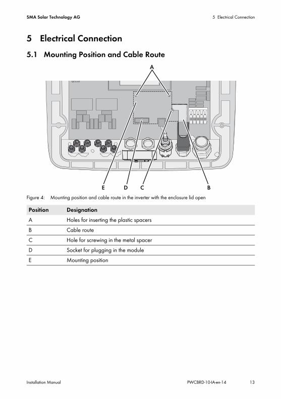
Figure 4: Mounting position and cable route in the inverter with the enclosure lid open
Position DesignationA Holes for inserting the plastic spacersB Cable routeC Hole for screwing in the metal spacerD Socket for plugging in the moduleE Mounting position
5 Electrical Connection SMA Solar Technology AG
14 PWCBRD-10-IA-en-14 Installation Manual
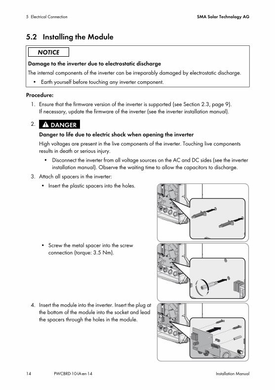
5.2 Installing the Module
Procedure:1. Ensure that the firmware version of the inverter is supported (see Section 2.3, page 9).
If necessary, update the firmware of the inverter (see the inverter installation manual).
3. Attach all spacers in the inverter:• Insert the plastic spacers into the holes.
• Screw the metal spacer into the screw connection (torque: 3.5 Nm).
4. Insert the module into the inverter. Insert the plug at the bottom of the module into the socket and lead the spacers through the holes in the module.
Damage to the inverter due to electrostatic dischargeThe internal components of the inverter can be irreparably damaged by electrostatic discharge.
• Earth yourself before touching any inverter component.
2.Danger to life due to electric shock when opening the inverterHigh voltages are present in the live components of the inverter. Touching live components results in death or serious injury.
• Disconnect the inverter from all voltage sources on the AC and DC sides (see the inverter installation manual). Observe the waiting time to allow the capacitors to discharge.

SMA Solar Technology AG 5 Electrical Connection
Installation Manual PWCBRD-10-IA-en-14 15
5. Fasten the module using the screw M4x10 and a Torx screwdriver (T 20) (torque: 1.5 Nm).
5.3 Connecting the Ripple Control ReceiverAdditionally required material (not included in scope of delivery):
☐ Ripple control receiver with at least three outputs☐ One connection cable
Cable requirements:☐ Cable cross-section: 5 mm to 13 mm☐ Conductor cross-section: 0.5 mm² to 1.5 mm²☐ Maximum cable length: 100 m☐ Cables to be laid outdoors must be UV-resistant or routed in a UV-resistant cable channel.☐ Required number of insulated wires for connecting the ripple control receiver: five insulated
wires
Figure 5: Wiring overview for a ripple control receiver with four relays (example)
5 Electrical Connection SMA Solar Technology AG
16 PWCBRD-10-IA-en-14 Installation Manual
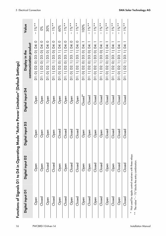
Func
tions
of Si
gnals
D1 t
o D4 i
n Ope
ratin
g Mod
e "Ac
tive P
ower
Limi
tatio
n" (D
efault
Settin
gs)
Digit
al inp
ut D1
Digit
al inp
ut D2
Digit
al inp
ut D3
Digit
al inp
ut D4
Disp
lay in
the
comm
unica
tion p
rodu
ctVa
lue
Open
Open
Open
Open
D1: 0
| D2:
0| D
3: 0|
D4:
0 −1
%**
**Th
e valu
e "−1
%" bl
ocks
the en
try co
mbina
tion.
Clos
edOp
enOp
enOp
enD1
: 1| D
2: 0|
D3:
0| D
4: 0
0%Op
enCl
osed
Open
Open
D1: 0
| D2:
1| D
3: 0|
D4:
030
%Cl
osed
Clos
edOp
enOp
enD1
: 1| D
2: 1|
D3:
0| D
4: 0
−1%*
*Op
enOp
enClo
sedOp
enD1
: 0| D
2: 0|
D3:
1| D
4: 0
60%
Clos
edOp
enClo
sedOp
enD1
: 1| D
2: 0|
D3:
1| D
4: 0
−1%*
*Op
enCl
osed
Clos
edOp
enD1
: 0| D
2: 1|
D3:
1| D
4: 0
−1%*
*Cl
osed
Clos
edCl
osed
Open
D1: 1
| D2:
1| D
3: 1|
D4:
0−1
%**
Open
Open
Open
Clos
ed*
*No
t use
d for
ripple
contr
ol rec
eivers
with
three
relay
s
D1: 0
| D2:
0| D
3: 0|
D4:
110
0%Cl
osed
Open
Open
Clos
edD1
: 1| D
2: 0|
D3:
0| D
4: 1
−1%*
*Op
enCl
osed
Open
Clos
edD1
: 0| D
2: 1|
D3:
0| D
4: 1
−1%*
*Cl
osed
Clos
edOp
enCl
osed
D1: 1
| D2:
1| D
3: 0|
D4:
1−1
%**
Open
Open
Clos
edCl
osed
D1: 0
| D2:
0| D
3: 1|
D4:
1−1
%**
Clos
edOp
enClo
sedCl
osed
D1: 1
| D2:
0| D
3: 1|
D4:
1−1
%**
Open
Clos
edCl
osed
Clos
edD1
: 0| D
2: 1|
D3:
1| D
4: 1
−1%*
*Cl
osed
Clos
edClo
sedCl
osed
D1: 1
| D2:
1| D
3: 1|
D4:
1−1
%**

SMA Solar Technology AG 5 Electrical Connection
Installation Manual PWCBRD-10-IA-en-14 17
Procedure:
2. Dismantle the connection cable by 4 cm.3. Trim unused insulated wires flush with the cable sheath.4. Strip the wire insulation by 6 mm.5. Connect the connection cable to the ripple control receiver (see ripple control receiver manual)
and write down the wire colours.
6. If you want to insert two cables through the cable gland M25 of the inverter, remove the cable support sleeve of the cable gland. If necessary, loosen the swivel nut of the cable gland.
7. Lead the connection cable through the cable support sleeve with two holes and the cable gland. Push the cable support sleeve with two holes into the cable gland.
Damage to the module due to high voltage• Only connect a ripple control receiver with a relay that is exclusively supplied by the 12 V
output of the module.
Operating the SMA Power Control Module and the multifunction relay in the inverter in parallel
• If you want to operate the SMA Power Control Module and the multifunction relay in parallel, make sure that no more than 30 V DC or 25 V AC are connected to the multifunction relay.
1.Danger to life due to electric shock from faulty connection of the ripple control receiverIn the event of faulty connection of the connection cable to the ripple control receiver, mains voltage may be present in the module.
• Do not connect insulated wires of the connection cable to the phase conductors of the ripple control receiver.
• When connecting, ensure that no bridge is being used in the ripple control receiver.
Signal Insulated wire colourD1D2D3D4+12 V

5 Electrical Connection SMA Solar Technology AG
18 PWCBRD-10-IA-en-14 Installation Manual
8. Remove the protective cover of the multifunction relay and insert the cable through the opening of the protective cover.
10. Plug the five-pole plug into the DIGITAL socket on the module.
11. Connect the connection cable to the five-pole plug. Plug the conductor into the conductor entry. Make sure that the noted wire colours correspond.
12. Tighten the swivel nut hand-tight on the cable gland.13. Recommission the inverter (see inverter installation manual).
9.Danger to life due to live cablesIf an insulated wire, e.g. L1, L2 or L3 comes loose from the AC terminal, and touches the connection cable of the ripple control receiver for example, the connection cable is live.
• Attach the protective cover of the multifunction relay. This isolates the AC connection area in the inverter from other terminals.

SMA Solar Technology AG 5 Electrical Connection
Installation Manual PWCBRD-10-IA-en-14 19
5.4 Information on Module ConfigurationActive power reduction to one of the 16 values set is realised within five seconds in the inverter. Grid disconnection is possible within two seconds. In order to block an entry combination, the value " − 1%" must be set in the communication product (see table on page 16). This allows that unassigned entry combinations can be blocked.If the network operator does not allow that the inverter still feeds in a low amount of active power when limited to 0%, you must set the following parameter for grid disconnection. Setting this parameter additionally opens the grid relays at a command of 0%. The inverter disconnects from the electricity grid and grid feed-in is interrupted. Depending on the type of communication and the communication product used, the parameter name may vary:
When the parameter is activated (Yes), the inverter disconnects from the electricity grid when the signal "0%" is issued. When the parameter is deactivated (No), the inverter continues to feed in with minimum power when the signal "0%" is issued.
Type of communication
Parameter name Setting
BLUETOOTH Equipment & device control system >Configuration of the feed-in management >Grid disconn. at 0% specif. by feeding management
YesNo
RS485 P-GriSwOpnZerW YesNo

6 Troubleshooting SMA Solar Technology AG
20 PWCBRD-10-IA-en-14 Installation Manual
6 TroubleshootingProblem Cause and corrective measuresThe inverter with module is not displayed in Sunny Explorer.
The inverter with module has not been commissioned.Corrective measure:
• Commission the inverter with module (see the inverter installation manual).
The module is not properly installed.Corrective measure:
• Ensure that the module is installed correctly and that the connections have been made correctly.
The firmware version of the inverter is not supported (see Section 2.3 "Supported Products", page 9).Corrective measure:
• Update the firmware of the inverter (see the inverter installation manual).
The software version of Sunny Explorer is older than version 1.06.Corrective measure:
• Make sure that Sunny Explorer from software version 1.06 is installed on the computer.
SMA Solar Technology AG 7 Decommissioning
Installation Manual PWCBRD-10-IA-en-14 21
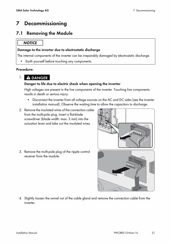
7 Decommissioning7.1 Removing the Module
Procedure:
2. Remove the insulated wires of the connection cable from the multi-pole plug. Insert a flat-blade screwdriver (blade width: max. 3 mm) into the actuation lever and take out the insulated wires.
3. Remove the multi-pole plug of the ripple control receiver from the module.
4. Slightly loosen the swivel nut of the cable gland and remove the connection cable from the inverter.
Damage to the inverter due to electrostatic dischargeThe internal components of the inverter can be irreparably damaged by electrostatic discharge.
• Earth yourself before touching any components.
1.Danger to life due to electric shock when opening the inverterHigh voltages are present in the live components of the inverter. Touching live components results in death or serious injury.
• Disconnect the inverter from all voltage sources on the AC and DC sides (see the inverter installation manual). Observe the waiting time to allow the capacitors to discharge.

7 Decommissioning SMA Solar Technology AG
22 PWCBRD-10-IA-en-14 Installation Manual
5. Loosen the screw M4x10 fastening the module to the inverter using a Torx screwdriver (T 20).
6. Remove the module from the inverter. The spacers remain in the inverter.
7. Close the inverter and recommission it (see the inverter installation manual).
7.2 Packing the Module for Shipment• Pack the module for shipment. Use the original packaging or packaging that is suitable for the
weight and size of the module (see Section 8 "Technical Data", page 23).
7.3 Disposing of the Module• Dispose of the module in accordance with the disposal regulations for electronic waste
applicable at the installation site.
SMA Solar Technology AG 8 Technical Data
Installation Manual PWCBRD-10-IA-en-14 23
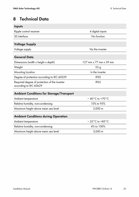
8 Technical DataInputsRipple control receiver 4 digital inputsS0 interface No function
Voltage SupplyVoltage supply Via the inverter
General DataDimensions (width x height x depth) 127 mm x 77 mm x 39 mmWeight 55 gMounting location In the inverterDegree of protection according to IEC 60529 IP20Required degree of protection of the inverter according to IEC 60629
IP65
Ambient Conditions for Storage/TransportAmbient temperature − 40°C to +70°CRelative humidity, non-condensing 10% to 95%Maximum height above mean sea level 3,000 m
Ambient Conditions during OperationAmbient temperature − 25°C to +85°CRelative humidity, non-condensing 4% to 100%Maximum height above mean sea level 3,000 m

9 Contact SMA Solar Technology AG
24 PWCBRD-10-IA-en-14 Installation Manual
9 ContactIf you have technical problems concerning our products, please contact the SMA Service Line. We require the following data in order to provide you with the necessary assistance:
• Inverter:– Serial number– Firmware version– Special country-specific settings (if applicable)
• Module:– Serial number– Hardware version
• Communication product (e.g. Sunny Explorer)– Type– Serial number or software version
• Detailed description of the problemAustralia SMA Australia Pty Ltd.
SydneyToll free for Australia:
1800 SMA AUS (1800 762 287)
International: +61 2 9491 4200Belgien/Belgique/België
SMA Benelux BVBA/SPRLMechelen
+32 15 286 730
Brasil Vide España (Espanha)Česko SMA Central & Eastern Europe
s.r.o.Praha
+420 235 010 417
Chile Ver EspañaDanmark Se Deutschland (Tyskland)Deutschland SMA Solar Technology AG
NiestetalMedium Power SolutionsWechselrichter: Kommunikation:
+49 561 9522-1499 +49 561 9522-2499
SMA Online Service Center: www.SMA.de/ServiceHybrid Energy SolutionsSunny Island: +49 561 9522-399PV-Diesel Hybridsysteme:
+49 561 9522-3199
Power Plant SolutionsSunny Central: +49 561 9522-299
SMA Solar Technology AG 9 Contact
Installation Manual PWCBRD-10-IA-en-14 25
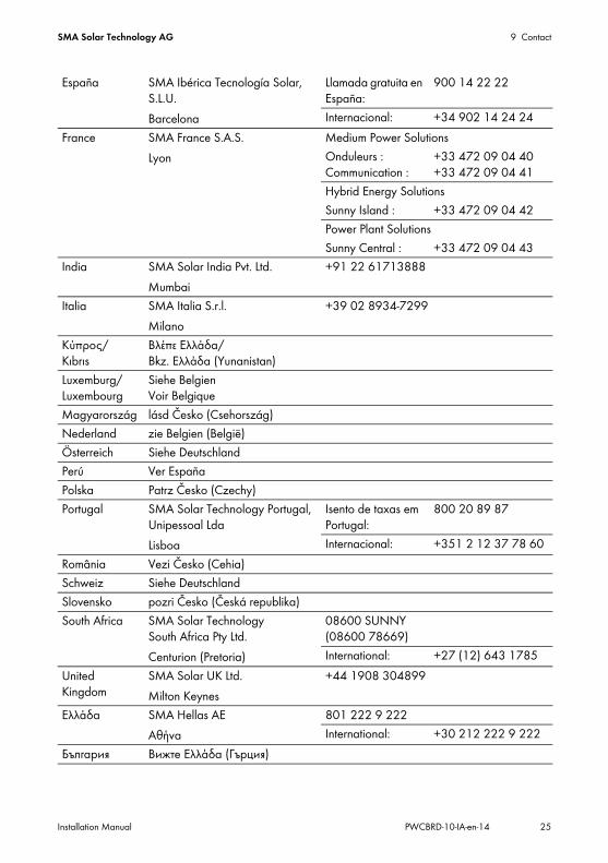
España SMA Ibérica Tecnología Solar, S.L.U.Barcelona
Llamada gratuita en España:
900 14 22 22
Internacional: +34 902 14 24 24France SMA France S.A.S.
LyonMedium Power SolutionsOnduleurs : Communication :
+33 472 09 04 40 +33 472 09 04 41
Hybrid Energy SolutionsSunny Island : +33 472 09 04 42Power Plant SolutionsSunny Central : +33 472 09 04 43
India SMA Solar India Pvt. Ltd.Mumbai
+91 22 61713888
Italia SMA Italia S.r.l.Milano
+39 02 8934-7299
Κύπρος/ Kıbrıs
Βλέπε Ελλάδα/ Bkz. Ελλάδα (Yunanistan)
Luxemburg/Luxembourg
Siehe Belgien Voir Belgique
Magyarország lásd Česko (Csehország)Nederland zie Belgien (België)Österreich Siehe DeutschlandPerú Ver EspañaPolska Patrz Česko (Czechy)Portugal SMA Solar Technology Portugal,
Unipessoal LdaLisboa
Isento de taxas em Portugal:
800 20 89 87
Internacional: +351 2 12 37 78 60România Vezi Česko (Cehia)Schweiz Siehe DeutschlandSlovensko pozri Česko (Česká republika)South Africa SMA Solar Technology
South Africa Pty Ltd.Centurion (Pretoria)
08600 SUNNY (08600 78669)International: +27 (12) 643 1785
United Kingdom
SMA Solar UK Ltd.Milton Keynes
+44 1908 304899
Ελλάδα SMA Hellas AEΑθήνα
801 222 9 222International: +30 212 222 9 222
България Вижте Ελλάδα (Гърция)
9 Contact SMA Solar Technology AG
26 PWCBRD-10-IA-en-14 Installation Manual
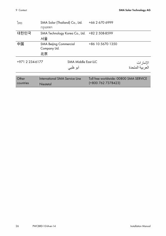
SMA Solar (Thailand) Co., Ltd. +66 2 670 6999
대한민국 SMA Technology Korea Co., Ltd.서울
+82 2 508-8599
中国 SMA Beijing Commercial Company Ltd.北京
+86 10 5670 1350
+971 2 234-6177 SMA Middle East LLC
Other countries
International SMA Service LineNiestetal
Toll free worldwide: 00800 SMA SERVICE (+800 762 7378423)
��������������
����� �����! �


www.SMA-Solar.comSMA Solar Technology


