91
Installation Manual TriPac e ™ Auxiliary Heating and Cooling Temperature Management System TK 54468-19-IM (Rev. 2, 12/11)

Installation Manual
Providing equipment and services to manage controlled-temperature environments for food and other temperature-sensitive products, our Climate Control Technologies sector encompasses both transport and stationary refrigeration solutions. Our product brands include Thermo King®, a world leader in transport temperature control systems, and Hussmann®, a manufacturer of refrigeration and food merchandising equipment.
www.thermoking.com www.hussmann.com www.ingersollrand.com
©2008 Ingersoll-Rand Company Printed in U.S.A. on Recycled Paper
TriPace ™ Auxiliary Heating and Cooling Temperature
Management SystemTK 54468-19-IM (Rev. 2, 12/11)

Installation Manual
TriPace ™
Auxiliary Heating and CoolingTemperature Management SystemTK-54468-19-IM (Rev. 2, 12/11)
Copyright© 2010 Thermo King Corp., Minneapolis, MN, U.S.A.
Printed in U.S.A.

2
Installation Manual
Release History
Released 04/10 Released manual
Rev. 1 (06/10) Corrected pages 62-63, the positive and negative studs were shown reversed on the Compressor Controller Board.
Rev. 2 (12/11) Updated the Safety section by including Battery Installation and Cable Routing warnings on page7.

3
Introduction
This manual was written to assist with the installation of the Thermo King TriPace Auxiliary Heating and Cooling System onto a typical semi tractor with
sleeper. While it is not intended to be specific to a particular vehicle, the information in this manual will provide the installer with details to correctly and
safely install each of the APU components.
Before beginning the installation, the installer should confirm with the customer the location for each of the APU’s components by using the
APU Installation Questionnaire. The customer should also be made aware that modifications to existing equipment may be necessary to complete the
installation.
Modifications may include:
• OEM components on the chassis may need to be relocated to
accommodate the installation of the APU battery box.
• OEM fuel tank may need to be changed to a smaller size to
accommodate the installation of the APU battery box.
• APU condenser may be directly mounted to the outside of the sleeper.
• APU evaporator, power inverter and/or converter may be installed in
existing storage spaces under the bunk or in the tool box areas.
• APU heating and A/C duct work may to be routed with vents installed
in existing closets or storage compartments.
• Tractor’s engine must be fitted with an upgraded alternator and wiring
of 185 amps or more.
• For base level performance - tractor battery box must have four 12 Vdc
batteries connected to provide 12 Vdc output.
• For optimum level performance - tractor batteries may be upgraded to
Thermo King NXT 1150 CCA absorbed glass mat (AGM) batteries.
Due to its complexity, you should not attempt this installation unless
you:
• are an experienced mechanic.
• can safely lift 75 lbs. (34 kilos).
• are EPA Section 609 certified and trained in the repair and maintenance
of mobile air conditioning systems.
• have a basic understanding of electricity and electrical wiring.
• have the necessary tools and equipment to complete the installation.
This manual is published for informational purposes only. Thermo King makes no representations warranties express or implied, with respect to
the information recommendations and descriptions contained herein. Information provided should not be regarded as all-inclusive or covering
all contingencies. If further information is required, Thermo King Corporation Service Department should be consulted.
Thermo King’s warranty shall not apply to any equipment which has been “so installed, maintained, repaired or altered as, in the manufacturer’s
judgment, to affect its integrity.”
Manufacturer shall have no liability to any person or entity for any personal injury, property damage or any other direct, indirect,
special, or consequential damages whatsoever, arising out of the use of this manual or any information, recommendations or
descriptions contained herein.

4
Table Of Contents
Safety Precautions . . . . . . . . . . . . . . . . . . . . . . . . . . . . . . . . . . . . . . . . . . . . . . 5
Tips for a Successful Installation . . . . . . . . . . . . . . . . . . . . . . . . . . . . . . . . . . 9
Battery Box Dimensions . . . . . . . . . . . . . . . . . . . . . . . . . . . . . . . . . . . . . . . . . 12
Evaporator/Control Box Dimensions . . . . . . . . . . . . . . . . . . . . . . . . . . . . . . . 13
Condenser with Receiver Drier Dimensions . . . . . . . . . . . . . . . . . . . . . . . . . 14
HMI Dimensions . . . . . . . . . . . . . . . . . . . . . . . . . . . . . . . . . . . . . . . . . . . . . . . . 15
1000 Watt Power Inverter Dimensions (Option) . . . . . . . . . . . . . . . . . . . . . . 16
AC/DC Power Converter Dimensions (Option) . . . . . . . . . . . . . . . . . . . . . . . 17
Required Tools and Additional Supplies . . . . . . . . . . . . . . . . . . . . . . . . . . . 18
Typical Component Locations . . . . . . . . . . . . . . . . . . . . . . . . . . . . . . . . . . . . 19
Tractor and APU Battery Recommendations . . . . . . . . . . . . . . . . . . . . . . . . 20
Battery Box Installation . . . . . . . . . . . . . . . . . . . . . . . . . . . . . . . . . . . . . . . . . 22
Condenser and Receiver Drier Installation . . . . . . . . . . . . . . . . . . . . . . . . . . 26
Evaporator/Control Box Installation . . . . . . . . . . . . . . . . . . . . . . . . . . . . . . . 28
Fabricating Refrigeration Hoses . . . . . . . . . . . . . . . . . . . . . . . . . . . . . . . . . . 34
A/C Hose Installation . . . . . . . . . . . . . . . . . . . . . . . . . . . . . . . . . . . . . . . . . . . . 40
A/C System Evacuation and Leak Check Procedures . . . . . . . . . . . . . . . . . 42
D2 Heater Installation . . . . . . . . . . . . . . . . . . . . . . . . . . . . . . . . . . . . . . . . . . . 44
D2 Heater Duct Installation . . . . . . . . . . . . . . . . . . . . . . . . . . . . . . . . . . . . . . 50
D4 High Output Heater Installation (Option) . . . . . . . . . . . . . . . . . . . . . . . . 52
D4 High Output Heater Duct Installation (Option) . . . . . . . . . . . . . . . . . . . . 58
A/C Duct Installation . . . . . . . . . . . . . . . . . . . . . . . . . . . . . . . . . . . . . . . . . . . . 60
Main Harness Installation . . . . . . . . . . . . . . . . . . . . . . . . . . . . . . . . . . . . . . . . 62
Condenser Fan and Sensor Harness Installation . . . . . . . . . . . . . . . . . . . . 64
Ignition Switch and Harness Installation . . . . . . . . . . . . . . . . . . . . . . . . . . . 66
HMI Installation . . . . . . . . . . . . . . . . . . . . . . . . . . . . . . . . . . . . . . . . . . . . . . . . 68
Heater Harness Installation . . . . . . . . . . . . . . . . . . . . . . . . . . . . . . . . . . . . . . 70
Auxiliary AC Power Accessories (Optional) . . . . . . . . . . . . . . . . . . . . . . . . . 72
Fuel Pickup Tube Installation . . . . . . . . . . . . . . . . . . . . . . . . . . . . . . . . . . . . 74
Heater Fuel Pump and Fuel Line Installation . . . . . . . . . . . . . . . . . . . . . . . . 78
Heater Fuel Pump Connections . . . . . . . . . . . . . . . . . . . . . . . . . . . . . . . . . . . 80
Installing the Battery Cables . . . . . . . . . . . . . . . . . . . . . . . . . . . . . . . . . . . . . 82
Priming the Heater Fuel Pump . . . . . . . . . . . . . . . . . . . . . . . . . . . . . . . . . . . . 84
A/C System Charging Procedures . . . . . . . . . . . . . . . . . . . . . . . . . . . . . . . . 86
System Check List . . . . . . . . . . . . . . . . . . . . . . . . . . . . . . . . . . . . . . . . . . . . . 89

5
Safety Precautions
Caution
SEVERE COMPRESSOR DAMAGE will result from operating the A/C system before completing the
installation which includes: installing the condenser, receiver drier, evaporator, connecting the
refrigeration lines, leak testing, evacuation, clean-up, and charging the system with the correct type and
amount of refrigerant.
Recover Refrigerant
At Thermo King, we recognize the need to preserve the environment and limit the potential harm to the
ozone layer that can result from allowing refrigerant to escape into the atmosphere.
We strictly adhere to a policy that promotes the recovery and limits the loss of refrigerant into the
atmosphere.

6
Safety Precautions (continued)
The symbol appears next to a point that is particularly important:
DANGER: Addresses a circumstance that, if encountered, will
lead to death or serious injury
WARNING: Addresses a circumstance that, if encountered,
might lead to death or serious injury.
CAUTION: Addresses a circumstance that, if encountered,
may cause damage to equipment or minor injury.
DANGER: Never apply heat to a sealed refrigeration system
or container because it could explode, causing death or
serious injury
DANGER: Fluorocarbon refrigerants, in the presence of an
open flame or electrical short, produce toxic gases that are
severe respiratory irritants capable of causing death.
DANGER: Be careful when working with a refrigerant or
refrigeration system in any enclosed or confined area with a
limited air supply (i.e., a trailer, container or the hold of a
ship). Refrigerant tends to displace air and can cause oxygen
depletion which may result in death by suffocation.
WARNING: Always wear goggles or safety glasses.
Refrigerant liquid, refrigeration oil, and battery acid can
permanently damage the eyes (see First Aid under
Refrigeration Oil).
WARNING: Keep your hands away from fans when the unit is
running.
WARNING: When using ladders to install or service
refrigeration systems, always observe the ladder
manufacturer’s safety labels and warnings. A work platform is
the recommended method for installations.
WARNING: Never drill holes into the unit. Holes drilled into
the unit may weaken structural components. Holes drilled into
electrical wiring can cause fire or explosion.
WARNING: Make sure all mounting bolts are tight and are of
correct length for their particular application
WARNING: Installer supplied lifting eyebolts must be forged
steel, 1/2” (12 mm) diameter.
WARNING: Use only locking lifting hooks to attach to the lifting
eyebolts.
7
Safety Precautions (continued)
Battery Installation and Cable Routing Refrigerant
First Aid
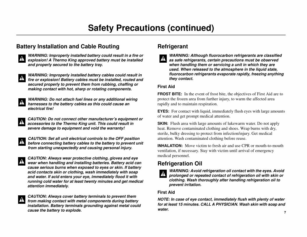
FROST BITE: In the event of frost bite, the objectives of First Aid are to
protect the frozen area from further injury, to warm the affected area
rapidly and to maintain respiration.
EYES: For contact with liquid, immediately flush eyes with large amounts
of water and get prompt medical attention.
SKIN: Flush area with large amounts of lukewarm water. Do not apply
heat. Remove contaminated clothing and shoes. Wrap burns with dry,
sterile, bulky dressing to protect from infection/injury. Get medical
attention. Wash contaminated clothing before reuse.
INHALATION: Move victim to fresh air and use CPR or mouth-to-mouth
ventilation, if necessary. Stay with victim until arrival of emergency
medical personnel.
Refrigeration Oil
First Aid
NOTE: In case of eye contact, immediately flush with plenty of water
for at least 15 minutes. CALL A PHYSICIAN. Wash skin with soap and
water.
WARNING: Improperly installed battery could result in a fire or explosion! A Thermo King approved battery must be installed and properly secured to the battery tray.
WARNING: Improperly installed battery cables could result in fire or explosion! Battery cables must be installed, routed and secured properly to prevent them from rubbing, chaffing or making contact with hot, sharp or rotating components.
WARNING: Do not attach fuel lines or any additional wiring harnesses to the battery cables as this could cause an electrical fire!
CAUTION: Do not connect other manufacturer’s equipment or accessories to the Thermo King unit. This could result in severe damage to equipment and void the warranty!
CAUTION: Set all unit electrical controls to the OFF position before connecting battery cables to the battery to prevent unit from starting unexpectedly and causing personal injury.
CAUTION: Always wear protective clothing, gloves and eye wear when handling and installing batteries. Battery acid can cause serious burns when exposed to eyes or skin. If battery acid contacts skin or clothing, wash immediately with soap and water. If acid enters your eye, immediately flood it with running cold water for at least twenty minutes and get medical attention immediately.
CAUTION: Always cover battery terminals to prevent them from making contact with metal components during battery installation. Battery terminals grounding against metal could cause the battery to explode.
WARNING: Although fluorocarbon refrigerants are classified as safe refrigerants, certain precautions must be observed when handling them or servicing a unit in which they are used. When released to the atmosphere in the liquid state, fluorocarbon refrigerants evaporate rapidly, freezing anything they contact.
WARNING: Avoid refrigeration oil contact with the eyes. Avoid prolonged or repeated contact of refrigeration oil with skin or clothing. Wash thoroughly after handling refrigeration oil to prevent irritation.

8
Heater Safety Precautions
IMPORTANT: Correct installation of this heater is necessary to ensure safe and proper operation. BEFORE installing the heater, thoroughly read and
understand this manual and the heater manufacturer’s manuals included with the heater.
DANGER: EXPLOSION HAZARD or FIRE HAZZARD! Failure
to follow these instruction could cause a explosion or fire
resulting in serious or fatal injury!
• Heater must be turned off while re-fueling.
• Install heater so it will maintain a minimum distance of 2” from
any flammable or heat sensitive material.
• Install the exhaust system so it will maintain a minimum
distance of 2” from any flammable or heat sensitive material.
• Stored items in may shift while vehicle is in operation and
should be secured adequately to prevent contact with the heater.
• Use a protective air intake grille on the air inlet side of the
heater to prevent objects from being sucked in.
• The heater must only be operated when the maintenance flap is
closed and the outlet hood is mounted in position.
• Do not install heater in enclosed areas where combustible fumes
may be present.
• Do not store or transport combustibles (road flares, starting
fluids, fuel containers, oil cans, spray cans, gas cartridges, fire
extinguishers, cleaning rags, clothing, paper, etc.) in the same
compartment as the heater.
• Ensure that the fuel system is intact and there are no leaks.
• Do not route electrical wires, harness or battery cables together
with fuel lines.
DANGER: ASPHYXIATION HAZARD! Failure to follow these
instructions could cause oxygen depletion resulting in serious or
fatal injury!
• Route the heater exhaust so that exhaust fumes can not enter
into the passenger compartments.
• Ensure an air tight seal will be maintained between the heater
and mounting surface and at any exhaust connection points.
• Ensure that heating air supply is taken from an area where
poisonous gases will not be present.
• When the heater is installed in a enclosed compartment separate
from the evaporator, a inlet for return air must be installed to
provide the heater with a fresh air supply.
• If running exhaust components through an enclosed
compartment, ensure that it is vented to the outside.
• The enclosed compartment must be free of any holes, cracks or
rusted out areas to prevent fumes from entering into the
passenger compartment.
• The heater must be installed flush with the floor pan (i.e. sheet
metal, fiberglass, etc.) to ensure proper sealing of the mounting
plate and gasket.
• The heater must not be operated in closed areas such as garages,
buildings, warehouses, etc.
• Do not inhale exhaust fumes.
9
Tips for a Successful Installation
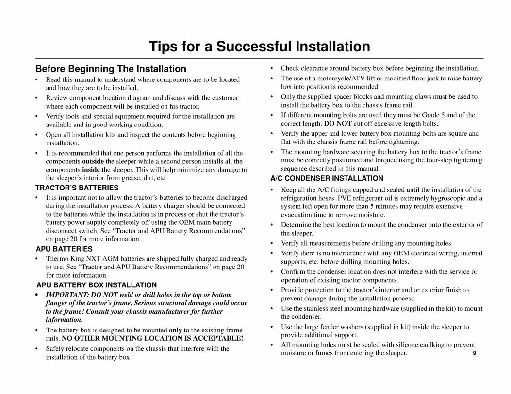
Before Beginning The Installation• Read this manual to understand where components are to be located
and how they are to be installed.
• Review component location diagram and discuss with the customer
where each component will be installed on his tractor.
• Verify tools and special equipment required for the installation are
available and in good working condition.
• Open all installation kits and inspect the contents before beginning
installation.
• It is recommended that one person performs the installation of all the
components outside the sleeper while a second person installs all the
components inside the sleeper. This will help minimize any damage to
the sleeper’s interior from grease, dirt, etc.
TRACTOR’S BATTERIES
• It is important not to allow the tractor’s batteries to become discharged
during the installation process. A battery charger should be connected
to the batteries while the installation is in process or shut the tractor’s
battery power supply completely off using the OEM main battery
disconnect switch. See “Tractor and APU Battery Recommendations”
on page 20 for more information.
APU BATTERIES
• Thermo King NXT AGM batteries are shipped fully charged and ready
to use. See “Tractor and APU Battery Recommendations” on page 20
for more information.
APU BATTERY BOX INSTALLATION
• IMPORTANT: DO NOT weld or drill holes in the top or bottom
flanges of the tractor’s frame. Serious structural damage could occur
to the frame! Consult your chassis manufacturer for further
information.
• The battery box is designed to be mounted only to the existing frame
rails. NO OTHER MOUNTING LOCATION IS ACCEPTABLE!
• Safely relocate components on the chassis that interfere with the
installation of the battery box.
• Check clearance around battery box before beginning the installation.
• The use of a motorcycle/ATV lift or modified floor jack to raise battery
box into position is recommended.
• Only the supplied spacer blocks and mounting claws must be used to
install the battery box to the chassis frame rail.
• If different mounting bolts are used they must be Grade 5 and of the
correct length. DO NOT cut off excessive length bolts.
• Verify the upper and lower battery box mounting bolts are square and
flat with the chassis frame rail before tightening.
• The mounting hardware securing the battery box to the tractor’s frame
must be correctly positioned and torqued using the four-step tightening
sequence described in this manual.
A/C CONDENSER INSTALLATION
• Keep all the A/C fittings capped and sealed until the installation of the
refrigeration hoses. PVE refrigerant oil is extremely hygroscopic and a
system left open for more than 5 minutes may require extensive
evacuation time to remove moisture.
• Determine the best location to mount the condenser onto the exterior of
the sleeper.
• Verify all measurements before drilling any mounting holes.
• Verify there is no interference with any OEM electrical wiring, internal
supports, etc. before drilling mounting holes.
• Confirm the condenser location does not interfere with the service or
operation of existing tractor components.
• Provide protection to the tractor’s interior and or exterior finish to
prevent damage during the installation process.
• Use the stainless steel mounting hardware (supplied in the kit) to mount
the condenser.
• Use the large fender washers (supplied in kit) inside the sleeper to
provide additional support.
• All mounting holes must be sealed with silicone caulking to prevent
moisture or fumes from entering the sleeper.

10
Tips for a Successful Installation (continued)
A/C EVAPORATOR/CONTROL BOX INSTALLATION
• Keep all the A/C fittings capped and sealed until the installation of the
refrigeration hoses. PVE refrigerant oil is extremely hygroscopic and a
system left open for more than 5 minutes may require extensive
evacuation time to remove moisture.
• Determine the best location for the A/C evaporator/control box inside
the sleeper, typically under the bunk and flush to the front bulkhead.
• Allow adequate clearance for attaching the two air outlet tubes.
• Verify there is no interference with any OEM electrical wiring, internal
floor supports, etc. before drilling any mounting holes in the tractor.
• The evaporator/control box should be mounted directly onto the floor
mat inside the sleeper. Use the supplied template to properly locate the
drain and mounting holes.
• Always install the drain valves (kazoos) into drain holes located on the
bottom pan of the evaporator.
• The A/C vents should be located and installed to provide maximum air
circulation in the sleeper such as: LOW (floor level), MEDIUM (above
lower bunk level) or HIGH (above upper bunk level).
• All mounting holes must be sealed with silicone caulk to prevent
moisture or exhaust fumes from entering the sleeper.
• All edges of access holes made in fiberglass and wood composite floors
must be sealed correctly with fiberglass cloth and resin.
HEATER INSTALLATION
• Determine the best location of the heater inside the sleeper, typically
under the bunk. Allow clearance for dismantling for service.
• Install heater so it will maintain a minimum distance of 2.00 inches
(50.8 mm) from any heat sensitive or flammable material.
• The heater must only be mounted on a flat horizontal surface.
• Heater must be installed flush with the floor pan (i.e. sheet metal,
fiberglass, etc.) to ensure proper sealing of the mounting plate and
gasket.
• All edges of access holes made in fiberglass and wood composite floors
must be sealed correctly with fiberglass cloth and resin.
• Outside air intake and exhaust hoses must be installed correctly for the
heater to operate safely.
• Exhaust hose should be mounted slightly downwards to help drain off
condensation.
• Install exhaust hose so it will maintain a minimum distance of 2.00
inches (50.8 mm) from any heat sensitive or flammable material.
• Inside air inlet and outlet ducts must be installed correctly for the heater
to operate safely:
• Pulse fuel pump must be installed at a 15 to 35 degree angle from
horizontal to operate correctly.
• Fuel pickup tube must be installed correctly in the fuel tank or the
heater will not operate.
• Fuel line from the pickup tube to the fuel pump to the heater should be
routed at a continuous rise.
• Use a hose cutter or sharp knife to cut plastic fuel lines. Do not use a
wire cutter as this will pinch the plastic fuel line closed.
• Do not route electrical wires, harness or battery cables together with
fuel lines.
• BEFORE operating the heater, the fuel lines must be bled of air using
the Heater Priming Harness (204-1144) or damage to the fuel pump
will result. See “Priming the Heater Fuel Pump” on page 84.
• The Diagnostic Code Reader (204-1143) must be used to setup and
operate the heater in the run-in mode. See “Operation Checkout
Procedures” on page 90.

11
Tips for a Successful Installation (continued)
A/C HOSE CONNECTIONS AND ROUTING
• Keep all the A/C fittings capped and sealed until the installation of the
refrigeration hoses. PVE refrigerant oil is extremely hygroscopic and a
system left open for more than 5 minutes may require extensive
evacuation time to remove moisture.
• Only cut refrigerant hoses with the correct hose cutting tool (204-677).
NEVER USE A SAW!
• Always use the correct hose fitting tool (204-1045) when assembling
refrigeration hoses.
• Always lubricate hose fittings with POE refrigerant oil when
assembling to refrigeration hoses.
• Always install and lubricate O-rings with POE refrigerant oil when
connecting refrigeration hose fittings to component connection fittings.
• Refrigeration hoses should be installed onto components in such a way
as to allow for vibration and movement of the cab. THEY SHOULD
NEVER BE STRETCHED TIGHT!
• All refrigeration connections should be tightened securely using two
wrenches.
• Always keep refrigeration hoses from rubbing or chafing against sharp
metal objects, rotating components or hot components.
• Protective covers or sleeving (installer supplied) for the refrigeration
hoses may be required depending on the installation.
• Always install the condenser’s receiver drier in the direction indicated
by the arrow.
• Thermo King Evacuation Station (204-725) and Evacuation Station
Operation and Field Application Instructions (TK-40612) are
recommended.
• The oil in the evacuation station vacuum pump should be changed after
each use.
• The A/C system must be leak free. Check for leaks by using an
electronic leak detector.
• The A/C system will be charged with 2.0 bs. of R134a refrigerant.
ELECTRICAL WIRING AND HMI CONTROLLER INSTALLATION
• Electrical wiring should be installed and routed in such a way as to
allow for vibration and movement of the cab.
THEY SHOULD NEVER BE STRETCHED TIGHT!
• Always keep electrical wiring from rubbing or chafing against sharp
metal objects, rotating components or hot objects.
• All electrical wiring should be neatly routed and secured with band
wraps or clamps.
• Do note route or bundle 110 Vac wires together with 12 Vdc wires.
• Do not route electrical wires, harness or battery cables together with
fuel lines.
• Excess length of battery cables should be cut off to reduce voltage
drop.
• Superlube (203-524) or equivalent should be applied to all electrical
connections.
• All main power and ground accessory connections must be installed
directly on top of the tractor’s battery terminal posts and tightened
securely. DO NOT INSTALL UNDER OEM BATTERY CABLES!

12
Battery Box Dimensions
NOTE: Dimensions shown in inches.
Approximate Weight 425 lbs. (193 kg)

13
Evaporator/Control Box Dimensions
NOTE: Dimensions shown in inches.
Approximate Weight 52 lbs. (23.5 kg)

14
Condenser with Receiver Drier Dimensions
NOTE: Dimensions shown in inches.
Approximate Weight 25 lbs. (11.3 kg)

15
HMI Dimensions
NOTE: Dimensions shown in inches.

16
1000 Watt Power Inverter Dimensions (Option)
NOTE: Dimensions shown in inches.
17
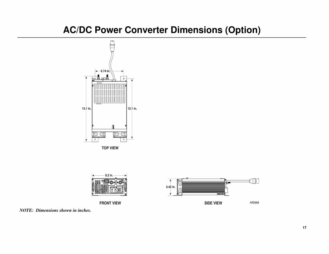
AC/DC Power Converter Dimensions (Option)
NOTE: Dimensions shown in inches.

18
Required Tools and Additional Supplies
Tools1. Typical Mechanics Tools
2. Floor Jack or Motorcycle/ATV Lift
3. Drill Motor
4. Drill Bit Set
5. 7/8'' dia. or 1'' Step Reamer (for evaporator drain and controller holes)
6. Hole Saws
• 1'' dia. (for fuel tank pickup tube)
• 2-1/2'' dia. (for heater inlet/outlet louver)
• 3'' dia. (access hole for evaporator hoses and electrical wiring)
• 4-1/4'' dia. (mounting A/C louvers, routing A/C ducts through bulkheads
and heater mounting hole)
7. Reciprocating Saw (return air opening)
8. 1/2'' Wrench
9. Level
10. Tape Measure
11. Utility Knife
12. Caulk Gun
13. Digital Meter (204-615)
14. Refrigerant Leak Detector (204-756)
15. Hose Fitting Tool (204-1045)
16. Hose Cutting Tool (204-677)
17. Heater Priming Harness (204-1144)
18. Shop Vacuum
19. R-134a Gauge Manifold with automotive connectors
20. Vacuum Pump (204-713)
21. Micron Gauge (204-720)
22. Heavy Duty Battery Charger
23. AMP pin removal tool (204-737)
24. AMP pin removal tool (204-1120)
25. Laptop Computer (IBM Compatible) with Microsoft Internet Explorer 6.0 or
higher installed.
26. USB Adapter Cable (204-1926)
Supplies (as required)1. RTV Silicone
2. Sealing Putty (203-391)
3. POE Refrigerant Oil (for lubricating hose fittings and o-rings)
4. Refrigerant 134a
5. Return air wall louver when needed (approximately 10'' x 12'')
6. Mounting Clamps #24 and #32 (to secure cables and hoses)
7. Band wraps (assorted sizes and lengths)
8. Upholstery Cleaner (aprox. 2 cans)
9. Cardboard or blankets (to protect interior)
10. Fiberglass Repair Kit
(only used for fiberglass and wood composite floors)

19
Typical Component Locations
TYPICAL COMPONENT LOCATIONS
1. Battery Box
2. Condenser / Receiver Drier
3. HMI Controller
4. Cab Heater
5. Evaporator / Control Box
6. Power Inverter (OPTIONAL)
7. Power Converter (OPTIONAL)
NOTE: Component locations will vary
with sleeper design.
1
2
3
4
5
6
7

20
Tractor and APU Battery Recommendations
Tractor’s Batteries
The tractor’s batteries should not be allowed to become discharged during
the APU installation process. Always connect a battery charger to the
tractor’s batteries before beginning the installation.
An alternative method is to shut the tractor’s battery power completely off
using the OEM main battery disconnect switch.
For base level performance - tractor battery box must have four 12 Vdc
batteries connected to provide 12 Vdc output.
For optimum level performance - Thermo King recommends that the
tractor’s batteries also be upgraded to Thermo King NXT 1150 CCA
absorbed glass mat (AGM) batteries.
NXT AGM BatteriesCharge Maintenance
Thermo King NXT AGM batteries are shipped fully charged. Fully
charged NXT AGM batteries that are kept in stock should not require
charging for 2 years if kept below 77 F (25 C). NXT AGM batteries should
be charged when the open circuit voltage (OCV) falls below 12.50 volts.
To charge the NXT AGM battery, use the following guidelines:
1. Verify the output voltage of your battery charger is capable of
maintaining 14.1 to 14.7 charging voltage. The recommended charging
voltage range for the NXT AGM battery is 14.1 to 14.7 volts. Voltages
are to be measured at the battery terminals with the battery connected
to the charger.
IMPORTANT: Never exceed 15 volts when charging the NXT AGM
battery. Exceeding 15 volts will cause pressure relief valves to open and
out-gas hydrogen and oxygen from inside the battery. This will shorten
the life of the battery and could lead to premature battery failure.
2. Battery chargers with the battery type output setting should be set to
AGM type battery. Do not set the output type to gel cell or maintenance
free settings.
3. Determine if your battery charger is an automatic or manual charger.
Manual battery chargers must be closely monitored during the charge
period and for this reason an automatic battery charger is preferred over
a manual charger.
a. Automatic battery chargers either charge up to a preset voltage and
shut off, or charge to a present voltage and then switch to a trickle
charge mode. Either one of these battery chargers is acceptable:
however the automatic charger that shuts off may not fully charge
the battery.
b. Manual battery chargers will have manual controls for setting the
charge amperage rate. The charge amperage rate will remain the
same until the battery charger is manually shut off.
NOTE: When using a manual battery charger, set the charger to charge
at 10 or 20 amps and limit the charging time based on the batteries state
of charge (SOC). Use the chart below as a general guide to determine the
amount of time necessary to charge the battery. DO NOT overcharge the
battery.

21
Tractor and APU Battery Recommendations
Cleaning a Battery
Use a damp cloth to clean the top of the battery to eliminate conductive
paths created by dirt and dried or wet electrolyte, and to prevent corrosion.
Use a battery terminal-cleaning tool that has nonconductive (plastic or
rubber) cover to clean the battery terminals when corrosion is present.
Replace any battery cables (or cable terminals) that are frayed, corroded,
swelled, or damaged to the extent that they can not be cleaned.
Battery Hold Down Hardware
Batteries are subjected to extreme shock loads and vibration. It is very
important to make sure the battery is secured by the proper mounting
hardware. Failure to secure the battery correctly can result in premature
battery failure. Using a torque wrench, torque the hold down nuts in two
step increments:
• STEP 1 - Torque each hold down nut to 60 in-lbs. (6.8 N•m)
• STEP 2 - Torque each hold down nut to 120 to 144 in-lbs. (13.5 to
16.3 N•m)
Battery Cable Mounting
On threaded stud type batteries, use only stainless steel nuts to fasten the
cable to the battery. Torque the nut to 150 to 200 in-lbs. (17 to 22.5 N•m).
On SAE post type batteries, use only stainless steel battery clamp bolts.
Torque the nut to 60 in-lbs. (7 N•m).
Determining Maximum Charge Time Using a Manual Charger
Voltmeter Reading State of Charge Time @ 10 Amps Time @ 20 Amps
12.84 Volts 100% 0 Hours 0 Hours
12.50 Volts 75% 2 Hours 1 Hour
12.20 Volts 50% 4 Hours 2 Hours
11.88 Volts 25% 6 Hours 3 Hours
WARNING: Overcharging can damage the battery and possibly cause a fire or explosion. Follow the battery charger’s recommendations for
monitoring batteries while charging. Batteries should be monitored while charging for signs of internal problems. Signs of internal problems
include bulging cases, extreme gassing, pungent smell, and extreme heat.If you notice any of these signs turn the charger off and allow the battery
to stabilize before handling or testing.

22
Battery Box Installation
STANDARD INSTALLATION METHOD - MOUNTING CLAWS
NOTE: DO NOT OIL THE BOLT THREADS!
1. Remove the cover from the battery box to access and remove hardware
that secures box to the shipping crate.
2. It is recommended that a modified floor jack or motorcycle/ATV lift be
used to install the battery box. Protection such as cardboard, shop rags,
etc. should be used under the box to prevent damage during
installation.
• Install lifting eyebolts, washers and nuts securely into the two holes
at the top of the battery box.
• Using locking lifting hooks, raise the battery box and place onto the
lift then remove lifting eyebolts, washers and nuts.
3. Using a lift, carefully raise the battery box into position. Install the 3/4''
bolts and washers through the mounting claws and the rear of the
battery box.
4. Loosely install the retainers and locking nuts inside the battery box.
5. With battery box still supported by a lift:
• Push battery box up tight to tractor’s frame.
• Adjust height of box so top and bottom mounting claws and bolts
are positioned flat on frame.
• Review (Detail A) - Lightly tighten mounting hardware only
enough to remove excess play.
6. Using a torque wrench, torque mounting bolts in four step increments
starting with top bolts, then bottom bolts.
STEP 1 - Torque top then bottom mounting bolts to 25 ft-lb. (33.9 N•m).
IMPORTANT: STOP and verify all mounting claws and bolts remained
flat on frame (Detail A). If they are not, loosen bolts, adjust as necessary
and retighten again to 25 ft-lb. (33.9 N•m).
STEP 2- After first step is successfully completed, torque top then bottom
bolts to 50 ft-lb. (67.8 N•m).
STEP 3- Next, torque top and then bottom bolts to 100 ft-lb.(135.6 N•m).
STEP 4 - Finally, recheck all bolts to confirm they are at 100 ft-lb.
(135.6 N•m)
IMPORTANT: DO NOT OVER-TORQUE MOUNTING BOLTS!
7. Remove the support lift and visually inspect installation for the
following:
• Mounting claws and bolts are correctly installed. They should be
square and flat on the frame (Detail A).
• If any mounting claws and bolts are improperly installed on the
frame (i/e. they resemble Details B & C) - adjust as necessary.
• Damaged, deformed or cracked components during installation -
must be replace immediately.
WARNING: Installer supplied lifting eyebolts must be forged
steel, 1/2''(12mm) diameter.
WARNING: Use only locking lifting hooks to attach to the lifting
eyebolts.
WARNING: DO NOT connect any of the TriPace battery cables to
any batteries at this time.
Special Tools Required
Modified Floor Jack or Motorcycle/ATV Lift
1/2” Drive Torque Wrench
IMPORTANT: The following steps are critical and must be
followed to ensure the safe installation of the battery box to the
tractor’s frame.

23
Battery Box Installation
WARNING: DO NOT connect any of the TriPace battery cables to any batteries at this time.
STANDARD INSTALLATION METHOD - MOUNTING CLAWS
24
Battery Box Installation
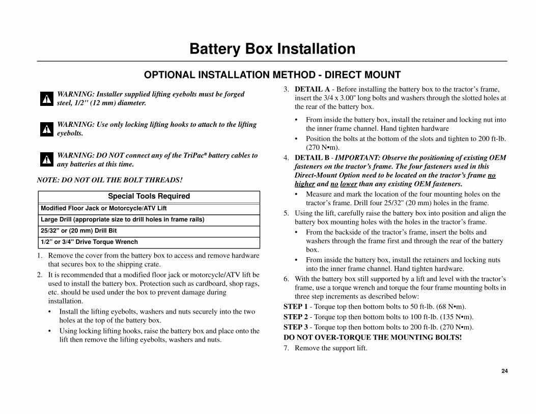
OPTIONAL INSTALLATION METHOD - DIRECT MOUNT
NOTE: DO NOT OIL THE BOLT THREADS!
1. Remove the cover from the battery box to access and remove hardware
that secures box to the shipping crate.
2. It is recommended that a modified floor jack or motorcycle/ATV lift be
used to install the battery box. Protection such as cardboard, shop rags,
etc. should be used under the box to prevent damage during
installation.
• Install the lifting eyebolts, washers and nuts securely into the two
holes at the top of the battery box.
• Using locking lifting hooks, raise the battery box and place onto the
lift then remove the lifting eyebolts, washers and nuts.
3. DETAIL A - Before installing the battery box to the tractor’s frame,
insert the 3/4 x 3.00'' long bolts and washers through the slotted holes at
the rear of the battery box.
• From inside the battery box, install the retainer and locking nut into
the inner frame channel. Hand tighten hardware
• Position the bolts at the bottom of the slots and tighten to 200 ft-lb.
(270 N•m).
4. DETAIL B - IMPORTANT: Observe the positioning of existing OEM
fasteners on the tractor’s frame. The four fasteners used in this
Direct-Mount Option need to be located on the tractor’s frame no
higher and no lower than any existing OEM fasteners.
• Measure and mark the location of the four mounting holes on the
tractor’s frame. Drill four 25/32'' (20 mm) holes in the frame.
5. Using the lift, carefully raise the battery box into position and align the
battery box mounting holes with the holes in the tractor’s frame.
• From the backside of the tractor’s frame, insert the bolts and
washers through the frame first and through the rear of the battery
box.
• From inside the battery box, install the retainers and locking nuts
into the inner frame channel. Hand tighten hardware.
6. With the battery box still supported by a lift and level with the tractor’s
frame, use a torque wrench and torque the four frame mounting bolts in
three step increments as described below:
STEP 1 - Torque top then bottom bolts to 50 ft-lb. (68 N•m).
STEP 2 - Torque top then bottom bolts to 100 ft-lb. (135 N•m).
STEP 3 - Torque top then bottom bolts to 200 ft-lb. (270 N•m).
DO NOT OVER-TORQUE THE MOUNTING BOLTS!
7. Remove the support lift.
WARNING: Installer supplied lifting eyebolts must be forged
steel, 1/2'' (12 mm) diameter.
WARNING: Use only locking lifting hooks to attach to the lifting
eyebolts.
WARNING: DO NOT connect any of the TriPace battery cables to
any batteries at this time.
Special Tools Required
Modified Floor Jack or Motorcycle/ATV Lift
Large Drill (appropriate size to drill holes in frame rails)
25/32'' or (20 mm) Drill Bit
1/2” or 3/4'' Drive Torque Wrench

25
Battery Box Installation
WARNING: DO NOT connect any of the TriPace battery cables to any batteries at this time.
OPTIONAL INSTALLATION METHOD - DIRECT MOUNT

26
Condenser and Receiver Drier Installation
Sub-Assembly
IMPORTANT: Keep all the A/C fittings capped and sealed until the
installation of the refrigeration hoses. PVE refrigerant oil is extremely
hygroscopic and a system left open for more than 5 minutes may require
extensive evacuation time to remove moisture.
NOTE: Read and understand “Fabricating Refrigeration Hoses” on
page 34 for proper hose fabrication requirements. Always use two
wrenches while tightening refrigeration fittings.
Place the condenser coil onto a work bench ad sub-assemble the following
components:
• Install the receiver drier bracket onto the condenser coil housing
with supplied 1/4-20 mounting hardware and tighten securely.
• Attach the two large hose clamps to the bracket.
• Install the receiver drier to the bracket with the hose clamps and
tighten securely.
• Fabricate and install a #6 hose (5.00 in. long) with two 90 degree
fittings onto the INLET fitting of the drier to the #6 OUTLET
fitting on the condenser coil. Tighten fittings to the torque specs
shown.
Installation
Locate an area on the exterior of the sleeper to install the condenser
assembly that does not interfere with the operation of existing truck
components. If possible mount the condenser below the bunk level. This
allows easier access to 3/8” bolts with large fender washers inside the
sleeper without disturbing interior panels.
1. Measure and mark the exterior center line of the sleeper.
2. Position the supplied template onto the exterior of the sleeper making
sure it is level and centered. Mark and drill the 3/8” mounting holes and
remove the template.
3. Apply a bead of RTV silicone around each of the six mounting holes.
4. Install the condenser assembly with the supplied 3/8” stainless
mounting hardware. Tighten hardware securely.
Special Tools Required
Hose Fitting Tools (204-1045)
Hose Cutting Tool (204-677)
PAG Refrigerant Oil (203-544)
Torque Wrench
Fitting Size Torque Specifications
#6 (3/8'') 11-13 ft-lb (15-17 N•m)
#8 (1/2'') 15-20 ft-lb (20-27 N•m)
CAUTION: Before drilling any holes in the tractor, check for
interference with internal wires, supports or interior panels. Avoid
drilling into any interior support members as this could void the
tractor’s OEM warranty.
Special Tools Required
Tape Measure
Level
Drill Motor
3/8” Drill Bit
Caulk Gun and RTV Silicone Sealant

27
Condenser and Receiver Drier Installation
NOTE:
Receiver drier
bracket holes are
oversize to fit
around frame
inserts.
28
Evaporator/Control Box Installation
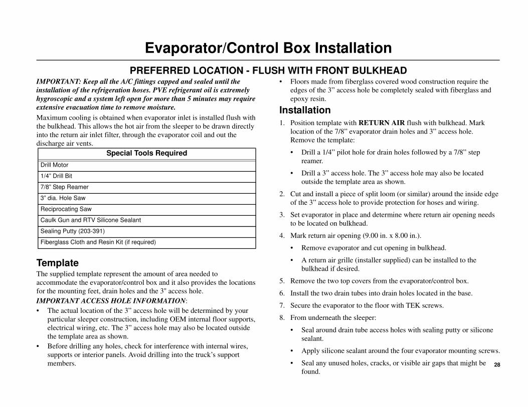
PREFERRED LOCATION - FLUSH WITH FRONT BULKHEADIMPORTANT: Keep all the A/C fittings capped and sealed until the
installation of the refrigeration hoses. PVE refrigerant oil is extremely
hygroscopic and a system left open for more than 5 minutes may require
extensive evacuation time to remove moisture.
Maximum cooling is obtained when evaporator inlet is installed flush with
the bulkhead. This allows the hot air from the sleeper to be drawn directly
into the return air inlet filter, through the evaporator coil and out the
discharge air vents.
TemplateThe supplied template represent the amount of area needed to
accommodate the evaporator/control box and it also provides the locations
for the mounting feet, drain holes and the 3'' access hole.
IMPORTANT ACCESS HOLE INFORMATION:
• The actual location of the 3” access hole will be determined by your
particular sleeper construction, including OEM internal floor supports,
electrical wiring, etc. The 3” access hole may also be located outside
the template area as shown.
• Before drilling any holes, check for interference with internal wires,
supports or interior panels. Avoid drilling into the truck’s support
members.
• Floors made from fiberglass covered wood construction require the
edges of the 3” access hole be completely sealed with fiberglass and
epoxy resin.
Installation
1. Position template with RETURN AIR flush with bulkhead. Mark
location of the 7/8” evaporator drain holes and 3” access hole.
Remove the template:
• Drill a 1/4” pilot hole for drain holes followed by a 7/8” step
reamer.
• Drill a 3” access hole. The 3” access hole may also be located
outside the template area as shown.
2. Cut and install a piece of split loom (or similar) around the inside edge
of the 3” access hole to provide protection for hoses and wiring.
3. Set evaporator in place and determine where return air opening needs
to be located on bulkhead.
4. Mark return air opening (9.00 in. x 8.00 in.).
• Remove evaporator and cut opening in bulkhead.
• A return air grille (installer supplied) can be installed to the
bulkhead if desired.
5. Remove the two top covers from the evaporator/control box.
6. Install the two drain tubes into drain holes located in the base.
7. Secure the evaporator to the floor with TEK screws.
8. From underneath the sleeper:
• Seal around drain tube access holes with sealing putty or silicone
sealant.
• Apply silicone sealant around the four evaporator mounting screws.
• Seal any unused holes, cracks, or visible air gaps that might be
found.
Special Tools Required
Drill Motor
1/4” Drill Bit
7/8” Step Reamer
3” dia. Hole Saw
Reciprocating Saw
Caulk Gun and RTV Silicone Sealant
Sealing Putty (203-391)
Fiberglass Cloth and Resin Kit (if required)

29
Evaporator/Control Box Installation
PREFERRED LOCATION - FLUSH WITH FRONT BULKHEAD
Alternative access hole locations

30
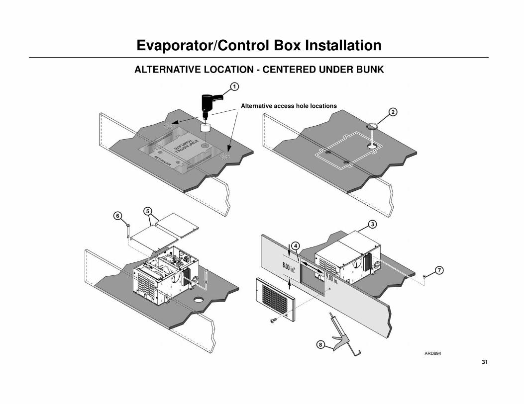
Evaporator/Control Box Installation
ALTERNATIVE LOCATION - CENTERED UNDER BUNK
IMPORTANT: Keep all the A/C fittings capped and sealed until the
installation of the refrigeration hoses. PVE refrigerant oil is extremely
hygroscopic and a system left open for more than 5 minutes may require
extensive evacuation time to remove moisture.
TemplateA template is supplied to represent the amount of area needed to
accommodate the evaporator/control box and the two discharge hoses. It
also provides locations for the four mounting feet, two 7/8” drain holes and
the 3” access hole for routing the refrigerant hoses and electrical harnesses.
IMPORTANT ACCESS HOLE INFORMATION:
• The actual location of the 3” access hole will be determined by your
particular sleeper construction, including OEM internal floor supports,
electrical wiring, etc. The 3” access hole may also be located outside
the template area as shown.
• Before drilling any holes, check for interference with internal wires,
supports or interior panels. Avoid drilling into the truck’s support
members.
• Floors made from fiberglass covered wood construction require the
edges of the 3” access hole be completely sealed with fiberglass and
epoxy resin.
Installation
1. Position the template under the bunk with the RETURN AIR facing
forward. Mark the location of the 7/8”evaporator drain holes and the 3”
access hole. Remove the template:
• Drill 1/4” pilot hole for the drain holes followed by a 7/8”.
• Drill 3” access hole. The 3” access hole may also be located outside
the template area as shown.
2. Cut and install a piece of split loom (or similar) around the inside edge
of the 3” access hole to provide protection for the hoses and wiring.
3. Remove the two top covers from the evaporator/control box.
4. Install the two drain tubes into drain holes located in the base.
5. Secure the evaporator to the floor with TEK screws.
6. Mark return air opening (9.00 in. x 8.00 in.) on the bulkhead.
• A return air grille (installer supplied) can be installed to the
bulkhead if desired.
7. From underneath the sleeper:
• Seal around the drain tube access holes with sealing putty or
silicone sealant.
• Apply silicone sealant around the four evaporator mounting screws.
• Seal any unused holes, cracks, or visible air gaps that might be
found.
Special Tools Required
Drill Motor
1/4” Drill Bit
7/8” Step Reamer
3” dia. Hole Saw
Reciprocating Saw
Caulk Gun and RTV Silicone Sealant
Sealing Putty (203-391)
Fiberglass Cloth and Resin Kit (if required)
31
Evaporator/Control Box Installation
ALTERNATIVE LOCATION - CENTERED UNDER BUNK
Alternative access hole locations
32
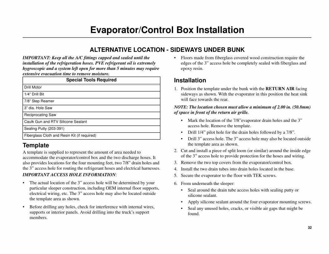
Evaporator/Control Box Installation
ALTERNATIVE LOCATION - SIDEWAYS UNDER BUNK
IMPORTANT: Keep all the A/C fittings capped and sealed until the
installation of the refrigeration hoses. PVE refrigerant oil is extremely
hygroscopic and a system left open for more than 5 minutes may require
extensive evacuation time to remove moisture.
TemplateA template is supplied to represent the amount of area needed to
accommodate the evaporator/control box and the two discharge hoses. It
also provides locations for the four mounting feet, two 7/8” drain holes and
the 3” access hole for routing the refrigerant hoses and electrical harnesses.
IMPORTANT ACCESS HOLE INFORMATION:
• The actual location of the 3” access hole will be determined by your
particular sleeper construction, including OEM internal floor supports,
electrical wiring, etc. The 3” access hole may also be located outside
the template area as shown.
• Before drilling any holes, check for interference with internal wires,
supports or interior panels. Avoid drilling into the truck’s support
members.
• Floors made from fiberglass covered wood construction require the
edges of the 3” access hole be completely sealed with fiberglass and
epoxy resin.
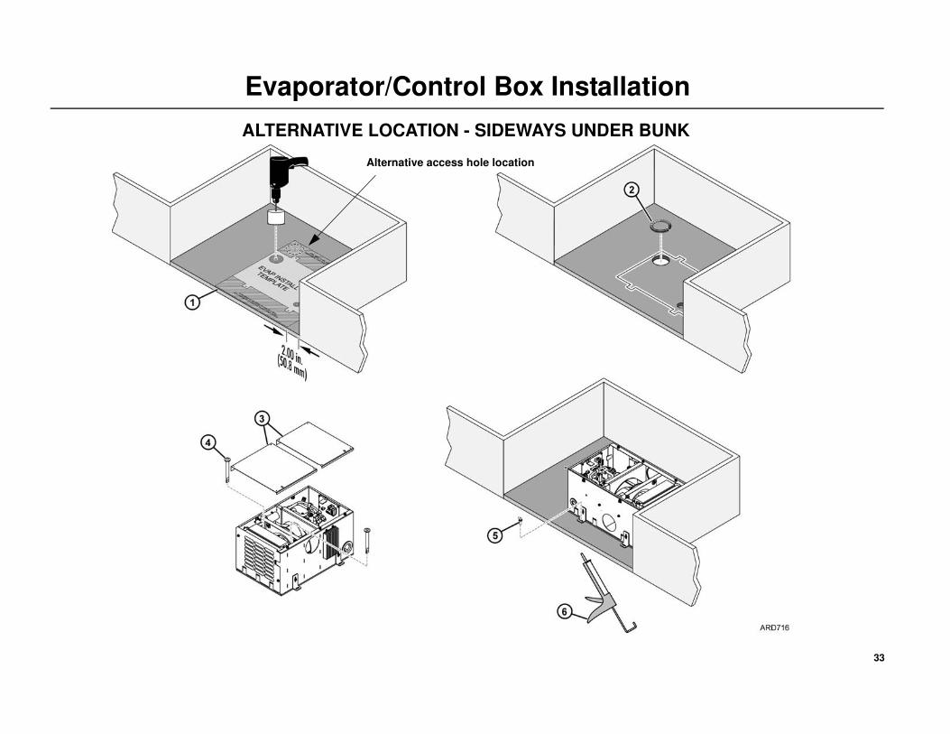
Installation
1. Position the template under the bunk with the RETURN AIR facing
sideways as shown. With the evaporator in this position the heat sink
will face towards the rear.
NOTE: The location chosen must allow a minimum of 2.00 in. (50.8mm)
of space in front of the return air grille.
• Mark the location of the 7/8”evaporator drain holes and the 3”
access hole. Remove the template.
• Drill 1/4” pilot hole for the drain holes followed by a 7/8”.
• Drill 3” access hole. The 3” access hole may also be located outside
the template area as shown.
2. Cut and install a piece of split loom (or similar) around the inside edge
of the 3” access hole to provide protection for the hoses and wiring.
3. Remove the two top covers from the evaporator/control box.
4. Install the two drain tubes into drain holes located in the base.
5. Secure the evaporator to the floor with TEK screws.
6. From underneath the sleeper:
• Seal around the drain tube access holes with sealing putty or
silicone sealant.
• Apply silicone sealant around the four evaporator mounting screws.
• Seal any unused holes, cracks, or visible air gaps that might be
found.
Special Tools Required
Drill Motor
1/4” Drill Bit
7/8” Step Reamer
3” dia. Hole Saw
Reciprocating Saw
Caulk Gun and RTV Silicone Sealant
Sealing Putty (203-391)
Fiberglass Cloth and Resin Kit (if required)
33
Evaporator/Control Box Installation
ALTERNATIVE LOCATION - SIDEWAYS UNDER BUNK
Alternative access hole location

34
Fabricating Refrigeration Hoses
TK 2000 Assembly System
The TK 2000 System is designed for assembly with Multi-Refrigerant hose
only.
Assembly Materials Checklist
• Hose Fitting Tool (204-1045)
• Hose Cutting Tools (204-677)
• TK 2000 Multi-Refrigerant Hose
• Nipple Assembly
• Appropriately Sized Clips and Cage
• POE Refrigerant Oil
NOTE: The two black O-rings on the nipple assembly are of a specific
rubber compound and size. They should not be removed or replaced.
1. Hose
2. Cage
3. Clips
4. Nipple with internal O-ring
12
3
4

35
Fabricating Refrigeration Hoses
Cut the Hose
1. Cut the hose to proper length with an appropriate cutting tool.
Hand-held hose cutter (204-677) has been specially designed for
cutting all non-wire reinforced hose, such as TK 2000
Multi-Refrigerant hose. Be sure the cut is made square to the hose
length.
Slip on Two Clamps
2. Install two proper- size clips onto the cut end of the hose. Orientation of
the clips does not affect the performance of the connection. However
for ease of assembly, both clips should have the same orientation.
CAUTION: Failure to slide the clips over the hose at this time will
require the clips to be stretched over the hose or fitting later.
This may permanently damage the clip.
36
Fabricating Refrigeration Hoses
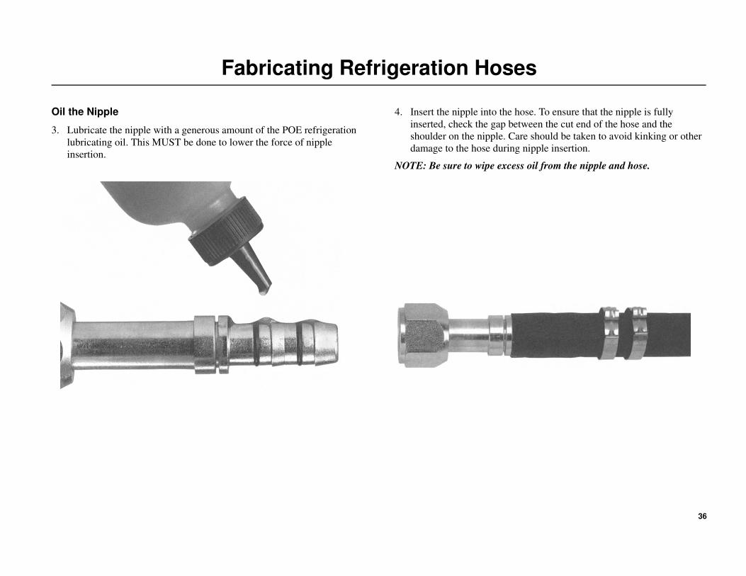
Oil the Nipple
3. Lubricate the nipple with a generous amount of the POE refrigeration
lubricating oil. This MUST be done to lower the force of nipple
insertion.
4. Insert the nipple into the hose. To ensure that the nipple is fully
inserted, check the gap between the cut end of the hose and the
shoulder on the nipple. Care should be taken to avoid kinking or other
damage to the hose during nipple insertion.
NOTE: Be sure to wipe excess oil from the nipple and hose.

37
Fabricating Refrigeration Hoses
Snap on the Cage.
5. Snap the cage into the groove on the nipple. The arms should extend
over the hose length. When the cage has been carefully installed in the
cage grove, the cage will be able to rotate in the grove. This step must
be performed to ensure:
• The clips will be located over the O-ring on the nipple.
• The connection will be compatible with the connection’s pressure
rating.
Slide the Clips
6. Slide the clips over the cage arms and into the channels on each arm.
Close the Clips
7. Use the fitting tool (204-1045 or 204-1128) to close the clips. The
pliers should be positioned squarely on the clip connection points and
should remain square during the closing of the clip.
NOTE: For easiest assembly, the clasp should be closed between the cage
arms.
38
Fabricating Refrigeration Hoses
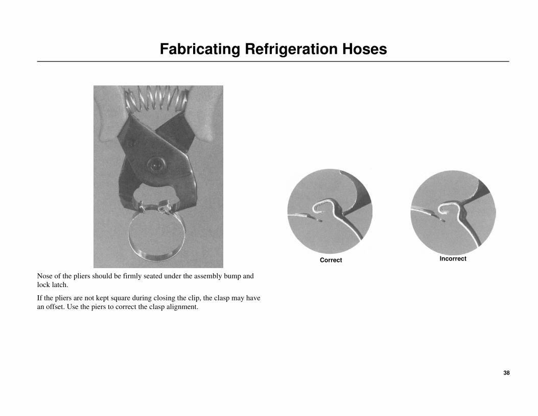
Nose of the pliers should be firmly seated under the assembly bump and
lock latch.
If the pliers are not kept square during closing the clip, the clasp may have
an offset. Use the piers to correct the clasp alignment.
Correct Incorrect

39
Fabricating Refrigeration Hoses
NOTE: Thermo King recommends adherence to all guidelines, including
EPA guidelines concerning the service of refrigerant systems.
CAUTION: TK 2000 Speedy Clip System components should not
be reused. Failure to follow these instructions and/or the use of
TK 2000 Speedy Clip System hose with fittings supplied by other
manufactures could result in sudden or unintended escape of
refrigerant gases. Personal injury and/or violations of EPA
regulations may occur as a consequence.
Improperly
Installed Clip
Properly
Installed Clip

40
A/C Hose Installation
Installation
IMPORTANT: Keep all the A/C fittings capped and sealed until the
installation of the refrigeration hoses. PVE refrigerant oil is extremely
hygroscopic and a system left open for more than 5 minutes may require
extensive evacuation time to remove moisture.
NOTE: The evaporator/control box system has a Nitrogen holding
charge of 5 PSI. This holding charge can safely be vented into the
atmosphere.
NOTE: Read and understand “Fabricating Refrigeration Hoses” on
page 34 for proper hose fabrication requirements. Always use two
wrenches while tightening refrigeration fittings.
Condenser Coil to Evaporator/Control Box
1. Fabricate a #8 hose with a 90 degree fitting and connect to the
#8 fitting on the condenser coil. Tighten the fitting to 15-20 ft-lb
(20-27 N•m).
• Route the hose up through the 3” access hole in the tractor floor and
into the evaporator/control box.
2. Cut the hose to length, install a 45 degree fitting and attach it to the #8
fitting on the compressor. Tighten the fitting to 15 to 20 ft-lb
(20 to 27 N•m).
Receiver Drier to Evaporator/Control Box
3. Fabricate a #6 hose with a 90 degree fitting and attach onto the
OUTLET fitting on the receiver drier. Tighten the fitting to 11 to
13 ft-lb (15 to 17 N•m).
• Route the hose up through the 3” access hole in the tractor floor and
into the evaporator/control box.
4. Cut the hose to length, install a 45 degree fitting and attach onto the #6
fitting on the compressor. Tighten the fitting to 11 to 13 ft-lb
(15 to 17 N•m).
5. Secure all hoses adequately with clamps or band wraps.
Special Tools Required
Hose Fitting Tools (204-1045)
Hose Cutting Tool (204-677)
PAG Refrigerant Oil (203-544)
Torque Wrench
Fitting Size Torque Specifications
#6 (3/8'') 11 to 13 ft-lb (15 to 17 N•m)
#8 (1/2'') 15 to 20 ft-lb (20 to 27 N•m)

41
A/C Hose Installation
42
A/C System Evacuation and Leak Check Procedures
System Evacuation Procedures
IMPORTANT: Always use recommended vacuum equipment. Before
each use, check that there are no leaks in the vacuum equipment either
in the pump itself or in the hoses. The oil in the evacuation station
vacuum pump should be changed after each use.
1. Connect gauge manifold to suction and discharge service ports of
compressor.
2. Connect service line of the gauge manifold to vacuum pump and
micron gauge.
3. Open gauge manifold and vacuum pump valves and gauge manifold
hand valves.
4. Start vacuum pump and evacuate until system reaches 500 microns.
5. Once system reaches 500 microns, continue evacuation for one
additional hour.
6. If it stops in a vacuum continue to evacuate for an additional 30
minutes and recheck. If it stops lower, continue to evacuate system.
NOTE: While the system is being evacuated, continue the installation
with “D2 Heater Installation” on page 44.
7. Close vacuum pump valve, switch off pump, checking that the gauge
reading for the vacuum pump does not exceed 2000 microns in the
following five minutes. If vacuum level exceeds 2000 microns before
five minutes, and continues to rise, proceed to the Leak Check
Procedures section. If it stops in a vacuum continue to evacuate for an
additional 30 minute.s
8. If vacuum level remains below 2000 microns for 5 minutes the system
is leak free and ready to be filled with refrigerant.
9. Close manifold hand valves and remove evacuation equipment.
Leak Check Procedures
1. Add vapor R-134a to the unit until bottle pressure is reached.
2. Thoroughly leak check the system with an electronic leak detector.
3. If leak(s) are found, recover leak check charge.
4. Repair any leaks and re-evacuate system.
Special Tools Required
Vacuum Pump (204-713) or equivalent
Micron Gauge (204-720) or equivalent
Electronic Leak Detector (204-756)
Gauge Set with R134a Adapters

43
A/C System Evacuation and Leak Check Procedures
44
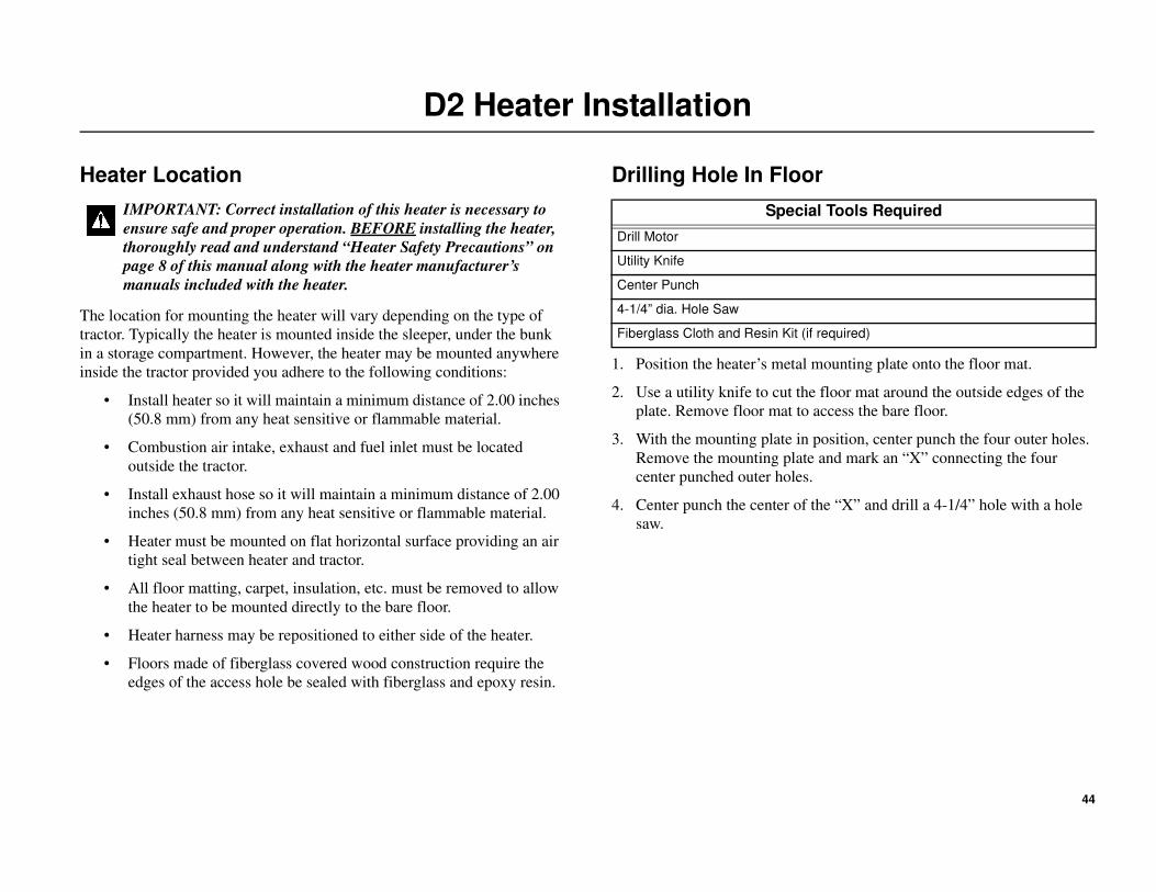
D2 Heater Installation
Heater Location
The location for mounting the heater will vary depending on the type of
tractor. Typically the heater is mounted inside the sleeper, under the bunk
in a storage compartment. However, the heater may be mounted anywhere
inside the tractor provided you adhere to the following conditions:
• Install heater so it will maintain a minimum distance of 2.00 inches
(50.8 mm) from any heat sensitive or flammable material.
• Combustion air intake, exhaust and fuel inlet must be located
outside the tractor.
• Install exhaust hose so it will maintain a minimum distance of 2.00
inches (50.8 mm) from any heat sensitive or flammable material.
• Heater must be mounted on flat horizontal surface providing an air
tight seal between heater and tractor.
• All floor matting, carpet, insulation, etc. must be removed to allow
the heater to be mounted directly to the bare floor.
• Heater harness may be repositioned to either side of the heater.
• Floors made of fiberglass covered wood construction require the
edges of the access hole be sealed with fiberglass and epoxy resin.
Drilling Hole In Floor
1. Position the heater’s metal mounting plate onto the floor mat.
2. Use a utility knife to cut the floor mat around the outside edges of the
plate. Remove floor mat to access the bare floor.
3. With the mounting plate in position, center punch the four outer holes.
Remove the mounting plate and mark an “X” connecting the four
center punched outer holes.
4. Center punch the center of the “X” and drill a 4-1/4” hole with a hole
saw.
IMPORTANT: Correct installation of this heater is necessary to
ensure safe and proper operation. BEFORE installing the heater,
thoroughly read and understand “Heater Safety Precautions” on
page 8 of this manual along with the heater manufacturer’s
manuals included with the heater.
Special Tools Required
Drill Motor
Utility Knife
Center Punch
4-1/4” dia. Hole Saw
Fiberglass Cloth and Resin Kit (if required)

45
D2 Heater Installation

46
D2 Heater Installation
Heater Subassembly
Turn the heater upside down and attach the following components:
1. Snap the Air Outlet Hood onto the end of the heater.
2. Install the mounting plate with nuts and lock washers and tighten
securely.
3. Attach the short rubber hose and clamps onto the fuel inlet connection
located at the base of the heater.
4. Insert the plastic fuel line all the way into the rubber hose until it
bottoms out to prevent air gaps. Tighten both hose clamps securely.
NOTE: The exhaust and intake hose are not interchangeable.
They are different in size, type of clamps and end caps. Make sure the
correct hose and clamp is installed on the proper heater fitting. All
clamps must be turned to the center to allow clearance to go through the
4-1/2” mounting hole.
5. Attach the silver exhaust hose and metal clamp onto the fitting
located under the OUTLET end of the heater. Turn metal clamp to the
center and tighten securely.
6. Attach the black air intake hose and hose clamp onto the fitting
located under the INLET end of the heater. Turn hose clamp to the
center and tighten securely.
7. Install gasket to mounting plate.
8. The heater has two service data nameplates. Remove one and reinstall
it onto the top of the heater so that it is visible when the heater is
installed.
Heater Installation
9. Position the heater over the access hole with intake hose, exhaust hose
and fuel line exiting the tractor.
10. Attach the heater to the floor with TEK screws and tighten securely.
NOTE: Tighten TEK screws sufficiently to ensure a positive seal between
mounting plate and mounting surface. Do not over tighten!
11. From underneath the sleeper:
• Apply silicone sealant around ONLY the four heater mounting
screws. DO NOT apply any sealant around the access hole!

47
D2 Heater Installation
48
D2 Heater Installation
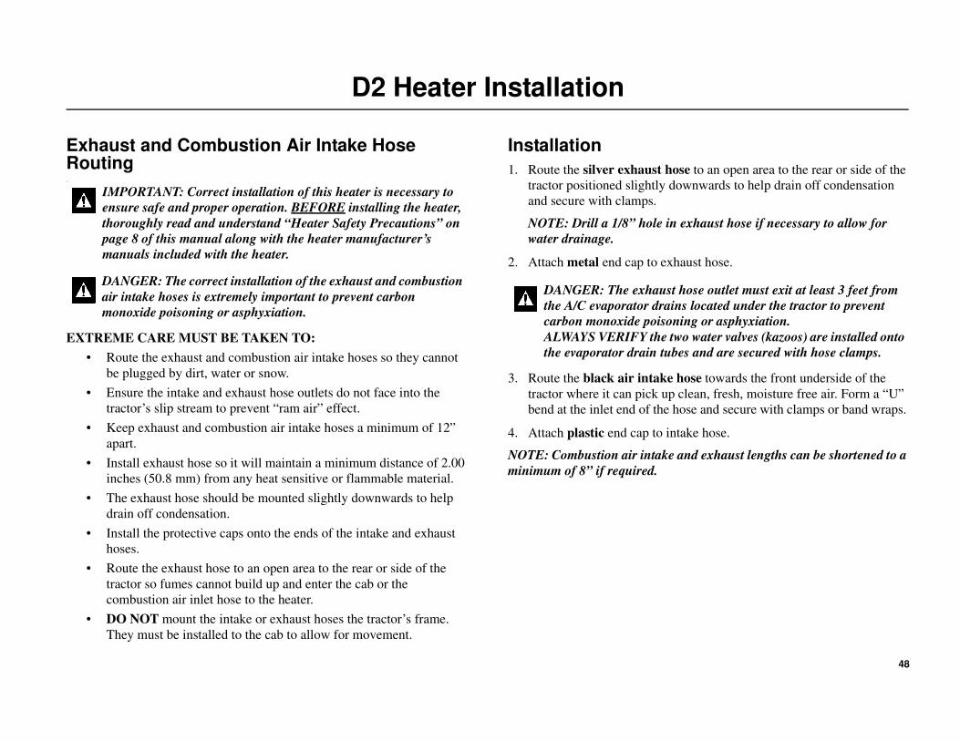
Exhaust and Combustion Air Intake Hose Routing.
EXTREME CARE MUST BE TAKEN TO:
• Route the exhaust and combustion air intake hoses so they cannot
be plugged by dirt, water or snow.
• Ensure the intake and exhaust hose outlets do not face into the
tractor’s slip stream to prevent “ram air” effect.
• Keep exhaust and combustion air intake hoses a minimum of 12”
apart.
• Install exhaust hose so it will maintain a minimum distance of 2.00
inches (50.8 mm) from any heat sensitive or flammable material.
• The exhaust hose should be mounted slightly downwards to help
drain off condensation.
• Install the protective caps onto the ends of the intake and exhaust
hoses.
• Route the exhaust hose to an open area to the rear or side of the
tractor so fumes cannot build up and enter the cab or the
combustion air inlet hose to the heater.
• DO NOT mount the intake or exhaust hoses the tractor’s frame.
They must be installed to the cab to allow for movement.
Installation
1. Route the silver exhaust hose to an open area to the rear or side of the
tractor positioned slightly downwards to help drain off condensation
and secure with clamps.
NOTE: Drill a 1/8” hole in exhaust hose if necessary to allow for
water drainage.
2. Attach metal end cap to exhaust hose.
3. Route the black air intake hose towards the front underside of the
tractor where it can pick up clean, fresh, moisture free air. Form a “U”
bend at the inlet end of the hose and secure with clamps or band wraps.
4. Attach plastic end cap to intake hose.
NOTE: Combustion air intake and exhaust lengths can be shortened to a
minimum of 8” if required.
IMPORTANT: Correct installation of this heater is necessary to
ensure safe and proper operation. BEFORE installing the heater,
thoroughly read and understand “Heater Safety Precautions” on
page 8 of this manual along with the heater manufacturer’s
manuals included with the heater.
DANGER: The correct installation of the exhaust and combustion
air intake hoses is extremely important to prevent carbon
monoxide poisoning or asphyxiation.
DANGER: The exhaust hose outlet must exit at least 3 feet from
the A/C evaporator drains located under the tractor to prevent
carbon monoxide poisoning or asphyxiation.
ALWAYS VERIFY the two water valves (kazoos) are installed onto
the evaporator drain tubes and are secured with hose clamps.

49
D2 Heater Installation

50
D2 Heater Duct Installation
Duct Locations
The heater is equipped with a Return Inlet and Discharge Outlet for
attaching the flexible heater duct hoses.
IMPORTANT: A return air duct to the heater should be provided for best
heating efficiency.
• Return Inlet must be provided to return air to the heater. It is
typically mounted at the base of the bunk directly opposite the
discharge outlet vent.
• Discharge Outlet should be located at floor level to provide
maximum heating comfort in the sleeper. It is typically installed at
the base of the bunk on one end.
• Heater ducts should be installed and routed with smooth bends and
no kinks to provide maximum airflow.
Installation
Discharge Air
1. Find an appropriate location for the floor level discharge air vent and
drill a 2-1/2” hole using the correct hole saw.
• Unsnap rotating outer louver assembly from the mounting base.
• Install the base into 2-1/2” hole and secure with supplied screws.
• Reinstall rotating outer louver assembly back into the mounting
base ring. Verify that it rotates freely.
2. Attach one end of the heater duct to the discharge outlet hood on the
heater and secure with supplied clamp.
3. Route the heater duct to the floor level discharge air vent, cut as
needed, attach to the end of the plastic louver vent and secure with
supplied hose clamp.
Return Air
4. If a return air duct is not used, the protective grille must be installed
onto the heater outlet.
5. Find an appropriate location for the floor level return air grille and
drill a 2-1/2” hole using the correct hole saw.
• Install the return air grille into the 2-1/2” hole and secure with
supplied screws.
6. Attach one end of the return air duct to the air inlet hood on the heater
and secure with supplied clamp.
• Route the return air duct to the return air grille, cut as needed,
attach to the end of the plastic louver vent and secure with supplied
hose clamp.
CAUTION:
• USE SUPPLIED HEATER DUCT HOSE ONLY!
Do not use existing vehicle ducts or outlets. Ducts and
outlets must be capable of withstanding a minimum of
300F (148.9C) operating temperatures.
• Adjustable air vent must always be installed so it cannot
blow hot air directly at living creatures (people, animals)
or objects sensitive to temperature.
• Do not position outlet so that it will blow hot air directly at
operator or at thermostat.
• Position air outlet so that it cannot be obstructed.
• Use the supplied protective air intake grille on the air inlet
side of the heater to prevent objects from being sucked in.
• Do not overtighten duct clamps.
• DO NOT lay or bundle the heater ducts with A/C ducts.
They should not touch each other.
• Ensure provisions are made for proper air return
ventilation.
Special Tools Required
Drill Motor
2-1/2” Hole Saw (for installing discharge air vent and return air grille)
3” Hole Saw (for routing ducts through compartment walls if required)

51
D2 Heater Duct Installation

52
D4 High Output Heater Installation (Option)
Heater Location
The location for mounting the heater will vary depending on the type of
tractor. Typically the heater is mounted inside the sleeper, under the bunk
in a storage compartment. However, the heater may be mounted anywhere
inside the tractor provided you adhere to the following conditions:
• Install heater so it will maintain a minimum distance of 2.00 inches
(50.8 mm) from any heat sensitive or flammable material.
• Combustion air intake, exhaust and fuel inlet must be located
outside the tractor.
• Install exhaust hose so it will maintain a minimum distance of 2.00
inches (50.8 mm) from any heat sensitive or flammable material.
• Heater must be mounted on flat horizontal surface providing an air
tight seal between heater and tractor.
• All floor matting, carpet, insulation, etc. must be removed to allow
the heater to be mounted directly to the bare floor.
• Heater harness may be repositioned to either side of the heater.
• Floors made of fiberglass covered wood construction require the
edges of the access hole be sealed with fiberglass and epoxy resin.
Drilling Hole In Floor
1. Position the heater’s metal mounting plate onto the floor mat.
2. Use a utility knife to cut the floor mat around the outside edges of the
plate. Remove floor mat to access the bare floor.
3. With the mounting plate in position, center punch the four outer holes.
Remove the mounting plate and mark an “X” connecting the four
center punched outer holes.
4. Center punch the center of the “X” and drill a 4-1/4” hole with a hole
saw.
IMPORTANT: Correct installation of this heater is necessary to
ensure safe and proper operation. BEFORE installing the heater,
thoroughly read and understand “Heater Safety Precautions” on
page 8 of this manual along with the heater manufacturer’s
manuals included with the heater.
Special Tools Required
Drill Motor
Utility Knife
Center Punch
4-1/4” dia. Hole Saw
Fiberglass Cloth and Resin Kit (if required)

53
D4 High Output Heater Installation (Option)

54
D4 High Output Heater Installation (Option)
Heater Subassembly
Turn the heater upside down and attach the following components:
1. Snap the Air Outlet Hood onto the end of the heater.
2. Install the mounting plate with nuts and lock washers and tighten
securely.
3. Attach the short rubber hose and clamps onto the fuel inlet connection
located at the base of the heater.
4. Insert the plastic fuel line all the way into the rubber hose until it
bottoms out to prevent air gaps. Tighten both hose clamps securely.
NOTE: The exhaust and intake hose are not interchangeable.
They are different in size, type of clamps and end caps. Make sure the
correct hose and clamp is installed on the proper heater fitting. All
clamps must be turned to the center to allow clearance to go through the
4-1/2” mounting hole.
5. Attach the silver exhaust hose and metal clamp onto the fitting
located under the OUTLET end of the heater. Turn metal clamp to the
center and tighten securely.
6. Attach the black air intake hose and hose clamp onto the fitting
located under the INLET end of the heater. Turn hose clamp to the
center and tighten securely.
7. Install gasket to mounting plate.
8. The heater has two service data nameplates. Remove one and reinstall
it onto the top of the heater so that it is visible when the heater is
installed.
Heater Installation
9. Position the heater over the access hole with intake hose, exhaust hose
and fuel line exiting the tractor.
10. Attach the heater to the floor with TEK screws and tighten securely.
NOTE: Tighten TEK screws sufficiently to ensure a positive seal between
mounting plate and mounting surface. Do not over tighten!
11. From underneath the sleeper:
• Apply silicone sealant around ONLY the four heater mounting
screws. DO NOT apply any sealant around the access hole!

55
D4 High Output Heater Installation (Option)

56
D4 High Output Heater Installation (Option)
Exhaust and Combustion Air Intake Hose Routing
EXTREME CARE MUST BE TAKEN TO:
• Route the exhaust and combustion air intake hoses so they cannot
be plugged by dirt, water or snow.
• Ensure the intake and exhaust hose outlets do not face into the
tractor’s slip stream to prevent “ram air” effect.
• Keep exhaust and combustion air intake a minimum of 12” apart.
• Install exhaust hose so it will maintain a minimum distance of 2.00
inches (50.8 mm) from any heat sensitive or flammable material.
• The exhaust tube should be mounted slightly downwards to help
drain off condensation.
• Install the protective caps. onto the ends of the intake and exhaust
hoses.
• Route the exhaust tube to an open area to the rear or side of the
tractor so fumes cannot build up and enter the cab or the
combustion air inlet hose to the heater.
• DO NOT mount the intake or exhaust hoses the tractor’s frame.
They must be installed to the cab to allow for movement.
Installation
1. Route the silver exhaust hose to an open area to the rear or side of the
tractor positioned slightly downwards to help drain off condensation
and secure with clamps.
NOTE: Drill a 1/8” hole in exhaust hose if necessary to allow for
water drainage.
2. Attach metal end cap to exhaust hose.
3. Route the black air intake hose towards the front underside of the
tractor where it can pick up clean, fresh, moisture free air. Form a “U”
bend at the inlet end of the hose and secure with clamps or band wraps.
4. Attach plastic end cap to intake hose.
NOTE: Combustion air intake and exhaust lengths can be shortened to a
minimum of 8” if required.
IMPORTANT: Correct installation of this heater is necessary to
ensure safe and proper operation. BEFORE installing the heater,
thoroughly read and understand “Heater Safety Precautions” on
page 8 of this manual along with the heater manufacturer’s
manuals included with the heater.
DANGER: The correct installation of the exhaust and combustion
air intake hoses is extremely important to prevent carbon
monoxide poisoning or asphyxiation.
DANGER: The exhaust hose outlet must exit at least 3 feet from
the A/C evaporator drains located under the tractor to prevent
carbon monoxide poisoning or asphyxiation.
ALWAYS VERIFY the two water valves (kazoos) are installed onto
the evaporator drain tubes and are secured with hose clamps.

57
D4 High Output Heater Installation (Option)

58
D4 High Output Heater Duct Installation (Option)
Duct Locations
The heater is equipped with a Return Inlet and Discharge Outlet for
attaching the flexible heater duct hoses.
IMPORTANT: A return air duct to the heater should be provided for best
heating efficiency.
• Return Inlet must be provided to return air to the heater. It is
typically mounted at the base of the bunk directly opposite the
discharge outlet vent.
• Discharge Outlet should be located at floor level to provide
maximum heating comfort in the sleeper. It is typically installed at
the base of the bunk on one end.
• Heater ducts should be installed and routed with smooth bends and
no kinks to provide maximum airflow.
Installation
Discharge Air
1. Find an appropriate location for the floor level discharge air vent and
drill a 4” hole using the correct hole saw.
• Unsnap rotating outer louver assembly from the mounting base.
• Install the base into 4” hole and secure with supplied screws.
• Reinstall rotating outer louver assembly back into the mounting
base ring. Verify that it rotates freely.
2. Attach one end of the heater duct to the discharge outlet hood on the
heater and secure with supplied clamp.
3. Route the heater duct to the floor level discharge air vent, cut as
needed, attach to the end of the plastic louver vent and secure with
supplied hose clamp.
Return Air
4. If a return air duct is not used, the protective grille must be installed
onto the heater outlet.
5. Find an appropriate location for the floor level return air grille and
drill a 4” hole using the correct hole saw.
• Install the return air grille into the 4” hole and secure with supplied
screws.
6. Attach one end of the return air duct to the air inlet hood on the heater
and secure with supplied clamp.
7. Route the return air duct to the return air grille, cut as needed, attach to
the end of the plastic louver vent and secure with supplied hose clamp.
CAUTION:
• USE SUPPLIED HEATER DUCT HOSE ONLY!
Do not use existing vehicle ducts or outlets. Ducts and
outlets must be capable of withstanding a minimum of
300F (148.9C) operating temperatures.
• Adjustable air vent must always be installed so it cannot
blow hot air directly at living creatures (people, animals)
or objects sensitive to temperature.
• Do not position outlet so that it will blow hot air directly at
operator or at thermostat.
• Position air outlet so that it cannot be obstructed.
• Use the supplied protective air intake grille on the air inlet
side of the heater to prevent objects from being sucked in.
• Do not overtighten duct clamps.
• DO NOT lay or bundle the heater ducts with A/C ducts.
They should not touch each other.
• Ensure provisions are made for proper air return
ventilation.
Special Tools Required
Drill Motor
4” Hole Saw (for installing discharge air vent, return air grille and for routing
ducts through compartment walls if required

59
D4 High Output Heater Duct Installation (Option)

60
A/C Duct Installation
A/C Vent Locations
The evaporator is equipped with two air discharge outlets to attach the
supplied flexible air ducts. The ducts will be attached to plastic air vents
that should be located and installed to provide maximum air circulation in
the sleeper. Suggested locations of the air vents:
• MEDIUM (above lower bunk level)
• HIGH (above upper bunk level)
• Alternative Location - LOW (floor level)
NOTE: A/C air ducts and vents are typically routed and installed through
closets or storage compartments.
IMPORTANT: Extreme care should always be taken when drilling holes
in the various types of material found in sleepers such as plastic, steel,
aluminum, and upholstery.
Installation
1. From inside the evaporator, install the short style hose adapters into
each air discharge outlet.
For Side Mounted Evaporators - Unsnap the rotating outer louver
assembly from the hose adapter, reinstall the louver into a short style
hose adapter and install it into the front air discharge outlet. Install a
short style hose dapper into the rear air discharge outlet.
2. Find appropriate locations for the A/C vent(s) inside the sleeper and
drill 4-1/4” diameter hole(s).
3. Attach the flexible air duct onto hose adapter(s) and secure with a
supplied hose clamp.
4. Route the flexible air duct through the A/C vent hole. Cut excess duct
as needed.
5. Unsnap rotating outer louver assembly from the mounting base.
6. Attach to flexible air duct to the end of the hose adapter with band
wraps.
7. Push the hose adapter back into 4-1/4” mounting hole and secure with
supplied screws.
8. Reinstall rotating outer louver assembly back into the hose adapter and
verify that it rotates freely.
9. Verify flexible ducts are installed and routed with smooth bends and no
kinks to provide maximum airflow.
10. Secure flexible ducts with large band wraps to prevent excess
movement.
Special Tools Required
Drill Motor
4-1/4” diameter Hole Saw (for installing plastic A/C louver vents and for routing
ducts through compartment walls)
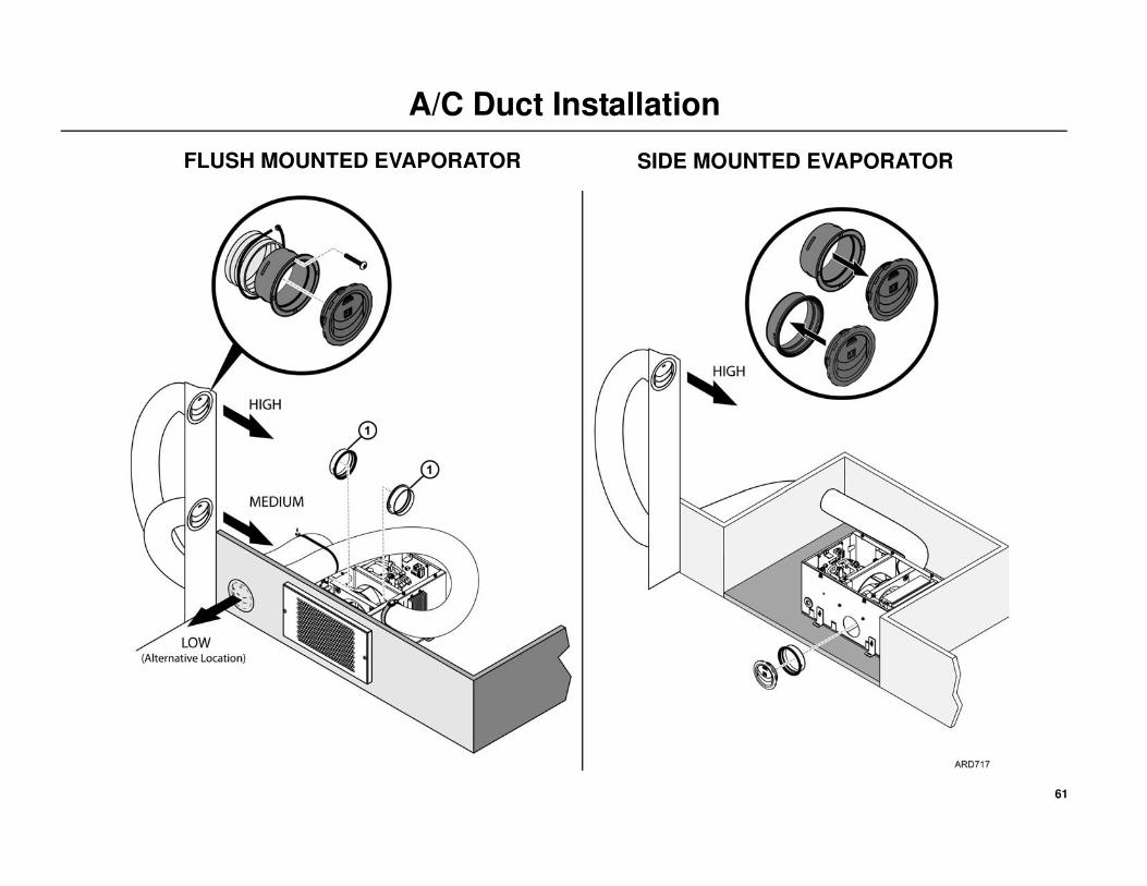
61
A/C Duct Installation
SIDE MOUNTED EVAPORATORFLUSH MOUNTED EVAPORATOR

62
Main Harness Installation
Installation
IMPORTANT: Before making any electrical connections, confirm the
heater and battery cables are not connected to the batteries.
NOTE: Excessive harnesses lengths should be doubled up and secured
with band wraps. DO NOT CUT THE WIRE HARNESSES!
NOTE: Always check the male pins for straightness before attempting to
mate connectors. If any resistance is felt when mating the connector:
recheck the male pin alignment. Exercise care when mating the
connections to circuit boards.
Route the two (2) main harnesses attached to the battery box up through the
3” access hole in the tractor floor and into the evaporator/control box.
Compressor Controller Board
1. Connect the 28V terminal lug to the stud marked POS. Tighten the nut
to 18 in-lbs.(2.0 N•m).
2. Connect the CH02 terminal lug to the stud marked NEG. Tighten the
nut to 18 in-lbs.(2.0 N•m).
IMPORTANT: Make sure the two terminal lugs are not touching each
other!
Main Controller Board
3. Connect the #2 terminal lug to stud marked 2. Tighten the nut to
18 in-lbs.(2.0 N•m).
4. Connect the CH01 terminal lug to stud marked CH. Tighten the nut to
20 in-lbs.(2.25 N•m).
5. Connect the 20-pin connector to BATT BOX (J37) connection.

63
Main Harness Installation
Main
Controller
Board
Compressor
Controller
Board
CH
2
J37

64
Condenser Fan and Sensor Harness Installation
Installation
IMPORTANT: Before making any electrical connections, confirm the
Heater and battery cables are not connected to the batteries.
NOTE: Excessive harnesses lengths should be doubled up and secured
with band wraps. DO NOT CUT THE WIRE HARNESSES!
NOTE: Always check the male pins for straightness before attempting to
mate connectors. If any resistance is felt when mating the connector:
recheck the male pin alignment. Exercise care when mating the
connections to circuit boards.
Main Controller Board
Locate the Condenser Fan and Sensor harness supplied loose in the
installation kit. Make the following connections at the Main Controller
Board located inside the evaporator/control box:
1. Connect the 6-pin connector to the COND FAN (J59) connector pins.
2. Route the harness down through the 3” access hole in the tractor floor
and out to the condenser fan.
3. Connect the 4-pin connector to the matting connector on the condenser
fan.
4. Attach the Ambient Air Sensor to the inside of the receiver drier
bracket with the supplied clamp and mounting hardware. NOTE:
Always install the sensor to the inside of the drier bracket for best
temperature readings and to protect it from damage.
5. Secure all harness adequately with insulated clamps or band wraps.

65
Condenser Fan and Sensor Harness Installation
Main
Controller
Board
J59

66
Ignition Switch and Harness Installation
Installation
IMPORTANT: The Ignition Sense harness wire must be connected to the
ON or RUN position of the tractor’s ignition switch. This will prevent the
APU from operating when the tractor’s engine is running.
Locate the Ignition Sense harness supplied loose in the installation kit.
1. Connect end of the harness without the diode and fuse to the IGN
connector pin (J70) on the Main Controller Board inside the
evaporator/control box.
2. Route the harness out of the rubber grommet on the side of the
evaporator/control box towards the tractor’s ignition switch.
3. Connect the end with the diode and fuse to the ON or RUN position of
the tractor’s ignition switch.
4. Secure the harness adequately with band wraps.

67
Ignition Switch and Harness Installation
Main
Controller
Board
IGN

68
HMI Installation
HMI Controller Location
Choose a location inside the tractor’s sleeper for the HMI controller that is
easily accessible and visible from the drivers bunk.
Installation
Locate the HMI Controller Harness with the 8-pin connectors on each
end supplied loose in the installation kit.
1. Route the harness into the evaporator /control box through the rubber
grommet on the side.
2. Connect the 8-pin connector to the HMI connector (J34) on the Main
Controller Board.
3. From the evaporator/control box, route the harness behind the interior
walls (if applicable) to the location chosen to install the HMI controller.
4. Unsnap the rear mounting base from the controller and route the
harness connector through the access hole.
• Position and level the mounting base and install securely.
5. Push the connector firmly into the rear of the controller and snap the
controller back onto the mounting base.
Special Tools Required
Level
Drill Motor
Drill Bits

69
HMI Installation
Main Controller
Board
J34

70
Heater Harness Installation
Installation
Locate the Heater Harness supplied loose in the installation kit. Remove
the two small plastic bags attached to the harness containing the fuel pump
electrical connector components and the in-line fuse assembly. Retain these
for installation later.
1. Connect the 14-pin connector (with the locking tab) to the mating
connector on the heater:
• use a large bladed screwdriver to pull the locking tab out
(to unlock) from the connector body.
• connect the two connectors together.
• push locking tab back in (to lock) the connector body.
2. Route the other 14-pin connector and the 2-pin connector into the
evaporator/control box through the rubber grommet on the side.
3. Connect the 14-pin connector to the HEATER CONTROL (J54)
connection on the Main Controller Board.
4. Connect the 2-pin power wire connector to the HEATER POWER
(J65) connection on the Main Controller Board.
5. Route the fuel pump harness out of the sleeper through the 3” access
hole. It will be assembled and connected to the fuel pump in a later
step.
NOTE: The Diagnostic Connector is only used for diagnostic purposes.
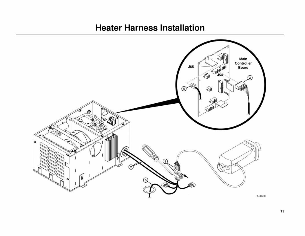
71
Heater Harness Installation
Main
Controller
Board
J54
J65

72
Auxiliary AC Power Accessories (Optional)
1000 Watt Pure Sine Wave Power Inverter OnlyFollow the detailed installation instructions (TK-54590-19-IM) supplied with the 1000 Watt Power Inverter.
AC/DC Power Converter OnlyFollow the detailed installation instructions (TK-54590-19-IM) supplied with the AC/DC Power Converter.
Dual System - 1000 Watt Pure Sine Wave Power Inverter and
AC/DC Power ConverterFollow the detailed installation instructions (TK-54590-19-IM) supplied with the 1000 Watt Power Inverter and AC/DC Power Converter.

73
Auxiliary AC Power Accessories (Optional)
Tractor’s Batteries Tractor’s Batteries Tractor’s Batteries
Power Inverter Only Power Converter Only Both
IMPORTANT:
The tractor’s battery power
cables must always be
connected directly to the
POWER INVERTER.

74
Fuel Pickup Tube Installation
DIRECT TANK INSTALLATION - NO DRILLING
OEM Fuel Tank Fittings
NOTE: Some fuel tanks may have auxiliary fuel connections or 1/4''
NPT connections factory installed. These fitting eliminate the need to
drill into the fuel tank to install the heater’s fuel pickup tube.
• OEM Fuel Connections - Route and connect the heater’s fuel
supply line to one of these fittings.
• OEM 1/4'' NPT Fitting - See following installation instructions.
Important Installation Tips
• Remove the protective caps from the ends of the pickup tube prior
to installation.
• Do not apply any type of sealant material to the fuel pickup tube
assembly. Doing so will result in plugged fuel lines.
Installation
NOTE: The tank mounted fuel pump bracket cannot be used on direct
tank installations. The supplied remote mounted L-bracket must be used.
1. Remove the nut, washers and bushing assembly from the fuel pickup
tube as shown. The nut, washers and bushing assembly will not be
used.
2. Remove the 1/4'' NPT fitting from fuel pickup tube and install it into
the fuel tank’s 1/4'' NPT fitting securely.
3. Measure the fuel tank diameter and cut the pickup tube 3” shorter.
4. Install the pickup tube with the ferrule nut into the tank.
• Position the pickup tube as needed to facilitate fuel line connections
and tighten ferrule nut securely.
5. Install the supplied warning nameplate onto the fuel tank in a visible
area near the fuel cap.
DANGER: Use caution when working in or around the area of
the diesel fuel tank. Diesel fuel vapors are potentially explosive.
Do not smoke while working near the diesel fuel tank.
Special Tools Required
Tape Measure
Tubing Cutter
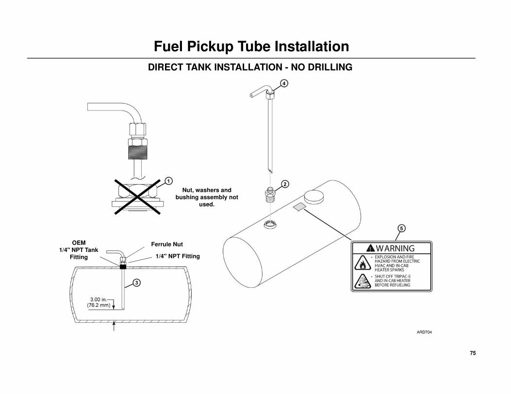
75
Fuel Pickup Tube Installation
DIRECT TANK INSTALLATION - NO DRILLING
Nut, washers and
bushing assembly not
used.
Ferrule Nut
1/4'' NPT Fitting
OEM
1/4'' NPT Tank
Fitting

76
Fuel Pickup Tube Installation
ALTERNATIVE INSTALLATION - DRILLING HOLE IN FUEL TANKInstalling the Fuel Pickup Tube
Important Installation Tips• Check for internal baffles inside the fuel tank BEFORE drilling any
holes.
• Remove protective caps from ends of pickup tube prior to
installation.
• Do not apply any type of sealant material to the fuel pickup tube
assembly. Doing so will result in plugged fuel lines.
• The ferrule nut and 1/4'' NPT fitting must be tightened securely into
the bushing before installing the pickup tube into the tank. Failure
to tighten the fittings will allow the bushing and washer assembly
to slide down the pickup tube and drop into the fuel tank.
Installation
1. Measure and mark the mounting holes on the fuel tank as shown.
2. Drill (2) 0.25'' outer holes first followed by the 1.00'' center hole.
• Thoroughly clean and flush the tank to remove any chips.
3. Measure the fuel tank diameter and cut the pickup tube 3” shorter.
• With the pickup tube positioned at the correct height, place a
wrench on the flats of the bushing and tighten the 1/4'' NPT fitting
and the ferrule nut securely.
4. Remove the large nut, metal cupped washer and rubber washer from
the bushing assembly.
• Insert the fuel pickup tube (with the reinforcing washer) into the
tank using the slot created by the two 0.25'' holes.
• Lift the pickup tube and bushing into position through the 1.00''
hole.
• Hold the pickup tube in place and reinstall the rubber washer, metal
cupped washer, fuel pump bracket and large nut onto the bushing.
Hand tighten the large nut.
• Position the pickup tube as needed to facilitate fuel line
connections.
• Place a wrench on the flats of the bushing and tighten the large nut
securely.
5. Install the supplied warning nameplate onto the fuel tank in a visible
area near the fuel cap.
DANGER: Use caution when working in or around the area of
the diesel fuel tank. Diesel fuel vapors are potentially explosive.
Do not smoke while working near the diesel fuel tank.
DANGER: Before drilling into a fuel tank, drain all fuel from the
tank. Use nitrogen or an inert gas to purge the diesel fuel vapors
from the tank. Keep the diesel tank filled with inert gas while
drilling.
DANGER: Use extreme caution when drilling into a diesel fuel
tank. Sparks from an electric drill or drill bit could cause an
explosion.
Special Tools Required
Tape Measure
Drill Motor
1/4'' and 1'' Drill Bits
Tubing Cutter

77
Fuel Pickup Tube Installation
ALTERNATIVE INSTALLATION - DRILLING HOLE IN FUEL TANK
Fuel Pump BracketFerrule Nut
1/4'' NPT FittingBushing
IMPORTANT:
The ferrule nut and 1/4'' NPT fitting must be
tightened securely into the bushing before
installing the pickup tube into the tank.

78
Heater Fuel Pump and Fuel Line Installation
Installation
Tank Mounted Fuel Pump
1. Install the fuel pump and rubber clamp onto the tank mounted bracket
securely.
2. Attach a fuel line hose from the fuel pick-up supply to the inlet end of
the fuel pump and secure with supplied hose clamps.
3. Attach the short rubber hose connection to the outlet end of the fuel
pump and secure with supplied hose clamps.
4. Route the plastic fuel line (installed earlier on the heater) to the fuel
pump and cut to length. Insert the fuel line into the rubber hose
connection until it butts up tight with the fuel pump’s outlet pipe.
Secure with supplied hose clamp.
• The fuel line must be installed correctly to prevent air bubbles
(DETAIL A).
• The fuel line from the pickup tube, to fuel pump, to heater should
be routed at a continuous rise.
• Only use a hose cutter or utility knife to cut plastic fuel lines. Do
not use a wire cutter as this will pinch the plastic fuel line closed.
Remote Mounted Fuel Pump with L-Bracket
Choose a protected location under the cab close to the fuel pick-up tube
and heater and install the supplied L-bracket securely with TEK screws.
1. Install the fuel pump into the rubber mounting clamp and then onto the
L-bracket.
2. Position the fuel pump at a 15 to 35 degree angle with the outlet end
facing up (outlet end has connector and smaller barb fitting) and tighten
mounting hardware securely.
3. Attach the short rubber hose connection to the outlet end of the fuel
pump and secure with supplied hose clamp.
4. Route the plastic fuel line (installed earlier on the heater) to the fuel
pump and cut to length. Insert the fuel line into the rubber hose
connection until it butts up tight with the fuel pump’s outlet pipe.
Secure with supplied hose clamp.
• The fuel line must be installed correctly to prevent air bubbles
(DETAIL A).
• The fuel line from the pickup tube, to fuel pump, to heater should
be routed at a continuous rise.
• Only use a hose cutter or utility knife to cut plastic fuel lines. Do
not use a wire cutter as this will pinch the plastic fuel line closed.
5. Attach fuel line from the fuel pick-up supply to the inlet end of the fuel
pump and secure with supplied hose clamps.
Special Tools Required
Utility Knife
Hose Cutting Tool (204-677)
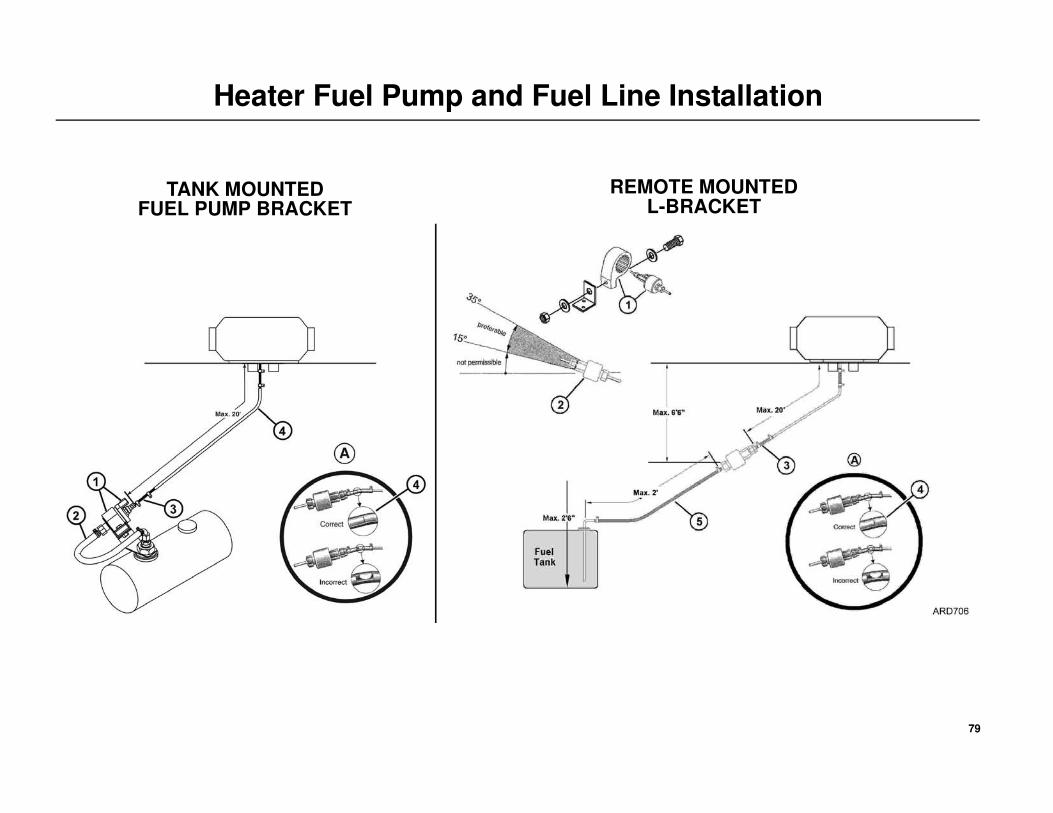
79
Heater Fuel Pump and Fuel Line Installation
TANK MOUNTED FUEL PUMP BRACKET
REMOTE MOUNTEDL-BRACKET

80
Heater Fuel Pump Connections
Heater Fuel Pump Connections
1. Route the heater fuel pump harness (installed earlier) to the heater’s
fuel pump and cut the wires to the correct length.
• Strip wire ends, slide on rubber sealing boots, attach pin terminals
securely with crimping tool.
• Insert pin terminals into connector body until they lock in place.
NOTE: The pump is not polarity sensitive. The wires can be installed
in either location of the connector body.
• Snap locking cover closed on connector body.
• DO NOT connect the fuel pump harness to the fuel pump at this
time. The fuel pump harness will be attached later after the fuel
pump has been primed.
CAUTION: To prevent the heater from starting unexpectedly, set
all electrical controls to the OFF position BEFORE connecting
wires to battery.
Special Tools Required
Wire Cutters
Terminal Crimping Tool

81
Heater Fuel Pump Connections

82
Installing the Battery Cables
Installation at the Tractor’s Batteries
1. FUSE HOLDER
• Mount fuse holder securely with (installer supplied) 1/4-20
hardware and within 12.0 inches (304.8 mm) of the tractor’s
batteries.
• DO NOT install the fuse at this time.
2. POSITIVE BATTERY CABLE
• Route the positive cable from the TriPace to the fuse holder, cut to
length and strip 1/2 to 3/4 in. (13 to 19 mm) of insulation from
cable end.
• Slide the supplied RED heat shrink tubing and terminal ring onto
the end of the cable. Attach the terminal ring firmly to the cable.
• Position heat shrink tubing to cover exposed wires on the terminal
ring and use a heat gun to shrink the tubing in place.
• Install the positive cable terminal lug onto the fuse holder stud and
hand tighten the nut.
3. SHORT POSITIVE BATTERY CABLE
NOTE: Do not attach both the positive and the negative cables to a single
battery. For best results, attach the positive cable to the first battery and
the negative cable to the last battery as shown.
• This cable has two different size battery lugs. Install cable lug with
small hole onto the other fuse holder stud and hand tighten the nut.
• Install the ring connector with the large hole onto the battery’s
POSITIVE (+) connection and tighten securely.
• Apply Superlube (PN 203-524) onto the battery’s connection.
4. NEGATIVE BATTERY CABLE
NOTE: Do not attach both the positive and the negative cables to a single
battery. For best results, attach the positive cable to the first battery and
the negative cable to the last battery as shown.
• Route the negative cable from the TriPace to the tractor’s negative
battery, cut to length and strip 1/2 to 3/4 in. (13 to 19 mm) of
insulation from cable end.
• Slide the supplied BLACK heat shrink tubing and terminal ring
onto the end of the cable. Attach the terminal ring firmly to end of
cable.
• Position heat shrink tubing to cover exposed wires on the terminal
ring and use a heat gun to shrink the tubing in place.
• Install the negative cable terminal lug onto the battery’s
NEGATIVE (-) connection and tighten securely.
• Apply Superlube (PN 203-524) onto the battery’s connection.
Installation at the TriPace Battery Tray
5. POSITIVE BATTERY CABLES
• Inside the TriPace battery box, route and connect each positive
battery cable to each corresponding positive battery post and
tighten securely.
• Apply Superlube (PN 203-524) onto the battery’s connections.
• Position the protective boots over the terminal lugs.
6. FUSE
• Remove the nuts from the fuse holder, place the fuse onto the studs,
and on top of the battery cables lugs and reinstall the nuts. Tighten
the nuts to 120 in-lb (13.5 N•m).
• Close the fuse holder cover securely.

83
Installing the Battery Cables
Tractor’s Batteries

84
Priming the Heater Fuel Pump
Priming the Heater Fuel System
The heater uses a pulse style fuel pump. You must use the heater priming
harness to operate the fuel pump to prime the system. Applying continuous
power to the pump will not work.
NOTE: Verify there is a sufficient amount of fuel in the fuel tank.
1. Attach the Heater Priming Harness connector to the heater fuel
pump.
2. Attach the alligator clips to the battery:
3. Turn the priming harness switch to the “ON” position.
4. The flasher unit will operate the fuel pump (ON/OFF/ON/OFF) to
prime the system.
5. Allow the system to operate for approximately 5 minutes to bleed air
from the fuel lines.
NOTE: Running the fuel pump longer then 5 minutes will cause the
heater to emit excessive white smoke when operated.
6. Check fuel lines and system for leaks.
7. Turn the priming harness switch to the “OFF” position. Disconnect the
positive and then the negative battery connections.
8. Disconnect the priming harness connector from the heater fuel pump.
9. Attach the heater fuel pump harness onto the heater fuel pump.
Special Tools Required
Heater Priming Harness (204-1144)
Wire Battery Connection
RED POSITIVE
BLACK NEGATIVE
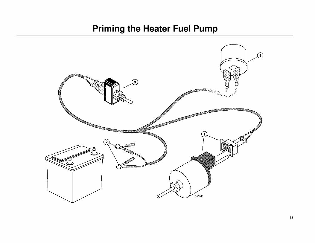
85
Priming the Heater Fuel Pump

86
A/C System Charging Procedures
Adding Refrigerant Charge
NOTE: The system should be charged with refrigerant only after
following “A/C System Evacuation and Leak Check Procedures” on
page 42.
IMPORTANT: Keep all the A/C fittings capped and sealed until the
installation of the refrigeration hoses. PVE refrigerant oil is extremely
hygroscopic and a system left open for more than 5 minutes may require
extensive evacuation time to remove moisture.
1. Connect the refrigerant bottle to the gauge manifold and place it on a
scale.
2. Open the refrigerant bottle valve for liquid and purge the charging line.
3. Keep the low pressure side valve of the gauge manifold closed. Open
the high pressure side valve.
4. Slowly add refrigerant until reaching 2 lbs. of R-134a.
NOTE: The system never uses more than 2 lbs. of refrigerant.
5. Close the refrigerant bottle valve and the high side valve of the gauge
manifold.
6. Remove the gauge manifold.
7. Reinstall the service valve caps.
8. Reinstall only the access cover over the evaporator coil.
Special Tools Required
R134a Refrigerant
Scale
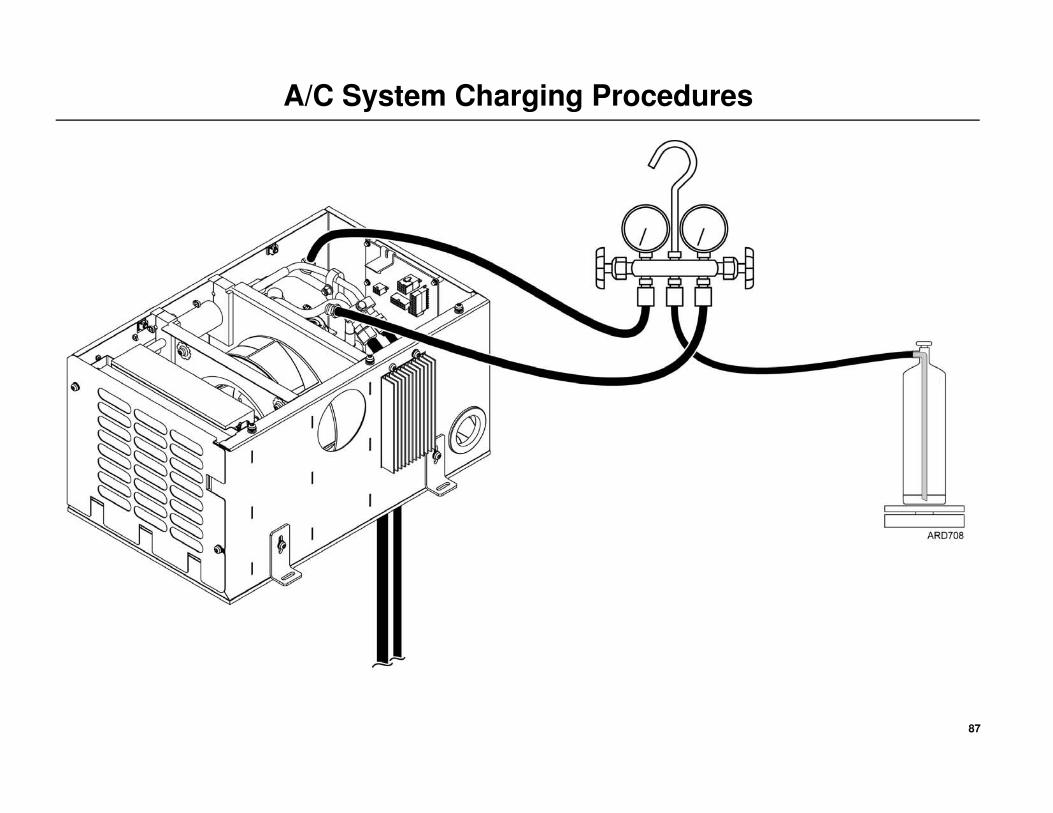
87
A/C System Charging Procedures

88
TriPace Operation Checkout Procedures
IMPORTANT! An Operation Checkout Procedure
must be performed.
Refer to TK-54678-19-MS
Once this procedure is completed,
continue to the system check list.

89
System Check List
BATTERY BOX - Mounting claws (or direct frame mounted
bolts) positioned correctly and torqued to specifications.
CONDENSER - Mounting bolts tightend securely and sealed
with silicone.
RECEIVER DRIER - Mounting bands tightend securely.
EVAPORATOR / CONTROL BOX - Mounting bolts tightend
securely and sealed with silicone.
EVAPORATOR DRAIN TUBES - Installed and access holes in
floor sealed with silicone.
REFRIGERATION HOSES - Routed and secured to allow for
movement and vibration.
REFRIGERATION FITTINGS - Tightend to proper torque
specifications.
ELECTRICAL - Electrical wiring and battery cables connected
tightely, properly routed and secured.
A/C SYSTEM - Properly charged and free of leaks.
HEATER INTAKE AND EXHAUST - Heater intake and
exhaust hoses routed safely and secured.
HEATER FUEL LINES - All fuel lines are routed safely and
secured.
HEATER FUEL LINE CONNECTIONS - All fuel line
connections are tight and leak free.
SAFETY GUARDS - All covers and grilles Installed securely.
AIR GAPS - Verified any unused holes in the sleeper floor are
completely sealed closed with caulking and the 3” access hole
inside the sleeper floor is completely caulked from both inside
and underneath.
SYSTEM OPERATION - The Operation Checkout Procedures were run, all system components operate correctely with no error codes.
TRACTOR INTERIOR - Thoroughly cleaned and vacuumed.
RELEASE TO CUSTOMER

Installation Manual
Providing equipment and services to manage controlled-temperature environments for food and other temperature-sensitive products, our Climate Control Technologies sector encompasses both transport and stationary refrigeration solutions. Our product brands include Thermo King®, a world leader in transport temperature control systems, and Hussmann®, a manufacturer of refrigeration and food merchandising equipment.
www.thermoking.com www.hussmann.com www.ingersollrand.com
©2008 Ingersoll-Rand Company Printed in U.S.A. on Recycled Paper
TriPac e ™ Auxiliary Heating
and Cooling Temperature Management System
TK 54468-19-IM (Rev. 2, 12/11)


