21
Fingerprint Access Control/Attendance Time Clock Installation Manual Rev: 1.0

7/17/2019 Installation Manual v1
http://slidepdf.com/reader/full/installation-manual-v1 1/20
Fingerprint Access Control/Attendance
Time Clock
Installation ManualRev: 1.0

7/17/2019 Installation Manual v1
http://slidepdf.com/reader/full/installation-manual-v1 2/20
Contents
I. BEFORE INSTALLATION ..................................................................... - 3 -
1.1 PRECAUTIONS OF INSTALLATION ....................................................... - 3 -
1.2 PANEL OVERVIEW ......................................................................... - 4 -
1.3 PACKAGING LIST ........................................................................... - 5 -
1.4 OTHER PARTS............................................................................... - 6 -
II. SYSTEM STRUCTURE ......................................................................... - 7 -
2.1 DIAGRAM OF SYSTEM INSTALLATION ................................................. - 7 -
2.2 DIAGRAM OF COMMUNICATION CONNECTION .................................... - 7 -
III. INSTALLATION .............................................................................. - 9 -
3.1 DETAILED INSTALLATION ................................................................. - 9 -
3.2 CONNECTING PERIPHERAL EQUIPMENT ............................................ - 10 -
3.2.1 Magnetic door detector ......................................................... - 11 -
3.2.2 Open button ........................................................................... - 11 -
3.2.3 Alarm ..................................................................................... - 11 -
3.2.4 Doorbell ................................................................................. - 11 -
3.2.5 Door lock ................................................................................ - 11 - 3.2.6 Ethernet connection............................................................... - 14 -
3.2.7 RS485 connection .................................................................. - 15 -
3.2.8 Full function connection of the Fingerprint Access
Control/Attendance T ime Clock ......................................................... - 16 -
IV. EXAMINATION AFTER INSTALLATION ............................................. - 17 -
V. ANTI-TAMPER SWITCH ................................................................... - 18 -
VI. TROUBLESHOOTING ................................................................... - 19 -

7/17/2019 Installation Manual v1
http://slidepdf.com/reader/full/installation-manual-v1 3/20
Fingerprint Access Control/Attendance Time Clock
- 3 - Before installation
I.
Before installation
1.1 Precautions of installation
Before installing, please read the installation precautions of the Fingerprint Access
Control/Attendance Time Clock carefully. Proper operation will improve the effect and
speed significantly. If you don’t read the following precautions before installing, it
may cause accident because of improper installation.
1. Before installing, please make sure that the power supply is cut off . It is
dangerous to operate if the power supply is connected and the device or even the
core parts will be damaged because of the contact of power cord.
2. The bare parts of all connection terminals shouldn’t exceed 5mm to prevent
accident contact and damage the device because the bare wire is too long. Youalso need to use connection cables of different colors.
3. To install the device at places with serious static electricity or in dry season,
please connect the ground wire first and then other cables to avoid damaging
the device because of large transient static electricity.
4. Connect all cables before connecting the power cord. If the device can’t work
normally, please cut off the supply and then check the device. Please note that any
operation when the power supply is connected may damage the device, and the
warranty doesn’t cover the damage caused by such operation.
5. The appropriate installation height of the device is 1.4~1.5m.
6. After installation, please take off the protective film on the fingerprint
collector to ensure best recognition effect.
7.
Test the open switch when there is person outdoor, because accident may occur
and you can’t go out normally.
8. 12V DC power supply is recommended for this device. 2A/12VDC electric lock

7/17/2019 Installation Manual v1
http://slidepdf.com/reader/full/installation-manual-v1 4/20
Fingerprint Access Control/Attendance Time Clock
- 4 - Before installation
is recommended. Please contact qualified technical personnel if the power supply
parameters of the lock exceed this range. If the power supply doesn’t reach this
requirement, it may can’t drive the electric lock and even damage the dev ice.
9. To connect the wires for the Fingerprint Access Control/Attendance Time Clock,
please follow the Installation Manual strictly. The warranty doesn’t cover the
damages of the core parts and the fingerprint collector caused by improper
connection.
10. If the distance between the power supply and the device is far, do not connect
with network cable or other cables. To select power cord, the voltage attenuation
because too long transmission distance should be considered.
11. To network in 485-mode, please use professional 485-cable and activate
RS232/485 converter and wire in general line structure. If the distance of RS485
communication exceeds 100m, please add terminal matching resistor at the start
terminal device and the end terminal device of the RS485 bus. The resistance is
about 120Ω.
12. For other matters, please refer to the Installation Manual and Hardware Manual of
the device.
1.2
Panel overview
1. LED indicator: the red indicator is constantly
on when the device is working normally. The
green indicator lights for three seconds if the
validation passes and won’t light if the validation
doesn’t pass.
2. Display: display time and characters, making
it convenient for the user to collect the operating
information of the Fingerprint Access
Control/Attendance Time Clock.
3. Keypad: press to input figures and operate
menus.

7/17/2019 Installation Manual v1
http://slidepdf.com/reader/full/installation-manual-v1 5/20
Fingerprint Access Control/Attendance Time Clock
- 5 - Before installation
4. Doorbell button: notify the people inside the
door that there is visitor.
5. Fingerprint collector: Record or compare
fingerprints.
6. Card reading position: Sensing area of ID
card.
7. RJ45 interface: connect network cable.
8.
Anti-tamper switch: the switch is pressed down when it is installed and it
alarms when released.
9. Power off button: press to turn off the device.
10. Connector: connect power supply, peripheral equipment, access controller,
networking communication, etc.
1.3
Packaging list
Unit Picture Quantity Purpose
Fingerprint Access
Control/Attendance
Time Clock
1
Installation template 1 To fix the installation
position, drill holes and
distribute wire before
installation
Screw 4 To fix the Fingerprint Access
Control/Attendance Time
Clock

7/17/2019 Installation Manual v1
http://slidepdf.com/reader/full/installation-manual-v1 6/20
Fingerprint Access Control/Attendance Time Clock
- 6 - Before installation
Manual 2 Installation Manual and User
Manual
1.4 Other parts
The following parts are mentioned in this Manual but aren’t included in the standard
configuration.
Unit Picture Unit Picture
Computer Door lock
Magnetic door
detector
Open switch
Alarm 485 converter
Access controller Network cable
Doorbell

7/17/2019 Installation Manual v1
http://slidepdf.com/reader/full/installation-manual-v1 7/20
Fingerprint Access Control/Attendance Time Clock
- 7 - System structure
II.
System structure
2.1 Diagram of system installation
2.2
Diagram of communication connection
1) The Fingerprint Access Control/Attendance Time Clock networks with the PC
through RS485:

7/17/2019 Installation Manual v1
http://slidepdf.com/reader/full/installation-manual-v1 8/20
Fingerprint Access Control/Attendance Time Clock
- 8 - System structure
2) The Fingerprint Access Control/Attendance Time Clock networks with the PC
through TCP/IP:
7/17/2019 Installation Manual v1
http://slidepdf.com/reader/full/installation-manual-v1 9/20
Fingerprint Access Control/Attendance Time Clock
- 9 - Installation
III.
Installation
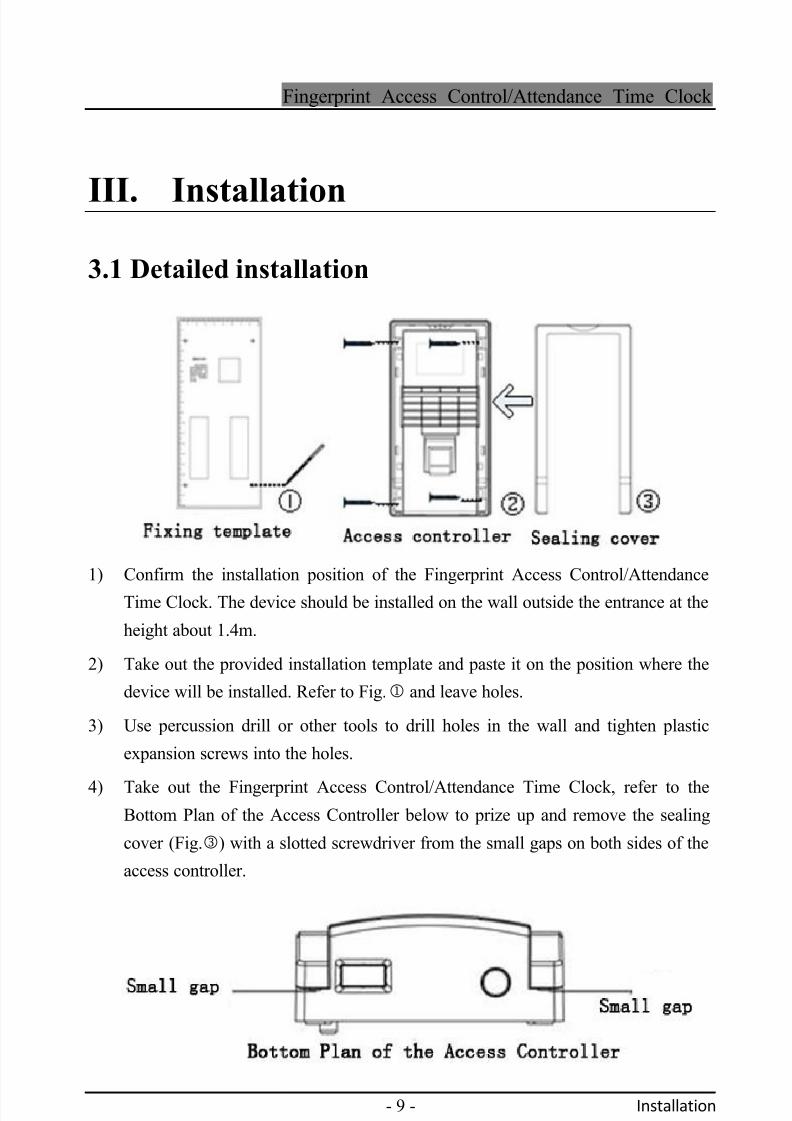
3.1 Detailed installation
1) Confirm the installation position of the Fingerprint Access Control/Attendance
Time Clock. The device should be installed on the wall outside the entrance at the
height about 1.4m.
2) Take out the provided installation template and paste it on the position where the
device will be installed. Refer to Fig. and leave holes.
3) Use percussion drill or other tools to drill holes in the wall and tighten plastic
expansion screws into the holes.
4)
Take out the Fingerprint Access Control/Attendance Time Clock, refer to the
Bottom Plan of the Access Controller below to prize up and remove the sealing
cover (Fig.) with a slotted screwdriver from the small gaps on both sides of the
access controller.

7/17/2019 Installation Manual v1
http://slidepdf.com/reader/full/installation-manual-v1 10/20
Fingerprint Access Control/Attendance Time Clock
- 10 - Installation
5) Refer to section 3.2 to connect the peripheral equipment. After connecting the
wires, please test the Fingerprint Access Control/Attendance Time Clock and
peripheral equipment.
6) Refer to Fig. and fix the Fingerprint Access Control/Attendance Time Clock
with provided screws.
7) Put on the sealing cover.
3.2 Connecting peripheral equipment
Before connecting, please make sure that the power supply has been cut off. It may
damage the device if the wires are connected in electrified state. Refer to the following
table to connect peripheral equipment.
Interface definition
(Left)
Interface definition
(right)
DC input (+12V) DC input (+12V)
Earth wire (GND) Earth wire (GND)
Power input of the lock
(COM)Signal input (CTL-IN)
Normal open output of
the lock (NO)WG DO input (D0-IN)
Normal closed output
of the lock (NC)WG D1 input (D1-IN)
Go out button input
(OPEN-KEY)
WG data 0 output
(WG-DATA0)Magnetic door
detector input (SEN)
WG data 1 output
(WG-DATA1)
Doorbell input
(BELL-IN)
Alarm 1 input
(ALM1-IN)
Doorbell output
(BELL-OUT)
Alarm 1 output
(ALM1-OUT)
Alarm 0 input
(ALMO-IN) 485A
Alarm 0 output
(ALMO-OUT)485B

7/17/2019 Installation Manual v1
http://slidepdf.com/reader/full/installation-manual-v1 11/20
Fingerprint Access Control/Attendance Time Clock
- 11 - Installation
3.2.1 Magnetic door detector
The magnetic door detector is used to detect the state of the door. This Fingerprint
Access Control/Attendance Time Clock can detect whether the door is opened illegally
through the detector. If the door is opened illegally, the device sends alarm signal. In
addition, if the door isn’t closed in specified time after opening, it also sends alarm
signal.
3.2.2 Open button
The Open button is the door switch device installed in the room. The door opens when
this button is closed. The Open button is fixed on the wall in the room at the height
about 1.4m from the floor. The Open button should be protected from electromagnetic
disturbance (e.g. the lighting switch and PC will cause electromagnetic disturbance).
3.2.3
Alarm
It is also called burglar alarm. It is a general designation of the electronic
products that alarm in sound, light or air pressure for accidents, dangers and
emergencies.
3.2.4 Doorbell
The doorbell terminal of this device is directly connected to the doorbell button on the
panel. You just need to connect the existing doorbell button cable to corresponding
terminal in the device.
3.2.5 Door lock
The installation of the door lock depends on its type and the influence caused bythe line resistance should be considered to select power cord for the lock. Make
sure the door lock is fixed and the connection is proper. For electric bolt and

7/17/2019 Installation Manual v1
http://slidepdf.com/reader/full/installation-manual-v1 12/20
Fingerprint Access Control/Attendance Time Clock
- 12 - Installation
magnetic lock, please make sure that the polarity is correct. If there is any cable
left, please cut off the bare end and wrap with insulation adhesive tape
separately.
Selecting door lock: for glass double-door (open either inside or outside), please
select electric bolt. For wood single door in offices (open only inside or outside),
please select magnetic lock . The magnetic lock is also called electromagnetic
lock and its stability is higher than electric bolt, but the electric bolt has higher
security. In communities, it’s better to use magnetic lock and electric bolt. The
electric bolt makes louder noise. Generally, most buildings use electric bolt. The
protection measures against rain are necessary for both magnetic lock and
electric bolt. Other electric locks are not recommended.
Connecting electric bolt: This Fingerprint Access Control/Attendance Time
Clock supports both normal open and normal closed door locks. The lock that
opens when electricity is connected and closes when electricity is cut off is called
normal closed lock and the control end is connected to NC terminal. The lock
that closes when electricity is connected and opens when electricity is cut off is
called normal open lock and the control end is connected to NO terminal.
The operating voltage of this Fingerprint Access Control/Attendance Time
Clock is DC 12V and the operating current is about 350mA.
The following are several wiring methods of locks (the first is recommended
for normal closed locks and the second is recommended for normal openlocks):

7/17/2019 Installation Manual v1
http://slidepdf.com/reader/full/installation-manual-v1 13/20
Fingerprint Access Control/Attendance Time Clock
- 13 - Installation
Connection diagram of electric lock
1) Normal closed
lock (share power
supply with
Fingerprint
Access Control /
Attendance Time
Clock)

7/17/2019 Installation Manual v1
http://slidepdf.com/reader/full/installation-manual-v1 14/20
Fingerprint Access Control/Attendance Time Clock
- 14 - Installation
2) Normal open
lock (share power
supply with
Fingerprint
Access Control /
Attendance Time
Clock)
3.2.6 Ethernet connection
1) The Fingerprint Access Control/Attendance Time Clock is connected to the PC
through crossover cable:

7/17/2019 Installation Manual v1
http://slidepdf.com/reader/full/installation-manual-v1 15/20
Fingerprint Access Control/Attendance Time Clock
- 15 - Installation
2) The Fingerprint Access Control/Attendance Time Clock is connected to the PC
through switch/hub with straight-through cable.
3.2.7 RS485 connection
To network with RS485, it is necessary to wire in general line network structure.
RS485 cable is made of a group of twisted pair cables and transmits signals through
the voltage difference between the two communication cables. The signals cause
differential mode interference between the two cables in the transmission process. To
eliminate differential mode interference, add terminal matching resistor between start
terminal device and end terminal device of RS485 bus. The resistance is 120Ω. (It is
not necessary to add generally)
The definition of terminal sideline:
RS485 converter Connection terminal of access controller
A+ 485A
B- 485B

7/17/2019 Installation Manual v1
http://slidepdf.com/reader/full/installation-manual-v1 16/20
Fingerprint Access Control/Attendance Time Clock
- 16 - Installation
3.2.8 Full function connection of the Fingerprint Access
Control/Attendance Time Clock
7/17/2019 Installation Manual v1
http://slidepdf.com/reader/full/installation-manual-v1 17/20
Fingerprint Access Control/Attendance Time Clock
- 17 - Examination after installation
IV.
Examination after installationAfter installing the system, please check the installation before connecting the
electricity. Connect the power supply if there is no problem, and then press the switch
to turn on the Fingerprint Access Control/Attendance Time Clock.
1) The red LED is on when the Fingerprint Access Control/Attendance Time Clock is
turned on.
2) Access [Menu] -> [Enroll] -> [User] -> [Finger] and register a fingerprint. Test the
access controller and door lock through fingerprint validation.
3) If there is no problem, delete the registered fingerprint.

7/17/2019 Installation Manual v1
http://slidepdf.com/reader/full/installation-manual-v1 18/20
Fingerprint Access Control/Attendance Time Clock
- 18 - Anti-tamper switch
V.
Anti-tamper switchThe anti-tamper switch is in the center right of the Fingerprint Access
Control/Attendance Time Clock (see Section 1.2 Panel overview). Press the
anti-tamper switch on the wall while installing the Fingerprint Access
Control/Attendance Time Clock. When the device is removed, the access controller
sends alarm signals. Refer to Section 3.2.8 Full function connection of the Fingerprint
Access Control/Attendance Time Clock for the connection of alarm.

7/17/2019 Installation Manual v1
http://slidepdf.com/reader/full/installation-manual-v1 19/20
Fingerprint Access Control/Attendance Time Clock
- 19 - Troubleshooting
VI.
TroubleshootingFault Reason and solution
The power LED (red)
isn’t lighted
Reason:
1) No power supply or voltage is low
Solution:
① Make sure that the power cord of the device and the earth
wire are in good condition;
② Test the voltage and make sure that it is 12VDC.
The Fingerprint
Access
Control/AttendanceTime Clock can’t
communicate with
the PC
Reason:
1) The connection cable has problem
Solution:
Check whether the RS485 cable and the TCP/IP cable are in
good condition.
The Fingerprint
Access
Control/Attendance
Time Clock repeats
prompting “Please
repress your finger!”
Reason:
1) After long term using, the fingerprint collector is dirty or
damaged and has scratch, and the fingerprint collector
considers it as fingerprint, but the validation isn’t passed after
comparison.
Solution:
① Use adhesive fabric to stick the dirt on the surface of the
fingerprint collector.
② Contact the supplier and request for warranty.
The time is incorrect Reason:

7/17/2019 Installation Manual v1
http://slidepdf.com/reader/full/installation-manual-v1 20/20
Fingerprint Access Control/Attendance Time Clock
- 20 - Troubleshooting
when the device is
restarted after power
failure
1) The clock battery is damaged.
2) The battery has no electricity.
Solution:
Change a new battery
The indicator of the
fingerprint collector
isn’t lighted
Reason:
1) The data cable of the fingerprint collector isn’t connected
properly.
2) The fingerprint collector is damaged.
Solution:
Contact the supplier and request for warranty.
No sound when press
the keys or
fingerprint
Reason:
1) The buzzer, speaker or circuitry has problem.
Solution:
Contact the supplier and change the buzzer or speaker.
Certain users often
can’t pass the
fingerprint validation
Reason:
The lines of the fingerprint aren’t clear
Solution:
When register fingerprint, please select the finger with high
quality fingerprint (few wrinkle, no skin rising, clear
fingerprint). Try to contact the fingerprint collector with larger
area. Test the fingerprint after registration. The device also
provides the following comparing modes: 1:1, password
registration and sensor card registration.


