Transmission Gear Kit with Clutch R35-GR6 INSTALLATION MANUAL Installation must be done by a professional. Read this manual prior to the installation. Always have access to this manual as well as a factory service manual. ※ Make sure the vehicle is applicable to this kit. REVISION OF MANUAL Rev. Number Date Details 3-3.01 2013/06 1 st Edition Published in June, 2013 by HKS Co., Ltd. (Unauthorized reproduction is strictly prohibited.) NAME OF PRODUCT Transmission Gear Kit with Clutch R35-GR6 PART NUMBER 27003-AN014 APPLICATION NISSAN GT-R R35 ENGINE VR38DETT YEAR 2007/11 - REMARKS The following items are required in order to install this product: ※ HKS DCT Fluid ・ DCTF-1 52002-AK001 (20L) ・ DCTF-2 52002-AK002 (20L) ※ Liquid Gasket: TB1217 or an equivalent ※ Silicone Grease: TB1855 or an equivalent
Transcript
Transmission Gear Kit with Clutch R35-GR6 INSTALLATION MANUAL
Installation must be done by a professional. Read this manual prior to the installation.
Always have access to this manual as well as a factory service manual.
※ Make sure the vehicle is applicable to this kit.
REVISION OF MANUAL
Rev. Number Date Details 3-3.01 2013/06 1st Edition
Published in June, 2013 by HKS Co., Ltd. (Unauthorized reproduction is strictly prohibited.)
NAME OF PRODUCT Transmission Gear Kit with Clutch R35-GR6 PART NUMBER 27003-AN014
APPLICATION NISSAN GT-R R35
ENGINE VR38DETT YEAR 2007/11 -
REMARKS The following items are required in order to install this product: ※ HKS DCT Fluid
※ Liquid Gasket: TB1217 or an equivalent ※ Silicone Grease: TB1855 or an equivalent
- 1 -
INDEX
NOTICE / SAFETY PRECAUTIONS········································································································1 PARTS LIST ············································································································································2 ATTENTION ··············································································································································5 1. PRIOR TO INSTALLATION···················································································································6 2. DISASSEMBLE OF FACTORY TRANSMISSION··············································································7 3. ASSEMBLY OF MAIN SHAFT ············································································································11 4. ASSEMBLY OF MAIN UNIT ················································································································22 5. ASSEMBLY OF CASE ·························································································································32 6. INSTALLATION OF CONTROL PARTS······························································································44 7. SUB-ASSEMBLY····································································································································50
NOTICE
This manual assumes that you have and know how to use the tools and equipment necessary to safely perform service operations on your vehicle. This manual assumes that you are familiar with typical automotive systems and basic service and repair procedures. Do not attempt to carry out the operations shown in this manual unless these assumptions are correct. Always have access to a factory service manual. To avoid injury, follow the safety precautions contained in the factory service manual. ATTENTION
● This manual indicates items you need to pay attention to in order to install this product safely and lists precautions to avoid any possible damage and/or accidents.
● This product is an automobile part. Do not use for any other purposes. ● HKS will not be responsible for any damage caused by incorrect installation and/or use, or use after modification
and/or dismantling of this product. ● This product was designed for installation on a specific factory vehicle. ● The specifications of this product are subject to change without notice. ● The instructions are subject to change without notice. Make sure to refer to the most recent instructions.
- 2 -
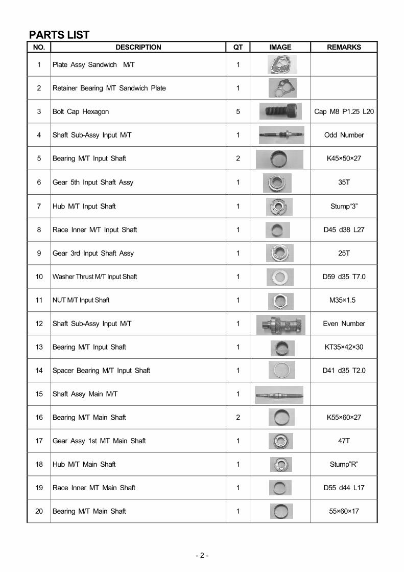
PARTS LIST NO. DESCRIPTION QT IMAGE REMARKS
1 Plate Assy Sandwich M/T 1
2 Retainer Bearing MT Sandwich Plate 1
3 Bolt Cap Hexagon 5
Cap M8 P1.25 L20
4 Shaft Sub-Assy Input M/T 1
Odd Number
5 Bearing M/T Input Shaft 2
K45×50×27
6 Gear 5th Input Shaft Assy 1
35T
7 Hub M/T Input Shaft 1
Stump“3”
8 Race Inner M/T Input Shaft 1
D45 d38 L27
9 Gear 3rd Input Shaft Assy 1
25T
10 Washer Thrust M/T Input Shaft 1
D59 d35 T7.0
11 NUT M/T Input Shaft 1
M35×1.5
12 Shaft Sub-Assy Input M/T 1
Even Number
13 Bearing M/T Input Shaft 1
KT35×42×30
14 Spacer Bearing M/T Input Shaft 1
D41 d35 T2.0
15 Shaft Assy Main M/T 1
16 Bearing M/T Main Shaft 2
K55×60×27
17 Gear Assy 1st MT Main Shaft 1
47T
18 Hub M/T Main Shaft 1
Stump”R”
19 Race Inner MT Main Shaft 1
D55 d44 L17
20 Bearing M/T Main Shaft 1
55×60×17
- 3 -
PARTS LIST NO. DESCRIPTION QT IMAGE REMARKS
21 Gear Assy Reverse MT Main Shaft 1
42T
22 Spacer Bearing MT Main Shaft 1
D66 d40 T6.4
23 Bearing M/T Main Shaft 1
NN3008
24 Gear Assy 4th MT Main Shaft 1
31T
25 Hub M/T Main Shaft 1
Stump “2”
26 Race Inner MT Main Shaft 1
D55 d44 L30
27 Bearing M/T Main Shaft 1
K55×60×30
28 Gear Assy 2nd MT Main Shaft 1
40T
29 Washer Thrust 2nd Gear MT Main Shaft 1
D91 d48 T10.6
30 Hub M/T Main Shaft 1
No Stumpmark
31 Race Inner MT Main Shaft 1
D46 d36 L40.5
32 Bearing M/T Main Shaft 1
K42×47×27
33 Gear Assy 6th MT Main Shaft 1
29T
34 Spacer Bearing M/T Main Shaft 1
D49 d30 T3.8~4.2
35 Race Inner MT Main Shaft 1
D37.5 d30 L21.3
36 Gear 5th MT Main Shaft 1
29T
37 Spacer M/T Main Shaft 1
D50 d40 L40
38 Gear 3rd MT Main Shaft 1
33T
39 Bearing M/T Main Shaft 1
NUP2206
40 NUT M/T Main Shaft 1
M27×1.5 LH
- 4 -
PARTS LIST NO. DESCRIPTION QT IMAGE REMARKS
41 Fork Assy Selector M/T 1
3rd-5th
42 Rod Selector M/T 1
D16 L290
43 Rod End M/T Selector Rod 1
3rd-5th
44 Pin Spiral 2
φ6 L25
45 Washer Thrust Reverse Idler MT 1
D38 d20 T3.0
46 Gear Reverse Idler 1
26T
47 Bearing M/T Reverse Idler 1
K 20×26×12
48 Bearing M/T Reverse Idler 1
K 20×26×17
49 Bearing M/T Main Shaft 1
NUP2206
50 Bearing M/T Main Shaft 1
6206
51 Fork Assy Selector M/T 1
Rev-1st
52 Fork Assy Selector M/T 1
2nd-4th
53 Fork Assy Selector M/T 1
6th
54 Cover Front M/T 1
55 Bearing Reduction Driven Gear 1
63/32
56 Spacer M/T Main Shaft 1
D40 d30 T1.7
57 Spacer M/T Main Shaft 1
D36 d27 T3.0
58 NUT M/T Main Shaft 1
M27×1.5
- 5 -
○ATTENTION
*Follow the factory service manual when working on the factory parts like the following: ・ Removing the factory transmission ・ Refilling fluid, etc.
*This product must be installed to a brand-new transmission manufactured after 2011(※1)
or a cleaned and inspected transmission.
If this product is assembled with a used transmission, it may cause unexpected damage due to the unbalanced transmission parts’ consumption. In Particular the transmission manufactured before 2010 may cause malfunctions of this product since the factory parts themselves may be defective. If a used transmission has to be used, make sure to inspect all parts carefully after disassembling and cleaning. If this product is installed to a brand-new transmission, malfunctions of the provided hydraulic systems (FCM/ACM) may be occurred. If any malfunction is noticed, check and clean the factory hydraulic module (FCM/ACM) and reinstall them.
※1 : It is recommended to use the factory transmission (P/N 320A0-KB50A) that HKS used for the installation test.
*Disassembly and installation process must be done in an immaculately clean room.
Prevent a foreign object and/or dust from entering into inside of the transmission to avoid malfunction.
*Disassembly and installation process must be done in horizontal and flat hard floor.
Transmission assembly weighs 140kgw. Work in horizontal and flat hard floor to prevent the transmission assembly from falling. If neglected, it may cause serious accident.
*Handle parts with care when disassembling.
Many factory parts will be reused. Make sure not to damage any parts when disassembling parts.
*Record how factory parts are installed (direction, position, order, etc.) before disassembling.
Before disassembling the factory parts, record the parts’ direction, position, order, etc. to put the disassembled factory parts back together correctly. Make sure to reassemble the factory parts to their original conditions.
*Pressing work must be carried out in a cautious manner.
Pressing work, especially disassembly, requires applying more than 100kN load in some cases. Wear protective equipment such as protective glasses, safety shoes, etc. to protect from parts or broken pieces that may be blown under pressing work. Maximum press-fit load for assembling under pressing work is designed to 10kN. If the press-fit load may exceed 20kN, check the position and/or conditions of press-fit part; then work over. NOTE If the press-fit cannot be done easily when disassembling, warm the press-fit part using a heat gun (a dryer for industrial use); then carry out press/pull work. Make sure not to heat the part above 160 degree Celsius.
*Shrinkage Fit
If an electric furnace is not available, use a heat gun (a dryer for industrial use) instead. When using a heat gun, make sure to heat the part evenly from all around it. Heating the part above 160 degree Celsius may cause strength degradation. To avoid the part from overheating, heat the part in a short time at first and extend heating period gradually. Make sure to cool the part to room temperature every time after heating the part.
- 6 -
1.PRIOR TO INSTALLATION
(1) The following tools are required in order to install this product in addition to common tools and equipment for automobile maintenance. (There are some special tools.)
・Hydraulic Press (w/ Load Gauge, Capacity 150kN+) ・Electric Furnace (w/Thermal Management, Capacity 100×100×40+) ・Dryer (Industrial Use, Capacity 3kW) ・ Puller (Various Types) ・ACM Piston Stopper ×2 (Dia.1-1-1) ・Collar A (O.D. 16, I.D. 12.3, Length 64, For Assembly Stand) (Dia.1-1-3) ・Collar B (O.D. 16, I.D. 12.3, Length 20, For Assembly Stand) (Dia.1-1-3) ・2 Types of Bolt M12 Pitch1.75 (Select bolts appropriate to use with
・ Transmission Stand (2 Type, One for engine assembly stand)
1-1-1
Bend φ1.5 wire as shown below:
55mm
40mm
1-1-2
A B C
1-1-3
AB
CD
- 7 -
2.DISASSEMBLY OF FACTORY TRANSMISSION
* Disassemble the transmission using the opposite of the assembly procedure. The following shows procedure different from the opposite of the assembly procedure. Refer to the assembly section.
(1) Remove the transmission from the vehicle in accordance
with the factory service manual. Completely drain the tank of DCT fluid.
(2) Remove the oil pan and oil strainer. (Dia.6-24-1, 6-23-1) (3) Insert the ACM piston stopper as shown in diagram 2-3-1. (4) Remove the actuator control module (ACM), oil filter case,
oil filter element, connecter, harness, and so on. Remove the O-ring (Large, Medium, Small) from the ACM. (Dia.6-10 – 20-1)
(5) Remove the front housing assembly. (Dia.6-7-2)
*Thrust washer may be remained in the front housing side. Check where the thrust washer is. (Dia.6-5-1)
(6) Install the clutch pack to the front housing in accordance with
the installation manual of the dual wet clutch kit. (7) Remove 3 pieces of the rotation sensor. (Dia.6-1-1, 6-3-1) (8) Remove the C-ring shown in the diagram; then remove the
front output gear using a puller. (Dia.2-8-1) (9) Remove the output shaft with the cover (P54 of the kit parts).
(Dia.5-52-1) (10) Remove the snap ring from the output shaft; then pull out the
bearing. Use the bearing and cover from the kit parts (Bearing P55, Cover P54). (Dia.5-52-1)
(11) Pull out the bearing shown in the diagram (P50 of the kit parts).
If the bearing cannot be pulled out easily, hit the tip of the shaft using a plastic hammer to make a gap between the bearing and case; then, put a puller on a bearing. (Dia.2-11-1)
(12) Remove the check balls of Rev-1st, 2nd-4th and 6th, shift rail, shift folk (P51, P52, and P53 of the kit parts).
(Dia.5-28 – 41-1) (13) Punch the roll pin and remove it. (P44 of the kit parts). (Dia.5-36-2) (14) Remove the snap ring from the input shaft (P12 of the kit parts). (Dia.5-37-1) (15) Remove the reverse idler fixture bolt, seal washer, check balls of 3rd-5th, and seal washer. (Dia.5-34-1,
5-35-1) (16) Remove the main case. (Dia.5-33-1) (17) Remove the gear train assembly from the rear case assembly. (Dia.5-29-2)
2-3-1
2-8-1
C-ring
2-11-1Bearing
Front Output Gear
ACM Piston Stopper
Holes
- 8 -
*The eye bolt cannot be installed to the factory Sandwich plate. Make sure to perform this procedure by more than 2 people to avoid injury.
(18) Remove the reverse idler shaft, park lock checker, oil baffle plate, oil feed pipe, and oil shield. (Dia.5-6 – 22-1) (19) Punch the roll pin and remove it. (P44 of the kit parts) Remove the shift rod (P42 of the kit parts) and shift folk
(P41 of the kit parts). (Dia.5-3-1) (20) Remove the main shaft and snap ring of odd-numbered input shafts’ ends (Screw type P40 and P11 of the kit
parts). (Dia.4-40-1) When disassembling HKS’ transmission, engage 1st and 3rd gear; then remove P40 and P11.
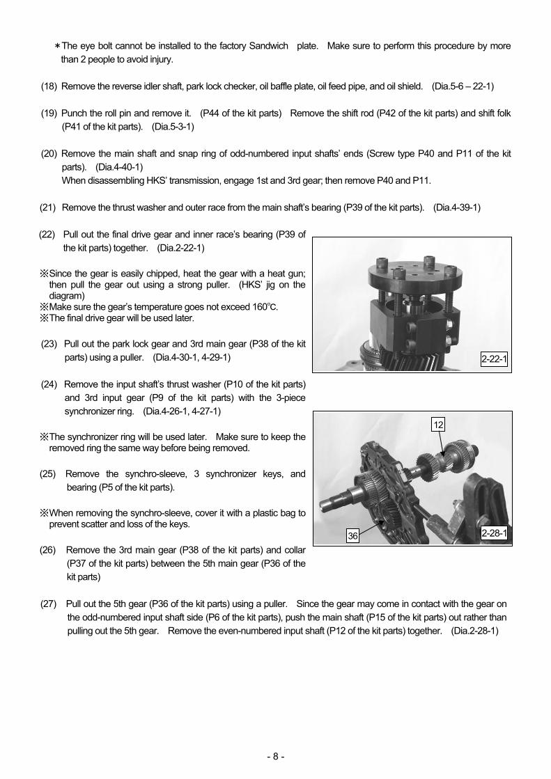
(21) Remove the thrust washer and outer race from the main shaft’s bearing (P39 of the kit parts). (Dia.4-39-1) (22) Pull out the final drive gear and inner race’s bearing (P39 of
the kit parts) together. (Dia.2-22-1) ※ Since the gear is easily chipped, heat the gear with a heat gun;
then pull the gear out using a strong puller. (HKS’ jig on the diagram)
※ Make sure the gear’s temperature goes not exceed 160℃. ※ The final drive gear will be used later. (23) Pull out the park lock gear and 3rd main gear (P38 of the kit
parts) using a puller. (Dia.4-30-1, 4-29-1) (24) Remove the input shaft’s thrust washer (P10 of the kit parts)
and 3rd input gear (P9 of the kit parts) with the 3-piece synchronizer ring. (Dia.4-26-1, 4-27-1)
※ The synchronizer ring will be used later. Make sure to keep the
removed ring the same way before being removed. (25) Remove the synchro-sleeve, 3 synchronizer keys, and
bearing (P5 of the kit parts). ※ When removing the synchro-sleeve, cover it with a plastic bag to
prevent scatter and loss of the keys. (26) Remove the 3rd main gear (P38 of the kit parts) and collar
(P37 of the kit parts) between the 5th main gear (P36 of the kit parts)
(27) Pull out the 5th gear (P36 of the kit parts) using a puller. Since the gear may come in contact with the gear on
the odd-numbered input shaft side (P6 of the kit parts), push the main shaft (P15 of the kit parts) out rather than pulling out the 5th gear. Remove the even-numbered input shaft (P12 of the kit parts) together. (Dia.2-28-1)
2-22-1
2-28-136
12
- 9 -
(28) Remove the retaining plate (P2 of the kit parts) from the sandwich plate (P1 of the kit parts). (Dia.4-4-1)
(29) Remove the snap ring as shown in diagram 2-30-1. (30) Remove the odd-numbered input shaft (P4 of the kit parts)
backward. (Dia.2-31-1) (31) Set the odd-numbered input shaft assembly to the press as
shown in diagram 2-32-1. Remove the 3rd gear inner race (P8 of the kit parts), 3rd-5th hub (P7 of the kit parts), 5th input gear (P6 of the kit parts), synchronizer ring, input bearing, 5th inner race, and thrust washer together. (Dia.2-32-1)
※The synchronizer ring will be used later. Make sure to keep the
removed ring the same way before being removed.
2-30-1Snap Ring
2-31-1
4
2-32-1
Input Bearing
- 10 -
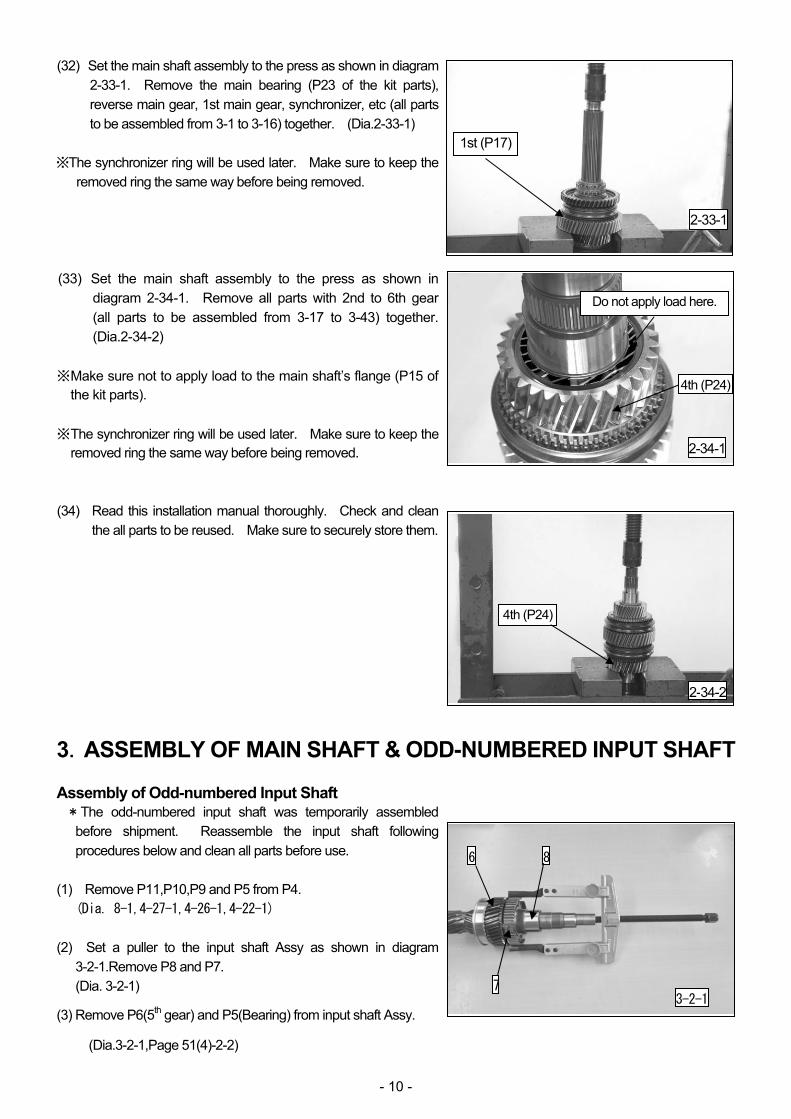
(32) Set the main shaft assembly to the press as shown in diagram 2-33-1. Remove the main bearing (P23 of the kit parts), reverse main gear, 1st main gear, synchronizer, etc (all parts to be assembled from 3-1 to 3-16) together. (Dia.2-33-1)
※The synchronizer ring will be used later. Make sure to keep the
removed ring the same way before being removed. (33) Set the main shaft assembly to the press as shown in
diagram 2-34-1. Remove all parts with 2nd to 6th gear (all parts to be assembled from 3-17 to 3-43) together. (Dia.2-34-2)
※ Make sure not to apply load to the main shaft’s flange (P15 of
the kit parts). ※ The synchronizer ring will be used later. Make sure to keep the
removed ring the same way before being removed. (34) Read this installation manual thoroughly. Check and clean
the all parts to be reused. Make sure to securely store them.
3.ASSEMBLY OF MAIN SHAFT & ODD-NUMBERED INPUT SHAFT Assembly of Odd-numbered Input Shaft *The odd-numbered input shaft was temporarily assembled
before shipment. Reassemble the input shaft following procedures below and clean all parts before use.
(1) Remove P11,P10,P9 and P5 from P4.
(Dia. 8-1,4-27-1,4-26-1,4-22-1) (2) Set a puller to the input shaft Assy as shown in diagram
3-2-1.Remove P8 and P7. (Dia. 3-2-1)
(3) Remove P6(5th gear) and P5(Bearing) from input shaft Assy.
(Dia.3-2-1,Page 51(4)-2-2)
2-33-1
1st (P17)
Do not apply load here.
2-34-2
4th (P24)
4th (P24)
2-34-1
3-2-1
8
7
6
- 11 -
Assembly of Main Shaft *The main shaft was temporarily assembled before shipment.
Disassemble and clean all parts before use. Disassemble the shaft referring to Section2. Disassembly of Factory Transmission.
(4) Install P16 to P15 as shown in diagram 3-4-1. *P16 is a 27mm-long bearing. P27 is a 30mm-long bearing.
Make sure to use a bearing of right length. (5) Install the factory inner synchro-ring to P17. (Dia.3-5-1) *Apply a drop of DCTF to the sliding part at intervals of 90 degree.
DCTF HKS DCTF-2
* Do not change the combination of the factory synchronizer. (6) Install the factory middle synchro-ring to P17 as shown in
diagram 3-6-1. *Apply a drop of DCTF to the sliding part at intervals of 90 degree.
DCTF HKS DCTF-2
* Do not change the combination of the factory synchronizer. (7) Install the factory outer synchro-ring as shown in diagram
3-7-1. *Apply a drop of DCTF to the sliding part at intervals of 90 degree.
DCTF HKS DCTF-2
* Do not change the combination of the factory synchronizer.
3-4-1
1516
Short Long
27mm
3-5-117
Inner Synchro-ring
3-6-117
Middle Synchro-ring
Align projection portions
3-7-117
Outer Synchro-ring
Align projection portions
- 12 -
(8) Install P17 to P15 as shown in diagram 3-8-1. *Apply a drop of DCTF to the thrust side of the P15 and P17 at
intervals of 180 degree.
DCTF HKS DCTF-2 (9) Install P18 to P15 as shown in diagram 3-9-1. *Apply a drop of DCTF to the thrust side of the P15 and P17 at
intervals of 180 degree.
DCTF HKS DCTF-2 *The side of P18 with “R” mark must be faced to the opposite side
of P17. *If P18 cannot be installed easily, press-fit it using a press. (10) Place Drift A on P19 as shown in diagram 3-10-1. Press-fit P19 to P15 using a press. (Dia.3-10-1, 3-10-2) *Make sure to press straight. *Press-fitting Load: Less than 20kN *Make sure if P17 rotates smoothly after press-fitting. (11) Install P20 to P19 as shown in diagram 3-11-1.
3-8-1
17
15
19
3-10-1 3-10-2
19 15
3-11-1
20 19
Drift A
18
“R” Mark
Align projection portions 3-9-1
15
- 13 -
(12) Install the factory synchro-sleeve to P18 as shown in diagram 3-12-1.
(13) Install the factory synchronizer keys (3 pcs.) to P18 as shown in
diagram 3-13-1. (14) Install the factory inner synchro-ring to P21 as shown in
diagram 3-14-1. *Apply a drop of DCTF to the sliding part at intervals of 90 degree.
DCTF HKS DCTF-2
* Do not change the combination of the factory synchronizer. (15) Install the factory middle synchro-ring to P21 as shown in
diagram 3-15-1. *Apply a drop of DCTF to the sliding part at intervals of 90 degree.
DCTF HKS DCTF-2
* Do not change the combination of the factory synchronizer.
3-12-1
18
Synchro-sleeve
3-13-1
Synchronizer Keys
3-14-121
Inner Synchro-ring
3-15-1
21
Middle Synchro-ring
Align projection portions
- 14 -
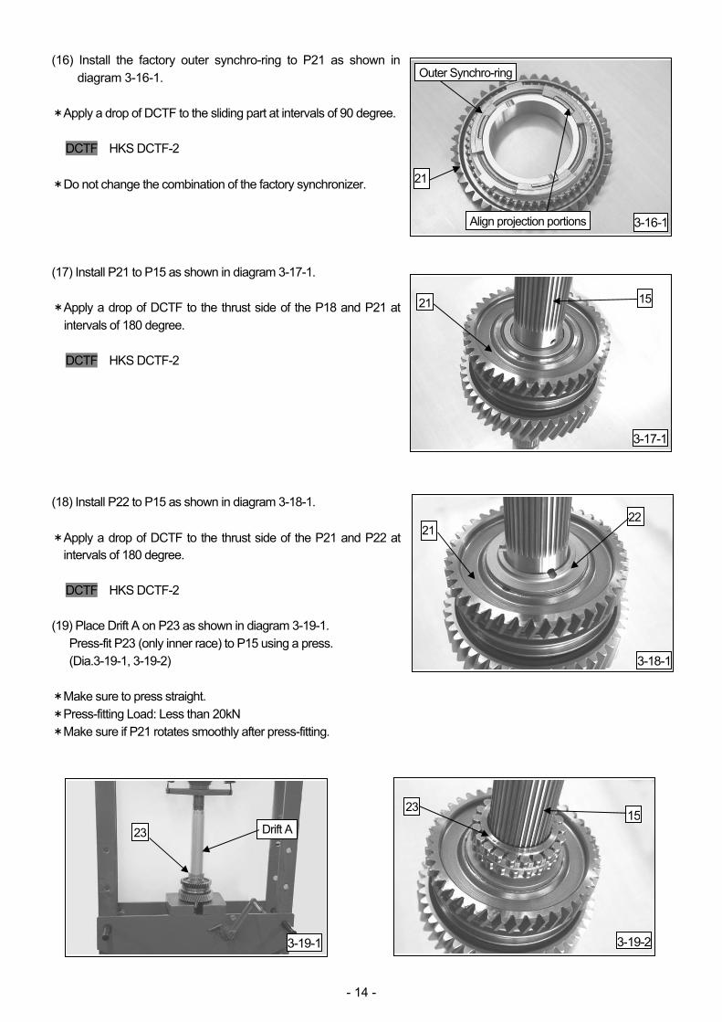
(16) Install the factory outer synchro-ring to P21 as shown in diagram 3-16-1.
*Apply a drop of DCTF to the sliding part at intervals of 90 degree.
DCTF HKS DCTF-2
* Do not change the combination of the factory synchronizer. (17) Install P21 to P15 as shown in diagram 3-17-1. *Apply a drop of DCTF to the thrust side of the P18 and P21 at
intervals of 180 degree.
DCTF HKS DCTF-2 (18) Install P22 to P15 as shown in diagram 3-18-1. * Apply a drop of DCTF to the thrust side of the P21 and P22 at
intervals of 180 degree. DCTF HKS DCTF-2
(19) Place Drift A on P23 as shown in diagram 3-19-1. Press-fit P23 (only inner race) to P15 using a press. (Dia.3-19-1, 3-19-2)
*Make sure to press straight. *Press-fitting Load: Less than 20kN *Make sure if P21 rotates smoothly after press-fitting.
3-16-1
Outer Synchro-ring
3-17-1
15
3-18-1
22
3-19-1
23
3-19-2
15Drift A
21
Align projection portions
21
21
23
- 15 -
(20) Install P16 to P15 as shown in diagram 3-20-1. *P16 is a 27mm-long bearing. P27 is a 30mm-long bearing.
Make sure to use a bearing of right length. (21) Install the factory inner synchro-ring to P24. (Dia.3-21-1) *Apply a drop of DCTF to the sliding part at intervals of 90 degree.
DCTF HKS DCTF-2
* Do not change the combination of the factory synchronizer. (22) Install the factory middle synchro-ring to P24 as shown in
diagram 3-22-1. *Apply a drop of DCTF to the sliding part at intervals of 90 degree.
DCTF HKS DCTF-2
*Do not change the combination of the factory synchronizer (23) Install the factory outer synchro-ring to P24 as shown in
diagram 3-23-1. *Apply a drop of DCTF to the sliding part at intervals of 90 degree.
DCTF HKS DCTF-2
* Do not change the combination of the factory synchronizer.
1516
3-20-1
3-21-124
3-22-1
24
3-23-1
Inner Synchro-ring
Middle Synchro-ring
Align projection portions
Outer Synchro-ringAlign projection portions
24
- 16 -
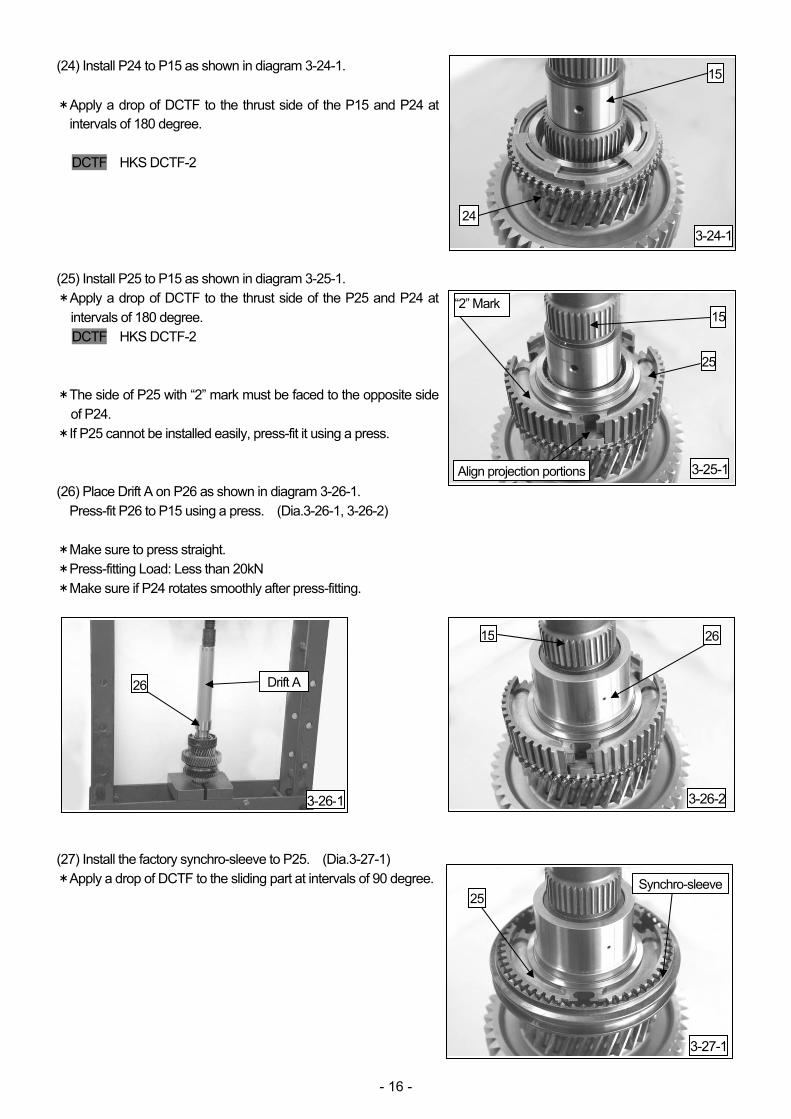
(24) Install P24 to P15 as shown in diagram 3-24-1. * Apply a drop of DCTF to the thrust side of the P15 and P24 at
intervals of 180 degree. DCTF HKS DCTF-2
(25) Install P25 to P15 as shown in diagram 3-25-1. *Apply a drop of DCTF to the thrust side of the P25 and P24 at
intervals of 180 degree. DCTF HKS DCTF-2
*The side of P25 with “2” mark must be faced to the opposite side
of P24. *If P25 cannot be installed easily, press-fit it using a press. (26) Place Drift A on P26 as shown in diagram 3-26-1. Press-fit P26 to P15 using a press. (Dia.3-26-1, 3-26-2)
*Make sure to press straight. *Press-fitting Load: Less than 20kN *Make sure if P24 rotates smoothly after press-fitting. (27) Install the factory synchro-sleeve to P25. (Dia.3-27-1) *Apply a drop of DCTF to the sliding part at intervals of 90 degree.
3-24-1
15
3-25-1
15
25
3-26-1
26
3-26-2
2615
3-27-1
Drift A
24
Align projection portions
“2” Mark
Synchro-sleeve25
- 17 -
(28) Install the factory synchronizer keys (3 pcs.) to P25 as shown in diagram 3-28-1.
(29) Install P27 to P26 as shown in diagram 3-29-1. *P16 is a 27mm-long bearing. P27 is a 30mm-long bearing.
Make sure to use a bearing of right length. (30) Install the factory inner synchro-ring to P28. (Dia.3-30-1) *Apply a drop of DCTF to the sliding part at intervals of 90 degree.
DCTF HKS DCTF-2
* Do not change the combination of the factory synchronizer. (31) Install the factory middle synchro-ring to P28 as shown in
diagram 3-31-1. *Apply a drop of DCTF to the sliding part at intervals of 90 degree.
DCTF HKS DCTF-2
* Do not change the combination of the factory synchronizer.
3-28-1
25
3-29-1
2627
3-30-1
3-31-1
28
Synchronizer Keys
Inner Synchro-ring
28
Middle Synchro-ring
Align projection portions
- 18 -
(32) Install the factory outer synchro-ring to P28 as shown in diagram 3-32-1.
*Apply a drop of DCTF to the sliding part at intervals of 90 degree.
DCTF HKS DCTF-2
* Do not change the combination of the factory synchronizer. (33) Install P28 to P15 as shown in diagram 3-33-1. * Apply a drop of DCTF to the thrust side of the P25 and P28 at
intervals of 180 degree. DCTF HKS DCTF-2
(34) Install P29 to P15 as shown in diagram 3-34-1. * Apply a drop of DCTF to the thrust side of the P29 and P28 at
intervals of 180 degree. DCTF HKS DCTF-2
(35) Install P29 and P30 to P15 aligning each axis as shown in
diagram 3-35-1. *If P30 cannot be installed easily, press-fit it using a press.
3-32-1
28
3-33-1
28
3-34-1
29
3-35-129
3015
Outer Synchro-ring
Align projection portions
15
15
- 19 -
(36) Place Drift B on P31 as shown in diagram 3-36-1. Press-fit P31 to P15 using a press. (Dia.3-36-1, 3-36-2) *Make sure to press straight. *Press-fitting Load: Less than 20kN *Make sure if P28 rotates smoothly after press-fitting. (37) Install the factory synchro-sleeve 6th to P30 as shown in
diagram 3-37-1. (38) Install the factory synchronizer keys (3 pcs.) to P30 as shown in
diagram 3-38-1.
(39) Install P32 to P31 as shown in diagram 3-39-1.
3-36-1
31
3-36-2
31 15
3-37-1
30
3-38-1
Flange on the lower side.
3-39-1
3231
Drift B
Synchro-sleeve 6th
30Synchronizer Keys
- 20 -
(40) Install the factory inner synchro-ring to P33. (Dia.3-40-1) *Apply a drop of DCTF to the sliding part at intervals of 90 degree.
DCTF HKS DCTF-2
* Do not change the combination of the factory synchronizer. (41) Install the factory middle synchro-ring to P33 as shown in
diagram 3-41-1. *Apply a drop of DCTF to the sliding part at intervals of 90 degree.
DCTF HKS DCTF-2
* Do not change the combination of the factory synchronizer. (42) Install the factory outer synchro-ring to P33 as shown in
diagram 3-42-1. *Apply a drop of DCTF to the sliding part at intervals of 90 degree.
DCTF HKS DCTF-2
* Do not change the combination of the factory synchronizer. (43) Install P33 to P15 as shown in diagram 3-43-1. * Apply a drop of DCTF to the thrust side of the P33 and P30 at
intervals of 180 degree. DCTF HKS DCTF-2
3-40-133
3-41-1
33
3-42-1
33
3-43-1
33
Inner Synchro-ring
Middle Synchro-ring
Align projection portions
Outer Synchro-ring
Align projection portions
15
- 21 -
(44) Place P35, P49 (only the outer race), and P50 as shown in diagram 3-44-1. Select P34 so the gap indicated by arrows in the diagram becomes 5.4mm to 5.5mm. P34 is pre-selected in the kit. (Dia.3-44-1, 3-44-2) * Check the shift folk’s condition of contact, and adjust the thickness of P34 at disassembly and inspection. *Pre-selected before shipment. (45) Install P34 selected in (44) to P15. (Dia.3-45-1) * Apply a drop of DCTF to the thrust side of the P33 and P34 at
intervals of 180 degree. DCTF HKS DCTF-2
(46) Place Drift B on P35 as shown in diagram 3-46-1. Press-fit
P35 to P15 using a press. (Dia.3-46-1, 3-46-2) *Make sure to press straight. *Press-fitting Load: Less than 20kN *Make sure if P28 rotates smoothly after press-fitting.
34 35 49
50
5.4~5.5mm
3-44-1
3-45-1
15
3-46-1
3-46-2
35
Notch
15
35 Drift B
3-44-2
Example of Measurement: Height Gauge
Float
34
- 22 -
4.ASSEMBLE OF MAIN UNIT
*P1 was temporally assembled before shipment. Reassemble before use.
* Clean all parts before use. (1) Install P1 to the assembly stand as shown in diagram 4-1-1. *Installation screw (M12×1.75) cannot hold the entire transmission.
Place only the gear train on the assembly stand. *The assembly stand installation screw is sealed by a decorative
screw and aluminum washer. Unseal the screw when installing the assembly stand.
(2) Install the outer race of P23 to P1 as shown in diagram 4-2-1. (3) Install P4 to P1 as shown in diagram 4-3-1. * Apply a drop of DCTF to the bearing indicated by an arrow in the
diagram 4-3-1 at intervals of 90 degree.
DCTF HKS DCTF-2 (4) Install P2 to P1 using 5 pieces of P3. Tightening Torque N・m 28±2.8
4-1-1
1
4-2-1
23 1
4-3-1
1 4 Apply DCTF
4-4-1
1
23
- 23 -
(5) Adjust the angle of the assembly stand so the tip of the P4 is slightly turned upward. (Dia.4-5-1)
*The adjustment is to prevent parts from falling down. After
adjustment, lock the stand’s angle. (6) Install P13 and P14 to P3 as shown in diagram 4-6-1. * Apply a drop of DCTF to the bearing indicated by an arrow in the
diagram 4-6-1 at intervals of 180 degree. DCTF HKS DCTF-2
* P13 and P14 are temporarily installed to the even-numbered
input shaft before shipment. (7) Install P12 to P4 as shown in diagram 4-7-1. (8) Apply a drop of DCTF to P23’s inner race of main shaft
assembly at intervals of 90 degree. (Dia.4-8-1)
DCTF HKS DCTF-2
4-5-1
4
4-6-1
4 13 14
Make a 10mm clearanceApply DCTF
4-7-112
4
4-8-1Main Shaft Assembly
23
Make a 10mm clearance
- 24 -
(9) Install the main shaft assembly to P1 as engaging to P12 as shown in diagram 4-9-1.
(10) Readjust the angle of the assembly stand horizontally. (11) Install P36 to P15 as shown in diagram 4-11-1.
The convex side of the P36 must be faced to P1. (Dia.4-11-1, 4-11-2)
* If P36 cannot be installed easily, knock P16 in by a plastic hammer using the drift A.
*Replace the main shaft assembly every time when it is come forward. (12) Install P5 to P4 as shown in diagram 4-12-1. (13) Install the factory inner synchro-ring to P6 as shown in diagram
4-13-1. *Apply a drop of DCTF to the sliding part at intervals of 90 degree.
DCTF HKS DCTF-2
* Do not change the combination of the factory synchronizer.
4-9-1
Main Shaft Assembly
12
1
4-11-1
36
15
4-11-2
361
4-12-1
45
4-13-16
Inner Synchro-ring
- 25 -
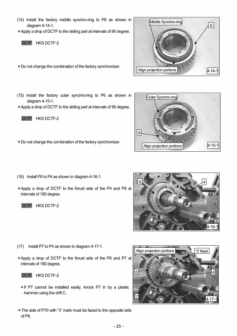
(14) Install the factory middle synchro-ring to P6 as shown in diagram 4-14-1.
*Apply a drop of DCTF to the sliding part at intervals of 90 degree. DCTF HKS DCTF-2
* Do not change the combination of the factory synchronizer. (15) Install the factory outer synchro-ring to P6 as shown in
diagram 4-15-1. *Apply a drop of DCTF to the sliding part at intervals of 90 degree.
DCTF HKS DCTF-2
* Do not change the combination of the factory synchronizer. (16) Install P6 to P4 as shown in diagram 4-16-1. * Apply a drop of DCTF to the thrust side of the P4 and P6 at
intervals of 180 degree. DCTF HKS DCTF-2
(17) Install P7 to P4 as shown in diagram 4-17-1. * Apply a drop of DCTF to the thrust side of the P6 and P7 at
intervals of 180 degree. DCTF HKS DCTF-2
* If P7 cannot be installed easily, knock P7 in by a plastic
hammer using the drift C. *The side of P70 with “3” mark must be faced to the opposite side
of P6.
4-14-1
Middle Synchro-ring
4-15-1
6
4-16-1
6 4
4-17-1
'3' Mark
4
6
Align projection portions
Outer Synchro-ring
Align projection portions
Align projection portions
6
7
- 26 -
(18) Install P37 to P15 as shown in diagram 4-18-1. (19) Heat P8 to 150 degree Celsius using an electric furnace; then
install P8 to P4 as shown in diagram 4-19-1. *Make sure the heating temperature does not exceed 160 degree
Celsius. NOTE P8 may be installed by hitting it using Drift C. (20) Install the factory synchro-sleeve to P7 as shown in diagram
4-20-1. (21) Install the factory synchronizer keys (3 pcs.) to P7 as shown in
diagram 4-21-1.
4-18-1
37
4-19-1
8
4-20-1
Synchro-sleeve
4-21-1
Synchronizer Keys
15
4
7
7
- 27 -
(22) Install P5 to P8 as shown in diagram 4-22-1. (23) Install the factory inner synchro-ring to P9 as shown in diagram
4-23-1. *Apply a drop of DCTF to the sliding part at intervals of 90 degree.
DCTF HKS DCTF-2
* Do not change the combination of the factory synchronizer. (24) Install the factory middle synchro-ring to P9 as shown in
diagram 4-24-1. *Apply a drop of DCTF to the sliding part at intervals of 90 degree.
DCTF HKS DCTF-2
* Do not change the combination of the factory synchronizer. (25) Install the factory outer synchro-ring to P9 as shown in
diagram 4-25-1. *Apply a drop of DCTF to the sliding part at intervals of 90 degree.
DCTF HKS DCTF-2
Do not change the combination of the factory synchronizer
4-22-1
9
Inner Synchro-ring
9
9
5
8
4-23-1
4-24-1
Middle Synchro-ring
Align projection portions
4-25-1
Outer Synchro-ring
Align projection portions
- 28 -
(26) Install P9 to P4 as shown in diagram4-26-1. * Apply a drop of DCTF to the thrust side of the P9 and P7 at
intervals of 180 degree. DCTF HKS DCTF-2
(27) Install P10 to P4 as shown in diagram 4-27-1. * Apply a drop of DCTF to the thrust side of the P6 and P7 at
intervals of 180 degree. DCTF HKS DCTF-2
(28) Temporarily install P11 to P4 as shown in diagram 4-28-1. Socket Size: 46mm Deep Socket (29) Install P38 to P15 as shown in diagram 4-29-1. * If P38 cannot be installed easily, knock P38 in by a plastic hammer using the
drift A. *Replace the main shaft assembly every time when it is come
forward. *The identifying groove on P38 must face backward.
4-26-1
4
4-27-1
10 4
4-28-1
11 4
4-29-1
38
15
9
ID Groove
- 29 -
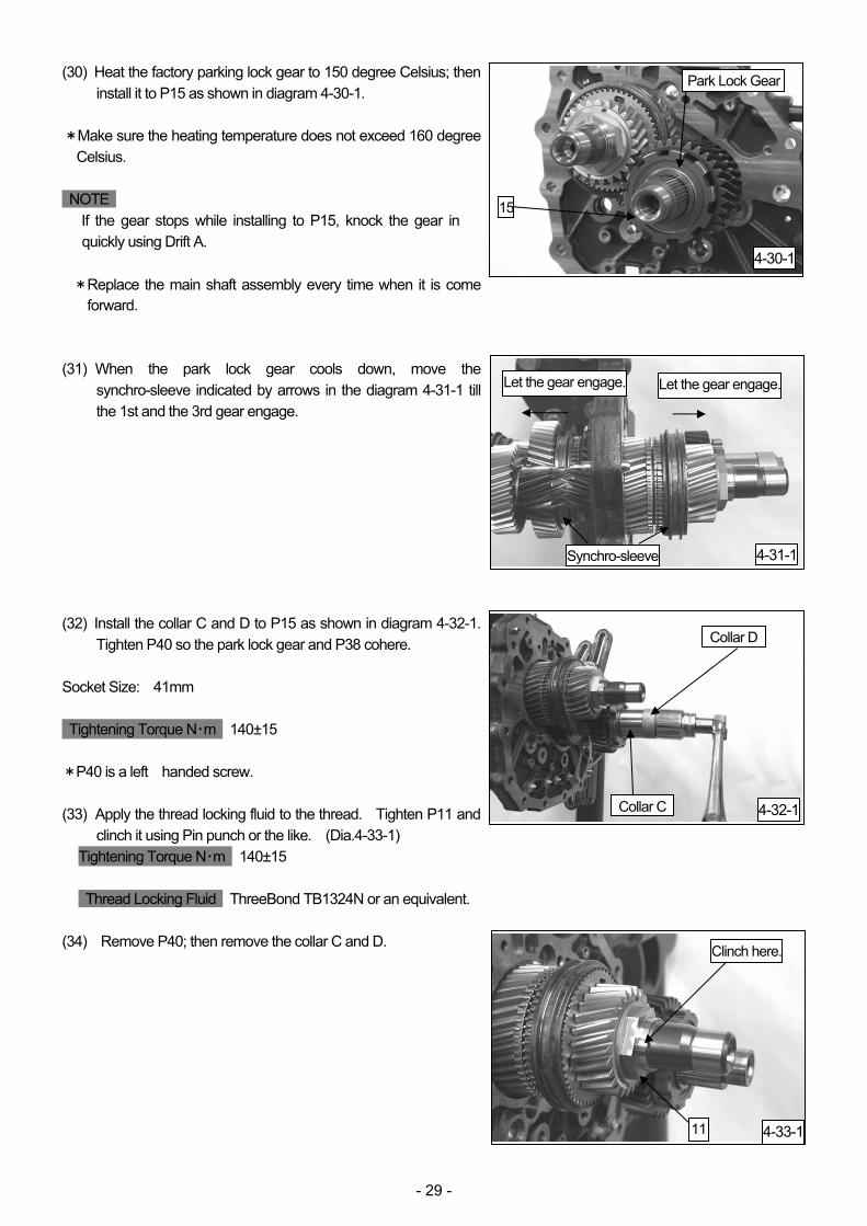
(30) Heat the factory parking lock gear to 150 degree Celsius; then install it to P15 as shown in diagram 4-30-1.
*Make sure the heating temperature does not exceed 160 degree
Celsius. NOTE
If the gear stops while installing to P15, knock the gear in quickly using Drift A.
* Replace the main shaft assembly every time when it is come forward.
(31) When the park lock gear cools down, move the
synchro-sleeve indicated by arrows in the diagram 4-31-1 till the 1st and the 3rd gear engage.
(32) Install the collar C and D to P15 as shown in diagram 4-32-1.
Tighten P40 so the park lock gear and P38 cohere. Socket Size: 41mm Tightening Torque N・m 140±15 *P40 is a left handed screw. (33) Apply the thread locking fluid to the thread. Tighten P11 and
clinch it using Pin punch or the like. (Dia.4-33-1) Tightening Torque N・m 140±15 Thread Locking Fluid ThreeBond TB1324N or an equivalent.
(34) Remove P40; then remove the collar C and D.
Park Lock Gear
15
4-31-1
Let the gear engage.
4-32-1Collar C
Collar D
4-33-111
Clinch here.
Synchro-sleeve
4-30-1
Let the gear engage.
- 30 -
(34) Heat the factory final drive gear to 150 degree Celsius as shown in diagrams below; then, install the gear to P15. (Dia.4-35-1, 4-35-2)
*Make sure the heating temperature does not exceed 160 degree Celsius. (35) When the final drive gear cools down, install the collar D to P15.
Tighten P40 so the final drive gear and park lock gear cohere. (Dia.4-36-1)
Tightening Torque N・m 200±20 (36) Remove P40 and collar. (37) Heat the inner race of P39 to 150 degree Celsius; then install
the inner race to P15 as shown in diagrams below. (Dia.4-38-1, 4-38-2)
*Make sure the heating temperature does not exceed 160 degree Celsius.
4-35-1 4-35-2
Installation Direction
Final Drive Gear
Final Drive Gear
15
4-36-1
4-38-139 (Inner Race)
Installation Direction
Final Drive Gear
Flange
4-38-2
Collar D
Park Lock Gear
15
39 (Inner Race)
- 31 -
(38) Install the outer race and thrust washer of P39 to P15 as
shown in diagram 4-39-1. (39) Tighten P40 by following procedures below: *Every time before tightening P40, make sure the thrust washer
of “39” fits in the convex of shorter side of “40”. Also,
make sure there is no gap in the area indicated in Diagram
4-40-2. (Dia.4-40-1, 4-40-2,4-40-3)
・1st Tightening Tightening Torque N・m 200±20 ・Loosen P40 completely and remove it. ・Clean the threaded portion. ・Apply thread locking fluid to the threaded portion. Thread Locking Fluid ThreeBond TB1324N or an equivalent ・2nd Tightening Tightening Torque N・m 140±14 ・Clinch the flange of P40 using a Pin punch. (40) Put the synchro-sleeve that was engaged in (31) back in place.
(Dia.4-31-1)
4-39-1
4-40-1
40
Clinch here.
39 (Outer Race)
39 (Thrust Washer)
39 (Thrust Washer)
40
No gap
40
39 (Thrust Washer)
Installation Direction
Shorter side
4-40-2
4-40-3
- 32 -
5.ASSEMBLY OF CASE *Clean all parts before use. (1) Modify the factory oil shield as shown in diagram 5-1-1. NOTE
Temporarily install the shield to P1 to check the shape of the shield during modification.
(2) Install P41 and P42 to the main unit as shown in diagram 5-2-1. (3) Apply DCTF to the tip of P44,Secure P41 to P42 using P44.
(Dia.5-3-1) *Before inserting P44, make sure to align holes of P41 and P42. (4) Move P41 as shown in diagram 5-4-1, and let the 3re gear to
engage.
5-1-1
Cut
5-2-1
41
42
5-3-141
42
44
5-4-1Move
41
- 33 -
(5) Check 9 points of 7 factory oil feed pipes’ O-rings as shown in diagram 5-5-1. Apply silicone grease to the O-rings.
Silicone Grease ThreeBond TB1855 (6) Install the oil feed pipe 1 to the main unit reusing the factory bolt
as shown in diagram 5-6-1. *Do not tighten the bolt completely. Bolt Size: M6 L15 with SP Washer (7) Install the oil feed pipe 2 reusing 2 factory bolts as shown in
diagram 5-7-1. *Do not tighten bolts completely. Bolt Size: M6 L15 with SP Washer (8) Install the modified oil shield and oil feed pipe 3 reusing 3
factory bolts as shown in diagram 5-8-1. *Do not tighten bolts completely. Bolt Size: M6 L15 with SP Washer
5-6-1Oil Feed Pipe 1
5-7-1
Oil Feed Pipe 2
5-8-1
5-5-1
1 2 3
4
5
6
7
Bolt (Temporarily Installed)
Bolts (Temporarily Installed)
Oil Feed Pipe 3 Bolts (Temporarily Installed)
Oil Shield
- 34 -
(9) Install the oil feed pipe 4 reusing the factory bolt as shown in diagram 5-9-1.
*Do not tighten bolts completely. Bolt Size: M6 L15 with SP Washer (10) Install the oil feed pipe 5 reusing the factory bolt as shown in
diagram 5-10-1. * Do not tighten bolts completely. Bolt Size: M6 L15 with SP Washer (11) Install the oil feed pipe 6 as shown in diagram 5-11-1. (12) Install the oil feed pipe 7 as shown in diagram 5-12-1.
5-9-1
5-10-1
5-11-1
Bend at 2 points
5-12-1
Long
Short
Bolt (Temporarily Installed)
Bolt (Temporarily Installed)
Oil Feed Pipe 5
Oil Feed Pipe 4
Oil Feed Pipe 6
Bend at 1 point
Oil Feed Pipe 7
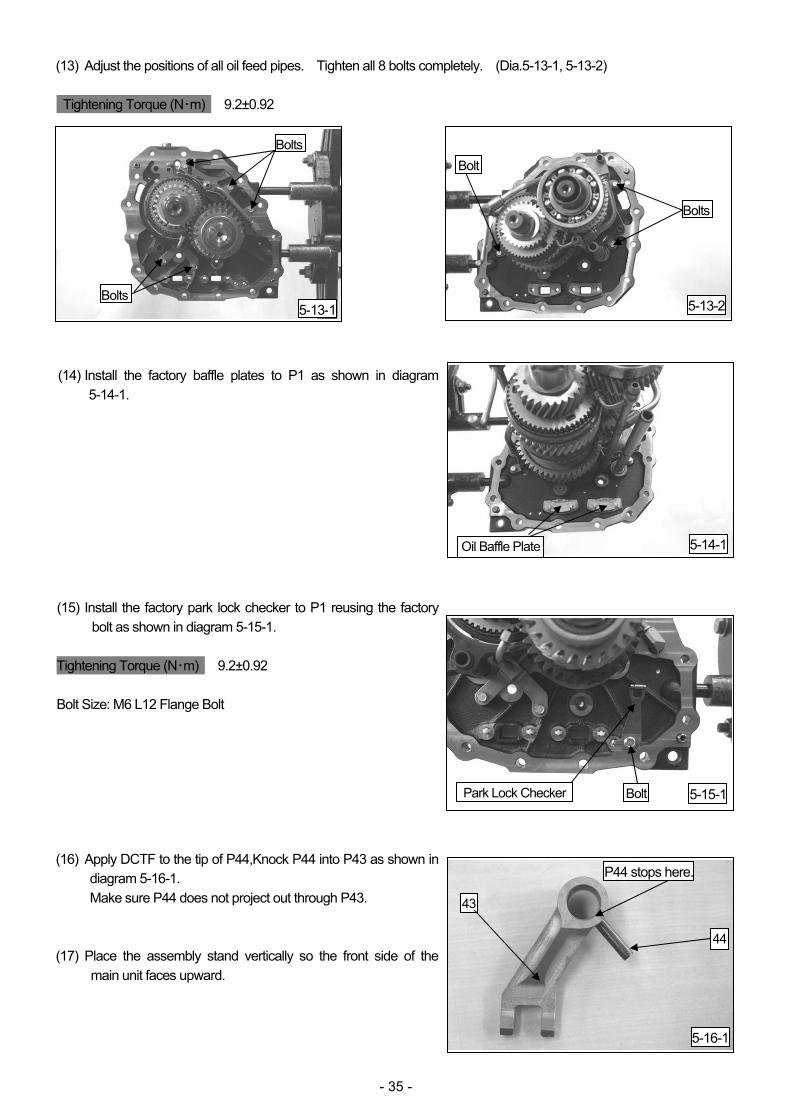
- 35 -
(13) Adjust the positions of all oil feed pipes. Tighten all 8 bolts completely. (Dia.5-13-1, 5-13-2) Tightening Torque (N・m) 9.2±0.92 (14) Install the factory baffle plates to P1 as shown in diagram
5-14-1. (15) Install the factory park lock checker to P1 reusing the factory
bolt as shown in diagram 5-15-1. Tightening Torque (N・m) 9.2±0.92 Bolt Size: M6 L12 Flange Bolt (16) Apply DCTF to the tip of P44,Knock P44 into P43 as shown in
diagram 5-16-1. Make sure P44 does not project out through P43.
(17) Place the assembly stand vertically so the front side of the
main unit faces upward.
Bolts
5-13-1 5-13-2
5-14-1Oil Baffle Plate
5-15-1Park Lock Checker
5-16-1
P44 stops here.
43
44
Bolts
Bolts
Bolt
Bolt
- 36 -
(18) Install P43 to P42 as shown in diagram 5-18-1. *Do not knock P44 in, yet. (19) Install P47 (12mm wide) and P48 (17mm wide) to the factory
reverse idler shaft as shown in diagram 5-19-1. (20) Install P46 to the factory reverse idler shaft as shown in
diagram 5-20-1. * Apply a drop of DCTF to the thrust side of the P46 at intervals of
180 degree. DCTF HKS DCTF-2
(21) Install P45 to P1 as shown in diagram 5-21-1.
5-18-1
43
42
5-19-1
47
48
Reverse Idler Shaft
5-20-1
46
5-21-1
45
1
Reverse Idler Shaft
- 37 -
(22) Install the reverse idler shaft as shown in diagram 5-22-1. * Apply a drop of DCTF to the thrust side of the P46 at intervals of
180 degree.
DCTF HKS DCTF-2 NOTE Align the screw hole of the reverse idler shaft with the hole position of the main case. (23) Make sure the parking lock system is installed properly to the
factory rear case assembly. (Dia.5-23-1) (24) Completely remove the gasket from the matching surface of
the rear case assembly. Clean inside. (25) Hold the rear case assembly vertically using a stand. Make
sure the flange side faces upward. A stand must be prepared separately.
NOTE A stand must be capable to hold the transmission assembly (approx. 140kgw). (26) Pour 10cc to 20cc of DCTF to the points indicated in the
diagram 5-26-1. DCTF HKS DCTF-2 (27) Remove oil from the matching surface of the rear case
assembly. Apply liquid gasket all over the surface as shown in diagram 5-26-1.
Liquid Gasket ThreeBond TB1217 (Gray) NOTE Liquid gasket’s thickness in the center of the flange and inside screw hole should be approximately 3mm in diameter. (28) Install 3 eye bolts to the service bolt (M10x1.5) of P1. Lift the
gear train assembly as shown in diagram 5-28-1.
5-22-1
46Screw Hole
5-23-1
Park Lock SystemRear Case Assembly
5-25-1
Rear Case Assembly
Liquid Gasket
Gear Train Assembly
5-26-1
5-28-1
Hole
Reverse Idler Shaft
Pour oil
Eye Bolts
- 38 -
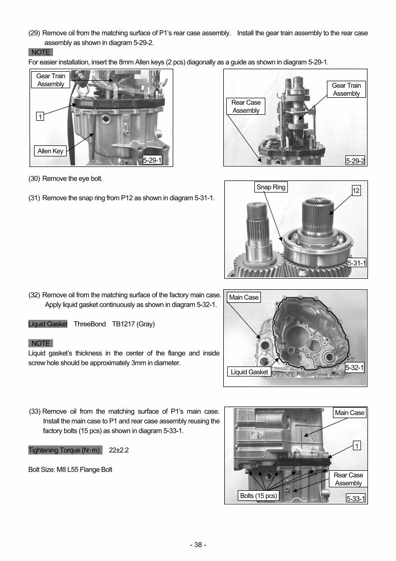
(29) Remove oil from the matching surface of P1’s rear case assembly. Install the gear train assembly to the rear case assembly as shown in diagram 5-29-2.
NOTE For easier installation, insert the 8mm Allen keys (2 pcs) diagonally as a guide as shown in diagram 5-29-1. (30) Remove the eye bolt. (31) Remove the snap ring from P12 as shown in diagram 5-31-1. (32) Remove oil from the matching surface of the factory main case.
Apply liquid gasket continuously as shown in diagram 5-32-1. Liquid Gasket ThreeBond TB1217 (Gray) NOTE Liquid gasket’s thickness in the center of the flange and inside screw hole should be approximately 3mm in diameter. (33) Remove oil from the matching surface of P1’s main case.
Install the main case to P1 and rear case assembly reusing the factory bolts (15 pcs) as shown in diagram 5-33-1.
(34) Install the reverse idler fixture bolt to the main case using the factory seal washer as shown in diagram 5-34-1.
Tightening Torque (N・m) 26.4±2.6 Seal Washer: O.D. 26.5, I.D. 12.3 (35) Install the 3rd-5th check ball to the rear case assembly using
the factory seal washer as shown in diagram 5-35-1. Seal Washer: O.D. 26.5, I.D. 20.4 Tightening Torque (N・m) 24.0±2.4 (36) Align the hole position of P43 and P42, and knock P44
completely in to secure P43 and P42 as shown in diagram 5-36-2.
NOTE Use the 5mm Allen key as a guide for easier hole position adjustment. (Dia.5-36-1)
(37) Secure P12 to the main case using the snap ring removed in
(31). (Dia.5-37-1)
Reverse Idler Fixture BoltSeal Washer
5-34-1
5-35-1Seal Washer
3rd-5th Chech Ball Rear Case Assembly
5-36-1
42
43
Allen Key
5-36-2
42
43
44
5-37-1Snap Ring
12Main Case
44
- 40 -
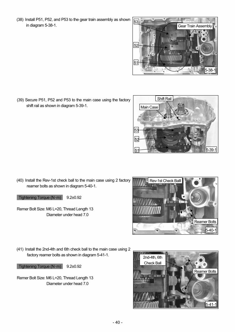
(38) Install P51, P52, and P53 to the gear train assembly as shown in diagram 5-38-1.
(39) Secure P51, P52 and P53 to the main case using the factory
shift rail as shown in diagram 5-39-1. (40) Install the Rev-1st check ball to the main case using 2 factory
reamer bolts as shown in diagram 5-40-1. Tightening Torque (N・m) 9.2±0.92 Remer Bolt Size: M6 L=20, Thread Length 13
Diameter under head 7.0 (41) Install the 2nd-4th and 6th check ball to the main case using 2
factory reamer bolts as shown in diagram 5-41-1. Tightening Torque (N・m) 9.2±0.92 Remer Bolt Size: M6 L=20, Thread Length 13
Diameter under head 7.0
5-38-1
53Gear Train Assembly
5-39-1
Shift Rail
Main Case
51
52
53
5-40-1
Reamer Bolts
Rev-1st Check Balll
5-41-1
2nd-4th, 6th Check Ball
52
51
Reamer Bolts
- 41 -
(42) Install the outer race of P49 to the main case as shown in diagram 5-42-1.
(43) Apply a drop of DCTF to the bearing parts of P49 and P12 at
intervals of 90 degree. (Dia.5-42-1)
DCTF HKS DCTF-2
(44) Heat P50 to 150 degree Celsius using an electric furnace; then install it to P15 as shown in diagram 5-44-1.
*Make sure the heating temperature does not exceed 160 degree
Celsius. (45) When P50 cools down, apply a drop of DCTF to P50 at
intervals of 90 degree. (Dia.5-44-1) DCTF HKS DCTF-2 (46) Install P56 (O.D. 40, I.D. 30, and Thickness 1.7) to P15 as
27.0, and thickness3.0) to P15 as shown in diagram 5-47-1.
5-42-149
Main Case
5-44-150
5-46-156
15
5-47-1
Collar D
15
Apply DCTF
15 Apply DCTF
57
- 42 -
(48) Operate the park lock lever to lock the park gear. (Dia.5-48-1) (49) Install P58 to P15. Tighten P58 so P50 and P15 cohere.
(Dia.5-49-1) Socket Size: 41mm Tightening Torque N・m 140±15 (50) Remove P58, P57, and collar D. (51) Insert P54 between the factory output shaft; then, press-fit P55
as shown in diagram 5-51-11 and 5-51-2. *Do not apply load to the outer race of P55. *Make sure to press straight. *Press-fitting Load: Less than 20kN (52) Secure P55 to the output shaft reusing the factory snap ring as
shown in diagram 5-52-1.
5-51-1
54
5536mm Socket Dowel
5-51-2
Output Shaft
5455
5-52-155
Snap Ring
5-48-1Park Lock Lever
Lock
5-49-1
5815
Release
Output Shaft
Output Shaft
- 43 -
(53) Install P54 to the main case reusing 12 factory bolts as shown in diagram 5-53-1.
Bolt Size: M8 L25, Flange Bolt Tightening Torque (N・m) 22±2.2 (54) Make sure P56 is installed as shown in diagram 5-53-1.
(55) Heat the front output gear 150 degree Celsius using an electric furnace; then install it to P15 as shown in diagram 5-55-1.
*Make sure the heating temperature does not exceed 160 degree
Celsius. (56) When the front output gear cools down, Install P57 (O.D. 36,
I.D. 27, and Thickness 3.0) to P15 as shown in diagram 5-56-1.
(57) Install P58 to P15 by following the procedure below: ・1st Tightening Tightening Torque N・m 140±20 ・Loosen P58 completely and remove it. ・Clean the threaded portion. ・Apply thread locking fluid to the threaded portion. Thread Locking Fluid ThreeBond TB1324N or an equivalent ・2nd Tightening Tightening Torque N・m 140±14 ・Clinch the flange of P58 using a Pin punch. (Dia.5-57-1) (58) Release the park lock. (Dia.5-48-1)
5-53-1
54
Main CaseBolt
56
5-55-1
15
5-57-1
58
Front Output Gear
5-56-1
57 15
15 Clinch here.
- 44 -
6. INSTALLATION OF CONTROL PARTS
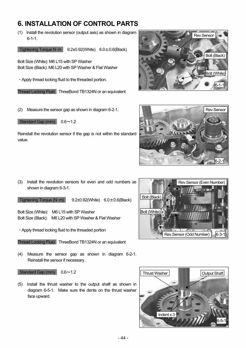
(1) Install the revolution sensor (output axis) as shown in diagram 6-1-1.
Tightening Torque N・m 9.2±0.92(White) 6.0±0.6(Black) Bolt Size (White): M6 L15 with SP Washer Bolt Size (Black): M6 L20 with SP Washer & Flat Washer ・Apply thread locking fluid to the threaded portion. Thread Locking Fluid ThreeBond TB1324N or an equivalent (2) Measure the sensor gap as shown in diagram 6-2-1. Standard Gap (mm) 0.6~1.2 Reinstall the revolution sensor if the gap is not within the standard value. (3) Install the revolution sensors for even and odd numbers as
shown in diagram 6-3-1. Tightening Torque (N・m) 9.2±0.92(White) 6.0±0.6(Black) Bolt Size (White): M6 L15 with SP Washer Bolt Size (Black): M6 L20 with SP Washer & Flat Washer ・Apply thread locking fluid to the threaded portion Thread Locking Fluid ThreeBond TB1324N or an equivalent (4) Measure the sensor gap as shown in diagram 6-2-1.
Reinstall the sensor if necessary. Standard Gap (mm) 0.6~1.2 (5) Install the thrust washer to the output shaft as shown in
diagram 6-5-1. Make sure the dents on the thrust washer face upward.
6-1-1
Rev.Sensor
Bolt (Black)
Bolt (White)
6-2-1
6-3-1
Rev.Sensor (Even Number)
6-5-1
Thrust Washer
Rev.Sensor
Bolt (Black)
Bolt (White)
Rev.Sensor (Odd Number)
Output Shaft
Indent x 3
- 45 -
(6) Remove oil from the matching surface of the main case.
Apply liquid gasket all over the surface as shown in diagram 6-6-1.
Liquid Gasket ThreeBond TB1217 (Gray) NOTE Liquid gasket’s thickness in the center of the flange and inside screw hole should be approximately 3mm in diameter. (7) Remove oil from the matching surface of the front housing HKS dual wet clutch is installed. Install the front
housing assembly to the main case using 20 factory bolts as shown in diagram 6-7-1 and 6-7-2. Make sure the connector is positioned as shown in diagram 6-7-1.
Tightening Torque (N・m) 22±2.2 Bolt Size: M8 L30 Flange Bolt (8) Apply silicone grease to the O-rings of black and green
connectors. Install the connectors to the main case as shown in diagram 6-8-1.
Silicone Grease ThreeBond TB1855 (9) Secure the connectors to the main case using the factory
clips as shown in diagram 6-9-1.
6-6-1
6-7-1
Connector
6-7-2
Front Housing Assembly
6-8-1
Align Notch
6-9-1
Clips
Bolt
Connector (Black)
Connector (Green)
Connector
Main Case
- 46 -
(10) Apply silicone grease to the factory O-ring S, M, and L.
Install the O-rings to the main case as shown in diagram 6-10-1.
(11) Install the actuator and control module (ACM) using the
Secure the connector using the factory bolt. (Dia. 6-12-1) Tightening Torque (N・m) 9.2±0.9 Bolt Size: M6 L15 with SP Washer (13) Connect the even-number and odd-number connectors.
Secure the connectors using the factory bolt. (Dia.6-13-1) Tightening Torque (N・m) 9.2±0.9 Bolt Size: M6 L15 with SP Washer
6-10-1
O-ring(S)
6-11-1
ACMBolts
6-12-1
Connector
6-13-1
O-ring(M)
O-ring(L)
Bolt
Connectors
Bolt
- 47 -
(14) Apply silicone grease to the O-ring of the factory filter
element. Install the filter element to the main case as shown in diagram 6-14-1.
Silicone Grease ThreeBond TB1855 (15) Apply silicone grease to the O-ring and threaded portion of
the factory filter case. Install them to the main case as shown in the diagram 6-15-1.
Silicone Grease ThreeBond TB1855 Tightening Torque (N・m) 30±3.0 Socket Size: 36mm (16) Connect the factory harness to 2 connectors as shown in
diagram 6-16-1. Secure the connectors using the factory bolt.
Tightening Torque (N・m) 9.2±0.92 Bolt Size: M6 L15 with SP Washer (17) Secure the ACM harness using the factory bolt as shown in
diagram 6-17-1. Bolt Size: M6 L15 with SP Washer
6-14-1
Filter Element
6-15-1
6-16-1
Harness
6-17-1
Filter Case
Bolt
Connectors
Bolt
ACM Harness
- 48 -
(18) Secure the temperature sensor as shown in diagram 6-18-1. (19) Connect the ACM harness to the green connector as shown
in diagram 6-19-1. (20) Remove the fixture pins from the ACM. (Dia.6-20-1) (21) Apply silicone grease to the packing of the oil pump inlet
as shown in diagram 6-21-1. Silicone Grease ThreeBond TB1855
6-18-1
Temperature Sensor
6-19-1
6-20-1
Packing
6-21-1
Oil Pump Inlet
ACM Harness
Connector
Fixture Pins
- 49 -
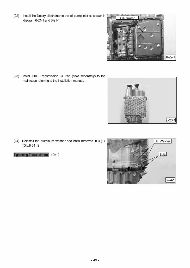
(22) Install the factory oil strainer to the oil pump inlet as shown in diagram 6-21-1 and 6-21-1.
(23) Install HKS Transmission Oil Pan (Sold separately) to the
main case referring to the installation manual. (24) Reinstall the aluminum washer and bolts removed in 4-(1).
(Dia.6-24-1) Tightening Torque (N・m) 40±12
6-22-1
Oil Strainer
6-23-1
6-24-1
AL Washer
Bolts
- 50 -
7.SUB-ASSEMBLY(Supplementary Information) □1 Assembly of Sandwich Plate *Pre-assembled before shipment.
(1) Press-fit “2” x 2 to “1” as shown in diagram (1)-1-1 and (1)-1-2. *Press-fitting Load: Less than 20kN *Make sure to press straight. (2) Press-fit “3” x 2 to “1” as shown in diagram (1)-2-1 and (1)-2-2. *Press-fitting Load: Less than 20kN *Make sure to press straight. (3) Install “4” to “1” through “5” as shown in diagram (1)-3-1. Tightening Torque (N・m) 40±12
(1)-1-1
6~9mm
1
2
(1)-1-2
2
2
1
(1)-2-1 (1)-2-2
3
1
3
1
(1)-3-15 4
Make sure (3)s do not come out.
- 51 -
□4 Assembly of Odd-number Axis Input Shaft
*Assembly process must be done in an immaculately clean room. *Pre-assembled before shipment. (1) Measure the width of “5” and “7”. Select “6” so the total width becomes 55±0.065. *”6” is pre-selected before shipment. * Adjust the thickness of “6” when checking the shift folk’s contact
condition at inspection after disassembly. (2) Press-fit “5” to “1” using Drift A as shown in diagram (4)-2-1
and (4)-2-2. *Make sure to press straight. *Make sure not to press the outer race of “5”. *Press-fitting Load: Less than 20kN *Make sure “5” rotates smoothly after press-fitting. (3) Install the selected “6” to “1”. (Dia.(4)-3-1) (4) Press-fit “7” to “1” using Drift C as shown in diagram (4)-4-1
and (4)-4-2. *Make sure to press straight. *Press-fitting Load: Less than 20kN
(4)-4-1 (4)-4-2
7
1
7
(4)-2-1
(4)-2-2
Drift A
5
1
1 5
Snap Ring
(4)-3-1
1
6
Drift C
- 52 -
(5) Install 2 pieces of “2”, “3”, and “4”. (Dia.(4)-5-1) Make sure to install “3” as shown in diagram (4)-5-2. (6) Apply Loctite 638 to the spacer. Press-fit the spacer to “1”. *Press-fitting Load: Less than 20kN ○ P4 is the finished sub-assembly. □12 Assembly of Even-number Axis Input Shaft
*Pre-assembled before shipment. (1) Install “2” to “1” as shown in diagram (12)-1-1.
If “2” cannot be installed easily, press-fit it to “1” using a press. (Dia.(12)-1-2) *The projection of “2” faces upward in diagram (12)-1-1. (2) Press-fit “3 to “1” as shown in diagram (12)-2-1. *The snap ring of “3” must be placed upper side as shown in diagram (12)-2-1) *Make sure to press straight. *Press-fitting Load: Less than 20kN *Make sure “3” rotates smoothly after press-fitting.
(4)-5-1
(12)-1-1 (12)-1-2
Projection Side
Flat Side
(12)-2-1
Snap Ring
2 3 4
2
1
3
(4)-5-2
Dent
To ②
- 53 -
(3) Install “4” (8.0mm thick) to “1”. (Dia.(12)-3-1) (4) Insert “5” to the groove on “1”. Measure the gap.
(Dia.(12)-4-1) (5) Select “4” so the gap becomes less than 0.08mm. *”4” is pre-selected before shipment. (6) Install the selected “4” to “1”. Secure “4” to “1” using “5”.
(Dia.(12)-6-1) (7) Lightly hit the periphery of “4” by a pin punch till “4” is cohered
to the groove. (Dia.(12)-7-1) ○P12 is the finished sub assembly.
(12)-3-1
(12)-4-1
(12)-6-1
(12)-7-1
4
5
5
4
- 54 -
□41 Assembly of 3rd-5th Shift Folk
*Pre-assembled before shipment. (1) Apply adhesive to “2” as shown in diagram (41)-1-1. Adhesive Loctite 638 or an equivalent (2) Apply thread locking fluid to the threaded portion. Install “2” to
“1” using “3” (4 pieces) as shown in diagram (41)-2-1. Tightening Torque (N・m) 2.7±0.3 Thread Locking Fluid ThreeBond TB1324N or an equivalent *Clean off thread locking fluid and/or adhesive protruding from parts. ○P41 is the finished sub assembly.
Avoid Screw Holes
(41)-1-1
2
(41)-2-1
1
2
3
3 3
- 55 -
□51 Assembly of Rev-1st Shift Folk
*Pre-assembled before shipment. (1) Press-fit “4” (2 pieces) to “1” as shown in diagram (51)-1-1. (2) Apply adhesive to “2” as shown in diagram (51)-1-1. Adhesive Loctite 638 or an equivalent (3) Apply thread locking fluid to the threaded portion. Install “2” to
“1” using “3” (4 pieces) as shown in diagram (41)-2-1. Make sure to install “2” in correct direction. If “2” was installed in wrong direction, “3” cannot be installed. (Dia.(51)-3-1,(51)-3-2)
Tightening Torque (N・m) 2.7±0.3 Thread Locking Fluid ThreeBond TB1324N or an equivalent *Clean off thread locking fluid and/or adhesive protruding from parts. ○P51 is the finished sub assembly.
(51)-1-1
1
4 4
Make sure (4)s do not come out. (51)-1-2
1
4
(51)-2-1
2
1st Side 2
1
2
3
3
3
(51)-3-2
Avoid Screw Holes
1st Side
(51)-2-1
1
- 56 -
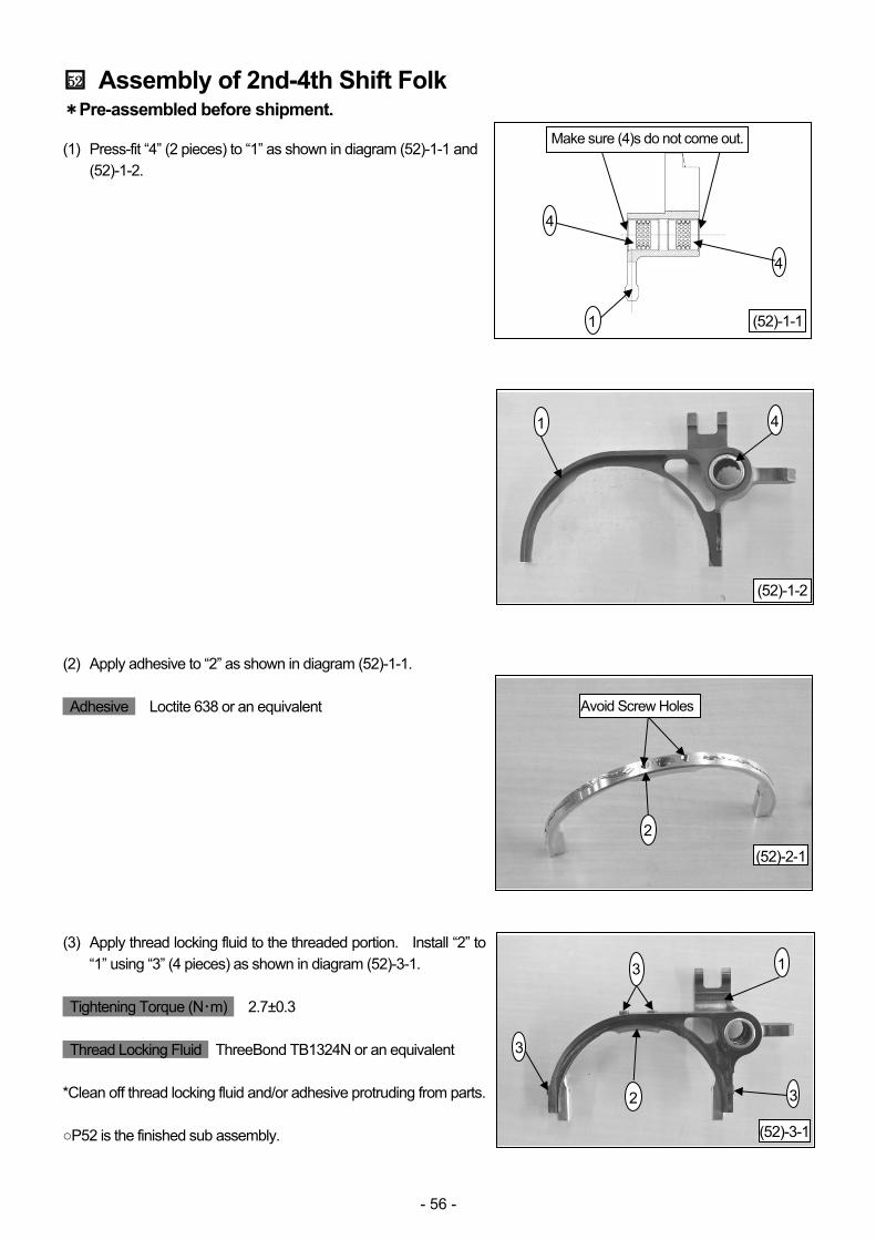
□52 Assembly of 2nd-4th Shift Folk
*Pre-assembled before shipment. (1) Press-fit “4” (2 pieces) to “1” as shown in diagram (52)-1-1 and
(52)-1-2. (2) Apply adhesive to “2” as shown in diagram (52)-1-1. Adhesive Loctite 638 or an equivalent (3) Apply thread locking fluid to the threaded portion. Install “2” to
“1” using “3” (4 pieces) as shown in diagram (52)-3-1. Tightening Torque (N・m) 2.7±0.3 Thread Locking Fluid ThreeBond TB1324N or an equivalent *Clean off thread locking fluid and/or adhesive protruding from parts. ○P52 is the finished sub assembly.
(52)-1-11
4
4
(52)-2-1
(52)-1-2
1 4
(52)-3-1
1
2
3
3
3
2
Make sure (4)s do not come out.
Avoid Screw Holes
- 57 -
□53 Assembly of 6th Shift Folk
*Pre-assembled before shipment. (1) Press-fit “4” (2 pieces) to “1” as shown in diagram (52)-1-1 and
(53)-1-2) (2) Apply adhesive to “2” as shown in diagram (53)-2-1) Adhesive Loctite 638 or an equivalent (3) Apply thread locking fluid to the threaded portion. Install “2” to
“1” using “3” (4 pieces) as shown in diagram (53)-3-1. Tightening Torque (N・m) 2.7±0.3 Thread Locking Fluid ThreeBond TB1324N or an equivalent *Clean off thread locking fluid and/or adhesive protruding from parts. ○P53 is the finished sub assembly.


![ECE Professional Seminar.ppt [Read-Only]](https://static.documents.pub/doc/80x56/61efbcea58f2216ece4d9321/ece-professional-read-only.jpg)


