INSTALLATION, OPERATING AND MAINTENANCE MANUAL Submersible Ballast Pump MANUFACTURED BY Sterling Pumps Pty Ltd 14 Sharnet Circuit PAKENHAM, VICTORIA 3806 AUSTRALIA TELEPHONE: (03) 9729 5044 FAX: (03) 9729 3522 www.sterlingpumps.com.au
Transcript
INSTALLATION, OPERATING
AND MAINTENANCE MANUAL
Submersible Ballast Pump MANUFACTURED BY
Sterling Pumps Pty Ltd 14 Sharnet Circuit
PAKENHAM, VICTORIA 3806 AUSTRALIA
TELEPHONE: (03) 9729 5044
FAX: (03) 9729 3522 www.sterlingpumps.com.au
Installation, Operating & Maintenance Manual
Date: 05/02/2014 Rev: 02 2
ATTENTION: Before unpacking the submersible unit, please read this instruction manual very carefully. This submersible pump unit must be put into operation by qualified technical personnel only and these operation instructions and the effective regulations have to be strictly observed. If you do not pay attention to the operating instructions:
Danger may be created for you and your colleagues
the pump or the pump unit may be damaged
the manufacturer is not liable for damages resulting from this non observance.
PLEASE BE AWARE OF YOUR RESPONSIBILITY TO YOUR FELLOW MAN WHEN WORKING AT THE PUMP OR THE PUMP UNIT.
Installation, Operating & Maintenance Manual
Date: 05/02/2014 Rev: 02 3
CONTENTS
SECTION DESCRIPTION PAGE
01 Safety Instructions 4
02 Introduction to Sterling Submersible Pumping Units 7
03 Unpacking, Handling and Transportation 8
04 Installation Preparation 10
05 Electrical Cable Connection 11
06 Installation 12
07 Connecting to the Electrical Supply 14
08 Commissioning 20
09 Maintenance and Repair 21
Installation, Operating & Maintenance Manual
Date: 05/02/2014 Rev: 02 4
1.0 Safety This operating manual gives basic instructions which are to be observed during installation, operation and maintenance of the submersible pump. It is therefore imperative that this manual is read by the responsible personnel/operator prior to assembly and commissioning. It is always to be kept available at the installation site. It is not only the general safety instructions contained under this main heading “Safety” to be observed, but also the specific information provided under the other main headings such as for the private use.
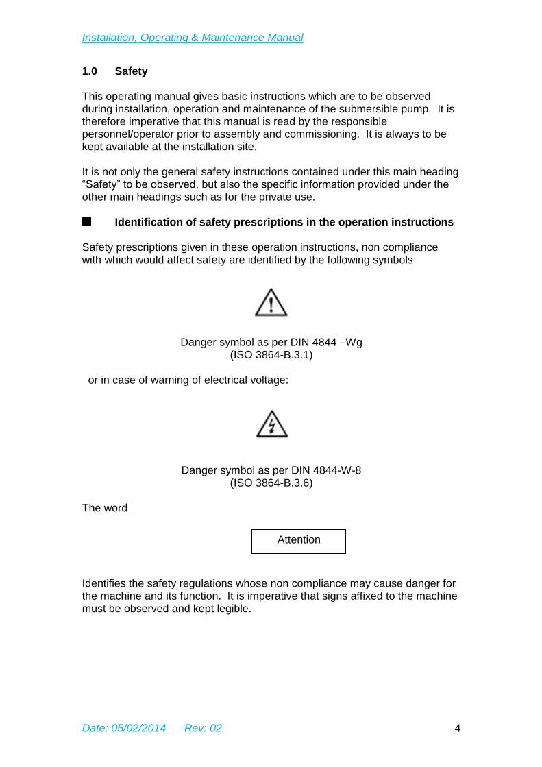
Identification of safety prescriptions in the operation instructions Safety prescriptions given in these operation instructions, non compliance with which would affect safety are identified by the following symbols
Danger symbol as per DIN 4844 –Wg (ISO 3864-B.3.1)
or in case of warning of electrical voltage:
Danger symbol as per DIN 4844-W-8 (ISO 3864-B.3.6)
The word
Identifies the safety regulations whose non compliance may cause danger for the machine and its function. It is imperative that signs affixed to the machine must be observed and kept legible.
Attention
Installation, Operating & Maintenance Manual
Date: 05/02/2014 Rev: 02 5
Qualification and training of personnel The personnel responsible for operation, maintenance, inspection and assembly must be adequately qualified. Scope of responsibility and supervision of the personnel must be exactly defined by the operator. If the staff member does not have the necessary knowledge, they must be trained and instructed which may be performed by the manufacturer on behalf of the operator. Moreover, the plant operator is to make sure that the contents of the operation instructions are fully understood.
Hazards in case of non compliance with the safety instructions Non compliance with the safety instructions may produce a risk to the personnel as well as to the environment and the submersible unit and results in a loss of any right to claim damages. Fore example non compliance may involve the following hazards:
- failure of important functions of the submersible unit, - failure of specified procedures of maintenance and repair, - exposure of people to electrical and mechanical hazards, - endangering the environment
Compliance with regulations,safety at work
When operating the submersible unit the safety instructions contained in this manual, the relevant national accident prevention regulations and any other service and safety instructions issued by the operator to be observed. 1.5 Safety instructions relevant for operation Hazards resulting from electricity are to be precluded (see for example the VDE-specifications and the bye-laws of the local power supply utilities). 1.6 Safety instructions relevant for maintenance, inspection and
assembly work It shall be the operator’s responsibility to ensure that all maintenance, inspection and assembly work is performed by authorized personnel who have adequately familiarized themselves with the subject matter by studying this manual in detail. Any work on the submersible unit shall only be performed when it is at a standstill. It is imperative that the procedure for shutting down the machine described in this manual is to be followed. On completion of work all safety and protective facilities must be re-installed and made operative again. Prior to re-starting the machine, the instructions listed under “putting into operation” are to be observed.
Installation, Operating & Maintenance Manual
Date: 05/02/2014 Rev: 02 6
1.7 Unauthorized alterations and production of spare parts Any modifications may be made to the submersible unit only after consultations with the manufacturer. Using spare parts and accessories authorized by the manufacturer is in the interest of safety. Use of other parts will exempt the manufacturer from any liability. 1.8 Unauthorized mode of operation The reliability of the submersible unit delivered will only be guaranteed if it is used in the manner intended and in accordance with the instructions of this manual. The limit values specified in the data sheet must under no circumstances be exceeded. 1.9 Warranty/guarantee Sterling Pumps guarantee for a long term, satisfactory operation if:
- the submersible unit is installed and operated in compliance with these instructions and under conditions approved by Sterling Pumps,
- modifications only will be carried out with Sterling Pumps agreement.
Installation, Operating & Maintenance Manual
Date: 05/02/2014 Rev: 02 7
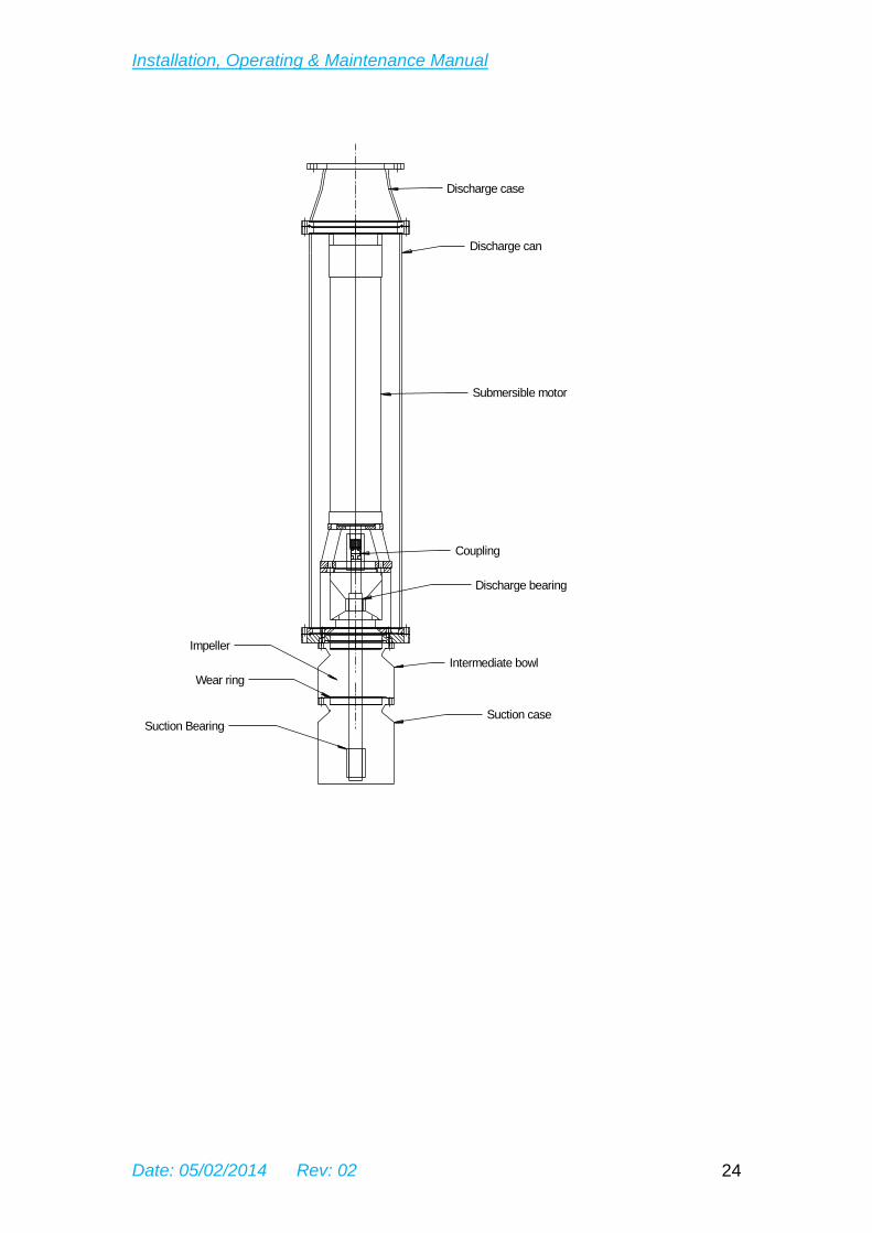
2.0 Introduction Sterling submersible pump units The pumping unit consists of a special under water electric motor Coupled directly to a centrifugal pump. The pump unit is designed to operate completely submerged under water, for pumping clean cold water only. By nature of its application and design, the unit is generally small in diameter, but long, forming an integral “in line” unit suitable for installation under water in relative small diameter wells or sumps. Minimum submergence is particular to individual units and is marked on the pump drawing. 2.1 Electrical supply Electric supply is by lengths of flexible cable which may be single or Four core of sufficient length to suit installation setting depth. The units may be supplied with or without flexible cable attached Depending on customer’s requirements. It is recommended however that Sterling Pumps supply and connect the cable via vulcanised Joint to the motor lead or one length cable, to ensure selection of the power cable is adequate and connection is fully waterproof. In case the cable selection and connection is made by a third party, the cable size needs to be dimensioned according the remarks mentioned under the heading “cable connection” of this manual
The submersible must not be connected to the electrical supply until the full installation of the unit in its location has taken place.
The pump end is designed to operate completely under water and to ensure satisfactory cooling. 2.2 General precautions No components from the pump unit should be removed. Removal will invalidate warranty and no responsibility will be taken by Sterling Pumps to possible personal injuries.
Attention
Installation, Operating & Maintenance Manual
Date: 05/02/2014 Rev: 02 8
3.0 Unpacking, handling and transportation The unloading, transportation and moving of the pump unit has to be carried out under the utmost care. In view of the long cylinder shape of the pump unit it is emphatically stressed, that the pump unit in no case should drop and when laying it down it should be supported at several points over the enter length. Should the pump unit in spite of everything drop during the transportation or become damaged, the unit then shall NOT be installed in the location before consulting our Service department or our agent/sales-engineer.
Attention
Installation, Operating & Maintenance Manual
Date: 05/02/2014 Rev: 02 9
3.1 Unpacking New pump units which are packed for despatch require to be supported in the packing case at several points over the entire length of the unit, by means of suitable wooden “V” blocks. In case units are longer than approximately 2 ½ metres, the “V” blocks will have recesses at approximately the centre of both the pump-end and the motor, enabling lifting straps to be inserted, ensuring that these lifting straps are approximately at the weight centre of the pump-end and the motor (see figure 2). When lifting from the packing case and during all horizontal lifting operations, the lifting straps are to be inserted at the same locations in order to minimise bending action to the unit. No lifting eyes are available due to the cylindrical nature of the unit (narrow). During the horizontal lifting operation, the cable protector and power cable should be positions on the topside of the pump unit and due care should be taken that this will not be clamped between the lifting straps.
3.2 Horizontal to vertical transfer Transfer of the units from horizontal to vertical position should be executed with the utmost care. The discharge flange may be used to lift the pump from horizontal to vertical position. It is recommended that installation handling personnel wear protection gloves and footwear. 3.3 Lifting equiment Lifting equipment depending on pump unit weight can consist of the following: mobile crane, chain block and tackle, electric hoist, overhead bean etc. All lifting equipment must be in a good, safe condition and also be capable of carrying the load involved. The hook of the lift equipment must have a swivel hook. The net bare weight excluding attached power cable will be shown in the GA drawing in this manual. Check that all lifting equipment is suitable for this weight. In case the power cable will be lifted at the same time, the lifting equipment should off be suitable for the additional weight.
Installation, Operating & Maintenance Manual
Date: 05/02/2014 Rev: 02 10
4.0 Installation preparation Take the pump unit out of the case and check if all ordered accessories are included. 4.1 Electrical check on receipt
Check the insulation resistance to earth. This should read to at least 50 Mega ohms with able attached. Examine unit, motor leads and pump cable for possible damage. 4.2 Priming the submersible motor. Ballast pump motors 37kw and below do not require priming unless they have been removed for their installation and placed in long term storage.
Installation, Operating & Maintenance Manual
Date: 05/02/2014 Rev: 02 11
5.0 Electrical cable connection The unit is normally supplied with the required length of power cable jointed by a waterproof connection the motor leads. No terminal box is available on submersible electric motor due to the special purpose use. 5.1 Cable selection If the cable is to be selected and fitted by the customer or a third party, cable selection must take into account:
- the local electrical safety regulations, - the insulation suitability for continuous under water operation, - maximum current consumption of the submersible pump, - voltage drop that will occur over the entire cable length involved.
The maximum voltage drop over the full length of power cables until motor inside terminals should not exceed 5% of nominal volts as mentioned on unit name plate. The earth conductor size must comply to local and/or international standards. Local regulations may require a lower allowable voltage drop. 5.2 Cable joining The cable joints between power cable and motor leads must ensure complete insulation from surrounding water (waterproof) and must be robust enough to prevent damage. Phase connection identification must be transferred to the cable being attached for later use at the well head.
Earth connections must be to the earth core on the motor and also insulated from the surrounding water to prevent corrosion in service.
Attention
Installation, Operating & Maintenance Manual
Date: 05/02/2014 Rev: 02 12
6.0 Installation of the pump unit After the preliminary actions have been taken, the installation of the pump unit in the location may be started with the aid of lifting equipment Lifting equipment must be selected by the installer with consideration of total installed weight including the rising main (column piping) if full of water and also considering the strength of the surrounding ground area on which lifting equipment is positioned. 6.1 Electrical power cable During the installation, all electrical cables should be completely rolled out on the surface, or otherwise coiled away in such a position that personnel cannot stand on it. It is not allowed to stand within the coil(s). During installation the cables need to be guided accordingly. The electric power cable which is attached at the pump unit, is fixed to the supply pipe (rising main) with cable clips at distances 1.5 meter and immediately above or below the flanges or sockets. Care should be taken that the cable will not be pinched between the supply pipe and the well casing. Therefore, when using flanges, these should be provided with a recess of sufficient size adapted to the cable diameter.
Attention
Attention
Installation, Operating & Maintenance Manual
Date: 05/02/2014 Rev: 02 13
6.2 INSTALLATION PROCEDURE
1. The short section of pipe is fitted to the pump discharge flange.
2. Lifting eyes may be fitted to the pipe flange & the Lifting Lugs are
bolted into the lifting eyes.
3. The mounting clamp is installed onto the Caisson flange as. Open the
clamps wide to allow the pump assembly to pass through.
4. Carefully raise the pump/motor assembly and lower through the clamp
until the pipe clamp can be closed and bolted to support the pipe below
the flange
5. Remove the lifting plate and fit to the next section of pipe.
6. Raise the new section of pipe into place and fit to the clamped pipe.
7. After the load has been taken, undo the clamp bolts and open the
clamp wide to allow the pipe flange to pass through. Attach the motor
fluid pipes and motor cable to the column with the straps provided at
1m from the flange each side with care not to crush the pipes or cable.
8. Lower the pump assembly and clamp under the next flange. Repeat
this process until all sections are fitted.
9. Lift the Caisson cover/Well Head assembly into place with the lifting
lugs and fit to the last section of pipe. Take the load and remove the
mounting clamp completely. Lower into place and secure with Caisson
cover bolts.
Installation, Operating & Maintenance Manual
Date: 05/02/2014 Rev: 02 14
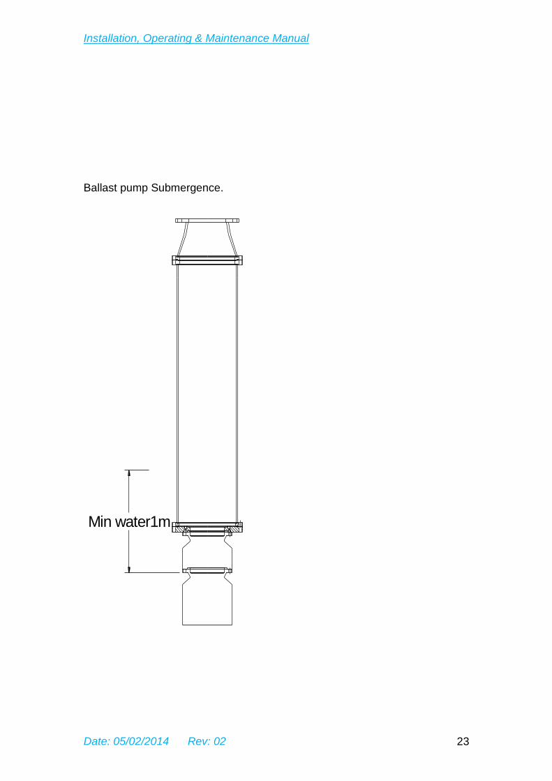
6.3 Caution. It is recommended to make sure before installation that the total length of the rising main is sufficient to install the pump at the required depth in the location. When determining this also take into account the required water column above the submersible pump unit during operation with regard to N.P.S.H characteristics of the well. Since the pump unit is to suspend from the rising main, it is necessary to pay close attention to a solid connection of the pipes and the selection of the required piping and gasket strength must be based on the required working and closed valve pressure and the total installed weight. The pump unit must not be allowed to operate out of the water. The installation depth of the pump unit must be set in such a way that no part of the pump unit will be exposed, even at the lowest liquid level, during operation. 7.0 Connection of the electrical supply
Electrical connections are to be carried out according to the regulations of the local public utilities and to the local standards. Only personnel, authorized correspondingly, may carry out this work.
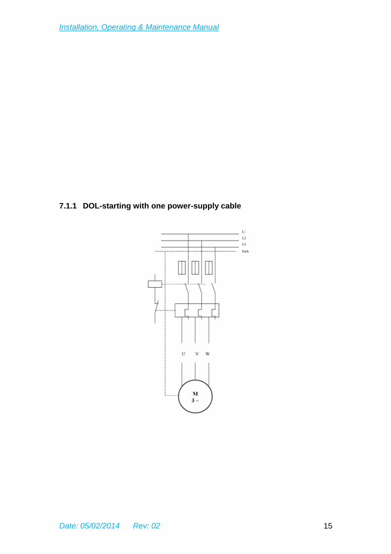
The following connections are possible in case of: 7.1 3-Phase motors The motors are in this case supplied with four or seven motor leads (1 or 2 supply calbes).
Attention
Installation, Operating & Maintenance Manual
Date: 05/02/2014 Rev: 02 15
7.1.1 DOL-starting with one power-supply cable
Installation, Operating & Maintenance Manual
Date: 05/02/2014 Rev: 02 16
7.1.2 Seven lead motors DOL-starting (2 cables parallel)
Installation, Operating & Maintenance Manual
Date: 05/02/2014 Rev: 02 17
7.1.3 Star delta starting
Installation, Operating & Maintenance Manual
Date: 05/02/2014 Rev: 02 18
7.1.4 DOL starting – delta connection in switch board
7.2 Earthing
Attention
Installation, Operating & Maintenance Manual
Date: 05/02/2014 Rev: 02 19
The submersible motor and ints installation must be adequately earthed in accordance with local electrical regulations and international standards. The green/yellow earth cable core of the pump unit must be connected to earth connection within the starting and control equipment and the supply earth point. In addition, all rising main supporting the pump unit should also be earthed to the same point 7.3 Starter control
The trailing cable must be connected to the electrical supply by means of a starter/control system. The following methods can be used: a) direct on line ) b) star delta ) c) auto transformer ) d) soft start ) e) variable frequency ) for the items c), d) and e) ensure ramp time does not exceed 5 seconds.. It is recommended that low water protection is used and other required safety equipment such as overload trip – low volts relay – phase lost relay etc. The low level probe must be installed into a PVC tube enabling this to be checked and also to clean this probe every month if necessary. The maximum overload relay must be selected to ensure the unit will trip inside below mentioned time limits: - 6,0 x FLC 4 to 6 seconds, - 2,0 x FLC Less than 40 seconds, - 1,5 x FLC Less than 80 seconds, - 1,2 x FLC Less than 180 seconds. NOTE: fflc = Full Load Current. 7.3 Adjusting the overload trip
Attention
Installation, Operating & Maintenance Manual
Date: 05/02/2014 Rev: 02 20
Special attention should be paid to the consumed current by the unit and the setting of the overload protection. The current consumption in all three phases of 3-phase motors and in one phase of single phase motors should not be more than the figure indicated on the name plate of the pump unit. As soon as a deviation is observed, the pump unit must be switched off immediately and our technical service or our agent/sales engineer has to be notified. The overload relay must be adjusted to an amperage which is slightly higher, with a maximum of 5% higher, than actually consumed current of the unit, but must never exceed the maximum value mentioned on the name plate. Only full guarantee can be give on the motor if the overload protection complies with our recommendations. 8.0 Commissioning With the unit installed and electrically connected, the following should be carried out. 8.1 Check the correct direction of rotation
It will be noticed no direction of rotation can be indicated on the unit, as the unit must be installed completely under water. The pump unit’s power cable is connected to the electrical circuit by means of a starter executed with the required safety devices. Exchange of 2 out of the 3 phases (excluding the earth phase) changes the direction of rotation of the motor when connected to a 3-phase electrical supply system. 8.2 How to determine the correct direction of rotation: In order to determine the correct direction of rotation, fit a pressure gauge onto the bend of the rising main (column piping) between the pump and the valve. Start the pump with almost closed valve, after pumping flow has been established, close the valve completely for a maximum 60 seconds, read the pressure on the gauge and record this. Then exchange 2 phase (not the earth phase), whereby the pump starts rotating the other direction, establish flow, close valve and again read the pressure on the gauge. The direction of rotation indicating the highest pressure on the gauge is the correct direction and of course the submersible unit should be connected in accordance with this direction of rotation.
Attention
Installation, Operating & Maintenance Manual
Date: 05/02/2014 Rev: 02 21
1. THE UNIT MUST NOT BE OPERATED FOR MORE THAN 2 MINUTES WHEN COMPLETING THE ABOVE CHECKS:
2. THE UNIT MUST NOT BE OPERATED CONTINUOUSLY IN THE REVERSE DIRECTION
CAUTION:
- NEVER let the pump operate with closed valve, except for determination of the correct direction of rotation as mentioned under the above heading “How to determine the correct direction of rotation”, as at close valve condition, the submersible pump does not have adequate cooling and motor windings will be damaged;
- The maximum number of starts per hour allowed for the submersible pump unit with a motor of 3HP and onwards is 6. For submersible pumps with smaller motor sizes 10 starts per hour can be allowed.
8.3 Putting into operation Full details with regard to operation cannot be advised in this section due to the multitude of systems available. However, the following points should be noted: 8.3.1 Over pumping of the well should not occur, 8.3.2 Continual changes of flow should be avoided to minimise disturbance
in the ground strata, 8.3.3 Start/stopping should be minimised, 8.3.4 Surge control must be used to prevent damaging surges during
starting and stopping,
8.3.5 If temperature protection is fitted this should be adjusted to 5°C above indicated temperature,
8.3.6 Check pump performance and amperage input is correct.
Attention
Attention
Attention
Installation, Operating & Maintenance Manual
Date: 05/02/2014 Rev: 02 22
9.0 Maintenance and repair A submersible unit correctly installed will operate for many hours without maintenance, depending on the pumped water quality. 9.1 Checking interval On a half yearly basis the complete installation should be checked for capacity, pressure, voltage, current consumption, insulation and also on safety aspects. 9.2 Storage In case the unit will not be installed immediately after arrival, it is recommended to fill (top up) the motor with emulsion as described under the heading “Priming of the submersible motor for long term storage”. Units supplied by us have already been filled with emulsion, so these units only need to be topped up to compensate for possible leakage of emulsion during transportation. The unit must be stored vertically (motor beneath the pump). In case the unit has been or will be stored outside the location during the winter season, it is desired that this is effected in a FROSTPROOF room. In any case adequate measures must be taken that freezing of the unit is prevented. 9.3 Assistance If further information is desired, please contact our service department or our agent/sales engineer.