Price - $3.00 INSTALLATION, OPERATING AND SERVICE INSTRUCTIONS FOR LEDV SERIES DIRECT VENT OIL FIRED BOILER 81433101R3-3/00 As an ENERGY STAR Partner, Burnham Corporation has determined that the LEDV-1, fired at the 0.60 GPH rate, meets the ENERGY STAR guidelines for Energy efficiency established by the United States Environmental Protection Agency (EPA). For service or repairs to boiler, call your heating contractor. When seeking information on boiler, provide Boiler Model Number and Serial Number as shown on Rating Label. Boiler Model Number LEDV__ - _______ Boiler Serial Number 6 _ _ _ _ _ _ _ Installation Date Heating Contractor Phone Number Address
Transcript
1
Price - $3.00
INSTALLATION, OPERATING ANDSERVICE INSTRUCTIONS FORLEDV SERIES DIRECT VENT
OIL FIRED BOILER
81433101R3-3/00
As an ENERGY STAR Partner, Burnham Corporation has determined that the LEDV-1, fired at the 0.60 GPH rate,meets the ENERGY STAR guidelines for Energy efficiency established by the United States Environmental ProtectionAgency (EPA).
For service or repairs to boiler, call your heating contractor. When seeking information on boiler, provideBoiler Model Number and Serial Number as shown on Rating Label.
Boiler Model Number
LEDV__ - _______Boiler Serial Number
6 _ _ _ _ _ _ _Installation Date
Heating Contractor Phone Number
Address
2
IMPORTANT INFORMATION - PLEASE READ THIS PAGE CAREFULLY
The following terms are used throughout this manual to bring attention to the presence of hazards of various risk levels, or toimportant information concerning product life.
DANGERDO NOT store or use gasoline or other flammable vapors or liquids in the vicinity of this or anyother appliance.If you smell gas vapors, DO NOT try to operate any appliance - DO NOT touch any electricalswitch or use any phone in the building. Immediately, call the gas supplier from a remotelylocated phone. Follow the gas supplier's instructions or if the supplier is unavailable, contact thefire department.
WARNINGImproper installation, adjustment, alteration, service or maintenance can cause property damage,personal injury or loss of li fe. Failure to follow all instructions in the proper order can causepersonal injury or death. Read and understand all instructions, including all those contained incomponent manufacturers man uals which are provided with the appliance b efore ins tall ing,starting-up, operating, maintaining or servicing this appliance. Keep this manual and literature inlegible condition and posted near appliance for reference by owner and service technician.
This boiler requires regular maintenance and service to operate safely. Follow the instructionscontained in this manual. Installation, maintenance, and service must be performed only by anexperienced, skilled installer or service agency. All heating systems should be designed bycompetent contractors and only persons knowledgeable in the layout and installation of hydronicheating systems should attempt installation of any boiler. It is the responsibility of the installingcontractor to see that all controls are correctly installed and are operating properly when theinstallation is completed. Installation is not complete unless a pressure relief valve is installedinto the tapping located on top of appliance - See Section III of this manual for details.
3
NOTICE
This boiler has a limited warranty, a copy of which is printed on the back of this manual.It is the responsibility of the installing contractor to see that all controls are correctly installedand are operating properly when the installation is complete. The warranty for this boiler is validonly if the boiler has been installed, maintained and operated in accordance with theseinstructions.
WARNINGBoiler materials of construction, products of combustion and the fuel contain alumina, silica,heavy metals, carbon monoxide, nit rogen oxides, aldehydes and/or other tox ic or harm fulsubstances which can cause death or serious injury and which are known to the state of Californiato cause cancer, birth defects and other reproductive harm. Always use proper safety clothing,respirators and equipment when servicing or working nearby the boiler.This boiler contains very hot water under high pressures. Do not unscrew any pipe fittings norattempt to disconnect any components of this boiler without positively assuring the water is cooland has no pressure. Always wear protective clothing and equipment when installing, startingup or servicing this boiler to prevent scald injuries. Do not rely on the pressure and temperaturegauges to determine the temperature and pressure of the boiler. This boiler contains componentswhich become very hot when the boiler is operating. Do not touch any components unl ess theyare cool.This boiler must be properly vented and connected to an approved vent system in good c ondition.Serious property damage could result if the boiler is connected to an unapproved vent system .This boiler needs fresh air for safe operation and must be installed so there are provisions foradequate combustion and ventilation air.The interior of the venting and air intake systems must be inspected and cleaned before the startof the heating season and should be inspected periodically throughout the heating season forany obstructions. Clean and unobstructed venting and air intake systems are necessary to allownoxious fumes that could cause injury or loss of life to vent safely and will contribute towardmaintaining the boiler's efficiency.This boiler is supplied with controls which may cause the boiler to shut down and not re-startwithout service - If damage due to frozen pipes is a possibility, the heating system shouldnot be left unatttended in cold weather; or appropriate safeguards and alarms should be installedon the heating system to prevent damage if the boiler is inoperative.This boiler is designed to burn No. 2 fuel oil only. Do not use gasoline, crankcase drainings, orany oil containing gasoline. Never burn garbage or paper in this boiler. Do not convert to anysolid fuel (i. e. wood, coal) or gaseous fuel (i. e. natural gas, LP/propane). All flammable debris,rags, paper, wood scraps, etc., should be kept clear of the boiler at all times. Keep the boiler areaclean and free of fire hazards.All boilers equipped with Burner Swing Door have a potential hazard which can cause severeproperty damage, personal injury or loss of life if ignored. Before opening swing door, turn offservice switch to boiler and disconnect two halves of Burner Swing Door Interlock wiring harnessto prevent accidental firing of burner outside the combustion chamber. Be sure to tighten swingdoor fastener completely and reconnect two hal ves of Burner Swing Door Interlock when serviceis completed.
4
NOTICE
All boilers must be installed in accordance with National, State and Local Plumbing, Heatingand Electrical Codes and the regulations of the serving utilities which may differ from thismanual. Authorities having jurisdiction should be consulted before installations are made.In all cases, reference should be made to the following Standards:
A.
B.
C.
USA BOILERSCurrent Edition of American National Standard ANSI/NFPA 31, “Installation of Oil BurningEquipment”, for recommended installation practices.Current Edition of American National Standard ANSI/NFPA 211, “Chimneys, Fireplaces,Vents, and Solid Fuel Burning Appliances”, For Venting requirements.Current Edition of American Society of Mechanical Engineers ASME CSD-1, "Controls andSafety Devices for Automatically Fired Boilers", for assembly and operations of controlsand safety devices.
CANADIAN BOILERS
A. Current Edition of Canadian Standards Association CSA B139, "Installation Code for OilBurning Equipment", for recommended Installation Practices.
This boiler is suitable for installation on combustible flooring. Boiler cannot be installed oncarpeting.
For o p ti mu m per fo rm an ce a nd serv i ceab i l i ty f rom th is unit adhere to the fo l lowingrecommendations:
A.
B.
C.D.E.
Do not tamper with or alter the unit or controls. Retain your contractor or a competentserviceman to assure that the unit is properly adjusted and maintained.Clean firetubes at least once a year - preferably at the start of the heating season to removesoot and scale. Inside of Combustion Chamber should also be cleaned at the same time.Have Oil Burner and Controls checked at least once a year or as may be necessitated.Do not operate unit with jumpered or absent controls or devices.Do not operate unit if any control, switch, component, or device has been subject to water.
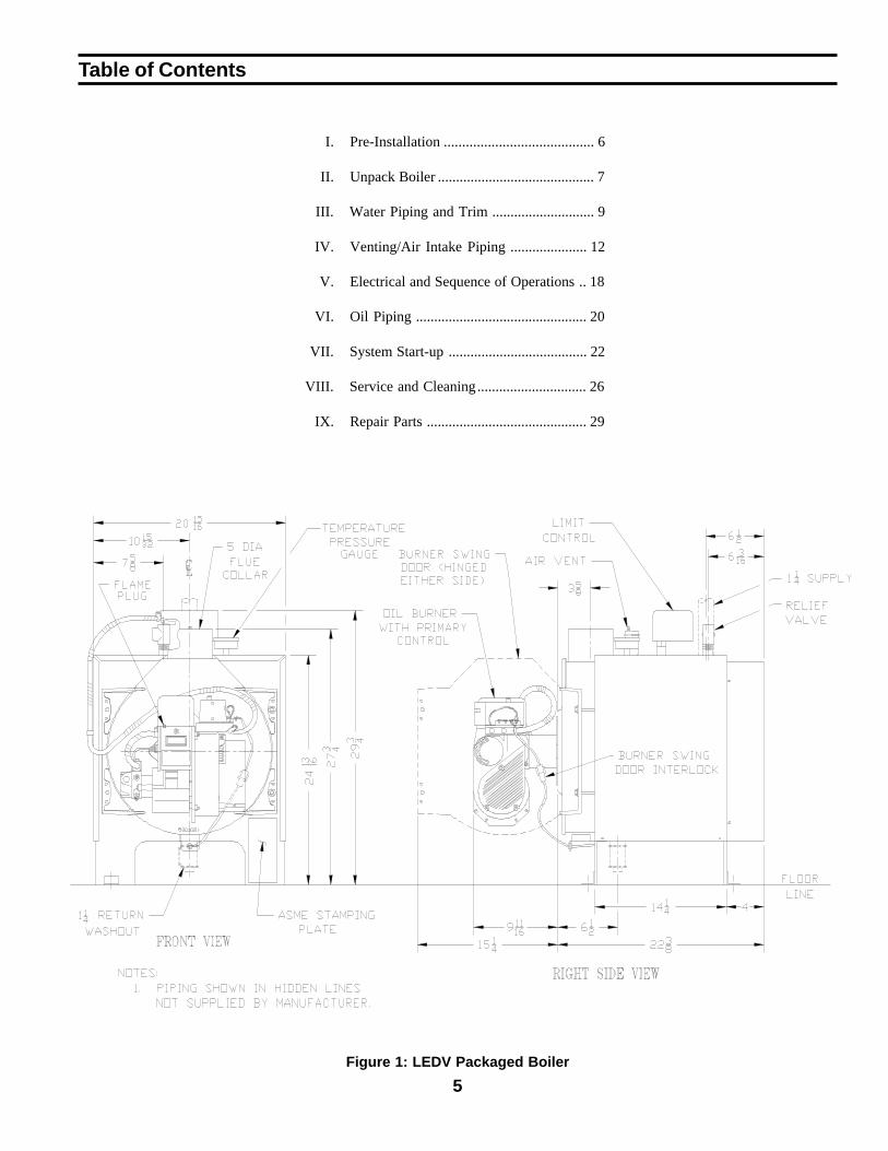
5Figure 1: LEDV Packaged Boiler
Table of Contents
I. Pre-Installation ......................................... 6
II. Unpack Boiler ........................................... 7
III. Water Piping and Trim ............................ 9
IV. Venting/Air Intake Piping ..................... 12
V. Electrical and Sequence of Operations .. 18
VI. Oil Piping ............................................... 20
VII. System Start-up ...................................... 22
VIII. Service and Cleaning.............................. 26
IX. Repair Parts ............................................ 29
6
A. INSPECT SHIPMENT carefully for any signs ofdamage.
1. ALL EQUIPMENT is carefully manufactured,inspected and packed. Our responsibility ceasesupon delivery of crated boiler to the carrier in goodcondition.
2. ANY CLAIMS for damage or shortage in shipmentmust be filed immediately against the carrier by theconsignee. No claims for variances from, orshortage in orders, will be allowed by themanufacturer unless presented within sixty (60)days after receipt of goods.
B. LOCATE BOILER in front of final position beforeremoving crate. See Figure 1. Boiler's approximateshipping weight is 325 pounds.
1. LOCATE so that vent pipe will be short and direct.Refer to Section V. A., General VentingGuidelines.
2. BOILER IS SUITABLE FOR INSTALLATION ONCOMBUSTIBLE FLOOR. Boiler cannot be installedon carpeting.
3. FOR BASEMENT INSTALLATION, provide a solidbase, such as concrete, if floor is not level, or if watermay be encountered on floor around boiler.
4. PROVIDE SERVICE CLEARANCE of at least 24” atfront of boiler for servicing.
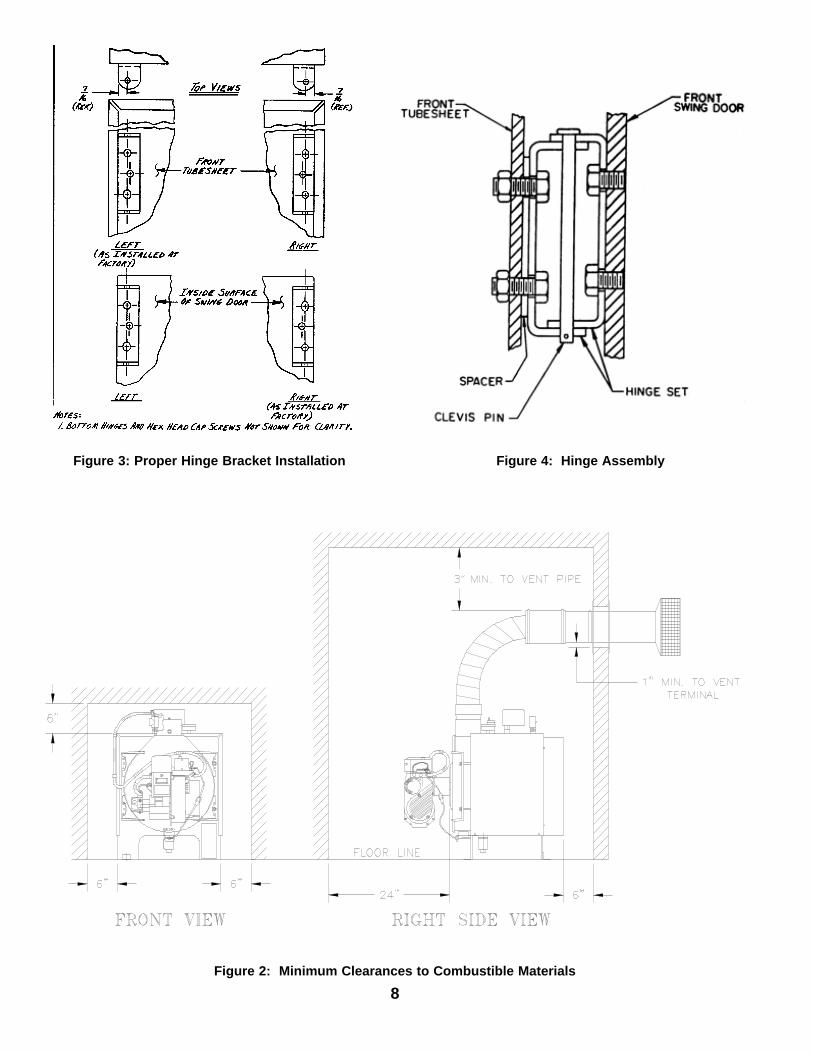
5. For minimum clearances to combustible materials,see Figure 2.
I. Pre-Installation
C. PROVIDE COMBUSTION AIR SUPPLY toaccommodate proper combustion of oil. Local andnational codes may apply and should be referenced.
1. In unconfined spaces (basement) in buildings ofconventional frame, brick, or stone construction,infiltration normally is adequate to provide air forcombustion. An unconfined space is a space whosevolume is greater than or equal to 50 cubic feet per1000 BTUH of the combined input of all airconsuming appliances in the space.
2. In a confined space, combustion air may be ducteddirectly from the outdoors to the burner. Refer toSection IV for installation of air intake duct to theburner.
D. VENTILATION AIR must be provided to maintain theambient temperature at safe limits. Local and nationalcodes may apply and should be referenced.
1. In unconfined spaces (basement) in buildings ofconventional frame, brick, or stone construction,infiltration normally is adequate to provide air forventilation.
2. In confined spaces (closet, etc.) two permanentopenings, one near the top of the enclosure and onenear the bottom, shall be provided. Each openingshall have a free area of not less than 1 sq. inch per1000 BTUH of the total input of all appliances inthe space.
E. Do not install boiler where gasoline or otherflammable vapors or liquids, or sources ofhydrocarbons (i.e. bleaches, cleaners, chemicals,sprays, paint removers, fabric softeners, etc.) are usedor stored.
7
II. Unpack Boiler
CAUTION
Do not drop boiler. Do not bump boiler jacketagainst floor.
A. REMOVE CRATE
1. Remove all fasteners at crate skid.
2. Lift outside container and remove all other insideprotective spacers and bracing. Remove vacuumrelief valve and miscellaneous trim bag containingsafety/relief valve, and pipe fittings.
B. REMOVAL OF BOILER FROM SKID
1. Boiler is secured to base with 2 bolts, 1 at left frontand 1 at right rear. Remove both bolts.
2. Tilt boiler, "walk" boiler backward, and set rearlegs down on floor. Tilt boiler backward, pull skidforward and set front legs down on edge of skid.Install close nipple, tee, and plug in returncoupling. See Section III and Figure 5. Point teetoward permanent return location.
3. Tilt boiler backward and remove skid. Be carefulnot to damage Burner or Jacket.
C. DETERMINE PROPER HINGE LOCATION FORBURNER SWING DOOR. Boiler is shipped withhinges on left side. Approximately 12 inches arerequired on the hinge side for burner clearance. Ifthere will be less than 12 inches from left side of boilerto wall, move hinges to right side (refer to ParagraphD).
D. HINGE LOCATION CHANGE (if required).
1. Pull 2 halves of Burner Swing Door Interlock apart.Swing Door Interlock is connected to R-Wterminals on R8184P Control. Lift HoneywellR8184P Control off of Burner Junction Box anddisconnect wiring harness from burner.
2. Remove 8 sheet metal screws from jacket. Removerear jacket box and bend both sides of JacketWrapper up, see Figure 20.
3. Remove 2 (two) 5/16" - 18 x 3" long hex head capscrews and flat washers from right side of door.Remove 2 hairpin cotter pins and 2 hinge pins fromhinges on left side of door and remove DoorAssembly from boiler. Inspect Front and Rear DoorInsulation Pieces and Combustion Chamber Liner,see Paragraph G.
4. Remove 4 hex nuts from bolts that attach hingesand hinge spacers to left side of Tubesheet. Remove4 hex head cap screws that attach hinges to door.
5. Attach 2 hinge brackets & spacers to Tubesheet and2 hinge brackets to Door on right side of boiler. 3Holes in each Hinge Bracket must line up with 3matching holes in Spacer, Tubesheet or Door. SeeFigure 3. Tighten hex nuts, bolts and screws byhand only.
6. Replace door assembly. Hinge brackets attached todoor must rest on top of hinge brackets attached totubesheet. See Figure 4. Slide hinge pins throughhinges from top and install cotter pins. Close doorand install 5/16" - 18 x 3" long hex head capscrews through flat washers and left side of doorand into tapped holes in tubesheet. Tighten all hexnuts, bolts and screws. When door is installedproperly, it is parallel to Tubesheet when viewedfrom top and sides.
7. Bend sides of Jacket Wrapper down and attach 2Jacket Straps to 4 slots at bottom of Jacket Wrappersides with sheet metal screws. Install Rear JacketBox with 4 sheet metal screws. See Figure 20.
8. Connect wiring harness to burner Junction Box andinstall Honeywell R8184P Control, see WiringDiagram, Figure 15.Reconnect Swing Door Interlock.
E. INSTALL BOILER CONTROL.
1. Pull bulb and capillary tube out of hole in back ofcontrol. Insert bulb in immersion well on top ofboiler and secure control with set screw in control.
2. Secure flexible conduit to Jacket Wrapper side withconduit clamp and sheet metal screw. Conduitmust be on same side of boiler as Swing Doorhinges.
F. MOVE BOILER TO PERMANENT POSITION bysliding or walking.
G. INSPECT FRONT AND REAR DOOR INSULATIONAND COMBUSTION CHAMBER LINER
1. OPEN BURNER SWING DOOR on front of boiler.Use flashlight to inspect insulation secured to frontand rear doors. Inspect ceramic fiber blanketsecured to bottom of combustion chamber. Inspectinner and outer door gaskets. Replace any damagedpieces.
8
Figure 4: Hinge AssemblyFigure 3: Proper Hinge Bracket Installation
TS-98-14-A
Figure 2: Minimum Clearances to Combustible Materials
9
III. Water Piping and Trim
A. Design and install boiler and system piping toprevent oxygen contamination of boiler water.
There are many possible causes of oxygencontamination such as:
1. Addition of excessive make-up water as a result ofsystem leaks.
2. Absorption through open tanks and fittings.
3. Oxygen permeable materials in the distributionsystem.
In order to insure long product life, oxygen sourcesshould be eliminated. This can be accomplished bytaking the following measures:
1. Repairing system leaks to eliminate the need foraddition of make-up water.
2. Eliminating open tanks from the system.
3. Eliminating and/or repairing fittings which allowoxygen absorption.
4. Use of non-permeable materials in the distributionsystem.
5. Isolating the boiler from the system water byinstalling a heat exchanger.
B. Connect System supply and return piping to boiler. SeeFigures 5 and 7. Also consult I=B=R Installation andPiping Guides. Maintain minimum ½ inch clearance fromhot water piping to combustible materials.
1. If this boiler is used in connection with refrigerationsystems, the boiler must be installed so that thechilled medium is piped in parallel with the heatingboiler using appropriate valves to prevent the chilledmedium from entering the boiler, see Figure 6. Alsoconsult I=B=R Installation and Piping Guides.
2. If this boiler is connected to heating coils located inair handling units where they may be exposed to
refrigerated air, the boiler piping must be equippedwith flow control valves to prevent gravitycirculation of boiler water during the operation of thecooling system.
3. If boiler is used with an Alliance Indirect-FiredDomestic Water Heater, install the Alliance as aseparate heating zone. Refer to the AllianceInstallation, Operating, and Service Instructions foradditional information.
4. Use a system bypass if the boiler is to be operated ina system which has a large volume or excessiveradiation where low boiler water temperatures maybe encountered (i.e. converted gravity circulationsystem, etc.).The bypass should be the same size as the supplyand return lines with valves located in the bypassand return line as illustrated in Figures 5 and 7 inorder to regulate water flow for maintenance ofhigher boiler water temperature.Set the by-pass and return valves to a half throttleposition to start. Operate boiler until the systemwater temperature reaches its normal operatingrange.Adjust the valves to maintain 180°F to 200°F boilerwater temperature and greater than 120°F returntemperature. Adjust both valves simultaneously.Closing the boiler return valve while opening the by-pass valve will raise the boiler return temperature.Opening the boiler return valve while closing the by-pass valve will lower the boiler return temperature.
5. A hot water boiler installed above radiation levelmust be provided with a low water cutoff device aspart of the installation.
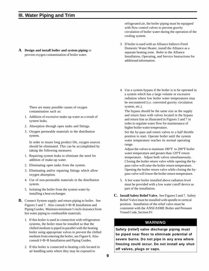
C. Install Safety Relief Valve. See Figures 5 and 7. SafetyRelief Valve must be installed with spindle in verticalposition. Installation of the relief valve must beconsistent with the ANSI/ASME Boiler and PressureVessel Code, Section IV.
WARNING
Safety (relief) valve discharge piping mustbe piped near floor to eliminate potential ofsevere burns. Do not pipe in any area wherefreezing could occur. Do not install any shut-off valves, plugs or caps.
10
Figure 5: Recommended Boiler Piping for Zoning with Valves
D. Install Drain Valve in return piping. See figure 5.
E. Oil, grease, and other foreign materials whichaccumulate in new hot water boilers and a new orreworked system should be boiled out, and thenthoroughly flushed. A qualified water treatmentchemical specialist should be consulted forrecommendations regarding appropriate chemicalcompounds and concentrations which are compatiblewith local environmental regulations.
F. After the boiler and system have been cleaned andflushed, and before refilling the entire system addappropriate water treatment chemicals, if necessary, tobring the pH between 7 and 11.
G. Fill entire heating system with water and vent airfrom system. Use the following procedure on a SeriesLoop System equipped with zone valves. (See Figure5).
1. Close isolation valve in boiler supply piping.
2. Isolate all circuits by closing zone valves orbalancing valves.
3. Attach a hose to bib cock located just below
isolation valve in boiler supply piping. (Note -Terminate hose in five gallon bucket at a suitablefloor drain or outdoor area).
4. Starting with one circuit, open zone valve.
5. Open bib cock.
6. Open fill valve (Make-up water line should belocated directly above isolation valve in boilersupply piping).
7. Allow water to overflow from bucket until dis chargefrom hose is bubble free for 30 seconds.
8. Open zone valve to the second zone to be purged,then close the first. Repeat this step until all zoneshave been purged, but always have one zone open.At completion, open all zone valves.
9. Close bib cock, continue filling the system untilthe pressure gauge reads 12 psi. Close fill valve.(Note - If make-up water line is equipped withpressure reducing valve, system will automaticallyfill to 12 psi.
10. Open isolation valve in boiler supply piping.
11. Remove hose from bib cock.
11
Figure 6: Recommended Piping for Combination Heating & Cooling (Refrigeration) Systems
Figure 7: Recommended Boiler Piping for Zoning with Circulators
12
IV. Venting / Air Intake PipingA. General Guidelines
1. Vent system installation must be in accordance withthese instructions and applicable provisions of localbuilding codes. Contact local building or fire officialsabout restrictions and installation inspection in yourarea.
2. The LEDV Series is designed as a Direct Vent boiler.In this configuration, all air for combustion issupplied directly to the burner from outdoors andflue gases are vented directly outdoors (throughwall). See Figures 10 and 11. The LEDV may beside-wall vented with combustion air supplied fromindoors. This configuration may be used ininstallations where infiltration provides adequate airfor combustion and ventilation. Flue gases are stillvented directly outdoors (through wall).
3. For minimum clearances to combustible materialsrefer to Figure 2.
4. Maximum wall thickness that vent terminal may beinstalled through is 10 inches.
5. Vent Terminal Location (see Figure 8). Locate ventterminal so vent pipe is short and direct. The ventterminal must be located:
a. Not less than 12 inches above grade plus snowaccumulation.
b. Not less than 4 feet below, 4 feet horizontally, or1 foot above any door, window, or gravity airinlet.
c. Not less than 3 feet above any forced air inletlocated within 10 feet.
d. Not less than 2 feet from an adjacent building.
e. Not less than 7 feet above a public walkway.
Figure 8: Vent Terminal Location
13
6. Intake Terminal Location (Direct Vent only) - LocateAir Intake Terminal not less than 12 inches to theleft, right, or bottom of the vent terminal. Do notlocate air intake terminal above vent terminal. Intaketerminal must be at least 12 inches above grade plussnow accumulation. See Figure 9.
7. The LEDV must be vented with 4" Z-Flex DirectOil™ Vent. 20 feet is the maximum vent lengthallowed. The vent pipe is available in 5, 10, 15, and20 foot lengths. Table 1 lists vent part numbers.
Figure 9: Intake Terminal Location
Components of this kit are listed in the Repair PartsSection of this manual.
B. Vent Installation (Direct Vent and Side-Wall Vent)
1. Install Vent Terminal. See Figure 10.
a. After determining the location from previousSection, cut an opening in the wall for the ventterminal.
• Combustible wall: 8 inches diameter hole isrequired to maintain a 1 inch clearance tocombustible materials.
• Non-combustible wall: 6½ inches diameterhole is required.
b. Secure trim plate to outside wall.
c. Insert the vent terminal through the openinguntil the stop bead rest against the trim plate.
d. Slide the inside trim plate assembly (fitted withgear clamp) onto the terminal pipe.
Table 1: Vent Pipe Part Numbers
4" Direct Oil™ Vent Pipe
Pipe Length Burnham Part No.
5 Ft. 8113302
10 Ft. 8113303
15 Ft. 8113304
20 Ft. 8113305
8. The vent system must be completed with the DirectOil™ Vent Kit, which is shipped with the boiler.
14
Figure 10: Vent Installation
Figure 11: Vent Connector, Un-Assembled
15Figure 13: Air Intake Installation
Figure 12: Vent Connector, Assembled
16
e. Secure the inside trim plate to inside wall.
f. Tighten the gear clamp to the terminal pipe.
g. Seal all external joints with a weatherproof caulk.
2. Cut vent pipe to length with a hack saw.
3. Install Vent Connector/Appliance Adaptor. SeeFigures 11 and 12.
a. Apply a continuous bead of high temperatureadhesive/sealant (supplied with boiler) aroundoutside of corrugated pipe of vent connector.
b. Twist vent connector into end of vent pipe.Turn the connector counter-clockwise until it isengaged approximately 4 inches into the innervent pipe and the outer collar of the connectoroverlaps the outside of the vent pipe.
c. Tighten the gear clamp on the outer collar of theconnector.
d. Repeat steps a. through c. with the applianceadapter.
4. Connect vent pipe to boiler.
a. Apply a continuous bead of high temperatureadhesive/sealant (supplied with boiler) to insideof appliance adapter (approximately ½ inchfrom end).
b. Slip appliance adapter over boiler flue collar andtighten gear clamp.
5. Connect vent pipe to terminal.
a. Carefully slide insulation sleeve over ventconnector and vent pipe until gear clamp onsmall end of connector can be accessed.
b. Apply a continuous bead of high temperatureadhesive/sealant (supplied with boiler) on insideof cent connector (approximately ½ inch fromend).
c. Clip connector over vent terminal until it is fullyengaged. Then tighten gear clamp.
d. Slide insulation sleeve over terminal connectionso that connector is completely covered.
e. Secure each end of insulation sleeve with thegear clamps provided.
6. Secure vent pipe in position with pipe straps.
a. All horizontal runs must rise at least ¼ inch perfoot toward vent terminal.
b. Avoid any sags or dips in vent pipe.
C. Air Intake Installation (Direct Vent only)See Figure 13.
1. General
a. Use 4 inch diameter single wall metal pipe andfittings available at most heating distributors.Maximum allowable air intake length is 40equivalent feet. Each elbow is equal to 6equivalent feet.
b. Start at Burner. Work toward air intake terminal.
c. Maintain minimum of ¼ inch per foot slope inhorizontal run to air intake terminal. Slopedown toward air intake terminal.
d. Seal all joints gas-tight, using silicone caulk orself-adhesive aluminum tape.
2. After determining location, cut a hole in the wall toaccept 4 inch air intake pipe.
3. Remove the black plastic inlet cover from the rightside of the Beckett AFII burner.
4. Mount the vacuum relief valve tee assembly or 90°elbow into the burner inlet ring. See Figure 13.
a. Secure with at least three (3) sheet metal screwsevenly spaced around the burner inlet ring.
b. Assemble the vacuum relief valve balanceweight onto the gate. Refer to the vacuum reliefvalve manufacturer's instructions.
c. Mount the vacuum relief valve into the tee andfasten with a screw and nut in collar tabs. Toensure proper operation, the gate must be levelacross the pivot point and plumb. Refer tovacuum relief valve manufacturer's instructions.
5. Install remainder of air intake, securing each jointwith at least three (3) sheet metal screws evenlyspaced.
17
6. Install air intake terminal. See Figure 13.
7. Seal all external joints with weatherproof caulk.
D. Air Intake Installation (Indoor Air for Combustion)
1. Remove the black plastic inlet cover from the rightside of the Beckett AFII burner.
2. Attach the Air Intake Terminal directly to the burnerintake collar.
3. Discard the Vacuum Relief Valve.
Alternate to 1., 2. and 3.:Keep the black plastic inlet cover in place anddiscard the Air Intake Terminal and the VacuumRelief Valve.
18
V. Electrical and Sequence of Operations
A . ELECTRICAL
1. Install wiring and ground boiler in accordance withrequirements of authority having jurisdiction, or inabsence of such requirements the NationalElectrical Code, ANSI/NFPA 70, and/or the CSAC22.1 Electric Code.
2. A separate electrical circuit should be run from themain electrical service with a fused disconnectswitch in the circuit.
3. Wiring should conform to Figure 15.
B. SEQUENCE OF OPERATIONS
1. General. A call for heat by the thermostatenergizes the L8148A limit control which in turnenergizes the R8184P primary control to turn onthe burner. The circulator will operate as long asthere is a call for heat. If the call for heat is notsatisfied and the high limit setting is reached, thecirculator will continue to operate, and the burnerwill stop until the high limit circuit is closed by adrop in boiler water temperature.
2. L8148A Combination Limit control.The switching action within the L8148A controlhas one setting, the high limit. The switching relayis controlled by the low voltage room thermostat.On a call for heat, the relay contacts close tocomplete the line voltage circulator circuit and alsothe burner circuit if the boiler water temperature isbelow the high limit setting. The high limit switchshuts off the burner if boiler water temperatureexceeds the high limit setting. See Figure 14.
3. R8184P Oil Primary Control.The R8184P operates the oil burner motor, solenoidoil valve, and the ignition transformer in responseto a call for heat from the L8148A limit control.
a. A call for heat will energize the burner motor
and ignition transformer.
b. After a 15 second pre-purge period, in whichtime a draft is established in the flueways, theoil valve is opened.
c. If the burner ignites within 15 seconds from thetime the oil valve opens and the CAD cell sensesa flame, the burner will operate until the call forheat is satisfied or the setting of the high limit isreached.
d. A manual reset button is provided to reset thesafety switch after lockout.
e. When the call for heat ends, or the CAD cellfails to sense a flame, the oil valve will close.The combustion blower will continue to operatefor a postpurge period of approximately two (2)minutes.
4. CAD Cell.The Beckett AFII burners used on the LEDV Seriesare supplied with a C554A Cadmium Sulfide (cadcell) Flame Detector to monitor the burner flameand shut down the burner on ignition failure or onflame failure during the run cycle. On eitherfailure, the manual reset button on the R8184P willbe tripped.
Figure 14: Control Differential
19
Figure 15: Schematic Wiring Diagram
20
VI. Oil Piping
A. General
1. Use flexible oil line(s) so that Swing Door can beopened without disconnecting oil supply.
2. A supply line fuel oil filter is recommended as aminimum for all firing rates but a pleated paperfuel oil filter is recommended for the lowest (.6GPH) firing rate application to prevent nozzlefouling.
3. Use Flared fittings only. Do not use compressionfittings.
4. Use of a high efficiency micron oil filter (Garber orequivalent) in addition to conventional filter ishighly recommended.
B. Single-pipe Oil Lines.
1. Standard burners are provided with single-stage3450 rpm fuel units with the bypass plug removedfor single-pipe installations.
2. The single-stage fuel unit may be installed single-pipe with gravity feed or lift. Maximum allowablelift is 8 feet. See Figure 16.
Figure 16: Single-Pipe Installation
TABLE 2: SINGLE-STAGE UNITS (3450 RPM)TWO-PIPE SYSTEMS
Lift "H"(See Fig. 16)
Maximum Length of Tubing"H" + "R" (See Figure 16)
3/8" ODTubing (3 GPH)
1/2" ODTubing (3 GPH)
0' 84' 100'
1' 78' 100'
2' 73' 100'
3' 68' 100'
4' 63' 100'
5' 57' 100'
6' 52' 100'
7' 47' 100'
8' 42' 100'
9' 36' 100'
10' 31' 100'
11' 26' 100'
12' 21' 83'
13' --- 62'
14' --- 41'
21
C. Two-Pipe Oil Lines.
1. For two-pipe systems where more lift is required,the two-stage fuel unit is recommended. Table 2(single-stage) and Table 3 (two-stage) showallowable lift and lengths of 3/8-inch and ½-inchOD tubing for both suction and return lines. Referto Figure 17.
TABLE 3: TWO-STAGE UNITS (3450 RPM)TWO-PIPE SYTEMS
Lift "H"(See Fig. )
Maximum Length of Tubing"H" + "R" (See Figure)
3/8" ODTubing (3 GPH)
1/2" ODTubing (3 GPH)
0' 93' 100'
2' 85' 100'
4' 77' 100'
6' 69' 100'
8' 60' 100'
10' 52' 100'
12' 44' 100'
14' 36' 100'
16' 27' 100'
18' --- 76'
Figure 17: Two-Pipe Installation
22
VII. System Start-up
A. ALWAYS INSPECT INSTALLATION BEFORESTARTING BURNER.
B. FILL HEATING SYSTEM WITH WATER. Refer toSection III, G.
C. CHECK CONTROLS, WIRING AND BURNER to besure that all connections are tight and burner is rigid,that all electrical connections have been completed andfuses installed, and that oil tank is filled and oil lineshave been tested.
D. LUBRICATION — Follow instruction on burner andcirculator label to lubricate, if oil lubricated. Mostmotors currently used on residential type burnersemploy permanently lubricated bearings and thus donot require any field lubrication. Water lubricatedcirculators do not need field lubrication.
Do not over-lubricate. This can cause as much troubleas no lubrication at all.
E. SET CONTROLS with burner service switch turned“OFF”.
1. SET ROOM THERMOSTAT about 10° aboveroom temperature.
2. PRESS RED RESET BUTTON on R8184P OilPrimary Control and release.
3. Set high limit dial on L8148 at temperature to suitrequirements of installation.
F. BURNER START-UP
1. VERIFY burner settings.
a. Refer to Table 4.
2. Open all shut-off valves in the oil supply line to theburner.
3. Attach a plastic hose to fuel pump vent fitting andprovide a container to catch the oil.
4. REMOVE GAUGE PORT PLUG from fuel pumpand install pressure gauge.
5. REMOVE TEST PLUG IN FLUE COLLAR.
6. Close the service switch to start the burner. If theburner does not start immediately, check themanual overload switch on the motor, if soequipped, and the safety switch of the burnerprimary control.
WARNING
All boilers equipped with burner swing door have a potential hazard which can cause severeproperty damage, personal injury or loss of life if ignored. Before opening swing door, turn offservice switch to boiler to prevent accidental firing of burner outside the combustion chamber.Be sure to tighten swing door fastener completely when service is completed.
7. Bleed the fuel unit when the burner motor startsrotating. To bleed, loosen the vent fitting (withplastic hose attached) and catch the oil in an emptycontainer. Continue to bleed for 15 seconds afteroil is free of air bubbles. Tighten the vent fittingwhen all the air is purged. NOTE: Bleeding mightnot be necessary with a two pipe system. Whenvent fitting is closed, burner flame should startimmediately.
8. ADJUST OIL PRESSURE
a. Locate oil pressure adjusting screw and turnscrew to obtain 140 PSIG pressure.
b. DO NOT REMOVE PRESSURE GAUGE untillater.
9. ADJUST AIR SETTING on burner for a lightorange colored flame. Use a smoke tester andadjust air for minimum smoke (not to exceed#1) with a minimum of excess air. Make finalcheck using suitable instrumentation to obtain aCO
2 of 11.5 to 12.5%. These settings will assure a
safe and efficient operating condition. If the flameappears stringy instead of a solid fire, try anothernozzle of the same type. Flame should be solid andcompact.
10. TURN "OFF" BURNER BY OPENING SERVICESWITCH. Remove pressure gauge. Install gaugeport plug and tighten. Re-start burner.
11. HINTS ON COMBUSTION
a. NOZZLES — Although the nozzle is arelatively inexpensive device, its function iscritical to the successful operation of the oilburner. The selection of the nozzle supplied
with the microTEKDV boiler is the result ofextensive testing to obtain the best flame shapeand efficient combustion. Other brands of thesame spray angle and spray pattern may be usedbut may not perform at the expected level ofCO
2 and smoke. Nozzles are delicate and should
be protected from dirt and abuse. Nozzles aremass-produced and can vary from sample tosample. For all of those reasons a spare nozzle isa desirable item for a serviceman to have.
b. FLAME SHAPE — Looking into thecombustion chamber through the flame plughole, the flame should appear straight with nosparklers rolling up toward the top of thechamber. If the flame drags to the right or left,sends sparklers upward or makes wet spots onthe rear door insulation piece, the nozzle shouldbe replaced. If the condition persists look forfuel leaks, air leaks, water or dirt in the fuel asdescribed below.
c. FUEL LEAKS — Any fuel leak between thepump and the nozzle will be detrimental to goodcombustion results. Look for wet surfaces in theair tube, under the transformer, and around theair inlet. Any such leaks should be repaired asthey may cause erratic burning of the fuel and inthe extreme case may become a fire hazard.
d. AIR LEAKS — Any such leaks should berepaired, as they may cause erratic burning ofthe fuel and in extreme cases may become a firehazard.
There are many possible causes of air leaks inoil lines such as:
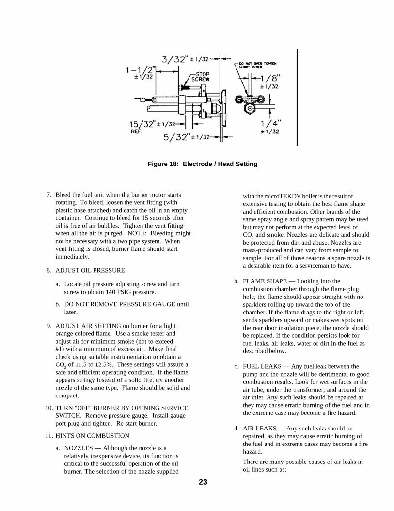
Figure 18: Electrode / Head Setting
24
i. Fitting leaks due to mis-flared tubing ordamaged fitting.
ii . Fuel line leak due to crushed or bent tubing.
iii. Filter connection leaks.
iv. Tank connection leaks.
There are various test kits available to traceair leaks, such as electronic sight glasses.Follow the manufacturers' instructions tofind air leaks.
The following actions can eliminate air leaks:
i . Bleed pump as detailed in System Start-UpSection of this manual.
ii . Replace flare fittings.
iii . Replace oil supply line.
iv. Repair oil filter leaks.
v. Replace or repair tank fittings.
e. GASKET LEAKS — If 11.5 to 12.5% CO2 with
a #1 smoke cannot be obtained in the breeching,look for air leaks around the flue collar. Such airleaks will cause a lower CO
2 reading in the
breeching. The smaller the firing rate thegreater effect an air leak can have on CO
2
readings.
f. DIRT — A fuel filter is a good investment.Accidental accumulation of dirt in the fuelsystem can clog the nozzle or nozzle strainerand produce a poor spray pattern from thenozzle. The smaller the firing rate, the smallerthe slots become in the nozzle and the moreprone to plugging it becomes with the sameamount of dirt.
g. WATER — Water in the fuel in large amountswill stall the fuel pump. Water in the fuel insmaller amounts will cause excessive wear onthe pump, but more importantly water doesn’tburn. It chills the flame and causes smoke andunburned fuel to pass out of the combustionchamber and clog the flueways of the boiler.
h. COLD OIL — If the oil temperatureapproaching the fuel pump is 40°F or lowerpoor combustion or delayed ignition may result.Cold oil is harder to atomize at the nozzle.Thus, the spray droplets get larger and the flameshape gets longer. An outside fuel tank that isabove grade or has fuel lines in a shallow bury isa good candidate for cold oil. The best solution
is to bury the tank and lines deep enough tokeep the oil above 40°F.
i. HIGH ALTITUDE INSTALLATIONS — Airsettings must be increased at higher altitudes.Use instruments and set for 11.5 to 12.5% CO
2.
j. START-UP NOISE — Late ignition is the causeof start-up noises. If it occurs recheck forelectrode settings, flame shape, air or water inthe fuel lines.
k. SHUT DOWN NOISE — If the flame runs outof air before it runs out of fuel, an after burnwith noise may occur. That may be the result ofa faulty cut-off valve in the fuel pump, or it maybe air trapped in the nozzle line. It may takeseveral firing cycles for that air to be fullyvented through the nozzle. Water in the fuel orpoor flame shape can also cause shut downnoises.
G. TEST CONTROLS
WARNING
Before installation of the boiler is consideredcomplete, the operation of the boiler controlsshould be checked, particularly the primarycontrol and high limit control.
1. CHECK THERMOSTAT OPERATION. Raise andlower thermostat setting as required to start andstop burner.
2. VERIFY PRIMARY CONTROL SAFETYFEATURES using procedures outlined inInstructions furnished with control (See back ofControl Cover) or Instructions as follows:
25
FOR HEATING SERVICEMAN ONLY
a. Simulate flame failure:• Follow the starting procedure to turn on the
burner.• Close the hand valve in the oil supply line.
• Safety switch should lock out inapproximately 15 seconds. Ignition shouldstop and oil valve should close. Blower willstop after postpurge period.
• Push red reset button to reset safety switch.
b. Simulate ignition failure:
• Follow the starting procedure to turn on theburner, but do not open the oil supply handvalve.
• Safety switch should lock out inapproximately 15 seconds. Ignition andmotor should stop and oil valve shouldclose.
• Push red reset button to reset safety switch.
c. Simulate power failure:
• Follow the starting procedure to turn on theburner.
• With the burner running, turn off the powerto the system by tripping the circuit breakeror removing the fuse.
• Burner should stop.
• Restore power. Burner should start.
d. If system does not operate as described, go to theTROUBLESHOOTING AND MAINTENANCEsection.
3. VERIFY HIGH LIMIT OPERATION.
a. Adjust thermostat to highest setting.
b. Observe temperature gauge. When temperatureis indicated, adjust limit to setting belowobserved temperature. Burner should stop.
c. Adjust limit to setting above observed
temperature. Burner should start.
d. Adjust thermostat to lowest setting. Adjust limitto desired setting.
4. CHECK LOW WATER CUTOFF (if so equipped).
a. Adjust thermostat to highest setting.
b. With boiler operating, open drain valve andslowly drain boiler.
c. Burner should stop when water level dropsbelow low water cutoff probe. Verify limit,thermostat or other controls have not shut offboiler.
d. Adjust thermostat to lowest setting. Refillboiler.
H. Boiler is now ready to be put into service.
A leaky system will increase the volume of make-upwater supplied to the boiler which can significantlyshorten the life of the boiler. Entrained in make-upwater are dissolved minerals and oxygen. When thefresh, cool make-up water is heated in the boiler theminerals fall out as sediment and the oxygen escapesas a gas. Both can result in reduced boiler life. Theaccumulation of sediment can eventually isolate thewater from contacting the steel. When this happensthe steel in that area gets extremely hot and eventuallycracks. The presence of free oxygen in the boilercreates a corrosive atmosphere which, if the concen-tration becomes high enough, can corrode the steelthrough from the inside. Since neither of these failuretypes are the result of a manufacturing defect thewarranty does not apply. Clearly it is in everyone’sbest interest to prevent this type of failure. Themaintenance of system integrity is the best method toachieve this.
26
Section VIII: Service and Cleaning
A. General. Inspection, service and cleaning should beconducted annually. Turn off electric power and closeoil supply valve while conducting service ormaintenance.
B. Firetubes and Combustion Chamber.
1. CLEAN THE FIRETUBES
a. For access to fireside of boiler, pull two halvesof Burner Swing Door Interlock wiring harnessapart, remove fasteners holding door closed andopen swing door.
b. Prior to cleaning boiler, lay a protective cloth orplastic over combustion chamber liner.
c. Using a 1 1/2" diameter wire brush (30"handle), clean firetubes. Measure 15" from endof brush opposite handle, and mark handle. DONOT allow this mark to go past front end offiretube during cleaning, or brush will hit reardoor insulation piece.
2. CLEAN THE COMBUSTION CHAMBER
Using wire or fiber bristle brush, clean inside ofcombustion chamber. DO NOT let brush hit reardoor insulation piece or combustion chamber liner.
3. AFTER CLEANING
a. Vacuum debris inside bottom of rear door,remove protective cloth, and vacuum remainingfireside of boiler as necessary. BE CAREFULnot to damage liner or rear door insulation
piece. Inspect front and rear door insulationpieces, front door gaskets and combustionchamber liner for damage. Replace any damagedpieces.
4. CLOSE BOILER
CAUTION: Do not start burner unless burner swingdoor is securely closed. Close door, install fasteners,and tighten securely. Door should be parallel totubesheet when viewed from top and sides.Reconnect two halves of Swing Door Interlock.
C. Vent/Air Intake System. Inspect for obstructions,soot accumulation, proper support, and deterioration ofpipe, fittings, and joints.
1. Inspect inside of vent pipe.
a. Disconnect appliance adapter from boiler fluecollar.
b. Remove any obstructions and clean with a wirebrush as required.
c. Reconnect appliance adapter to boiler flue collaras detailed in Section IV: Venting/Air IntakePiping.
2. Clean terminal screens. Terminals must be free ofobstruction, undamaged, with screens securely inplace.
3. Terminal and wall thimbles (if used) must beweather-tight.
4. Pipe must be full round shape, and show no damagefrom impact or excessive temperature.
5. Pipe must be supported at minimum 5 foot intervalsand must not sag.
6. All vent joints must be secure and watertight.
7. All air intake joints must be secure and airtight.
D. Burner.
1. Replace the oil supply line filter.
WARNING
All boiler service and cleaning must be completed with burner service switch turned off. Boilersequipped with burner swing door have a potential hazard which can cause severe propertydamage, personal injury or loss of l ife if ignored. Before opening swing door, turn off serviceswitch to boiler to prevent accidental firing of burner outside the combustion chamber. Be sure totighten swing door fasteners completely when service is completed.
27
2. Remove and clean the pump strainer (if applicable).
3. Replace the nozzle with an equivalent nozzle. SeeTable 4.
4. Clean and inspect the electrodes for damage,replacing any that are cracked or chipped.
5. Clean the combustion head of all lint and soot.
6. Inspect the transformer cables and connectors.
7. Remove and clean the cad cell.
8. Clean the blower wheel and the air control of anylint.
9. Check all wiring for secure connections orinsulation breaks.
10.Re-adjust the burner as detailed in Section VII:System Start-up, Paragraph F.
E. Controls. Test Controls for proper operation asdetailed in Section VII: System Start-up, Paragraph G.
F. Low water cutoff (if so equipped).
1. Float Type
a. Monthly Blowoff. During the heating season, if
an external float type low water cutoff is on theboiler, the blow off valve should be opened oncea month (use greater frequency where conditionswarrant), to flush out the sediment chamber sothe device will be free to function properly.
b. Annual Service. Float type low water cutoffsshould be dismantled annually by qualifiedpersonnel, to the extent necessary to insurefreedom from obstructions and properfunctioning of the working parts. Inspectconnecting lines to boiler for accumulation ofmud, scale, etc., and clean as required.Examine all visible wiring for brittle or worninsulation and make sure electrical contacts areclean and that they function properly. Givespecial attention to solder joints on bellows andfloat when this type of control is used. Checkfloat for evidence of collapse and check mercurybulb (where applicable) for mercury separationor discoloration.
2. Probe Type (Annual Service). Probe type LWCOshould be removed once a year, examined andcleaned of any dirt accumulations to assure properoperations. Do not attempt to repair mechanisms inthe field. Complete replacement mechanisms,including necessary gaskets and installationinstructions, are available from the manufacturer.
28
Service Notes
29
IX. Repair Parts
All LEDV Series Repair Parts may be obtained through your local Burnham Wholesale Distributor. Shouldyou require assistance in locating a Burnham Distributor in your area, or have questions regarding the avail-ability of Burnham products or repair parts, please contact your Burnham Regional Sales Office as listedbelow.
Burnham Corporation Regional Offices
A. Burnham Corporation - Centr al & Western R egio nsP.O. Box 3079La ncaster, PA 17604 -3079Phone: (717) 481 -8400FAX: (717) 481 -8408
C. Burnham Corporation - Metropoli tan RegionP.O. Box 3079Lancas ter, PA 17604-3079Phone: (717) 481-8400FAX: (717) 481-8409
B. Burnham Sales Cor poration - Northeast Region19 -27 Myst ic AvenueSomerv il le, MA 02145Phone: (617) 625 -9735FAX: (617) 625 -9736
D. Burnham Co rporat ion - Mid-Atlant ic RegionP.O. Box 3079La ncaster, PA 17604 -3079Phone: (717) 481 -8400FAX: (717) 481 -8409
30
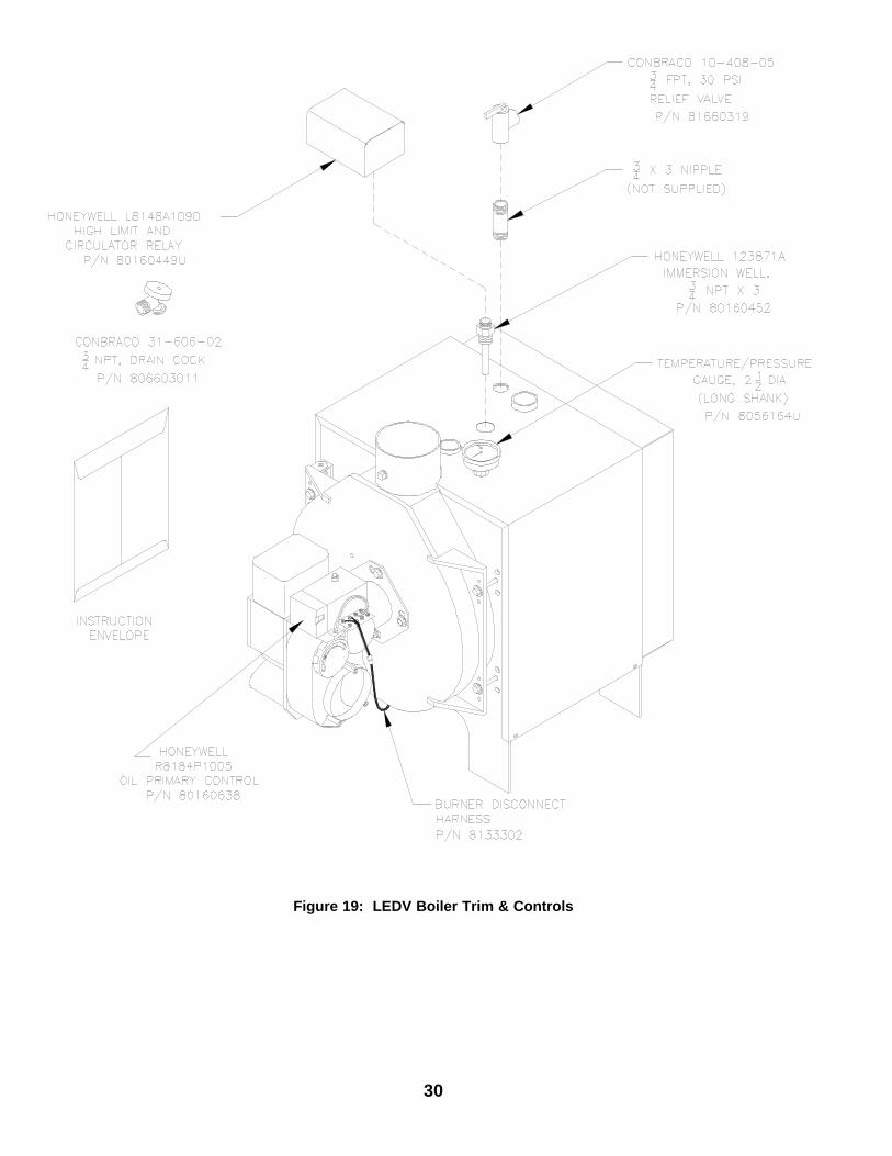
Figure 19: LEDV Boiler Trim & Controls
31Figure 20: LEDV Boiler Jacket & Insulation
32
Figure 21: LEDV Bare Boiler Assembly
33
Fig
ure
22:
Ven
t Kit
Rep
air
Par
ts
34
Figure 23: Beckett AFII Oil Burner Repair Part
For replacement oil burner parts, contact your wholesaler or the burner manufacturer: R.W. Beckett Co., P.O. Box 1289, Elyria, OH 44036(216) 327-1060 or (800) OIL BURN(645-2876)


![lyceumpasspapers.files.wordpress.com...2013/05/08 · a bladder with a cavity. leaves with two halves that interlock. a hallow tube (pitcher). [Total = 2 x 10 = 20 marks] Part If](https://static.documents.pub/doc/80x56/5eaa02057579260dd0263dcd/-20130508-a-bladder-with-a-cavity-leaves-with-two-halves-that-interlock.jpg)


