38
INSTALLATION & OPERATING INSTRUCTIONS SCR FLX SERIES INDUSTRIAL BATTERY CHARGERS
INSTALLATION & OPERATING
INSTRUCTIONS
SCR FLX SERIES
INDUSTRIAL BATTERY CHARGERS


PACIFIC CHLORIDE ®
Exide TechnologiesChloride Motive PowerP.O. Box 1, Salford RoadOver Hulton, Bolton BL5 1DDUnited KingdomTel: 44.1204.661.230Fax: 44.1204.652.100
GNB Industrial PowerMotive Power8301 Keele StreetMaple, OntarioCanada L6A 1T2Tel: 905.669.9326Fax: 905.669.7688
GB-3889 RPT 11/01
GNB Industrial PowerMotive Power829 Parkview BoulevardLombard, IL 60148-3249U.S.A.Tel: 877.GNB.INFOFax: 630.691.7869
Printed on recycled paper
www.gnb.com


Instr. 4770-65-95005-10 Page Rev 15/08/2002
1
TABLE OF CONTENTS
TITLE PAGE
1.0 IMPORTANT OPERATING AND SAFETY INSTRUCTIONS 2
2.0 INTRODUCTION 3
3.0 RECEIVING CHARGER 3
4.0 LOCATION AND INSTALLATION OF CHARGER 3
4.1 Stacking 3
5.0 AC ELECTRICAL SUPPLY 3
5.1 AC Fuse Mounting 3
5.2 Input Voltage Change 3
5.3 AC Voltage Connections 7
5.4 Ground connection 7
6.0 DC OUTPUT 7
7.0 APPLICATION 8
7.1 Display and Fault Codes 8
7.2 Options 8
TABLE 2 - SINGLE PHASE RATINGS 9
TABLE 3 - THREE PHASE RATINGS 11
8.0 CABINET OUTLINE/DIMENSIONS 13
9.0 SCRFLX CHARGER OPERATION 14
9.1 SCRFLX Charger Functional Description 15
10.0 CHARGE TIME 16
11.0 AC POWER FAILURE 16
12.0 MAINTENANCE 16
13.0 TROUBLESHOOTING 17
APPENDIX A: SCRFLX BATTERY CHARGERS. LIST OF DISPLAY INDICATIONS 19
APPENDIX B: ELECTRICAL SCHEMATIC DRAWINGS 21
Instr. 4770-65-95005-10 Page 2
SCRFLX SERIES INDUSTRIAL BATTERY CHARGERS
1.0 IMPORTANT OPERATING AND SAFETY INSTRUCTIONS
SAVE THESE INSTRUCTIONS
a) Before using the battery charger, read all the instructions in addition to the CAUTION, WARNING, and DANGERmarkings on the charger, battery and all the associated equipment.
b) Do not touch uninsulated parts of the DC output connector or the battery terminals, as there is a possibility ofelectric shock.
c) Connect or disconnect the battery plug only when the charger output is off; ALWAYS press the STOPpushbutton before unplugging the battery to prevent arcing or burning.
d) If the battery is unplugged during charging, the charger will indicate “OFF”. To restart the charger, plug in the nextbattery.
e) Only qualified personnel should operate or service this equipment.
f) De-energize all AC and DC power connections before servicing this unit. If injury does occur, apply the prescribedtreatment for electrical shock and obtain medical attention immediately.
g) The charger is NOT for outdoor use. Do not expose the charger to rain or snow.
h) This charger is factory set to charge flooded lead-acid batteries only. Operating environment should not containany contaminations that may cause corrosion or contamination that would degrade the performance of a charger.
i) Do not operate this unit if it has received a sharp blow, been dropped or otherwise damaged. Take it to a qualifiedGNB service center.
j) Do not disassemble the charger. Have the charger examined by a GNB service representative or local qualifiedservice facility. Incorrect re-assembly of the charger may result in an explosion, electric shock or fire.

Instr. 4770-65-95005-10 Page 3
2.0 INTRODUCTION
The GNB SCRFLX battery chargers are convectioncooled, solid state, micro-processor controlled SCRregulated chargers designed to make battery chargingsimple. They are designed to charge flooded lead-acidbatteries only.
The charger has a comprehensive self-checkingdiagnostic program to control all charger functions,monitor the quality of charge and check its own safetyconditions. Large easy to read LEDs, three buttonkeypad and LED display report on charger and batterystatus.
3.0 RECEIVING CHARGER
Examine the charger thoroughly before using, to makesure that no parts have been loosened or damagedduring shipment. Check the contents of the packageagainst the delivery slip before disposing of the shippingpackage. If any shipping damage or partial loss isfound, file a claim with the carrier without delay and takeany necessary steps to protect your rights. Beforeinstalling, check that the charger nameplate datacorresponds to the packing slip and to the modelspecified on the original sales order.The SCRFLX chargers are delivered on skids for easyhandling using a fork lift truck.
4.0 LOCATION AND INSTALLATION OFCHARGER
Proper installation is important in order to achieve goodcharger performance, long troublefree operation and toprevent damage to the charger and batteries. Thecharger should be located in a clean, cool, normalambient room temperature (between +45°F/7.2°C and90°F/32.2°C) dry and well ventilated area. To permit freeair flow for convection cooling allow four inchesminimum between the charger and any wall, six inchesfrom other equipment, and never store anything beneathor on top of the charger.
4.1 STACKINGWhen stacking chargers on top of each other, ensurethat cabinets are bolted together using properly sizedblack #1/4-20 UNC hardware provided in all four cornerson top cover. The floor mounting must be done with#1/4-20 UNC bolts (steel rack) or #1/4 lag screws andanchors (concrete floor). All charger models with a Z,SCRFLX-XX-XXXT1Z of SCRFLX-XX-XXX-S1Z, can bestacked to a maximum of three high.
WARNING: THE ABOVE PROCEDURES MUSTBE FOLLOWED EXACTLY TO AVOID INJURYOR RISK OF ELECTRIC SHOCK.WARNING: TO REDUCE THE RISK OF FIRE,INSTALL BATTERY CHARGER ON A FLOOR OFNON-COMBUSTIBLE MATERIAL, SUCH AS
STONE, BRICK, CONCRETE OR METAL. IFTHIS IS NOT AVAILABLE, A FLOOR PLATE OFAT LEAST 1.43mm GALVANIZED OR 1.6mmUNCOATED STEEL EXTENDED AT LEAST150mm BEYOND THE EQUIPMENT ON ALLSIDES MUST BE INSTALLED.
5.0 AC ELECTRICAL SUPPLY
The charger must be connected to either a single phase,or three phase, 50 or 60 Hertz (± 2%) AC power source.The following options are available:
TABLE 1 – INPUT VOLTAGE CHOICESSingle phase Three phasea) 120/208/240VAC, 60Hz d) 208/240/480VAC, 60Hzb) 208/240/480VAC, 60Hz e) 480VAC, 60Hzc) 240VAC, 50Hz f) 380VAC, 50Hz
g) 415VAC, 50Hz
Only the AC input wire configuration for multi-inputchargers can be changed. Follow Figure 1 (page 4) forsingle phase input or Figure 2 and Figure 3 (pages 5-6)for three phase input transformers. This change shouldbe done by a qualified electrical contractor.
5.1 AC FUSE MOUNTING
The charger comes with a fuseblock rated big enough toaccommodate the highest possible current and voltagefor that particular model. Proper fuse ratings can befound in Table 2 and Table 3(see pages 9-12) for ACinput fuses (F1, F2 in case of a single phase input or F1,F2, F3 in case of a three phase input). Fuses with anampere rating of 30A or less are smaller and need fusereducers when placed in a 60A fuseblock.
5.2 INPUT VOLTAGE CHANGEBefore proceeding check which transformer tapconfiguartion you have. When changing the taps on theinput side between 1) 120, 208, 240 VAC or 2) 208, 240,480 VAC (single phase input), be sure to change thewires and/or jumpers according to Figure 1 (page 4).Once finished, refer to Table 2 (pages 9-10) for thecorrect size of AC input fuses. Similarly when changinginput voltage between 208, 240, 480 VAC (three phaseinput) follow the schematics on Figure 2 or Figure 3(pages 5-6) whichever is applicable. Following that,check Table 3 (pages 11-12) for the correct size of ACinput fuses. Figure 3 applies to 12 cell 475, 600, 750,865 Ah; 18 cell 475, 600, 750, 865, 965, 1050 Ah; and24 cell 475, 600, 750, 865Ah chargers only.
NOTE: Upon completion and proper verification of theinput voltage configuration change, markings on thedoor label and the unit nameplate must be revised(crossing out factory set markings); re-mark the labelwith a permanent marker to reflect new input voltageconfiguration and fuse size.
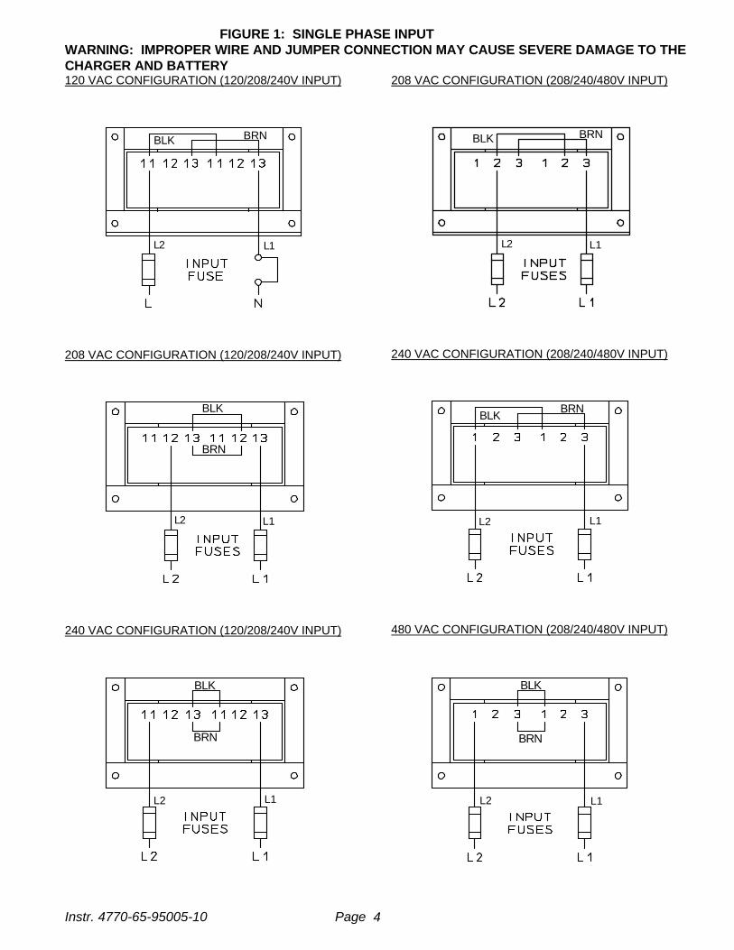
FIGURE 1: SINGLE PHASE INPUTWARNING: IMPROPER WIRE AND JUMPER CONNECTION MAY CAUSE SEVERE DAMAGE TO THECHARGER AND BATTERY
Instr. 4770-65-95005-10 Page 4
120 VAC CONFIGURATION (120/208/240V INPUT)
BLK BRN
208 VAC CONFIGURATION (120/208/240V INPUT)
BLK
BRN
240 VAC CONFIGURATION (120/208/240V INPUT)
BLK
BRN
208 VAC CONFIGURATION (208/240/480V INPUT)
BLK BRN
240 VAC CONFIGURATION (208/240/480V INPUT)
BLKBRN
480 VAC CONFIGURATION (208/240/480V INPUT)
BLK
BRN
L1L2 L1L2
L2 L1 L1L2
L1 L1L2L2

FIGURE 2: THREE PHASE INPUTWARNING: IMPROPER WIRE AND JUMPER CONNECTION MAY CAUSE SEVERE DAMAGE TO THECHARGER AND BATTERY
Instr. 4770-65-95005-10 Page 5
208VAC CONFIGURATION (208/240/480V INPUT)
240VAC CONFIGURATION (208/240/480V INPUT)
480VAC CONFIGURATION (208/240/480V INPUT)
L1 L1L2 L2L3
L3
L3 L3L1
L1L2 L2
L1 L1L2 L2L3
L3

FIGURE 3: THREE PHASE INPUTWARNING: IMPROPER WIRE AND JUMPER CONNECTION MAY CAUSE SEVERE DAMAGE TO THECHARGER AND BATTERY
Instr. 4770-65-95005-10 Page 6
208VAC CONFIGURATION (208/240/480V INPUT) (SCRFLX- XX-XXXXT1Z ONLY)
L2
L1 L1L2
L3
L3
240VAC CONFIGURATION (208/240/480V INPUT) (SCRFLX -XX-XXXXT1Z ONLY)
L1
L3
L1
L2
L2 L3
480VAC CONFIGURATION (208/240/480V INPUT) (SCRFLX -XX-XXXXT1Z ONLY)
L3L2
L1 L1L2 L3

Instr. 4770-65-95005-10 Page 7
5.3 AC VOLTAGE CONNECTIONS
To connect the input AC voltage, route the AC conduitthrough the knockout hole provided. Continue the ACwiring to fuseholder terminals L1 (N) and L2 (L) (singlephase input) or L1, L2, and L3 (three phase input),ensuring that the AC source phases match the phaserotation on the AC input. For proper connection, torquethe screws to approximately 25 inch-pounds.
5.4 GROUND CONNECTION
It is a requirement to ground the chassis while thecharger is connected to AC power. The charger comeswith a ground lug attached to the stud, clearly marked onthe chassis. To ensure good continuity keep the contactarea clean. The stud is designed for a 3/16” hardware.See gounding method shown below (Figure 4.).
WARNING: DO NOT OPERATE THE UNITWITHOUT PROPER GROUNDING. IMPROPERGROUNDING CAN RESULT IN THE RISK OF ANELECTRIC SHOCK AND ELIMINATESCHARGER WARRANTY.
CAUTION: USE MINIMUM 75°C WIRING. FORSUPPLY CONNECTIONS, GROUND CHARGERPROPERLY USING GROUNDING STUD (GND)PROVIDED. USE COPPER-CLAD ALUMINUM,ALUMINUM OR COPPER CONDUCTORS ONLY.
After electrical connection is completed, the charger isready for operation.
NOTE: The following applies to three phase chargersonly: if the charger indicates “FAC” or F3 upon start-up,it means that there is a low or high AC voltage (+35%)or AC phase missing. Refer to the TroubleshootingSection (Section 13, page 17) for more details.
FIGURE 4: GROUNDING METHOD
6.0 DC OUTPUT
The DC charging cable has a commonly used batteryplug or receptacle. The polarity of the charger plug mustbe the same as the battery connector. The BLACK DCcable must be connected to the battery negative (-), andthe RED DC cable must be connected to the batterypositive (+). The charger will not operate in a reversedpolarity condition.
The DC output fuse is a "fast-acting" fuse used toprotect the power semiconductors of a charger.
NOTE: Use only identical replacement fuses obtainable from your GNB service representative
Instr. 4770-65-95005-10 Page 8
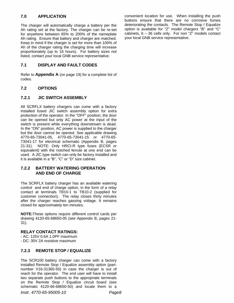
7.0 APPLICATION
The charger will automatically charge a battery per theAh rating set at the factory. The charger can be re-setfor anywhere between 65% to 200% of the nameplateAh rating. Ensure that battery and charger are matched.Keep in mind if the charger is set for more than 100% ofAh of the charger rating the charging time will increaseproportionately (up to 16 hours). For battery sizes notlisted, contact your local GNB service representative.
7.1 DISPLAY AND FAULT CODES
Refer to Appendix A (on page 19) for a complete list ofcodes.
7.2 OPTIONS
7.2.1 JIC SWITCH ASSEMBLY
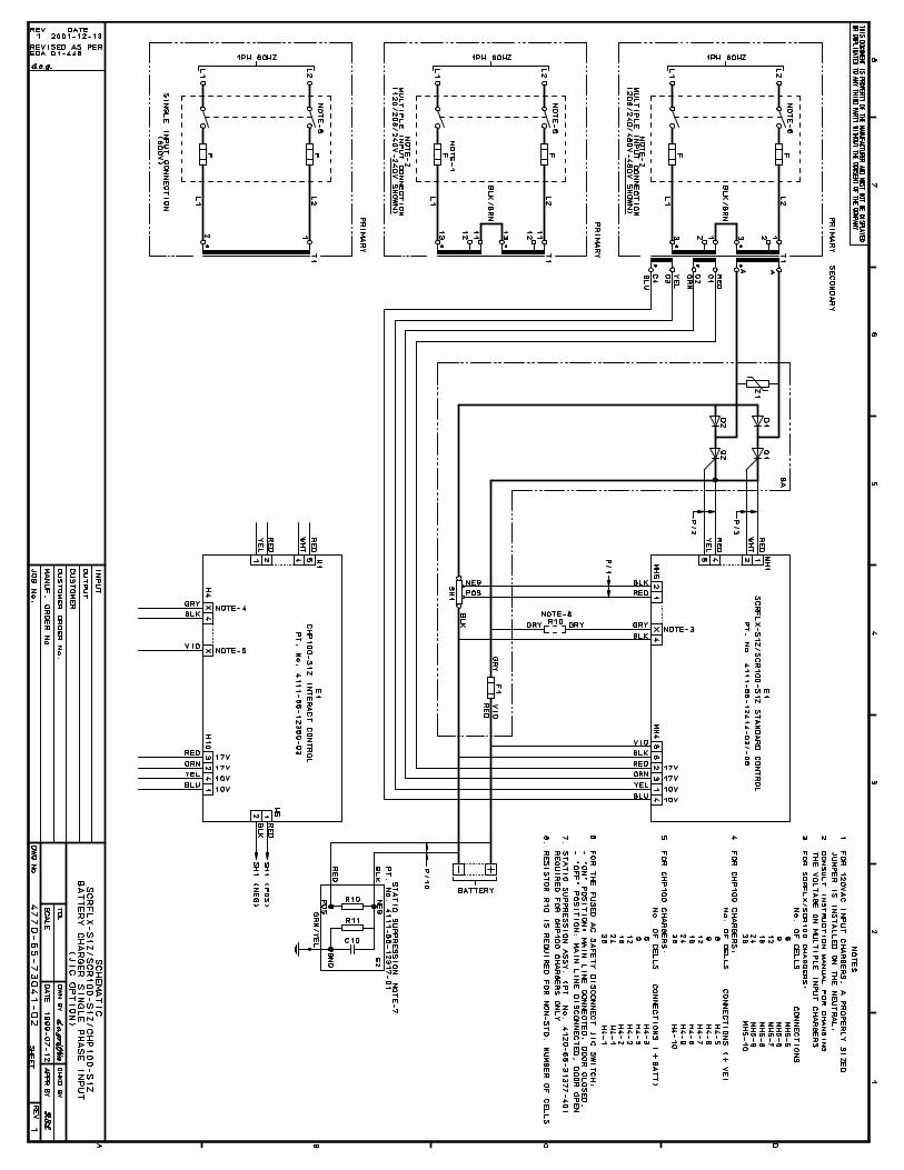
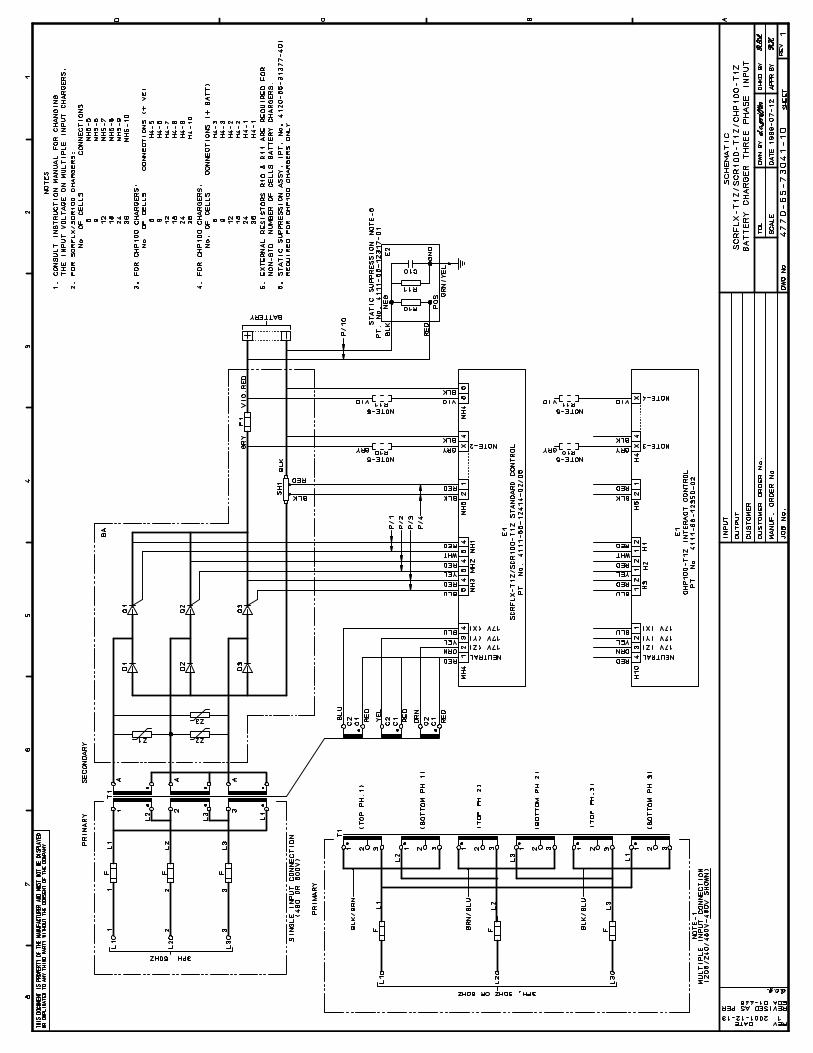
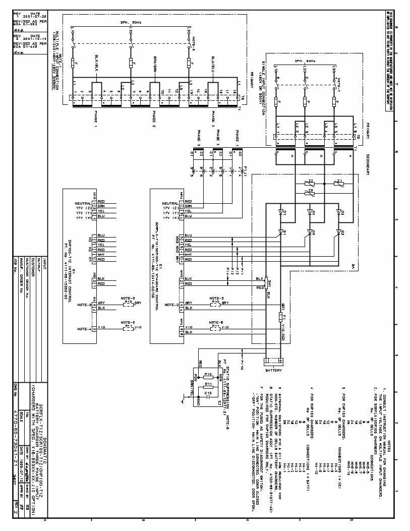
All SCRFLX battery chargers can come with a factoryinstalled fused JIC switch assembly option for extraprotection of the operator. In the "OFF" position, the doorcan be opened but only AC power at the input of theswitch is present while everything downstream is dead.In the "ON" position, AC power is supplied to the chargerbut the door cannot be opened. See applicable drawing4770-65-73041-05, 4770-65-73041-15 or 4770-65-73041-17 for electrical schematic (Appendix B, pages21-31). NOTE: Only HRCI-R type fuses (ECSR orequivalent) with the notched ferrule at one end can beused. A JIC type switch can only be factory installed andit is available in a “B”, “C” or “D” size cabinet.
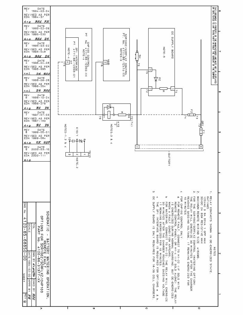
7.2.2 BATTERY WATERING OPERATION AND END OF CHARGE
The SCRFLX battery charger has an available wateringcontrol and end of charge option, in the form of a relaycontact at terminals TB10-1 to TB10-2 (supplied forcustomer connection). The relay closes thirty minutesafter the charger reaches gassing voltage. It remainsclosed for approximately ten minutes.
NOTE:These options require different control cards perdrawing 4120-65-68650-05 (see Appendix B, pages 21-31).
RELAY CONTACT RATINGS:- AC: 125V 0.6A 1.0PF maximum- DC: 30V 2A resistive maximum
7.2.3 REMOTE STOP / EQUALIZE
The SCR100 battery charger can come with a factoryinstalled Remote Stop / Equalize assembly option (part-number V16-31365-50) in case the charger is out ofreach for the operator. The end user will have to installtwo separate push buttons to the appropriate terminalson the Remote Stop / Equalize circuit board (seeschematic 4120-66-68650-50) and locate them to a
convenient location for use. When installing the pushbuttons ensure that there are no corrosive fumesdeteriorating the contacts. The Remote Stop / Equalizeoption is available for “Z” model chargers “B” and “C”cabinets, 6 – 36 cells only. For non “Z” models contactyour local GNB service representative.

TABLE 2 – SINGLE PHASE TECHNICAL DATA
Instr. 4770-65-95005-10 Page 9
STANDARD MODELSCRFLX-XX-XXXX-S1Z
DC AC AMPS @ AC VOLTS CABINET WEIGHT
AMPS 120 208 240 480 TYPE LBS KGS
SCRFLX-06-260S1Z AMPS 12 7 6 3 A 76 34.540
FUSE 15 10 8 4
SCRFLX-06-475S1Z AMPS 19 11 9.5 5 A 120 54.474
FUSE 25 15 12 7
(50 Hz) AMPS X X 9.5 X A 130 59.174
FUSE - - 12 -
SCRFLX-06-600S1Z AMPS 26 15 14 7 B 190 86.293
FUSE 35 20 20 10
(50 Hz) AMPS X X 13.5 X B 205 93.293
FUSE - - 20 -
SCRFLX-06-865S1Z AMPS C.F. 20 18 9 B 255 116134
FUSE - 25 25 12
SCRFLX-06-965S1Z AMPS C.F. 23 20 10 B 295 134150
FUSE - 30 25 15
SCRFLX-09-475S1Z AMPS 26 15 14 6.5 B 160 72.574
FUSE 35 20 20 10
SCRFLX-09-600S1Z AMPS C.F. 19 16 8 B 210 9593
FUSE - 25 20 10
SCRFLX-09-865S1Z AMPS C.F. 27 23.5 12 B 260 118134
FUSE - 35 30 15
SCRFLX-09-965S1Z AMPS C.F. 30 26 13 B 300 136150
FUSE - 40 35 20
SCRFLX-12-260S1Z AMPS 18.5 10.5 9 5 A 120 54.440
FUSE 25 15 12 7
(50 Hz) AMPS X X 9 X A 130 59.140
FUSE - - 12 -
SCRFLX-12-475S1Z AMPS C.F. 19.5 17 8.5 B 200 90.774
FUSE - 25 25 12
(50 Hz) AMPS X X 17 X B 212 96.474
FUSE - - 25 -
SCRFLX-12-600S1Z AMPS C.F. 25.5 22 11 B 225 10293
FUSE - 35 30 15
(50 Hz) AMPS X X 22 X B 235 10793
FUSE - - 30 -
SCRFLX-12-750S1Z AMPS C.F. 34 29 14.5 B 270 122116
FUSE - 45 40 20
SCRFLX-12-865S1Z AMPS C.F. 34 29 14.5 B 270 122134
FUSE - 45 40 20
SCRFLX-12-965S1Z AMPS C.F. 38 34 17 B 305 138150
FUSE - 50 45 25
SCRFLX-18-260S1Z AMPS C.F. 16 14 7 B 195 88.540
FUSE - 20 20 10
SCRFLX-18-475S1Z AMPS C.F. 30 26 14 B 240 10974
FUSE - 40 35 20
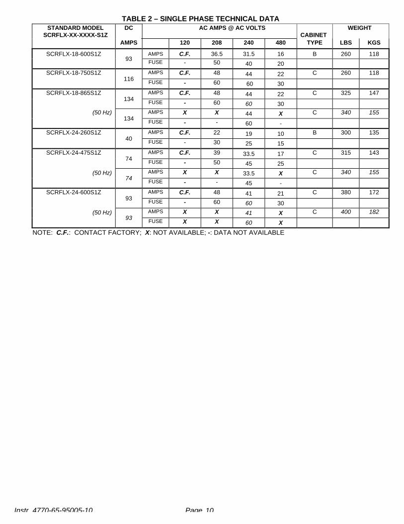
TABLE 2 – SINGLE PHASE TECHNICAL DATA
Instr. 4770-65-95005-10 Page 10
STANDARD MODELSCRFLX-XX-XXXX-S1Z
DC AC AMPS @ AC VOLTSCABINET
WEIGHT
AMPS 120 208 240 480 TYPE LBS KGS
SCRFLX-18-600S1Z AMPS C.F. 36.5 31.5 16 B 260 11893
FUSE - 50 40 20
SCRFLX-18-750S1Z AMPS C.F. 48 44 22 C 260 118116
FUSE - 60 60 30
SCRFLX-18-865S1Z AMPS C.F. 48 44 22 C 325 147134
FUSE - 60 60 30(50 Hz) AMPS X X 44 X C 340 155
134FUSE - - 60 -
SCRFLX-24-260S1Z AMPS C.F. 22 19 10 B 300 13540
FUSE - 30 25 15AMPS C.F. 39 33.5 17 C 315 143
74FUSE - 50 45 25AMPS X X 33.5 X C 340 155
SCRFLX-24-475S1Z
(50 Hz)74
FUSE - - 45 -AMPS C.F. 48 41 21 C 380 172
93FUSE - 60 60 30AMPS X X 41 X C 400 182
SCRFLX-24-600S1Z
(50 Hz)93
FUSE X X 60 X
NOTE: C.F.: CONTACT FACTORY; X: NOT AVAILABLE; -: DATA NOT AVAILABLE

TABLE 3 – THREE PHASE TECHNICAL DATA
Instr. 4770-65-95005-10 Page 11
AC AMPS @ AC VOLTS
STANDARD MODEL DC 60Hz 50Hz CABINET WEIGHT
SCRFLX-XX-XXXX-T1Z AMPS 208 240 480 380 415 TYPE LBS KGS
SCRFLX-06-475T1Z AMPS 5 4.5 2.2 C.F. C.F. B 170 77.174
FUSE 7 6 3 - -
SCRFLX-06-600T1Z AMPS 7 6 3.5 C.F. 3.5 B 190 86.293 FUSE 10 8 5 - 5
AMPS 9 8 4 C.F. C.F. B 220 99.8SCRFLX-06-750T1Z116
FUSE 12 12 6 - -
SCRFLX-06-865T1Z AMPS 10 9 5 C.F. C.F. B 220 99.8134
FUSE 15 12 7 - -
SCRFLX-06-965T1Z AMPS 11 10 5 C.F. C.F. B 235 107150
FUSE 15 15 7 - -
SCRFLX-06-1050T1Z AMPS 12 11 5.5 C.F. C.F. B 245 111163
FUSE 15 15 8 - -
AMPS 12.7 11 5 C.F. C.F. C 260 118SCRFLX-06-1200T1Z186
FUSE 20 15 7 - -
SCRFLX-06-1450T1Z AMPS 15 14 7 C.F. C.F. C 290 132225
FUSE 20 20 10 - -
SCRFLX-09-600T1Z AMPS 12 10 5 C.F. C.F. B 220 99.893
FUSE 15 15 7 - -
SCRFLX-12-475T1Z AMPS 9 8 4 5.5 5 B 215 97.674
FUSE 12 12 6 8 7SCRFLX-12-600T1Z AMPS 11.5 10 5 7 7 B 220 100
93FUSE 15 15 7 10 10
SCRFLX-12-750T1Z AMPS 15 14 7 9.2 9 B 250 113.5116FUSE 20 20 10 12 12
SCRFLX-12-865T1Z AMPS 16 14 7 10 9 B 255 116134
FUSE 20 20 10 15 12
SCRFLX-12-965T1Z AMPS 21 18 9 C.F. C.F. C 260 118150
FUSE 30 25 12 - -
SCRFLX-12-1050T1Z AMPS 22 19 9.5 12 C.F. C 270 122163
FUSE 30 25 12 15
SCRFLX-12-1200T1Z 186 AMPS 26 22 11 C.F. C.F. C 298 135FUSE 35 30 15 - -
SCRFLX-12-1450T1Z 225 AMPS 30 26 14 C.F. C.F. C 310 141FUSE 40 35 20 - -
SCRFLX-18-260T1Z 40 AMPS 9 8 4 C.F. C.F. B 215 98FUSE 12 10 6 - -
SCRFLX-18-475T1Z 74 AMPS 14 11 5.5 C.F. 8 B 255 116FUSE 20 15 8 - 12
AMPS 16 14 7 C.F. 10 B / C* 300 136SCRFLX-18-600T1Z93
FUSE 20 20 10 - 15
SCRFLX-18-750T1Z 116 AMPS 20 18 9 16 15 B / C* 310 141FUSE 30 25 12 20 20
SCRFLX-18-865T1Z 134 AMPS 24 21 10.5 16 15 C 325 148FUSE 35 30 15 20 20
SCRFLX-18-965T1Z 150 AMPS 26 22 11 18 17 C 340 155FUSE 35 30 15 25 25

TABLE 3 – THREE PHASE TECHNICAL DATA
Instr. 4770-65-95005-10 Page 12
AC AMPS @ AC VOLTS
STANDARD MODEL DC 60Hz 50Hz CABINET WEIGHT
SCRFLX-XX-XXXX-T1Z AMPS 208 240 480 380 415 TYPE LBS KGS
SCRFLX-18-1050T1Z AMPS 28 24 12 19 17.5 C 380 163163
FUSE 40 35 15 25 25
SCRFLX-18-1200T1Z AMPS 37 32 16 26 C.F. C 410 186186 FUSE 50 45 20 35 -
AMPS 47.5 41 21 27 26 C 450 204SCRFLX-18-1450T1Z225
FUSE 60 60 30 35 35
SCRFLX-18-1700T1Z AMPS 48 44 22 C.F. C.F. D 550 250264
FUSE 60 60 30 - -
SCRFLX-24-475T1Z AMPS 17 15 7.5 C.F. 10 B / C* 290 13274
FUSE 25 20 10 - 15
SCRFLX-24-600T1Z AMPS 21 18 9.5 15 12 C 320 14593
FUSE 30 25 12 20 15
AMPS 28 24 12 18 15 C 345 157SCRFLX-24-750T1Z116
FUSE 40 35 15 25 20
SCRFLX-24-865T1Z AMPS 31 27 14 18 17.2 C 380 173134
FUSE 45 40 20 25 25
SCRFLX-24-965T1Z AMPS 40 36 18 C.F. 20 C 400 182150
FUSE 60 50 25 - 30
SCRFLX-24-1050T1Z AMPS 44 38 18.5 24 22 C 425 193163
FUSE 60 50 25 35 30
SCRFLX-24-1200T1Z AMPS 48 46 23 28 C.F. C 440 200186
FUSE 60 60 30 40 -
SCRFLX-24-1450T1Z AMPS C.F. C.F. 27 27 22 C 490 222225
FUSE - - 35 35 30
SCRFLX-24-1700T1Z AMPS C.F. C.F. 31 31 25 D 525 239264
FUSE - - 40 40 35
SCRFLX-36-475T1Z AMPS 34 29 14.5 C.F. C.F. C 330 15074
FUSE 45 40 20 - -
SCRFLX-36-600T1Z AMPS 41 35 18 21 20.5 C 420 19093
FUSE 60 50 25 35 30
SCRFLX-36-750T1Z 116 AMPS 46 40 20 C.F. 27 C 460 209FUSE 60 60 30 - 35
SCRFLX-36-865-T1Z 134 AMPS C.F. 46.5 23 C.F. 27 C 480 218FUSE - 60 30 - 35
SCRFLX-36-965-T1Z 150 AMPS C.F. C.F. 27 C.F. 29.4 C 500 227FUSE - - 40 - 40
SCRFLX-36-1450-T1Z 225 AMPS C.F. C.F. 37 C.F. 42 D 550 250FUSE - - 50 - 60
AMPS 39 34 17 C.F. 19.5 C 450 204SCRFLX-40-475-T1Z74
FUSE 50 45 25 - 25SCRFLX-40-1200-T1Z 186 AMPS C.F. C.F. 33 C.F. C.F. D 500 227
FUSE - - 45 - -
SCRFLX-48-600-T1Z 93 AMPS 48 42 21 C.F. C.F. D 550 250FUSE 60 60 30 - -
SCRFLX-48-865-T1Z 134 AMPS C.F. C.F. C.F. C.F. C.F. D 600 272FUSE - - - - -
NOTE: C.F.: CONTACT FACTORY; X: NOT AVAILABLE -: DATA NOT AVAILABLE; *: 50Hz MODELS ARE IN A “C” CABINET

Instr. 4770-65-95005-10 Page 13
8.0 CABINET OUTLINE/DIMENSIONS FOR –Z MODEL CHARGERS ONLY
CABINET DIM. A DIM. B DIM. CA 15.10” 20.65” 12.75”B 22.70” 26.65” 22.25”C 32.10” 26.65” 22.25”D 24.30” 42.00” 23.65”
D (Mining) 24.30” 42.00” 23.65”E (Mining) 24.30” 59.00” 31.50”
NOTE: Mining chargers are equipped with a drip cap and four lifting eyebolts for sling lifting. Add an additional5.000” to the height. (DIM.B)
Instr. 4770-65-95005-10 Page 14
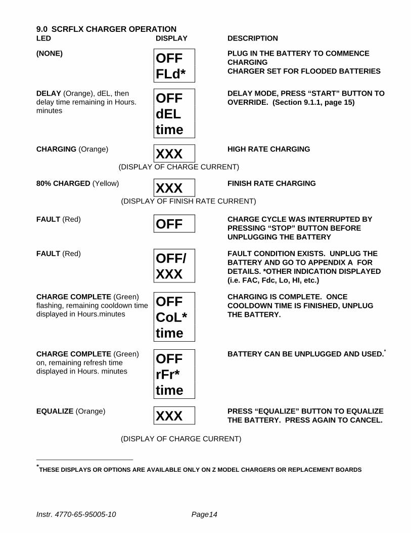
9.0 SCRFLX CHARGER OPERATIONLED DISPLAY DESCRIPTION
(NONE) OFFFLd*
PLUG IN THE BATTERY TO COMMENCECHARGINGCHARGER SET FOR FLOODED BATTERIES
DELAY (Orange), dEL, thendelay time remaining in Hours.minutes
OFFdELtime
DELAY MODE, PRESS “START” BUTTON TOOVERRIDE. (Section 9.1.1, page 15)
CHARGING (Orange) XXX HIGH RATE CHARGING
(DISPLAY OF CHARGE CURRENT)
80% CHARGED (Yellow) XXX FINISH RATE CHARGING
(DISPLAY OF FINISH RATE CURRENT)
FAULT (Red) OFF CHARGE CYCLE WAS INTERRUPTED BYPRESSING “STOP” BUTTON BEFOREUNPLUGGING THE BATTERY
FAULT (Red) OFF/XXX
FAULT CONDITION EXISTS. UNPLUG THEBATTERY AND GO TO APPENDIX A FORDETAILS. *OTHER INDICATION DISPLAYED(i.e. FAC, Fdc, Lo, HI, etc.)
CHARGE COMPLETE (Green)flashing, remaining cooldown timedisplayed in Hours.minutes
OFFCoL*time
CHARGING IS COMPLETE. ONCECOOLDOWN TIME IS FINISHED, UNPLUGTHE BATTERY.
CHARGE COMPLETE (Green)on, remaining refresh timedisplayed in Hours. minutes
OFFrFr*time
BATTERY CAN BE UNPLUGGED AND USED.*
EQUALIZE (Orange) XXX PRESS “EQUALIZE” BUTTON TO EQUALIZETHE BATTERY. PRESS AGAIN TO CANCEL.
(DISPLAY OF CHARGE CURRENT)
∗∗THESE DISPLAYS OR OPTIONS ARE AVAILABLE ONLY ON Z MODEL CHARGERS OR REPLACEMENT BOARDS
Instr. 4770-65-95005-10 Page 15
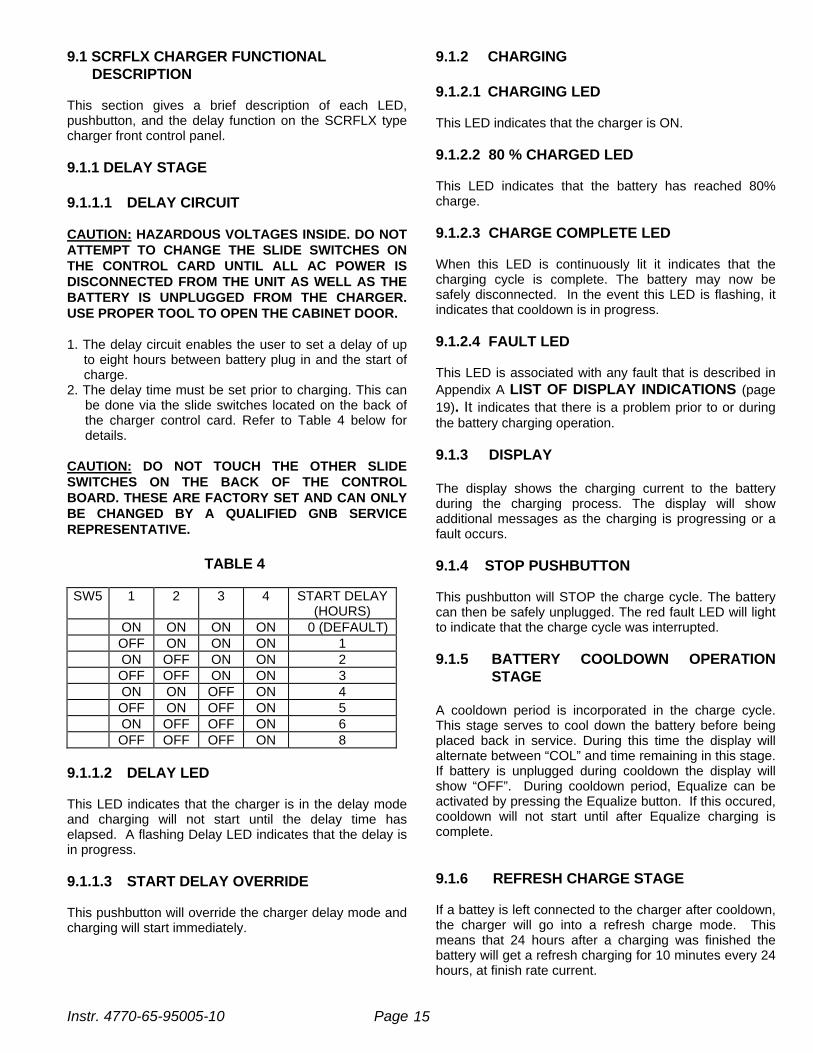
9.1 SCRFLX CHARGER FUNCTIONAL DESCRIPTION
This section gives a brief description of each LED,pushbutton, and the delay function on the SCRFLX typecharger front control panel.
9.1.1 DELAY STAGE
9.1.1.1 DELAY CIRCUIT
CAUTION: HAZARDOUS VOLTAGES INSIDE. DO NOTATTEMPT TO CHANGE THE SLIDE SWITCHES ONTHE CONTROL CARD UNTIL ALL AC POWER ISDISCONNECTED FROM THE UNIT AS WELL AS THEBATTERY IS UNPLUGGED FROM THE CHARGER.USE PROPER TOOL TO OPEN THE CABINET DOOR.
1. The delay circuit enables the user to set a delay of upto eight hours between battery plug in and the start ofcharge.
2. The delay time must be set prior to charging. This canbe done via the slide switches located on the back ofthe charger control card. Refer to Table 4 below fordetails.
CAUTION: DO NOT TOUCH THE OTHER SLIDESWITCHES ON THE BACK OF THE CONTROLBOARD. THESE ARE FACTORY SET AND CAN ONLYBE CHANGED BY A QUALIFIED GNB SERVICEREPRESENTATIVE.
TABLE 4
SW5 1 2 3 4 START DELAY(HOURS)
ON ON ON ON 0 (DEFAULT)OFF ON ON ON 1ON OFF ON ON 2OFF OFF ON ON 3ON ON OFF ON 4OFF ON OFF ON 5ON OFF OFF ON 6OFF OFF OFF ON 8
9.1.1.2 DELAY LED
This LED indicates that the charger is in the delay modeand charging will not start until the delay time haselapsed. A flashing Delay LED indicates that the delay isin progress.
9.1.1.3 START DELAY OVERRIDE
This pushbutton will override the charger delay mode andcharging will start immediately.
9.1.2 CHARGING
9.1.2.1 CHARGING LED
This LED indicates that the charger is ON.
9.1.2.2 80 % CHARGED LED
This LED indicates that the battery has reached 80%charge.
9.1.2.3 CHARGE COMPLETE LED
When this LED is continuously lit it indicates that thecharging cycle is complete. The battery may now besafely disconnected. In the event this LED is flashing, itindicates that cooldown is in progress.
9.1.2.4 FAULT LED
This LED is associated with any fault that is described inAppendix A LIST OF DISPLAY INDICATIONS (page19). It indicates that there is a problem prior to or duringthe battery charging operation.
9.1.3 DISPLAY
The display shows the charging current to the batteryduring the charging process. The display will showadditional messages as the charging is progressing or afault occurs.
9.1.4 STOP PUSHBUTTON
This pushbutton will STOP the charge cycle. The batterycan then be safely unplugged. The red fault LED will lightto indicate that the charge cycle was interrupted.
9.1.5 BATTERY COOLDOWN OPERATIONSTAGE
A cooldown period is incorporated in the charge cycle.This stage serves to cool down the battery before beingplaced back in service. During this time the display willalternate between “COL” and time remaining in this stage.If battery is unplugged during cooldown the display willshow “OFF”. During cooldown period, Equalize can beactivated by pressing the Equalize button. If this occured,cooldown will not start until after Equalize charging iscomplete.
9.1.6 REFRESH CHARGE STAGE
If a battey is left connected to the charger after cooldown,the charger will go into a refresh charge mode. Thismeans that 24 hours after a charging was finished thebattery will get a refresh charging for 10 minutes every 24hours, at finish rate current.

Instr. 4770-65-95005-10 Page 16
9.1.7 EQUALIZE STAGE
9.1.7.1 EQUALIZE PUSHBUTTON
This pushbutton when pressed will extend the chargecycle by 3.5 hours in the equalize mode after the finishrate time has expired. If pressed a second time, it willcancel the equalize charge mode.
CAUTION: DO NOT EQUALIZE MORE OFTEN THANREQUIRED BY THE CONDITION OF THE BATTERY,AS SPECIFIED IN THE BATTERY MAINTENANCEINSTRUCTIONS. EXCESSIVE EQUALIZING MAYDAMAGE THE BATTERY.
9.1.7.2 EQUALIZE LED
This LED indicates that the equalize mode has beenselected. A flashing equalize LED indicates that it is inprocess.
10.0 CHARGE TIME
The amount of time a battery charges will vary dependingon the depth of discharge (DOD). Once the battery hasreached 80% charge, the cycle will be terminated in 3.5hours (in case of an 8 hour charge time) or less ifterminated by dv/dt. Normal charge cycles will averageabout 8 hours total.
11.0 AC POWER FAILURE
If the AC power fails during a charge cycle the charger willresume operation in progress as soon as the AC power isrestored.
12.0 MAINTENANCE
The charger requires minimum maintenance. ENSURETHE CHASSIS IS SECURELY GROUNDED per thelocal/federal Electrical Code. Do not allow excessive dustto accumulate on the components inside. Blow out withclean compressed air when necessary.
The AC input and DC output of the charger are fused andshould these fuses fail, the cause of the failure must bedetermined and corrected before the fuse(s) is (are)replaced. Never replace the fuse(s) with one of a highercapacity than the one originally fitted (see Tables 2 and 3pages 9-12).
Instr. 4770-65-95005-10 Page 17
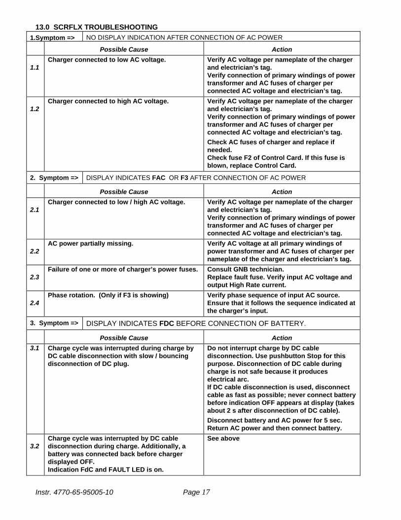
13.0 SCRFLX TROUBLESHOOTING1.Symptom => NO DISPLAY INDICATION AFTER CONNECTION OF AC POWER
Possible Cause Action
1.1Charger connected to low AC voltage. Verify AC voltage per nameplate of the charger
and electrician’s tag.Verify connection of primary windings of powertransformer and AC fuses of charger perconnected AC voltage and electrician’s tag.
1.2Charger connected to high AC voltage. Verify AC voltage per nameplate of the charger
and electrician’s tag.Verify connection of primary windings of powertransformer and AC fuses of charger perconnected AC voltage and electrician’s tag.
Check AC fuses of charger and replace ifneeded.Check fuse F2 of Control Card. If this fuse isblown, replace Control Card.
2. Symptom => DISPLAY INDICATES FAC OR F3 AFTER CONNECTION OF AC POWER
Possible Cause Action
2.1Charger connected to low / high AC voltage. Verify AC voltage per nameplate of the charger
and electrician’s tag.Verify connection of primary windings of powertransformer and AC fuses of charger perconnected AC voltage and electrician’s tag.
2.2AC power partially missing. Verify AC voltage at all primary windings of
power transformer and AC fuses of charger pernameplate of the charger and electrician’s tag.
2.3Failure of one or more of charger’s power fuses. Consult GNB technician.
Replace fault fuse. Verify input AC voltage andoutput High Rate current.
2.4Phase rotation. (Only if F3 is showing) Verify phase sequence of input AC source.
Ensure that it follows the sequence indicated atthe charger’s input.
3. Symptom => DISPLAY INDICATES FDC BEFORE CONNECTION OF BATTERY.
Possible Cause Action
3.1 Charge cycle was interrupted during charge byDC cable disconnection with slow / bouncingdisconnection of DC plug.
Do not interrupt charge by DC cabledisconnection. Use pushbutton Stop for thispurpose. Disconnection of DC cable duringcharge is not safe because it produceselectrical arc.If DC cable disconnection is used, disconnectcable as fast as possible; never connect batterybefore indication OFF appears at display (takesabout 2 s after disconnection of DC cable).
Disconnect battery and AC power for 5 sec.Return AC power and then connect battery.
3.2Charge cycle was interrupted by DC cabledisconnection during charge. Additionally, abattery was connected back before chargerdisplayed OFF.Indication FdC and FAULT LED is on.
See above

Instr. 4770-65-95005-10 Page 18
3.3Charger’s DC fuse blown.Indication FdC and FAULT LED is on.
Disconnect battery and AC power.Consult GNB technician.
4. Symptom => CHARGING LED DOES NOT LIGHT ON AFTER BATTERY CONNECTION
Possible Cause Action
4.1 Connection between charger and battery open. Repair or clean battery lugs. Repair and/or change charger and /or batteryDC cables and contacts of DC connectors.
4.2 Battery with wrong number of cells connected toa charger.Indication LO/rEJ or HI/rEJ and FAULT LED ison.
Replace with correct battery.
4.3 Battery voltage too low.Indication LO/rEJ and FAULT LED is on.
Consult GNB technician.
4.4 A charger operates at Delay.Indication dEL/Remaining Delay Time, LEDDelay is on.
Wait till end of Delay or press pushbutton Start.
5. Symptom => DISPLAY INDICATES FCC OR F2 AT THE END OF CHARGE CYCLE
Possible Cause Action
5.1 Battery failed to reach gassing voltage. Consult GNB technician.Check matching of charger and battery: Ah,type.
6. Symptom => DISPLAY INDICATES FAC OR F3 DURING CHARGE CYCLE
Possible Cause Action
6.1Complete or partial loss of AC power. Wait until AC returns: charger will automatically
complete charge cycle.If needed, battery may be disconnected duringAC failure.
6.2Failure of one or more of charger’s power fuses. Consult GNB technician.
Replace fault fuse. Verify input AC voltage andoutput High Rate current.
6.3Failure of Control Card. Consult GNB technician.
Verify input AC voltage. Replace fault ControlCard.
7. Symptom => DISPLAY INDICATES OFF (ONLY) AND FAULT LED IS ON
Possible Cause Action
7.1Pushbutton Stop interrupted charge cycle. Use pushbutton Stop only when you want
interrupt charge cycle or disconnect battery.Charger will start automatically afterconnection of next battery.
8. Symptom => DISPLAY INDICATES FCS AFTER CONNECTION ON BATTERY
Possible Cause Action
8.1 Charger control board was set improperly. Priorto connection the display indicated OFF/CHP notOFF/Fld
Call your local GNB representative forprocedure to change this setting.

Instr. 4770-65-95005-10 Page 19
APPENDIX A: SCRFLX BATTERY CHARGERS. LIST OF DISPLAY INDICATIONS.
Indication Abbreviation Interpretation
1.00 1 hour delay set Delay before charge starts2.00 2 hour delay set Delay before charge starts3.00 3 hour delay set Delay before charge starts4.00 4 hour delay set Delay before charge starts5.00 5 hour delay set Delay before charge starts6.00 6 hour delay set Delay before charge starts8.00 8 hour delay set Delay before charge starts
CHP CHamPion Control board is set to 2.55VPC not 2.70VPC.
COL COoL Down Charger operates at Cool Down Stage
dEL dELay Delay set or Charger operates at Delay Stage
End End Charge Cycle complete
FAC or F3 Failure of AC power Failure of mainsFCA Failure of DC CAble
disconnectionDC cable disconnected from the battery during thecharge
FCCorF2
Failure of Charge Cycle Battery failed to reach Gassing Voltage (Stage 2)orBattery failed to reach End Voltage (Stage 3 of OPC)
FCd Failure of Cool down Battery unplugged during Cool Down StageFdC Failure of dC Fuse Output DC Fuse FailureFFF F…Fatal Failure Fatal Failure of the charger (Overvoltage or
Overcurrent protection or multifunction of Start Stopsignal)
FOC Failure of Overall Chargetimer
Overall charge cycle timer protection
FLd FLooded Charger set for Flooded batteries
HI High Voltage Rejection Battery connected has voltage more than 2.25VPC
LO LOw Voltage Rejection Battery connected has voltage less than 1.70VPC
OFF OFF Charger is OFF
rEJ rEJect Battery connected has voltage too low or too highorBattery failed to reach 1.70VPC after 5 min ofcharge
rFr reFreshing Stage Charger operates at Refreshing Stage

Instr. 4770-65-95005-10 Page 20

Instr. 4770-65-95005-10 Page 21
APPENDIX B: ELECTRICAL SCHEMATIC DRAWINGSPages 21-31


SALES • SERVICE • RECYCLING
TOLL FREE 1-888-563-6300
Champion® is a registered trademark of Federal-Mogul Corporation
Exide TechnologiesChloride Motive PowerP.O. Box 1, Salford RoadOver Hulton, Bolton BL5 1DDUnited KingdomTel: 44.1204.661.230Fax: 44.1204.652.100
GNB Industrial PowerMotive Power8301 Keele StreetMaple, OntarioCanada L6A 1T2Tel: 905.669.9326Fax: 905.669.7688
REV 09/02
GNB Industrial PowerMotive Power829 Parkview BoulevardLombard, IL 60148-3249U.S.A.Tel: 877.GNB.INFOFax: 630.691.7869
Printed on recycled paper A
www.gnb.com


