Installation, Operation and Maintenance Manual Caleffi Solar Hot Water Heater Models: NAS30020, NAS30020Plus, NAS30040, NAS30040Plus, NAS30042, NAS30042Plus, NAS30060, NAS30060Plus, NAS30062, NAS30062Plus Caleffi North America, Inc. 3883 W. Milwaukee Road Milwaukee, Wisconsin 53208 NA10105
Transcript
Installation, Operationand Maintenance Manual
Caleffi Solar Hot Water HeaterModels: NAS30020, NAS30020Plus, NAS30040, NAS30040Plus,
Installation, Operation and Maintenance Manual - Caleffi Solar Hot Water Heater 3
1PREFACEThank you for buying a Caleffi solar hot water heater. Established in 1961, Caleffi is a global leader in hydronicheating equipment manufacturing. With North American manufacturing headquarters in Milwaukee, Caleffisolar thermal equipment is sold by leading solar, heating, plumbing, and building contractors across theUnited States and Canada.
The Solar Rating & Certification Corporation (SRCC) Standard OG-300 (Operating Guidelines and MinimumStandards for Certifying Solar water Heating Systems) certification is a requirement by several governmentaland utility entities to qualify the end user for various financial benefits such as tax credits, rebates and loans.
This Caleffi solar energy system design has undergone an extensive performance review by the SRCC and has been certified to Standard OG-300. When properly installed and maintained per this manual, the solar system meets the minimum standards established by the SRCC. This certification does not implyendorsement or warranty of this product by SRCC.
The installation of this system is intended to be performed by properly licensed and experienced professionalcontractors in accordance with SRCC Standard OG-300, and must conform to applicable federal, state andlocal regulations, codes, ordinances and standards governing the installation of solar water heating systems.
This system comes with a pre-mixed anti-freeze heat transfer solution fluid (HTF) containing non-toxic propylene glycol and de-ionized water. Unauthorized fluid substitutions can result in a threat to health, welfare and safety and can result in pipe freezing and equipment damage. All component warranties expressor implied, are voided if the HTF is not maintained in accordance with instructions.
When properly installed and maintained, this system will protect against freeze damage to temperatures aslow as -75°F (-59°C). The lowest recorded temperature in the Continental US is -70°F (Montana 1954).
Solar water heating systems are climate and site specific appliances. System performance varies as a function of household hot water use, including daily showers and baths, laundry and kitchen uses, localground water temperatures and ambient air temperatures, your home’s roof pitch and orientation and, ofcourse, the seasonal intensity of solar radiation. These variables determine how much energy and money your Caleffi system will save. When sized properly, your solar thermal hot water heater can produce between50% and 80% of your hot water demand on an annual basis.
2SUPPLEMENTAL INSTRUCTIONSIn addition to this manual, the system comes with three supplemental documents: • Installation, commissioning and servicing instructions for NAS200 Series SolarCon solar water heater tank
(in a bag taped to side of the tank),• iSolar controller manual (in the controller packaging),• Installation and commissioning instructions for 255 series and 256 series Pumping Station (in the pumping
station packaging)
It is important to read through these documents before beginning installation and operation.
3SYSTEM OPERATING PRINCIPLESimply stated, when the sun is shining, heat energy is absorbed by the solar collector’s absorber plate andtransferred to the HTF circulating through the solar collector. The system pump circulates this heated fluidthrough the collector piping and integral tank heat exchanger located in the bottom of the storage tank. As the HTF passes through the heat exchanger the heat in the fluid is transferred by conduction to thepotable water in the solar storage tank. As this process is continuously repeated, the water temperature in the solar storage tank rises.
4INSTALLATION OPTIONS FOR BACK-UP HEATThough many installations will produce 100% of hot water requirements by solar energy on sunny mid-yeardays, on cloudy days and fall/winter days, back-up heat is required.
Here are the 4 most common options used for back-up heat:
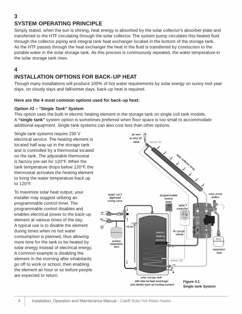
Option #1 – “Single Tank” SystemThis option uses the built-in electric heating element in the storage tank on single coil tank models. A “single tank” system option is sometimes preferred when floor space is too small to accommodate additional equipment. Single tank systems can also cost less than other options.
Single tank systems require 230 V electrical service. The heating element islocated half way up in the storage tankand is controlled by a thermostat locatedon the tank. The adjustable thermostat is factory pre-set for 120°F. When the tank temperature drops below 120°F, thethermostat activates the heating elementto bring the water temperature back upto 120°F.
To maximize solar heat output, your installer may suggest utilizing an programmable control timer. The programmable control disables and enables electrical power to the back-upelement at various times of the day. A typical use is to disable the elementduring times when no hot water consumption is planned, thus allowingmore time for the tank to be heated bysolar energy instead of electrical energy.A common example is disabling the element in the morning after inhabitantsgo off to work or school, then enablingthe element an hour or so before peopleare expected to return.
4 Installation, Operation and Maintenance Manual - Caleffi Solar Hot Water Heater
Figure 4.1Single tank System
5Installation, Operation and Maintenance Manual - Caleffi Solar Hot Water Heater
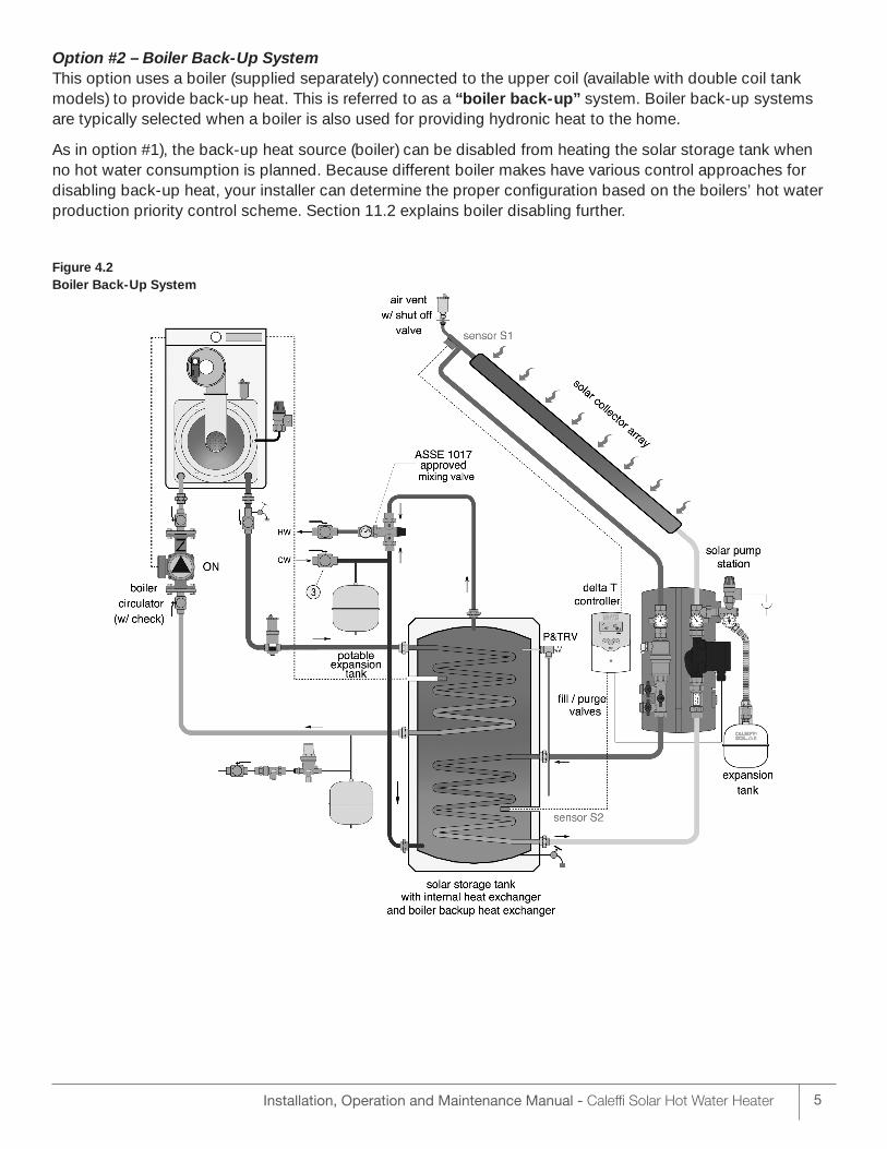
Option #2 – Boiler Back-Up SystemThis option uses a boiler (supplied separately) connected to the upper coil (available with double coil tankmodels) to provide back-up heat. This is referred to as a “boiler back-up” system. Boiler back-up systemsare typically selected when a boiler is also used for providing hydronic heat to the home.
As in option #1), the back-up heat source (boiler) can be disabled from heating the solar storage tank when no hot water consumption is planned. Because different boiler makes have various control approaches fordisabling back-up heat, your installer can determine the proper configuration based on the boilers’ hot waterproduction priority control scheme. Section 11.2 explains boiler disabling further.
Figure 4.2Boiler Back-Up System
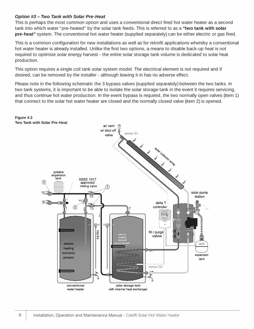
Option #3 – Two Tank with Solar Pre-HeatThis is perhaps the most common option and uses a conventional direct fired hot water heater as a secondtank into which water “pre-heated” by the solar tank feeds. This is referred to as a “two tank with solar pre-heat” system. The conventional hot water heater (supplied separately) can be either electric or gas fired.
This is a common configuration for new installations as well as for retrofit applications whereby a conventionalhot water heater is already installed. Unlike the first two options, a means to disable back-up heat is not required to optimize solar energy harvest - the entire solar storage tank volume is dedicated to solar heat production.
This option requires a single coil tank solar system model. The electrical element is not required and if desired, can be removed by the installer - although leaving it in has no adverse effect.
Please note in the following schematic the 3 bypass valves (supplied separately) between the two tanks. Intwo tank systems, it is important to be able to isolate the solar storage tank in the event it requires servicing,and thus continue hot water production. In the event bypass is required, the two normally open valves (item 1)that connect to the solar hot water heater are closed and the normally closed valve (item 2) is opened.
Figure 4.3Two Tank with Solar Pre-Heat
6 Installation, Operation and Maintenance Manual - Caleffi Solar Hot Water Heater
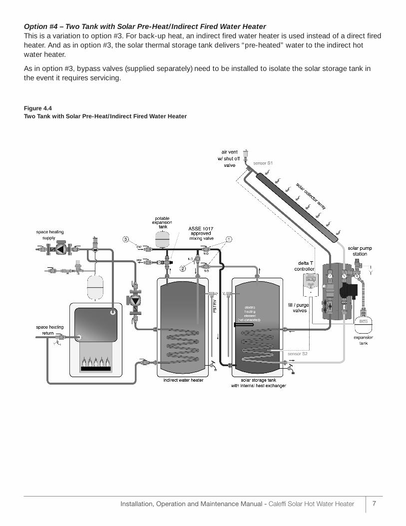
Option #4 – Two Tank with Solar Pre-Heat/Indirect Fired Water Heater This is a variation to option #3. For back-up heat, an indirect fired water heater is used instead of a direct firedheater. And as in option #3, the solar thermal storage tank delivers “pre-heated” water to the indirect hotwater heater.
As in option #3, bypass valves (supplied separately) need to be installed to isolate the solar storage tank inthe event it requires servicing.
Figure 4.4Two Tank with Solar Pre-Heat/Indirect Fired Water Heater
7Installation, Operation and Maintenance Manual - Caleffi Solar Hot Water Heater
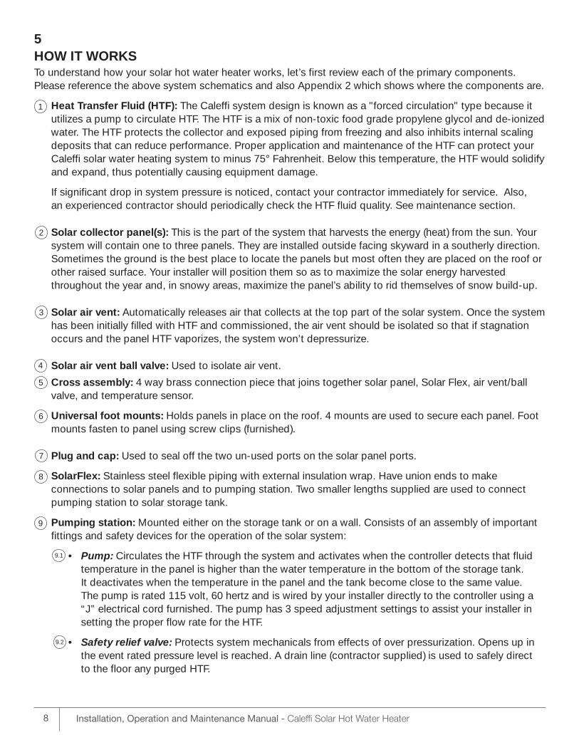
5HOW IT WORKSTo understand how your solar hot water heater works, let’s first review each of the primary components.Please reference the above system schematics and also Appendix 2 which shows where the components are.
Heat Transfer Fluid (HTF): The Caleffi system design is known as a "forced circulation" type because itutilizes a pump to circulate HTF. The HTF is a mix of non-toxic food grade propylene glycol and de-ionizedwater. The HTF protects the collector and exposed piping from freezing and also inhibits internal scalingdeposits that can reduce performance. Proper application and maintenance of the HTF can protect yourCaleffi solar water heating system to minus 75° Fahrenheit. Below this temperature, the HTF would solidifyand expand, thus potentially causing equipment damage.
If significant drop in system pressure is noticed, contact your contractor immediately for service. Also, an experienced contractor should periodically check the HTF fluid quality. See maintenance section.
Solar collector panel(s): This is the part of the system that harvests the energy (heat) from the sun. Yoursystem will contain one to three panels. They are installed outside facing skyward in a southerly direction.Sometimes the ground is the best place to locate the panels but most often they are placed on the roof orother raised surface. Your installer will position them so as to maximize the solar energy harvestedthroughout the year and, in snowy areas, maximize the panel’s ability to rid themselves of snow build-up.
Solar air vent: Automatically releases air that collects at the top part of the solar system. Once the systemhas been initially filled with HTF and commissioned, the air vent should be isolated so that if stagnationoccurs and the panel HTF vaporizes, the system won’t depressurize.
Solar air vent ball valve: Used to isolate air vent.
Cross assembly: 4 way brass connection piece that joins together solar panel, Solar Flex, air vent/ballvalve, and temperature sensor.
Universal foot mounts: Holds panels in place on the roof. 4 mounts are used to secure each panel. Footmounts fasten to panel using screw clips (furnished).
Plug and cap: Used to seal off the two un-used ports on the solar panel ports.
SolarFlex: Stainless steel flexible piping with external insulation wrap. Have union ends to make connections to solar panels and to pumping station. Two smaller lengths supplied are used to connectpumping station to solar storage tank.
Pumping station: Mounted either on the storage tank or on a wall. Consists of an assembly of importantfittings and safety devices for the operation of the solar system:
• Pump: Circulates the HTF through the system and activates when the controller detects that fluid temperature in the panel is higher than the water temperature in the bottom of the storage tank. It deactivates when the temperature in the panel and the tank become close to the same value. The pump is rated 115 volt, 60 hertz and is wired by your installer directly to the controller using a “J” electrical cord furnished. The pump has 3 speed adjustment settings to assist your installer in setting the proper flow rate for the HTF.
• Safety relief valve: Protects system mechanicals from effects of over pressurization. Opens up in the event rated pressure level is reached. A drain line (contractor supplied) is used to safely direct to the floor any purged HTF.
8 Installation, Operation and Maintenance Manual - Caleffi Solar Hot Water Heater
1
2
3
4
5
6
7
8
9
9.1
9.2
• Filling/drain valve: Contains 3 ball valves and is used to fill or drain the system of HTF. The center valve is also used to adjust pump flow rate.
• Pressure gauge: Indicates system pressure. Contains a dial arm to show previous set pressure.
• Flow meter: Indicates rate of HTF flow.
• Air trap and vent: Collects air in cylinder upon system start up. Air is purged by manually turning vent.
• Flow and return temperature gauges: Round thermometers that indicate temperature of HTF going to the solar panels and returning from the solar panels. The two gauges can allow for a simple diagnostic check of proper system operation. On a sunny day the hot water return line is typically 4 – 13° warmer than the water in the collector supply line.
• Pre-formed insulation shell: Insulates assembly from heat loss.
• Shut-off and check valve: Located directly behind temperature gages. Check valves prevent unwanted thermo-siphoning of HTF. The shut off valves isolate pumping station from solar panel for servicing purposes. Valves can also be set to keep checks open to allow thermo-siphoning to occur.
Expansion Tank: This Caleffi solar system design is referred to as a pressurized type. A system underpositive pressure facilitates air removal which in turn improves HTF life and overall performance. Your installer will adjust the pressure to obtain a value of 20 psig at the solar panels. This pressure optimizesthe solar panel performance. As the HTF in the system heats and cools through the continuous cycles of solar harvesting, the fluid expands and contracts. The expansion tank absorbs these fluid volume fluctuations while maintaining system pressure. Under stagnation conditions (see discussion below), theHTF in the panel can become very hot causing the HTF in the panel to vaporize. The expansion tank willabsorb the displaced HTF fluid. As the panel temperature begins to cool again, the vapor reverts back toliquid and the cooled HTF reoccupies the panel.
Expansion tank connection kit: Joins the expansion tank to the system. Bracket mounts to a wall. Includes a fitting with a double check to allow servicing of expansion tank without having to purge HTF. Upon system start up, internal pressure of the expansion tank is adjusted by installer to be equal to thesystem pressure.
Solar storage tank: The storage tank is installed indoors, and is the device that the heat produced by the solar panels is transferred into. The transfer of solar heat is accomplished via the HTF circulating throughthe heat exchanger coil located in the bottom half of the tank. Tanks with a single coil have an electricheating element positioned approximately half way up inside the tank. This heating element providesback-up heat in single tank system applications. In double tank applications, this heating element is notused and is left unconnected from the electrical supply. Tanks with two coils do not have a back-up electrical element, but instead use the upper coil to provide back-up heat to the tank by way of a boiler.
Controller: Your system controller is the “brains” of the system. It acts as a type of thermostat and monitors the temperature of the HTF in the solar panel, as well as the temperature of the water in the bottom of the storage tank.
The controller activates the pump as conditions require by turning on and off an electronic relay (triac) inside it. A unique feature of the Caleffi system is that the speed of the pump is automatically varied by the controller. The speed adjusts faster and slower based on the rate of solar energy being harvested by the panels. This automatic speed control feature maximizes the rate of heat transfer to thetank and also minimizes electrical energy consumption in the process.
Depending on the model, the controller may also be used for controlling a second pump or valve. A common application example is controlling a diverting valve to send HTF to a second storage tank if the first storage tank has reached its heat retention capacity.
9Installation, Operation and Maintenance Manual - Caleffi Solar Hot Water Heater
9.3
9.4
9.5
9.6
9.7
9.8
9.9
10
11
12
13
Thermostatic mixing valve: This is an important item. Many state, provincial and local codes require installation of these devices. It is not furnished with the system but is to be furnished by the installer.
All OG-300 certified systems require a thermostatic mixing valve. The specified mixing valve shall be theCaleffi Model series 521 or series 2521 or equal. Install a temperature gauge (accessory available from Caleffi) directly after the mixing valve above the solar storage tank on a single tank system, or on theback-up water heater on a two tank system.
WARNING: SCALDING CAN OCCUR WITHIN FIVE SECONDS WHEN WATER TEMPERATURES APPROACH 140ºF. THE MIXING VALVE SHOULD BE ADJUSTED BY YOUR INSTALLER TO PROVIDEWATER TO YOUR FIXTURES AT NO MORE THAN 120ºF.
Surge Protector: This item interfaces between the temperature sensors and the controller. It comes standard with PLUS models and is used to protect the controller from damaging electrical surges causedby lightning. It is also available as an accessory from Caleffi for use with non-PLUS models.
OPERATING SEQUENCE: With the primary components now understood, let’s discuss how the systemworks. We’ll start by assuming the system has been installed and is in operation. It is early in the morning, thesun is not up yet, and the water temperature in the bottom of the tank is cool. In this state, the system is idle.The sun starts to rise.
As the sun’s rays strike the solar collector, they are absorbed. The heat produced transfers directly to the HTF in the panel and causes the panel temperature to rise. Once the temperature in the panel exceeds thetemperature in the tank bottom by approximately 12°F, the controller activates the pump and circulates theheated fluid from the panel down into the tank coil. The heat from the HTF circulating through the coil is absorbed by the water in the tank. The (now cooler) HTF exits the coil and flows back to the solar panel whereit absorbs more heat, thus starting the cycle over again.
Heat continues to be delivered to the solar tank until either:
• A) The temperature difference between the panel and tank drops below approximately 8°F. This is the typical condition and occurs due to the sun going down, or to clouds passing over;
• B) The storage tank temperature reaches its maximum set limit (factory default set at 140°F).
Both A) and B) conditions cause the pump to turn off.
6OVER HEAT PROTECTIONIf the HTF temperature in the panel rises to approximately 270F, the HTF will begin to transform to vapor.Then, after cooling, it will revert back to a liquid state. The anti-freeze properties of the HTF could deteriorateover time if this “change-of-state” occurs repeatedly over and over. Thus, to protect the HTF properties, theCaleffi solar systems have built-in features to minimize chances of overheating the HTF.
System Cooling Protection: Your system comes with this feature already enabled – there is no need to make a controller adjustment. If under condition B) above, the sun continues to generate heat in the panels,the controller will allow the HTF temperature in the panels to rise. If the HTF temperature rises to 250°F, thecontroller activates the pump, circulating the heated HTF through the tank coil and thus cooling the HTF. The pump then turns off when the HTF cools down to 240°F. If the panel continues to absorb heat and the HTF rises back to 250°F again, the pump re-activates and cools the HTF. This process continues repeatedly if necessary until one of the following conditions occurs:• the HTF ceases climbing to 250°F (the desired and usual condition), • the panel reaches 285°F, • the tank reaches 200°F.
10 Installation, Operation and Maintenance Manual - Caleffi Solar Hot Water Heater
14
15
Conditions b) and c) are referred to as stagnation. During stagnation the pump stays off to protect the system mechanicals. In this state, it is possible for the HTF in the panel to turn to vapor. If so, the displacedHTF liquid pushes down into the expansion tank, thus protecting the system from over-pressure. Once thepanel temperature cools back down below 270°F and the tank temperature drops below 190°F, the system cooling protection mode becomes re-enabled.
Stagnation can also occur if a prolonged period of electrical outage occurs on a day of high solar intensity.Since there is no electrical power, the pump can’t circulate the HTF.
It is very difficult to detect if your system has stagnated without checking the glycol. Thus it is recommendedthat the glycol be checked at least annually (see maintenance section). An ideal date for checking glycol islate summer/early fall before hard freezing conditions can occur.
Recooling Protection: Your system comes with this feature “default disabled” meaning the feature must beturned on in order to activate. The feature uses the cooling effects of the night-time sky to provide addedsafeguarding from overheating the HTF. The feature is sometimes referred to as “vacation mode” because itis invoked when there is no hot water use expected for consecutive days – a typical situation when a house-hold goes away on a summer vacation for example.
When this feature is enabled, if the tank temperature rises to the maximum tank temperature setting (typically140°F), the pump will remain activated to avoid overheating of the panels. The tank temperature might con-tinue to increase, but only up to a maximum of 200°F. As the solar intensity decreases due to the setting sun,the panels will cool down to a lower temperature than the storage tank. As a result, the panels release heat(instead of absorb) to the nighttime sky, thus cooling down the tank. When the tank temperature cools backdown to the maximum tank temperature setting (typically 140°F), the pump turns off.
In the event the tank temperature rises to 200°F, the pump turns off and the system stagnates. After the paneltemperature cools down below 200°F, the pump reactivates and recooling resumes
To minimize the chance of stagnation when there is an expected extended period of no hot water use (suchas a long summer vacation), it may be beneficial to have the maximum tank temperature adjusted down to areduced setting - such as 40°F for example. This allows maximum heat emission to the night sky and also allows the solar storage tank to absorb significantly more heat throughout the day - thus helping cool the HTF.
IMPORTANT: When returning from vacation, the maximum tank temperature should be adjusted back tothe original setting (140°F typical).
NOTE: If your system configuration is per installation option 1), 2) or 4), the back-up heat source shouldalso be disabled when enabling the Recooling feature. This is to prevent from back-up heating the solarstorage tank during a time when you want to keep it cool. IMPORTANT: Remember, if back-up heatsource is temporarily disabled, be sure it is re-enabled after returning.
Thermo-siphoning Protection: A 3rd method to provide HTF overheat protection is quite straight forward.This method should only be used when there is an extended electrical power outage during a very sunnyday. By manually opening the two valves in the supply and return side of the pumping station (see section10.3) thermo-siphoning action will naturally occur. As the HTF in the panel heats up, it becomes lighter andrises. This causes the HTF to slowly circulate in the system. As heated HTF passes through the tank coil, theHTF cools.
IMPORTANT: Once power resumes, the the pumping station valves should be set back into the originalposition. If this is forgotten, natural circulation will occur whenever the panel is cooler than the tank, thuswasting heat to the night time sky.
11Installation, Operation and Maintenance Manual - Caleffi Solar Hot Water Heater
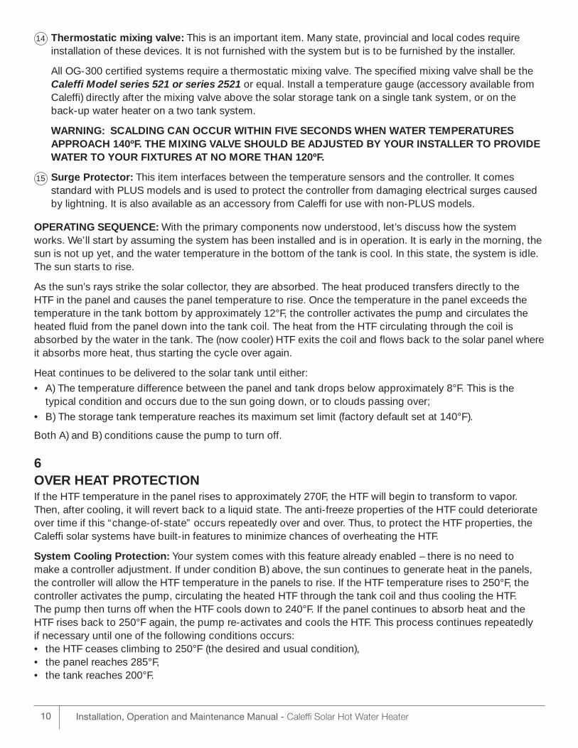
Heat Diverting: Though the three methods above provide a high level of protection against stagnation, theydepend on installation conditions, water use and geography and thus do not provide guaranteed protection.For maximum protection (except black-out), your installer may specify a Caleffi model (PLUS model). Thesemodels offer the ultimate in protection by means of a 4th method: diverting excess heat.
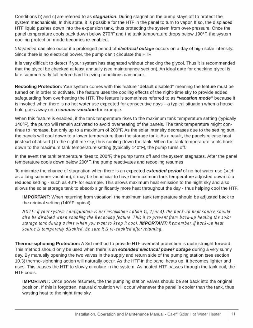
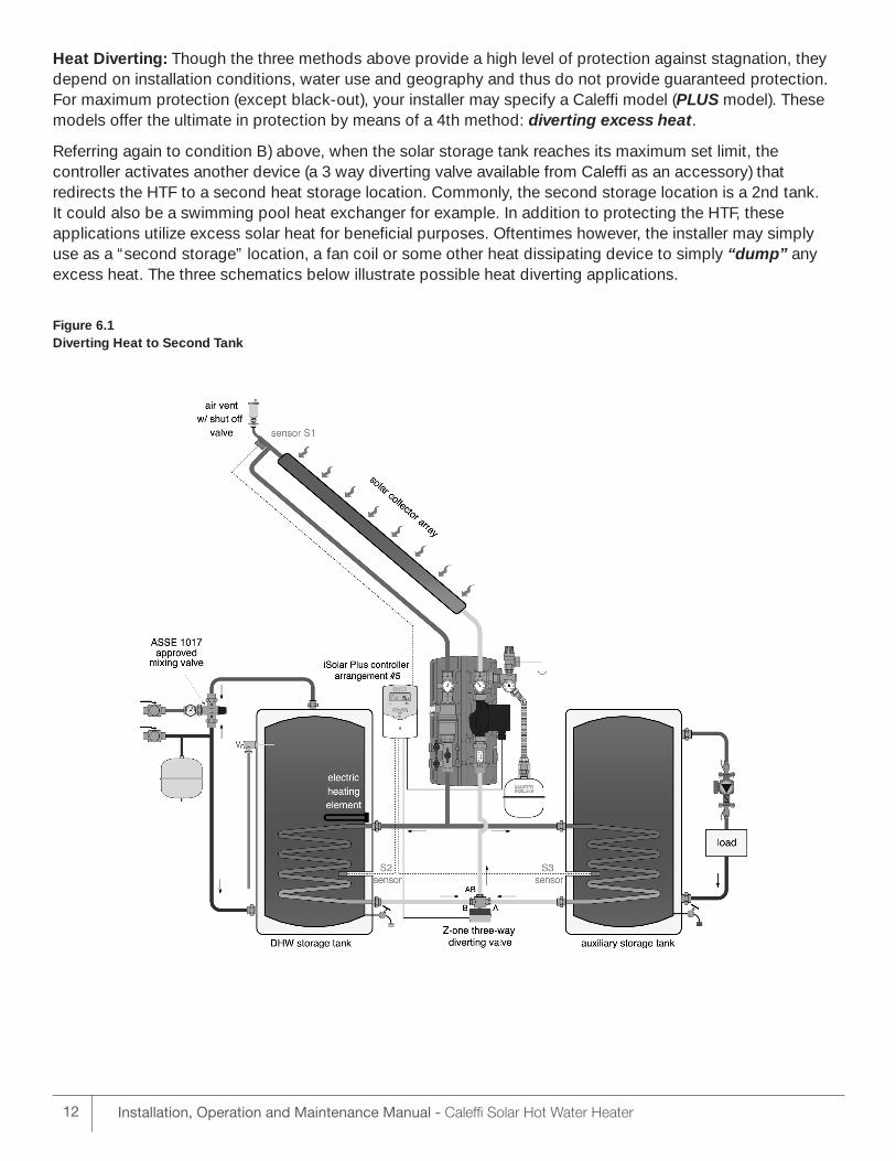
Referring again to condition B) above, when the solar storage tank reaches its maximum set limit, the controller activates another device (a 3 way diverting valve available from Caleffi as an accessory) that redirects the HTF to a second heat storage location. Commonly, the second storage location is a 2nd tank. It could also be a swimming pool heat exchanger for example. In addition to protecting the HTF, these applications utilize excess solar heat for beneficial purposes. Oftentimes however, the installer may simply use as a “second storage” location, a fan coil or some other heat dissipating device to simply “dump” anyexcess heat. The three schematics below illustrate possible heat diverting applications.
Figure 6.1Diverting Heat to Second Tank
12 Installation, Operation and Maintenance Manual - Caleffi Solar Hot Water Heater
13Installation, Operation and Maintenance Manual - Caleffi Solar Hot Water Heater
Figure 6.2Diverting Heat to Swimming Pool
Figure 6.3Diverting Heat to Dissipator
7INSTALLATION – SAFETY FIRST7.1 The installation shall conform to all federal, state and local regulations, codes, ordinances and standards
governing solar water heating system installations, and the contractor shall adhere to sound buildingsafety and trade practices. Special consideration must be given to building code requirements for thepenetration of structural members and fire rated assemblies.
7.2 The installer should consult www.osha.gov 2001Code of Federal Regulations, Chapter 29 Part 1926Safety and Health Regulations for Construction.
7.3 The installer shall have proper safety equipment when working on elevated surfaces, as per OSHA requirements. Fall protection equipment must be used with the proper training. Having a helper or two on site will ease installation.
7.4 The homeowner and installer shall confirm the location of all roof mounted components in advance of theinstallation.
7.5 The solar panels must be located in a structurally sound area of the roof that will be un-shaded for themajority of the day all year round. Adjacent buildings and trees should be checked for possible wintershading.
7.6 Before the installation the installer shall inspect the condition of the roof and notify the homeowner of anyexisting roof damage or necessary repairs.
8INSTALLATION – SPECIFIC REQUIREMENTSIn section nine, step-by-step procedures for installing a typical Caleffi system in a home are given. Several helpful photos and illustrations are included. The remainder of this section lists important general requirements for your solar system installation.
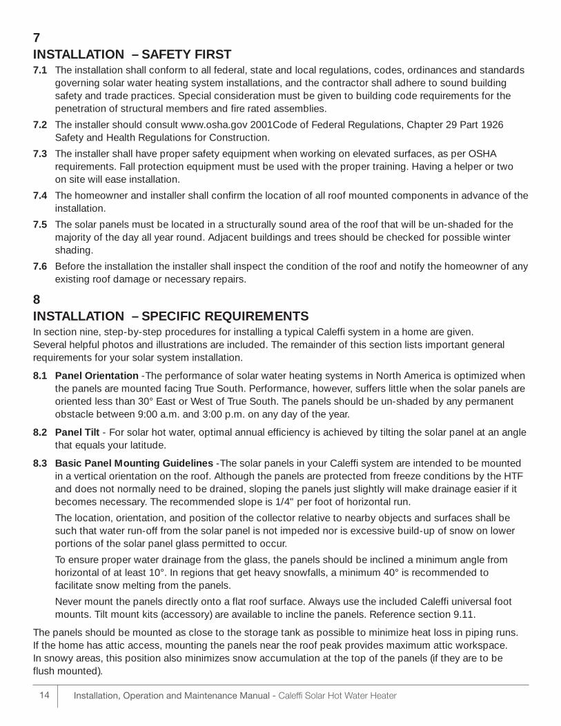
8.1 Panel Orientation -The performance of solar water heating systems in North America is optimized whenthe panels are mounted facing True South. Performance, however, suffers little when the solar panels areoriented less than 30° East or West of True South. The panels should be un-shaded by any permanentobstacle between 9:00 a.m. and 3:00 p.m. on any day of the year.
8.2 Panel Tilt - For solar hot water, optimal annual efficiency is achieved by tilting the solar panel at an anglethat equals your latitude.
8.3 Basic Panel Mounting Guidelines -The solar panels in your Caleffi system are intended to be mountedin a vertical orientation on the roof. Although the panels are protected from freeze conditions by the HTFand does not normally need to be drained, sloping the panels just slightly will make drainage easier if itbecomes necessary. The recommended slope is 1/4" per foot of horizontal run.
The location, orientation, and position of the collector relative to nearby objects and surfaces shall besuch that water run-off from the solar panel is not impeded nor is excessive build-up of snow on lowerportions of the solar panel glass permitted to occur.
To ensure proper water drainage from the glass, the panels should be inclined a minimum angle fromhorizontal of at least 10°. In regions that get heavy snowfalls, a minimum 40° is recommended to facilitate snow melting from the panels.
Never mount the panels directly onto a flat roof surface. Always use the included Caleffi universal footmounts. Tilt mount kits (accessory) are available to incline the panels. Reference section 9.11.
The panels should be mounted as close to the storage tank as possible to minimize heat loss in piping runs. If the home has attic access, mounting the panels near the roof peak provides maximum attic workspace. In snowy areas, this position also minimizes snow accumulation at the top of the panels (if they are to be flush mounted).
14 Installation, Operation and Maintenance Manual - Caleffi Solar Hot Water Heater
15Installation, Operation and Maintenance Manual - Caleffi Solar Hot Water Heater
Roofing Considerations: The solar panels should be mounted on the roof in accordance with these principles:
• The most important structural consideration is to securely anchor the solar panels and universal foot mounting hardware to the structural members of the roof with stainless steel fasteners. Please reference sections 9.5, 9.6, 9.7.
• Using the universal foot mounts will raise the panels from the roof surface to allow rainwater and debris to pass under the panels and allow proper ventilation of the roofing material. If the roof design or shape prevents the use of the Caleffi foot mounts, the panels must be raised from the roof by at least 1 1/2" of clearance.
• In selecting mounting hardware and fasteners it is important to avoid galvanic corrosion resulting from the direct contact of incompatible metals. Use of Caleffi aluminum mounting hardware and stainless steel fasteners, lock washers and round washers is recommended wherever possible. In climates subject to severe winters or high humidity use of galvanized fasteners is prohibited.
• Preserving the integrity of the roof membrane is important. Ensure that all roof penetrations required to plumb and mount the solar panels are properly flashed and sealed in accordance with standard roofing practices. Reference section 9.7 for recommended sealants.
• If the region is subject to hurricane conditions, additional steps may be required to secure the panels and mounting hardware to the structural members. In certain areas of the country, local building codes may require panel wind load testing or prescribe specific mounting procedures. Consult your local building department.
8.4 Panel Loop Pipe Insulation - Solar Flex is used for the solar panel cold supply and hot return lines.Solar Flex comes pre-insulated and includes union connections. Exposed connections should be insulated using the supplied UV resistant insulation and tape. Reference section 9.20.
8.5 Panel Plumbing - All vertical runs of SolarFlex between the storage tank and the panels should be supported at each story or at maximum intervals of ten feet (10'). Caleffi provides 4 specialized mountingbrackets for support. The brackets hold the SolarFlex securely without compressing the insulation. Reference section 9.14.
8.6 Back-Up System Connections - Interconnection of the back-up heating portion of the system to thesolar portion of the system shall be made in a manner which will not result in excessive temperature orpressure in the back-up heating system or bypassing of safety devices of the back-up system.
8.7 Low Voltage Wiring - The low voltage wiring used to connect the sensor wires is included with the SolarFlex – the wire is imbedded in the middle of the SolarFlex. Joining the sensor wire to the SolarFlexwire should be done using waterproof butt splices, or soldered connection with heat shrink protection, or waterproof telecom splice kits. Reference section 9.14.
8.8 Installing Solar Storage Tank, Expansion Tank and Pumping Station - When plumbing the solar storage tank and expansion tank, make sure all the components are accessible and easy to reach. Provide for clear access to the storage tank, pumping station, expansion tank, mixing valve (available asan accessory), controller and other key components. The controller should be located in close proximityto a 115 volt electrical receptacle.
Installation, Operation and Maintenance Manual - Caleffi Solar Hot Water Heater16
The storage tank should not be placed directly on an un-insulated floor or concrete slab. The tank should beplaced on a well insulated pad with a minimum R-value of 10. A 2" rigid polystyrene insulation pad is a goodsolution.
For a two tank system, position the solar storage tank in close proximity to the back-up hot water heater orboiler to simplify plumbing.
If a component in the potable water side of the system may require future service or maintenance, make theconnections with brass unions. Use only brass nipples and unions and copper and brass fittings in plumbingthe solar storage tank. The use of galvanized fittings or nipples, di-electric unions, CPVC, PVC or other plasticpipe is not recommended.
Hard copper connections to the city cold water supply line and the home hot water feed lines are recommended. The gaskets in standard water heater flex hose connectors can become brittle and compressed over time and begin leaking on the water heater. If not detected in a timely manner even a small drip or leak may cause serious damage to the tank’s electrical components or, in extreme cases, may cause the tank to leak from the outside in.
All interconnecting hot water piping and the final 5 feet of metallic cold water supply pipe leading to the system, or the length of piping which is accessible if less than 5 feet, shall be insulated with R-2.6 or greaterinsulation.
8.9 Building Related Installation Requirements
Firestopping - The SWH system components shall be assembled such that fire stopping shall be possible attime of installation, if required by local codes and ordinances.
Space Use - Solar components should not reduce or increase humidity, temperature or thermal radiation beyond acceptable levels or interfere with required headroom or air circulation space.
Building Penetrations - Penetrations of the building through which piping or wiring is passed shall not reduce or impair the function of the enclosure. Penetrations through walls or other surfaces shall not allow intrusion by insects and/or vermin. Required roof penetrations shall be made in accordance with applicablecodes and also by practices recommended by the National Roofing Contractors Association.
Water Damage - Collectors and support shall be installed in such a manner that water flowing off the collector surface will not damage the building or cause premature erosion of the roof.
Structural Supports - Neither wind loading (including uplift) nor the additional weight of filled solar panelsshall exceed the live or dead load ratings of the building, roof, roof anchorage, foundation or soil. Solar panelsupports shall not impose undue stresses on the solar panels. The design load shall be as specified by thecodes in force at the installation site and shall include an additional load due to snow accumulation for applicable locations.
Penetration Of Structural Members - When penetrations are required in structural members to accompanypassage of solar components, those modified structural members shall comply with local building codes.
Protection From Thermal Deterioration - Building materials adjacent to solar equipment shall not be exposed to elevated temperatures which could accelerate their deterioration. Many non-metal roofing materials will soften in the temperature range of 140-180ºF and begin to degrade above this temperature.
Penetrations Through Fire-Rated Assemblies - Penetrations through fire-rated assemblies etc. shall not reduce the building's fire resistance required by local codes, ordinances and applicable standards.
Emergency Egress and Access -The design and installation of systems shall not impair emergency movement of the building occupants.
Installation Manual - Caleffi Solar Hot Water Heating Kit 17
Illustrative Installation Steps
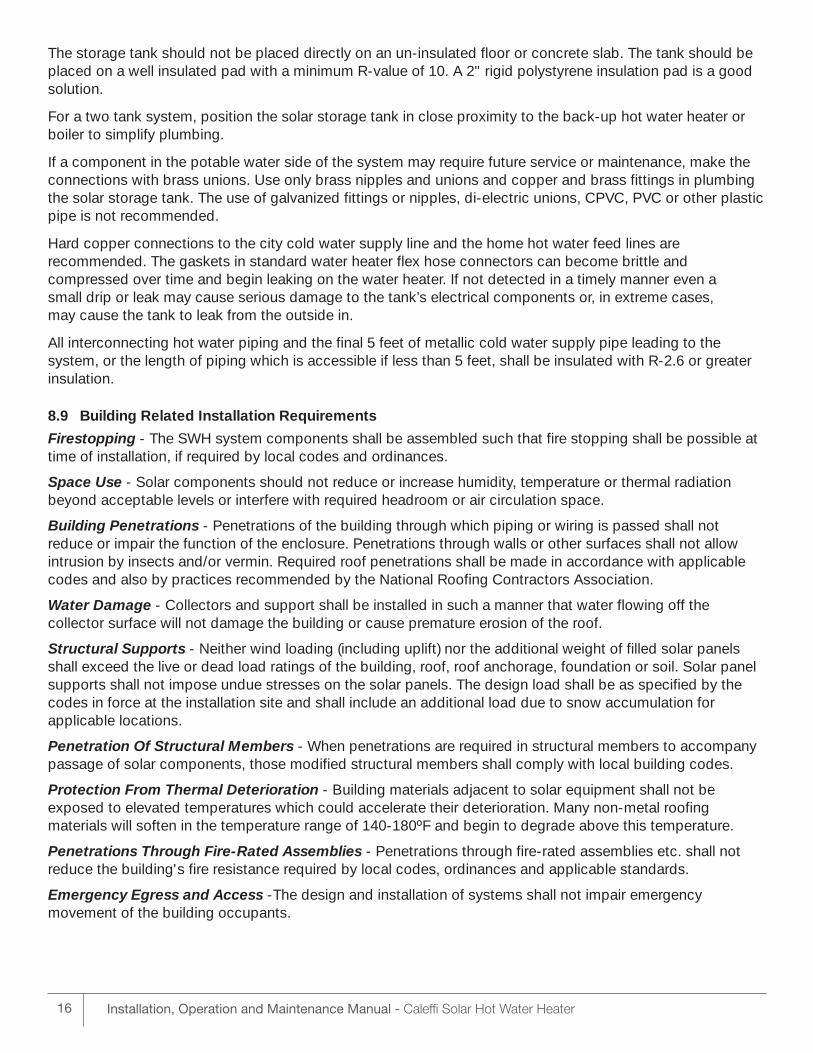
9.1
Overview
This section is a step by stepphoto instruction of a typical residential solar hot water heaterinstallation. A 45 minute DVD video is also available showingthese installation steps and is included with the Caleffi solar system.
We show only the solar side of thesystem being installed. Since theback-up equipment and installationprocedures are site and applicationspecific, these are not included.
Though not representative of everyinstallation, these instructions willgreatly simplify the task of installingany Caleffi solar system.
9.2
Tools and Supplies Required
• Ladder(s) for roof installs
• Fall protection gear
• Ropes, slings or webbing to liftpanels from ground to roof
• Tape measure
• String or chalk line
• Drill and screw gun
• Miscellaneous wrenches and channel lock pliers formounting hardware and connecting unions
• Small flat head and Phillipsscrew drivers
• Wire splices and wire crimpers
• System filling pump andfill/purge hoses
• Large bucket (5 or 10 gallon)
• Roofing sealant
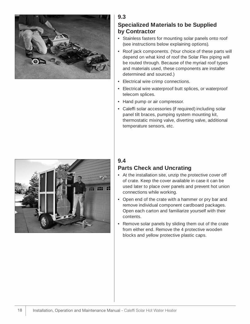
9.3Specialized Materials to be Supplied by Contractor • Stainless fasters for mounting solar panels onto roof
(see instructions below explaining options).
• Roof jack components. (Your choice of these parts willdepend on what kind of roof the Solar Flex piping willbe routed through. Because of the myriad roof typesand materials used, these components are installer determined and sourced.)
• Electrical wire crimp connections.
• Electrical wire waterproof butt splices, or waterprooftelecom splices.
• Hand pump or air compressor.
• Caleffi solar accessories (if required) including solarpanel tilt braces, pumping system mounting kit, thermostatic mixing valve, diverting valve, additionaltemperature sensors, etc.
9.4Parts Check and Uncrating • At the installation site, unzip the protective cover off
of crate. Keep the cover available in case it can be used later to place over panels and prevent hot unionconnections while working.
• Open end of the crate with a hammer or pry bar and remove individual component cardboard packages.Open each carton and familiarize yourself with theircontents.
• Remove solar panels by sliding them out of the cratefrom either end. Remove the 4 protective woodenblocks and yellow protective plastic caps.
Installation, Operation and Maintenance Manual - Caleffi Solar Hot Water Heater18
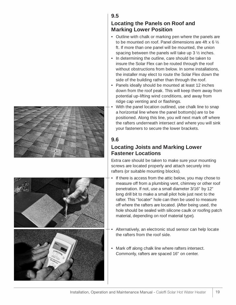
9.5Locating the Panels on Roof and Marking Lower Position • Outline with chalk or marking pen where the panels are
to be mounted on roof. Panel dimensions are 4ft x 6 ½ft. If more than one panel will be mounted, the unionspacing between the panels will take up 3 ½ inches.
• In determining the outline, care should be taken to insure the Solar Flex can be routed through the roofwithout obstructions from below. In some installations,the installer may elect to route the Solar Flex down theside of the building rather than through the roof.
• Panels ideally should be mounted at least 12 inchesdown from the roof peak. This will keep them away frompotential up-lifting wind conditions, and away fromridge cap venting and or flashings.
• With the panel location outlined, use chalk line to snapa horizontal line where the panel bottom(s) are to be positioned. Along this line, you will next mark off wherethe rafters underneath intersect and where you will sinkyour fasteners to secure the lower brackets.
9.6Locating Joists and Marking Lower Fastener LocationsExtra care should be taken to make sure your mountingscrews are located properly and attach securely intorafters (or suitable mounting blocks).
• If there is access from the attic below, you may chose tomeasure off from a plumbing vent, chimney or other roofpenetration. If not, use a small diameter 3/16” by 12”long drill bit to make a small pilot hole just next to therafter. This “locater” hole can then be used to measureoff where the rafters are located. (After being used, thehole should be sealed with silicone caulk or roofing patchmaterial, depending on roof material type).
• Alternatively, an electronic stud sensor can help locatethe rafters from the roof side.
• Mark off along chalk line where rafters intersect. Commonly, rafters are spaced 16” on center.
Installation, Operation and Maintenance Manual - Caleffi Solar Hot Water Heater 19
20 Installation, Operation and Maintenance Manual - Caleffi Solar Hot Water Heater
• For each panel, choose the best intersections to place 2 mounting brackets and ensure good panel support.Bracket locations should be no more than approximately12” away from the panel side.
9.7Mounting Lower Brackets • With the locations for each lower bracket determined,
place roof sealant on the underside of the brackets.“EternaBond” double stick roofing tape is an excellentproduct for sealing the mounting hardware to a wide variety of roofing materials. “Through the Roof” is another good roofing caulk available in squeeze orcaulk gun tubes. Check with a roofing supply companyfor these or comparable products.
• Secure the brackets into the roof. Each bracket has two holes – for convenience, either hole may be used.Stainless steel lag or anchor bolts or corrosion resistantanchor screws for mounting to rafters are suggested.
• Always drill a pilot hole into the rafter before screwinginto them with a bolt. A drill 1/3 the diameter of the lagscrew diameter is recommended. Example: a 1/8” pilothole for a 3/8” lag bolt. Consult with a fastener supplierfor additional hardware advice.
• Be sure the brackets are mounted securely to providestrength against sliding and up-lift forces.
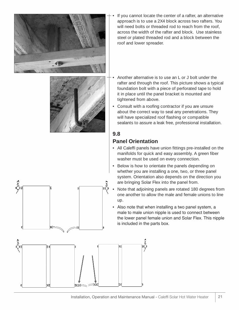
• If you cannot locate the center of a rafter, an alternativeapproach is to use a 2X4 block across two rafters. Youwill need bolts or threaded rod to reach from the roof,across the width of the rafter and block. Use stainlesssteel or plated threaded rod and a block between theroof and lower spreader.
• Another alternative is to use an L or J bolt under therafter and through the roof. This picture shows a typicalfoundation bolt with a piece of perforated tape to hold it in place until the panel bracket is mounted and tightened from above.
• Consult with a roofing contractor if you are unsureabout the correct way to seal any penetrations. Theywill have specialized roof flashing or compatiblesealants to assure a leak free, professional installation.
9.8Panel Orientation • All Caleffi panels have union fittings pre-installed on the
manifolds for quick and easy assembly. A green fiberwasher must be used on every connection.
• Below is how to orientate the panels depending onwhether you are installing a one, two, or three panelsystem. Orientation also depends on the direction youare bringing Solar Flex into the panel from.
• Note that adjoining panels are rotated 180 degrees fromone another to allow the male and female unions to lineup.
• Also note that when installing a two panel system, amale to male union nipple is used to connect betweenthe lower panel female union and Solar Flex. This nippleis included in the parts box.
21Installation, Operation and Maintenance Manual - Caleffi Solar Hot Water Heater
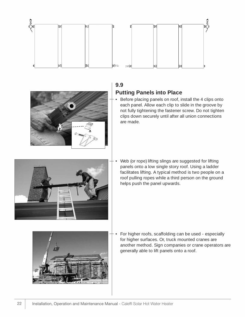
9.9Putting Panels into Place • Before placing panels on roof, install the 4 clips onto
each panel. Allow each clip to slide in the groove by not fully tightening the fastener screw. Do not tightenclips down securely until after all union connections are made.
• Web (or rope) lifting slings are suggested for lifting panels onto a low single story roof. Using a ladder facilitates lifting. A typical method is two people on aroof pulling ropes while a third person on the groundhelps push the panel upwards.
• For higher roofs, scaffolding can be used - especiallyfor higher surfaces. Or, truck mounted cranes are another method. Sign companies or crane operators aregenerally able to lift panels onto a roof.
Installation, Operation and Maintenance Manual - Caleffi Solar Hot Water Heater22
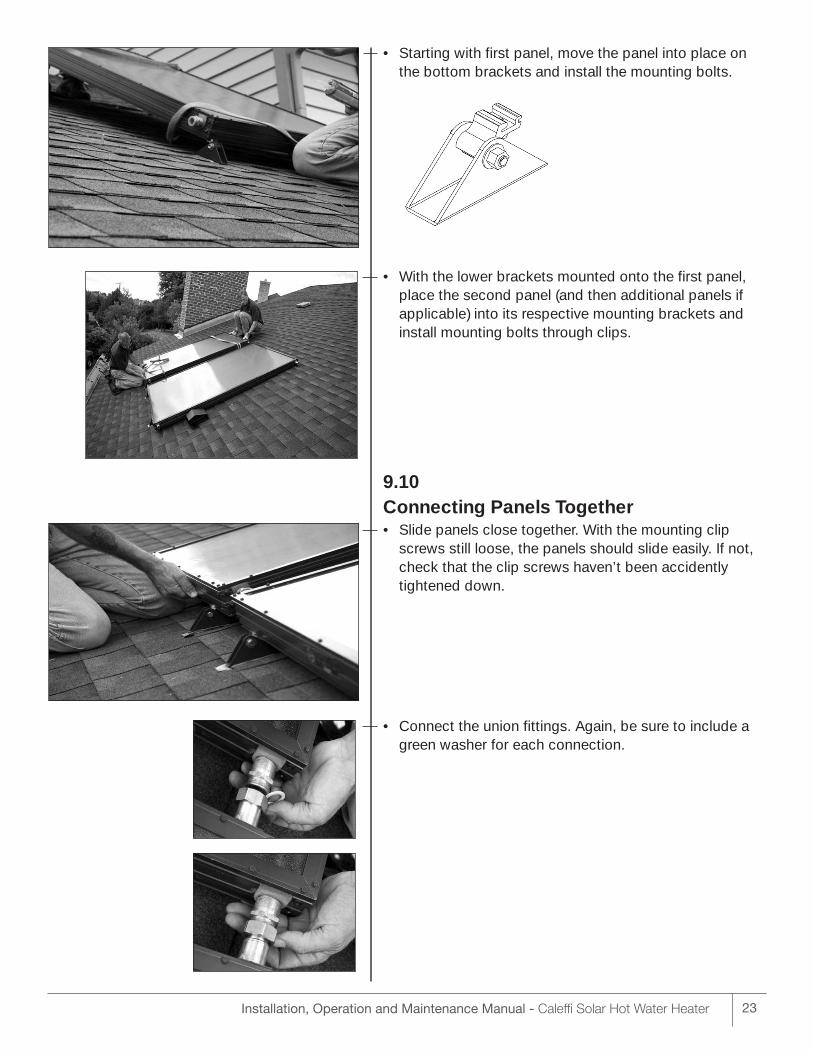
• Starting with first panel, move the panel into place onthe bottom brackets and install the mounting bolts.
• With the lower brackets mounted onto the first panel,place the second panel (and then additional panels ifapplicable) into its respective mounting brackets and install mounting bolts through clips.
9.10Connecting Panels Together • Slide panels close together. With the mounting clip
screws still loose, the panels should slide easily. If not,check that the clip screws haven’t been accidentlytightened down.
• Connect the union fittings. Again, be sure to include agreen washer for each connection.
Installation, Operation and Maintenance Manual - Caleffi Solar Hot Water Heater 23
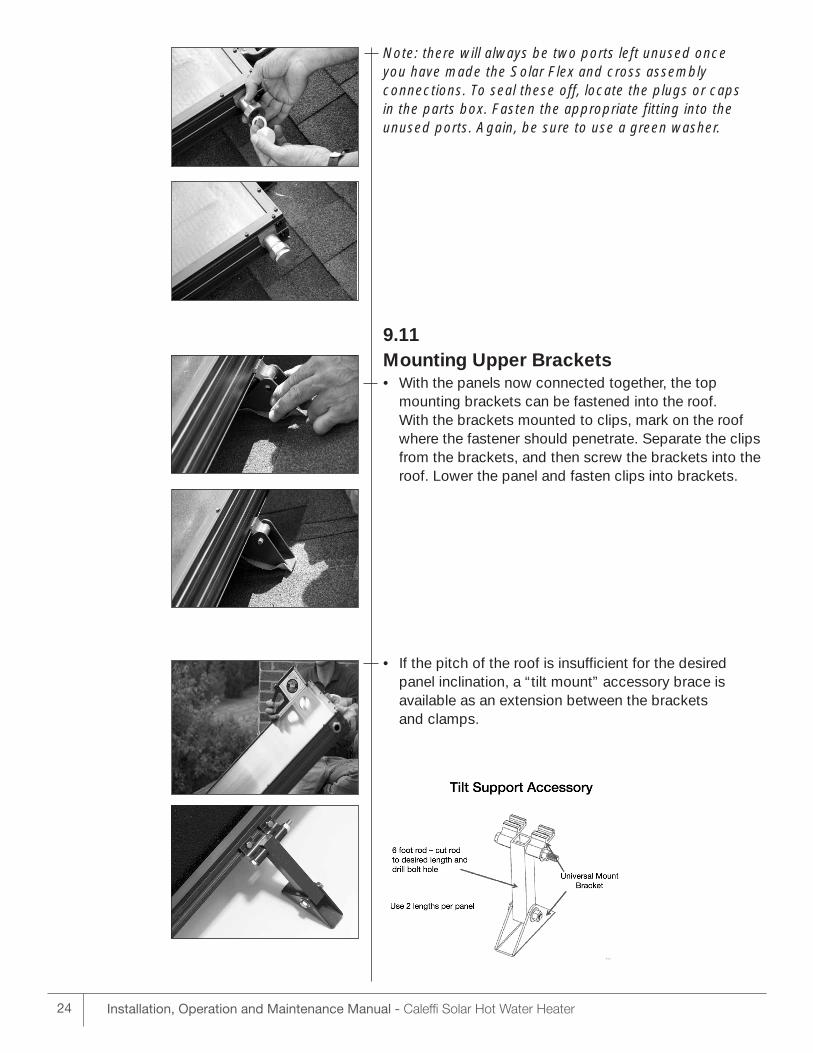
Note: there will always be two ports left unused once you have made the Solar Flex and cross assembly connections. To seal these off, locate the plugs or caps in the parts box. Fasten the appropriate fitting into the unused ports. Again, be sure to use a green washer.
9.11Mounting Upper Brackets • With the panels now connected together, the top
mounting brackets can be fastened into the roof. With the brackets mounted to clips, mark on the roofwhere the fastener should penetrate. Separate the clipsfrom the brackets, and then screw the brackets into theroof. Lower the panel and fasten clips into brackets.
• If the pitch of the roof is insufficient for the desiredpanel inclination, a “tilt mount” accessory brace is available as an extension between the brackets and clamps.
Installation, Operation and Maintenance Manual - Caleffi Solar Hot Water Heater24
Installation, Operation and Maintenance Manual - Caleffi Solar Hot Water Heater 25
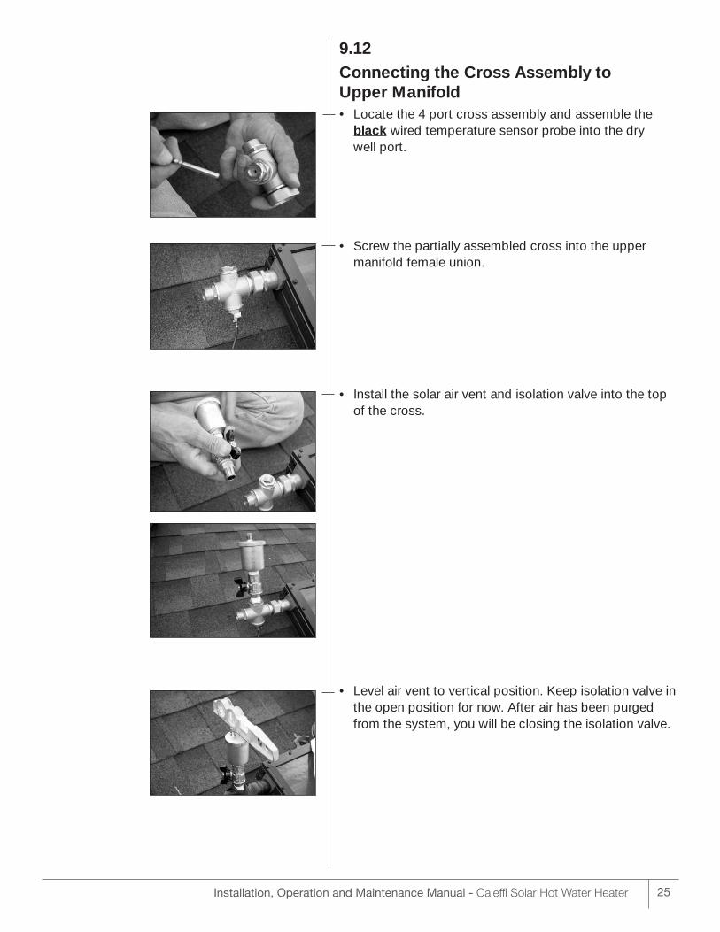
9.12Connecting the Cross Assembly to Upper Manifold • Locate the 4 port cross assembly and assemble the
black wired temperature sensor probe into the dry well port.
• Screw the partially assembled cross into the uppermanifold female union.
• Install the solar air vent and isolation valve into the topof the cross.
• Level air vent to vertical position. Keep isolation valve inthe open position for now. After air has been purgedfrom the system, you will be closing the isolation valve.
26 Installation, Operation and Maintenance Manual - Caleffi Solar Hot Water Heater
9.13Running Solar Flex through Roof and Connecting to Solar Panel • For flashing the Solar Flex through the roof we suggest
using a PVC or ABS sleeve to route the Solar Flex. Wechose for this installation to make two roof penetrations –one to be made near the panel outlet and one to bemade near the panel inlet. (Alternatively, we could havechosen to make only one larger hole penetration and runthe Solar Flex up through the roof, and then split it toconnect to the supply and return ports on the panel).
Note: a 4” sleeve will accommodate Solar Flex that hasn’tbeen split into supply and return. Split sections of SolarFlex will fit inside a 3” sleeve.
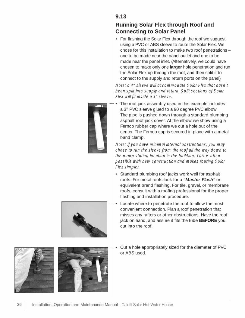
• The roof jack assembly used in this example includes a 3” PVC sleeve glued to a 90 degree PVC elbow. The pipe is pushed down through a standard plumbingasphalt roof jack cover. At the elbow we show using aFernco rubber cap where we cut a hole out of the center. The Fernco cap is secured in place with a metalband clamp.
Note: If you have minimal internal obstructions, you maychose to run the sleeve from the roof all the way down tothe pump station location in the building. This is often possible with new construction and makes routing SolarFlex simpler.
• Standard plumbing roof jacks work well for asphaltroofs. For metal roofs look for a “Master-Flash” orequivalent brand flashing. For tile, gravel, or membraneroofs, consult with a roofing professional for the properflashing and installation procedure.
• Locate where to penetrate the roof to allow the mostconvenient connection. Plan a roof penetration thatmisses any rafters or other obstructions. Have the roofjack on hand, and assure it fits the tube BEFORE youcut into the roof.
• Cut a hole appropriately sized for the diameter of PVCor ABS used.
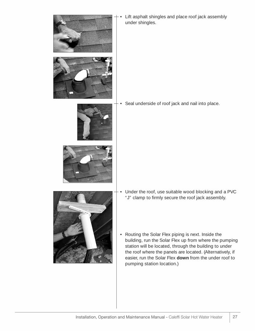
• Lift asphalt shingles and place roof jack assembly under shingles.
• Seal underside of roof jack and nail into place.
• Under the roof, use suitable wood blocking and a PVC“J” clamp to firmly secure the roof jack assembly.
• Routing the Solar Flex piping is next. Inside the building, run the Solar Flex up from where the pumpingstation will be located, through the building to under the roof where the panels are located. (Alternatively, ifeasier, run the Solar Flex down from the under roof topumping station location.)
27Installation, Operation and Maintenance Manual - Caleffi Solar Hot Water Heater
28 Installation, Operation and Maintenance Manual - Caleffi Solar Hot Water Heater
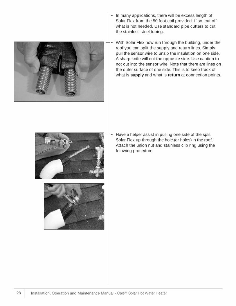
• In many applications, there will be excess length ofSolar Flex from the 50 foot coil provided. If so, cut offwhat is not needed. Use standard pipe cutters to cutthe stainless steel tubing.
• With Solar Flex now run through the building, under theroof you can split the supply and return lines. Simplypull the sensor wire to unzip the insulation on one side.A sharp knife will cut the opposite side. Use caution tonot cut into the sensor wire. Note that there are lines onthe outer surface of one side. This is to keep track ofwhat is supply and what is return at connection points.
• Have a helper assist in pulling one side of the split Solar Flex up through the hole (or holes) in the roof. Attach the union nut and stainless clip ring using thefolowing procedure.
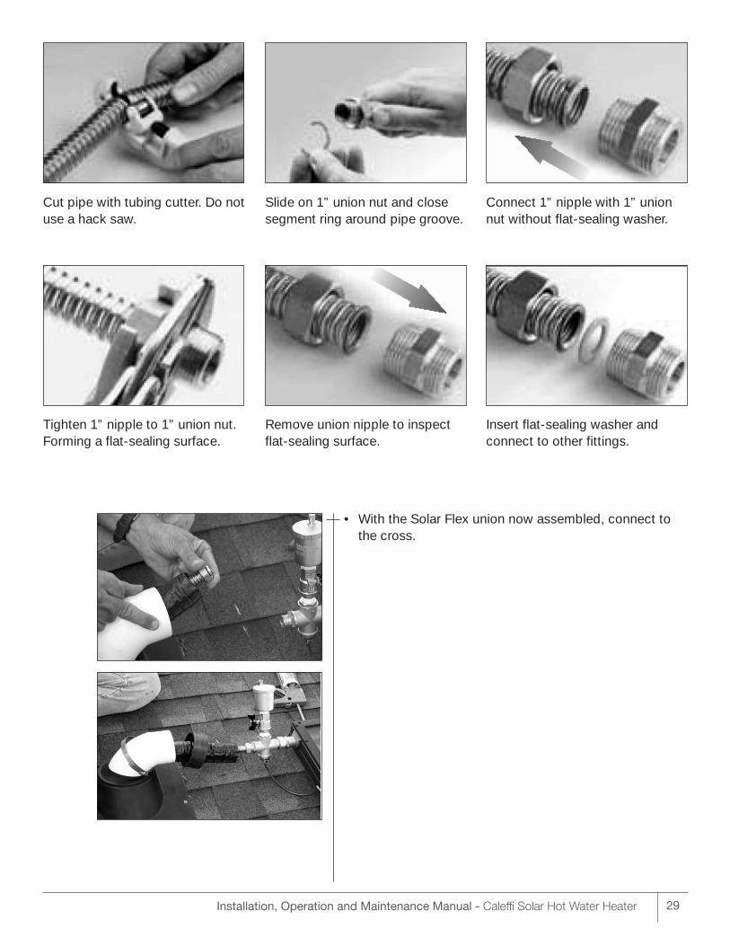
Cut pipe with tubing cutter. Do notuse a hack saw.
Slide on 1” union nut and closesegment ring around pipe groove.
Connect 1” nipple with 1” unionnut without flat-sealing washer.
Tighten 1” nipple to 1” union nut.Forming a flat-sealing surface.
Remove union nipple to inspectflat-sealing surface.
Insert flat-sealing washer andconnect to other fittings.
• With the Solar Flex union now assembled, connect tothe cross.
29Installation, Operation and Maintenance Manual - Caleffi Solar Hot Water Heater
30 Installation, Operation and Maintenance Manual - Caleffi Solar Hot Water Heater
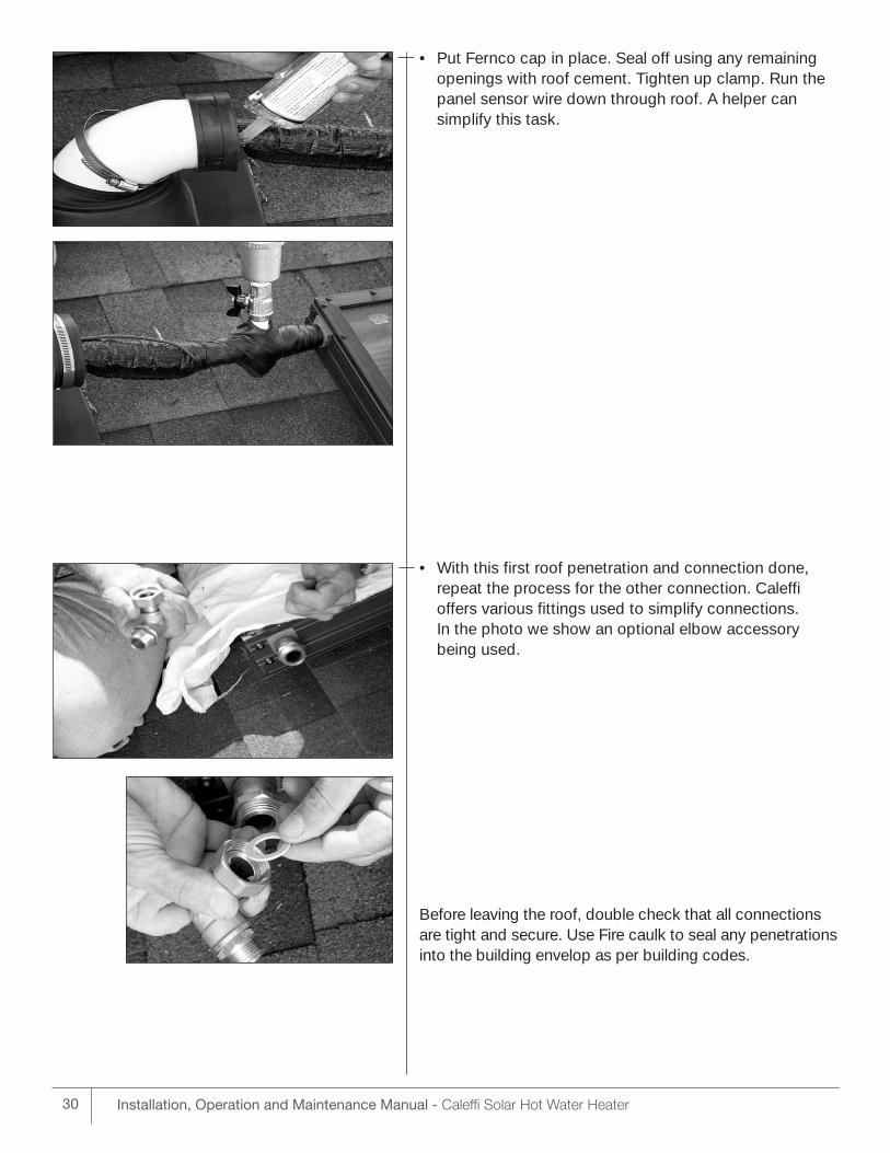
• Put Fernco cap in place. Seal off using any remainingopenings with roof cement. Tighten up clamp. Run thepanel sensor wire down through roof. A helper can simplify this task.
• With this first roof penetration and connection done, repeat the process for the other connection. Caleffi offers various fittings used to simplify connections. In the photo we show an optional elbow accessorybeing used.
Before leaving the roof, double check that all connectionsare tight and secure. Use Fire caulk to seal any penetrationsinto the building envelop as per building codes.
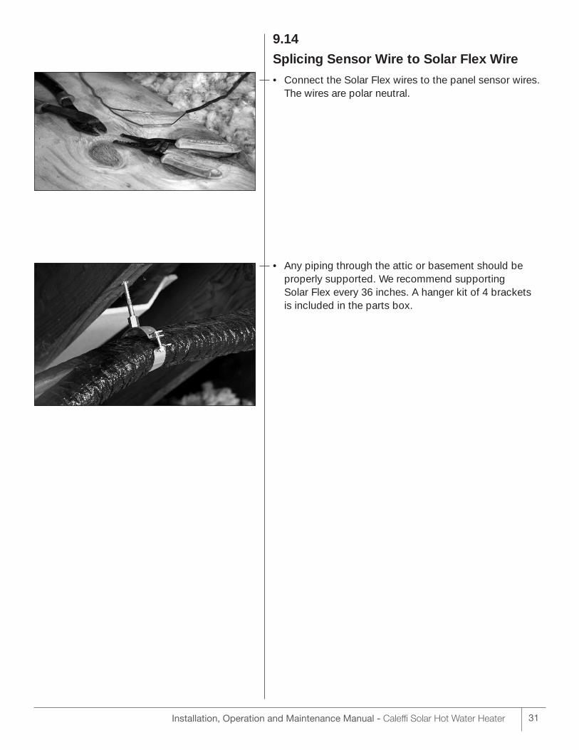
9.14
Splicing Sensor Wire to Solar Flex Wire
• Connect the Solar Flex wires to the panel sensor wires.The wires are polar neutral.
• Any piping through the attic or basement should beproperly supported. We recommend supporting Solar Flex every 36 inches. A hanger kit of 4 brackets is included in the parts box.
31Installation, Operation and Maintenance Manual - Caleffi Solar Hot Water Heater
32 Installation, Operation and Maintenance Manual - Caleffi Solar Hot Water Heater
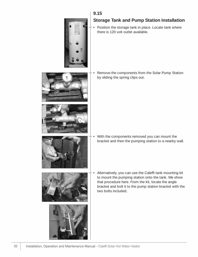
9.15
Storage Tank and Pump Station Installation
• Position the storage tank in place. Locate tank wherethere is 120 volt outlet available.
• Remove the components from the Solar Pump Stationby sliding the spring clips out.
• With the components removed you can mount thebracket and then the pumping station to a nearby wall.
• Alternatively, you can use the Caleffi tank mounting kitto mount the pumping station onto the tank. We showthat procedure here. From the kit, locate the anglebracket and bolt it to the pump station bracket with thetwo bolts included.
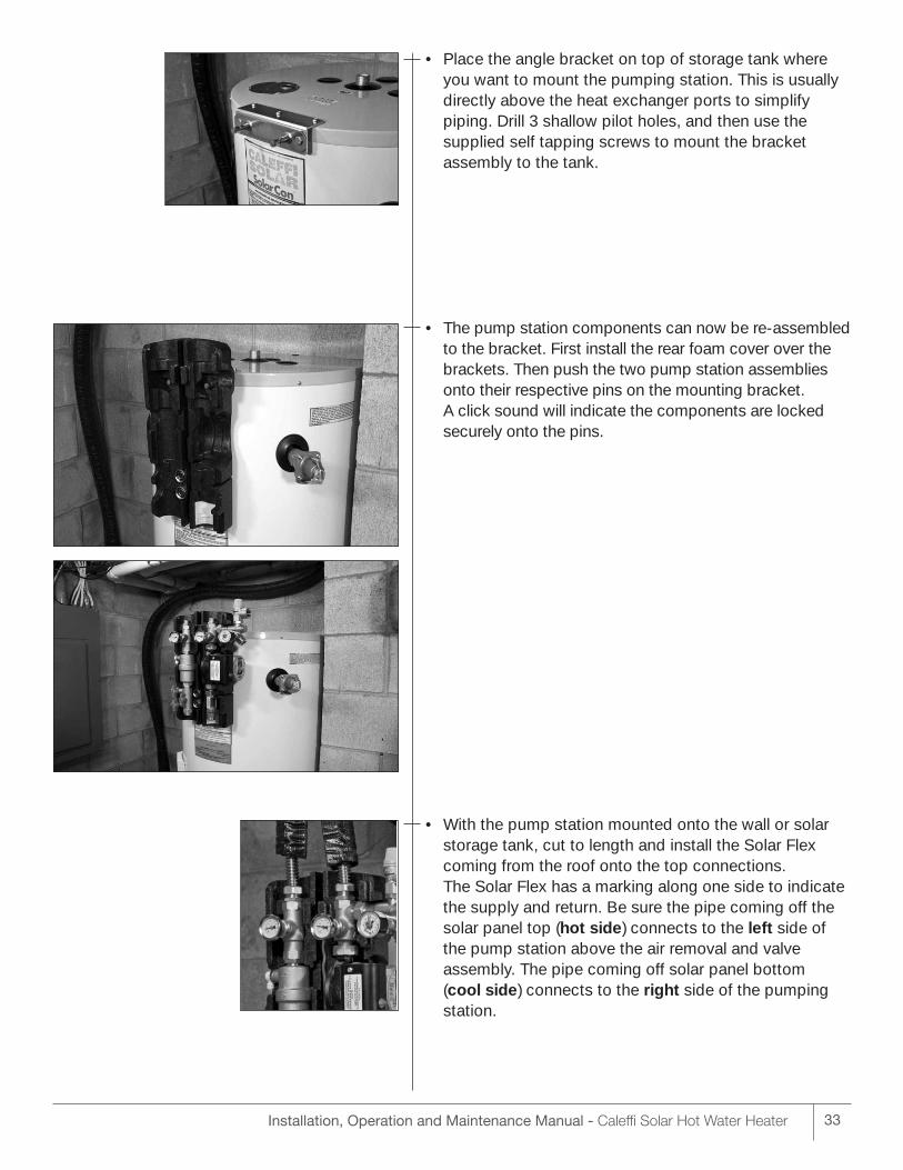
• Place the angle bracket on top of storage tank whereyou want to mount the pumping station. This is usuallydirectly above the heat exchanger ports to simplify piping. Drill 3 shallow pilot holes, and then use the supplied self tapping screws to mount the bracket assembly to the tank.
• The pump station components can now be re-assembledto the bracket. First install the rear foam cover over thebrackets. Then push the two pump station assembliesonto their respective pins on the mounting bracket. A click sound will indicate the components are lockedsecurely onto the pins.
• With the pump station mounted onto the wall or solarstorage tank, cut to length and install the Solar Flexcoming from the roof onto the top connections. The Solar Flex has a marking along one side to indicatethe supply and return. Be sure the pipe coming off thesolar panel top (hot side) connects to the left side of the pump station above the air removal and valve assembly. The pipe coming off solar panel bottom (cool side) connects to the right side of the pumpingstation.
33Installation, Operation and Maintenance Manual - Caleffi Solar Hot Water Heater
34 Installation, Operation and Maintenance Manual - Caleffi Solar Hot Water Heater
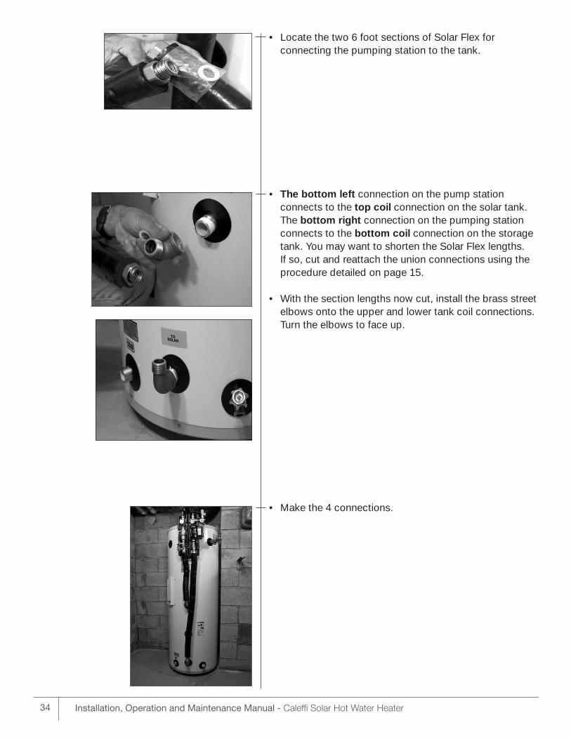
• Locate the two 6 foot sections of Solar Flex for connecting the pumping station to the tank.
• The bottom left connection on the pump station connects to the top coil connection on the solar tank.The bottom right connection on the pumping stationconnects to the bottom coil connection on the storagetank. You may want to shorten the Solar Flex lengths. If so, cut and reattach the union connections using theprocedure detailed on page 15.
• With the section lengths now cut, install the brass streetelbows onto the upper and lower tank coil connections.Turn the elbows to face up.
• Make the 4 connections.
9.16
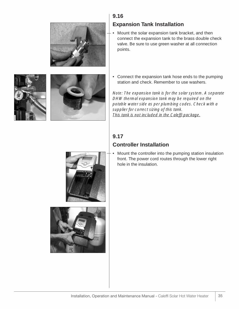
Expansion Tank Installation
• Mount the solar expansion tank bracket, and then connect the expansion tank to the brass double checkvalve. Be sure to use green washer at all connectionpoints.
• Connect the expansion tank hose ends to the pumpingstation and check. Remember to use washers.
Note: The expansion tank is for the solar system. A separateDHW thermal expansion tank may be required on thepotable water side as per plumbing codes. Check with asupplier for correct sizing of this tank. This tank is not included in the Caleffi package.
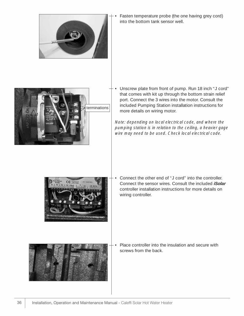
9.17
Controller Installation
• Mount the controller into the pumping station insulationfront. The power cord routes through the lower righthole in the insulation.
35Installation, Operation and Maintenance Manual - Caleffi Solar Hot Water Heater
terminations
36 Installation, Operation and Maintenance Manual - Caleffi Solar Hot Water Heater
• Fasten temperature probe (the one having grey cord)into the bottom tank sensor well.
• Unscrew plate from front of pump. Run 18 inch “J cord”that comes with kit up through the bottom strain reliefport. Connect the 3 wires into the motor. Consult the included Pumping Station installation instructions formore details on wiring motor.
Note: depending on local electrical code, and where thepumping station is in relation to the ceiling, a heavier gagewire may need to be used. Check local electrical code.
• Connect the other end of “J cord” into the controller.Connect the sensor wires. Consult the included iSolarcontroller installation instructions for more details onwiring controller.
• Place controller into the insulation and secure withscrews from the back.
9.18 Filling & Flushing
Filling Solar Storage TankFirst, open up a hot water faucet within the house. Then open the cold water isolation ball valve to thesolar tank. After the tank is filled, close the hot waterfaucet and inspect all threaded fittings and solder jointsfor leaks.
Warning: For a single tank system, never activate thecircuit breaker controlling the electrical heating element until the solar storage tank is completely filled withwater. This will prevent “dry firing” of the heating element. The electrical heating element can be destroyed almost instantaneously if not completely submerged in water when activated. Make sure thewater heater circuit breaker is off until the solar storagetank is completely filled.
Flush and Pressure Test Solar LoopThough the Caleffi solar system components comecapped at the ports and minimize chances of dirt getting in, you may want to flush the system to insuredirt is not present.
A convenient method is to simply use a garden hosewith at least 30 psi pressure. First, make sure the airvent ball valve is closed on the solar panel. Open up thetwo check valves on pumping station. Ref section 10.3Attach garden hose to the bottom bib on the pump station. Connect another hose to the top bib and putthe end into a drain. Close the middle isolation valve.Turn on the water and let it run for 5-10 minutes. By this
time, the water draining out of the hose should be voidof air bubbles.
Close off the top bib valve. Check for leaks at all connections. Tighten down if necessary. Turn off waterand let the water in the loop drain back out of the topand bottom bibs. Loosen the solar flex connection tobottom of storage tank to drain the remainder of thewater. Tighten solar flex connection back up. Insulatethe two brass elbow connections to the storagetank.Reset the two check valves on pumping station.
Note: if the outside temperature is below freezing, use apressurized air test method to avoid any water freezingproblems.
Filling & Pressurizing Solar Loop
• You are now ready to fill the solar loop. First, determine the pressure to set the solar loop to. You will want to obtain 20 psi gage pressure at theloops’ highest point. This pressure will keep the system working optimally, and prevent glycolfrom flashing into vapor in the panels.
Procedure:
- Starting with 20 psi, for every floor level between solar panel and storage tank top,add another 5 psi
- Example: Tank is in basement and panels are on roof of one story home. Set pressure to = 20 psi + 5 psi/floor * 2 floors = 30 psi
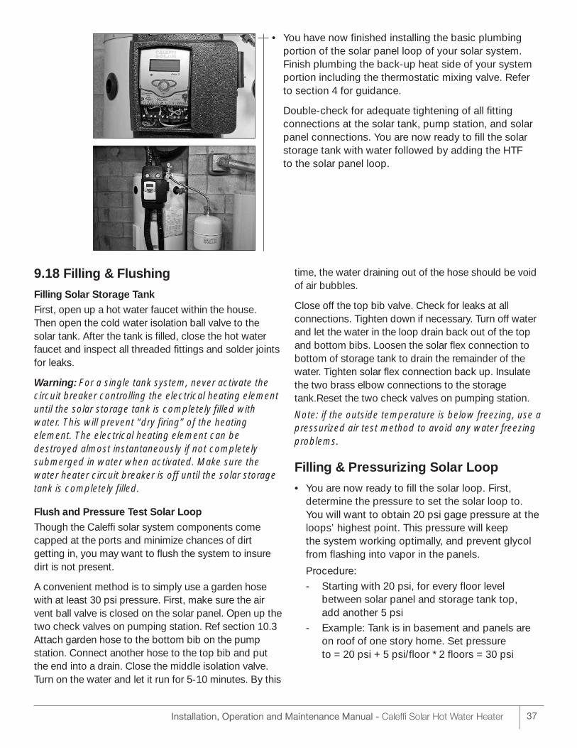
• You have now finished installing the basic plumbingportion of the solar panel loop of your solar system. Finish plumbing the back-up heat side of your systemportion including the thermostatic mixing valve. Refer to section 4 for guidance.
Double-check for adequate tightening of all fitting connections at the solar tank, pump station, and solarpanel connections. You are now ready to fill the solarstorage tank with water followed by adding the HTF to the solar panel loop.
37Installation, Operation and Maintenance Manual - Caleffi Solar Hot Water Heater
38 Installation, Operation and Maintenance Manual - Caleffi Solar Hot Water Heater
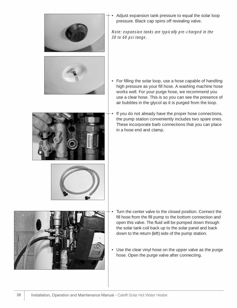
• Adjust expansion tank pressure to equal the solar looppressure. Black cap spins off revealing valve.
Note: expansion tanks are typically pre-charged in the 30 to 60 psi range.
• For filling the solar loop, use a hose capable of handlinghigh pressure as your fill hose. A washing machine hoseworks well. For your purge hose, we recommend youuse a clear hose. This is so you can see the presence ofair bubbles in the glycol as it is purged from the loop.
• If you do not already have the proper hose connections,the pump station conveniently includes two spare ones.These incorporate barb connections that you can placein a hose end and clamp.
• Turn the center valve to the closed position. Connect thefill hose from the fill pump to the bottom connection andopen this valve. The fluid will be pumped down throughthe solar tank coil back up to the solar panel and backdown to the return (left) side of the pump station.
• Use the clear vinyl hose on the upper valve as the purgehose. Open the purge valve after connecting.
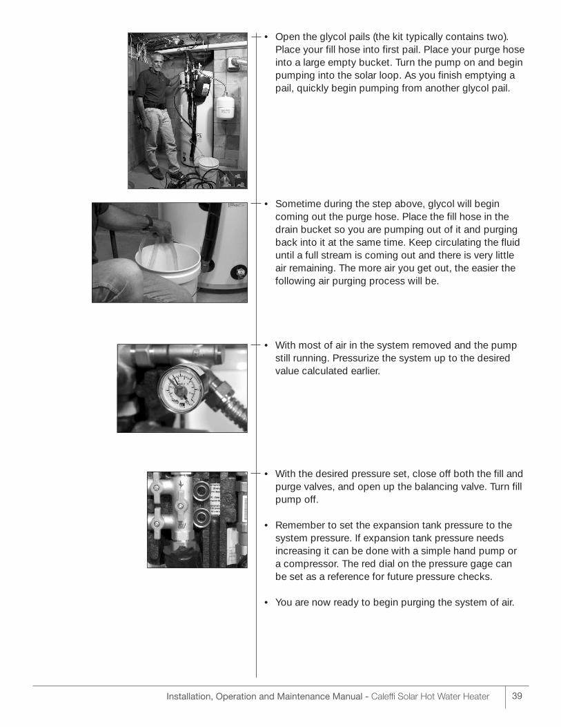
• Open the glycol pails (the kit typically contains two).Place your fill hose into first pail. Place your purge hoseinto a large empty bucket. Turn the pump on and beginpumping into the solar loop. As you finish emptying apail, quickly begin pumping from another glycol pail.
• Sometime during the step above, glycol will begin coming out the purge hose. Place the fill hose in thedrain bucket so you are pumping out of it and purgingback into it at the same time. Keep circulating the fluiduntil a full stream is coming out and there is very little air remaining. The more air you get out, the easier thefollowing air purging process will be.
• With most of air in the system removed and the pumpstill running. Pressurize the system up to the desiredvalue calculated earlier.
• With the desired pressure set, close off both the fill andpurge valves, and open up the balancing valve. Turn fillpump off.
• Remember to set the expansion tank pressure to thesystem pressure. If expansion tank pressure needs increasing it can be done with a simple hand pump or a compressor. The red dial on the pressure gage can be set as a reference for future pressure checks.
• You are now ready to begin purging the system of air.
39Installation, Operation and Maintenance Manual - Caleffi Solar Hot Water Heater
40 Installation, Operation and Maintenance Manual - Caleffi Solar Hot Water Heater
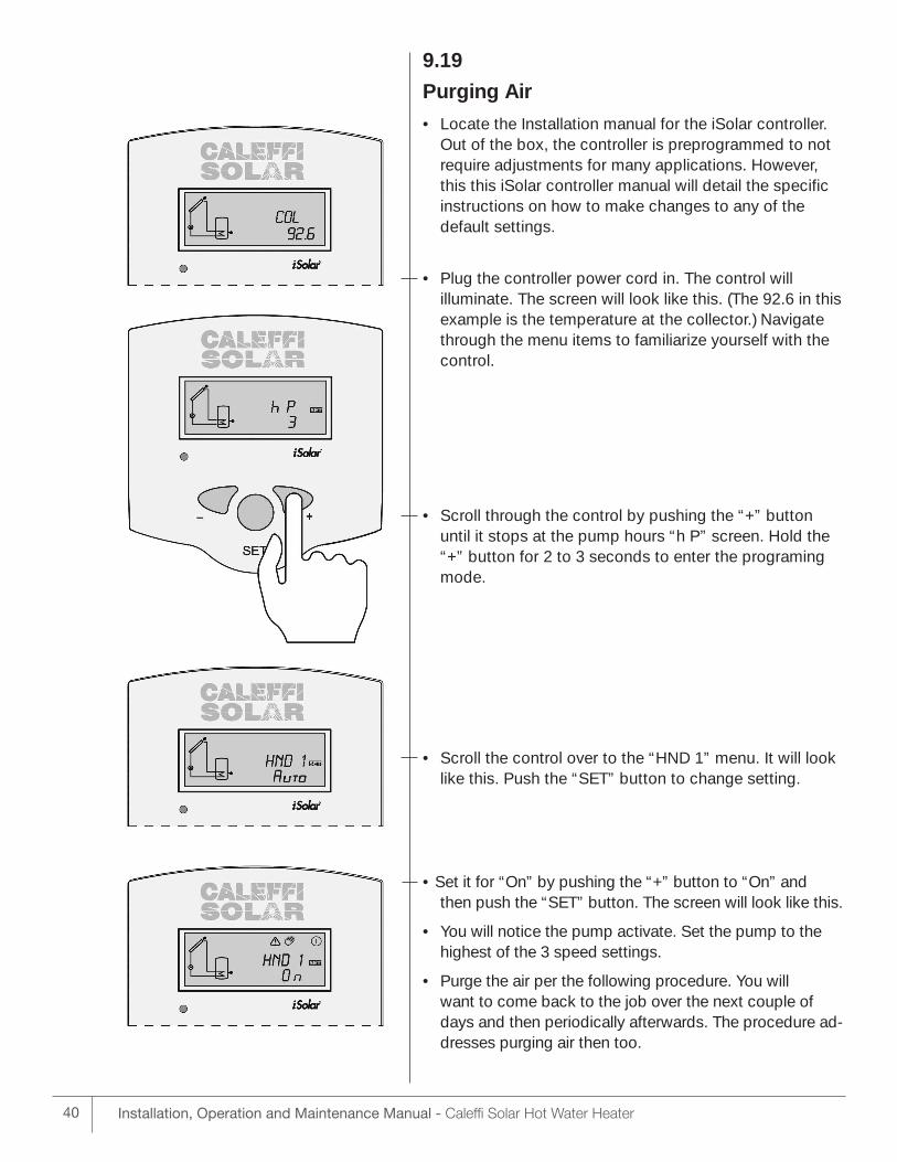
9.19
Purging Air
• Locate the Installation manual for the iSolar controller.Out of the box, the controller is preprogrammed to notrequire adjustments for many applications. However,this this iSolar controller manual will detail the specificinstructions on how to make changes to any of the default settings.
• Plug the controller power cord in. The control will illuminate. The screen will look like this. (The 92.6 in thisexample is the temperature at the collector.) Navigatethrough the menu items to familiarize yourself with thecontrol.
• Scroll through the control by pushing the “+” button until it stops at the pump hours “h P” screen. Hold the“+” button for 2 to 3 seconds to enter the programingmode.
• Scroll the control over to the “HND 1” menu. It will looklike this. Push the “SET” button to change setting.
• Set it for “On” by pushing the “+” button to “On” andthen push the “SET” button. The screen will look like this.
• You will notice the pump activate. Set the pump to thehighest of the 3 speed settings.
• Purge the air per the following procedure. You will want to come back to the job over the next couple ofdays and then periodically afterwards. The procedure ad-dresses purging air then too.
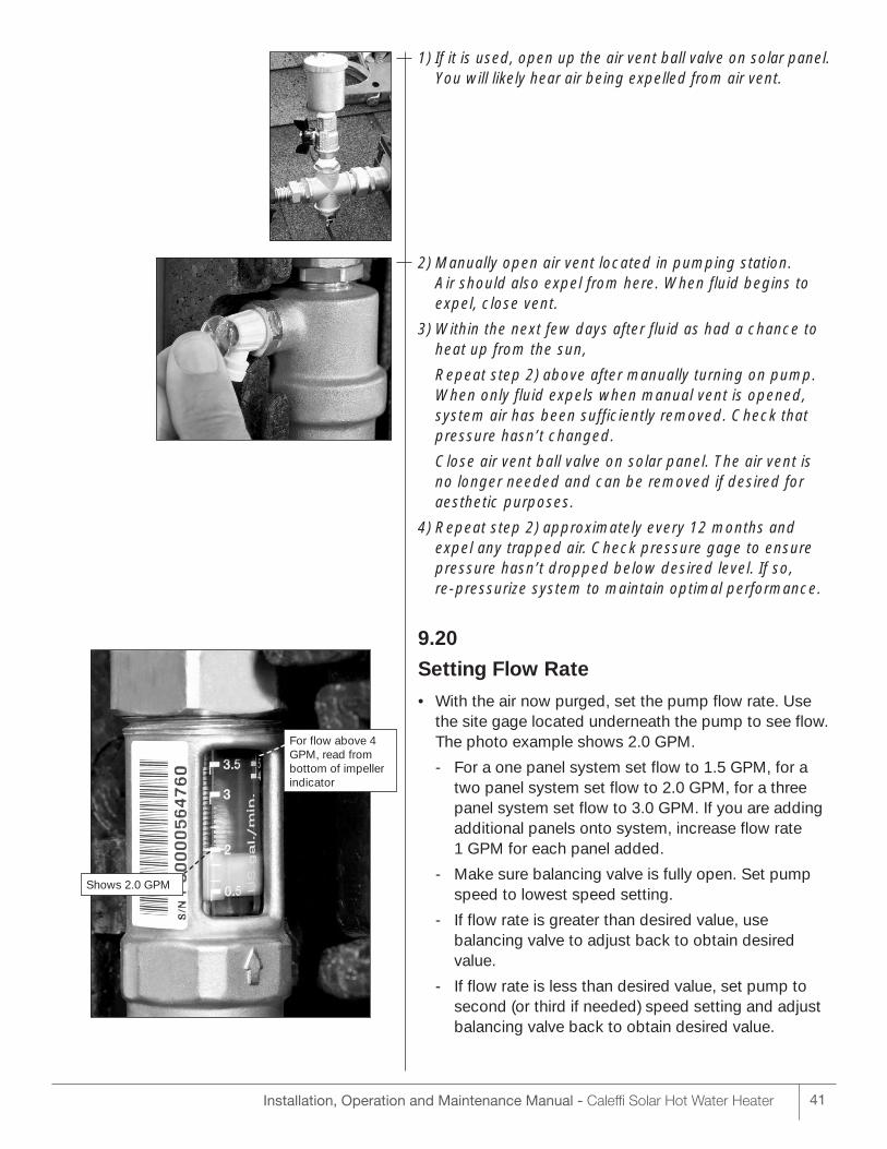
Shows 2.0 GPM
For flow above 4GPM, read frombottom of impellerindicator
1) If it is used, open up the air vent ball valve on solar panel.You will likely hear air being expelled from air vent.
2) Manually open air vent located in pumping station. Air should also expel from here. When fluid begins toexpel, close vent.
3) Within the next few days after fluid as had a chance toheat up from the sun,
Repeat step 2) above after manually turning on pump.When only fluid expels when manual vent is opened,system air has been sufficiently removed. Check thatpressure hasn’t changed.
Close air vent ball valve on solar panel. The air vent is no longer needed and can be removed if desired foraesthetic purposes.
4) Repeat step 2) approximately every 12 months andexpel any trapped air. Check pressure gage to ensurepressure hasn’t dropped below desired level. If so, re-pressurize system to maintain optimal performance.
9.20
Setting Flow Rate
• With the air now purged, set the pump flow rate. Usethe site gage located underneath the pump to see flow.The photo example shows 2.0 GPM.
- For a one panel system set flow to 1.5 GPM, for a two panel system set flow to 2.0 GPM, for a three panel system set flow to 3.0 GPM. If you are adding additional panels onto system, increase flow rate 1 GPM for each panel added.
- Make sure balancing valve is fully open. Set pump speed to lowest speed setting.
- If flow rate is greater than desired value, use balancing valve to adjust back to obtain desired value.
- If flow rate is less than desired value, set pump to second (or third if needed) speed setting and adjust balancing valve back to obtain desired value.
41Installation, Operation and Maintenance Manual - Caleffi Solar Hot Water Heater
42 Installation, Operation and Maintenance Manual - Caleffi Solar Hot Water Heater
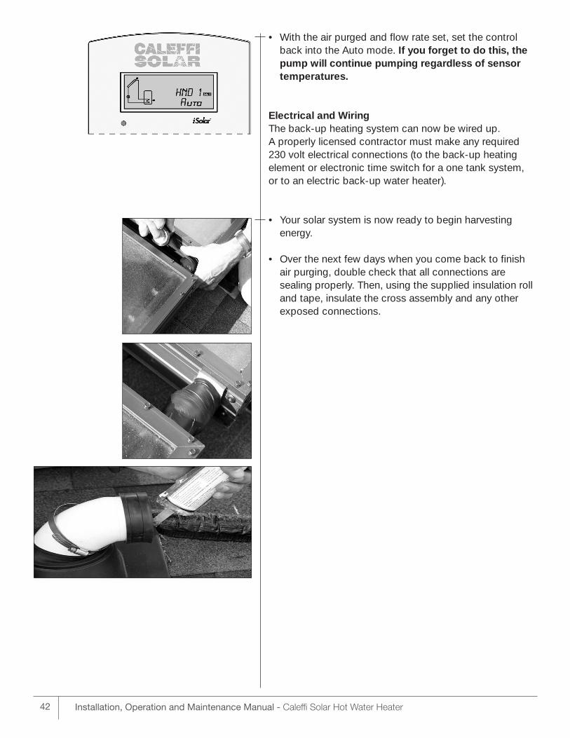
• With the air purged and flow rate set, set the controlback into the Auto mode. If you forget to do this, thepump will continue pumping regardless of sensor temperatures.
Electrical and Wiring The back-up heating system can now be wired up. A properly licensed contractor must make any required230 volt electrical connections (to the back-up heating element or electronic time switch for a one tank system, or to an electric back-up water heater).
• Your solar system is now ready to begin harvesting energy.
• Over the next few days when you come back to finishair purging, double check that all connections are sealing properly. Then, using the supplied insulation rolland tape, insulate the cross assembly and any other exposed connections.
43Installation, Operation and Maintenance Manual - Caleffi Solar Hot Water Heater
10OPERATING INSTRUCTIONS10.1 Changing Controller Default Settings - With the exception of manually turning the pump on and
off (ref section 9.19) , the default control settings allow plug and play capability for the majority of basic hot water heating applications. To change any default settings on the controller, reference the iSolar Controller installation manual. However, here are some of the more common changes an installer might invoke when using the iSolar 2 or the iSolar Plus controllers:
Storage Tank Max Temperature - The default setting is 140°F. Some installers might choose to adjust as low as 120°F, or as high as 160°F. In all cases where outgoing water from a water heater can exceed 120°F, using a 3 way thermostatic mixing valve guards against temperatures of potentially scalding levels.
Recooling Protection – Described earlier in section 6.
Minimum Pump Speed – The Caleffi controller automatically increases and decreases pump speedfrom 40% to 100% of maximum to correspond with how much heat is being harvested by the solarpanels. This feature minimizes electrical consumption by the pump, and optimizes the heat transfer efficiency in the storage tank. In installations with Solar Flex runs greater than the standard 50 feet coillength, 40% may be too low to keep the check valves fully open. The installer may elect to increase the minimum value to 50 or 60% to create sufficient pump head to keep the checks open and deliverspecified flow.
Heat Metering – The control can be programmed to measure the amount of heat that has been produced by the solar panels. Some solar system owners might desire knowing how much energy their investment is producing. The heat measurement units are KWh. To enable Heat Metering, a thirdsensor (accessory) must be used and wired to the controller and connected to the S4 sensor input. The sensor should be placed on the pipe leading out of the storage tank to the panel. The heat measurement is on a total accumulated basis and the control can be re-set to value 0.
10.2 iSolar Plus Controls Programming - Caleffi Solar systems featuring the iSolar Plus controller give additional application flexibility. Please consult the iSolar Plus Controller manual for detailed steps toprogram the controller.
Heat Diversion – Described earlier in section 6.
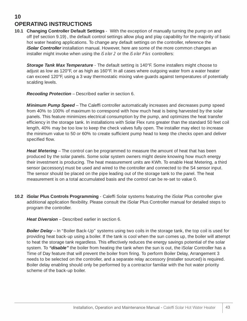
Boiler Delay – In “Boiler Back-Up” systems using two coils in the storage tank, the top coil is used forproviding heat back-up using a boiler. If the tank is cool when the sun comes up, the boiler will attemptto heat the storage tank regardless. This effectively reduces the energy savings potential of the solarsystem. To “disable” the boiler from heating the tank when the sun is out, the iSolar Controller has aTime of Day feature that will prevent the boiler from firing. To perform Boiler Delay, Arrangement 3needs to be selected on the controller, and a separate relay accessory (installer sourced) is required.Boiler delay enabling should only be performed by a contractor familiar with the hot water priorityscheme of the back-up boiler.
Installation, Operation and Maintenance Manual - Caleffi Solar Hot Water Heater44
Figure 10.1Example Schematic Showing Boiler Delay
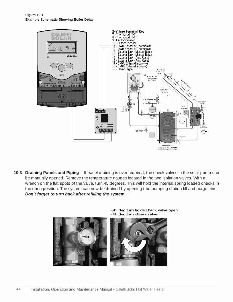
10.3 Draining Panels and Piping - If panel draining is ever required, the check valves in the solar pump canbe manually opened. Remove the temperature gauges located in the two isolation valves. With awrench on the flat spots of the valve, turn 45 degrees. This will hold the internal spring loaded checks inthe open position. The system can now be drained by opening tthe pumping station fill and purge bibs.Don’t forget to turn back after refilling the system.
Installation, Operation and Maintenance Manual - Caleffi Solar Hot Water Heater 45
10.4 ISOLATING THE MAJOR COMPONENTS AND SYSTEM SHUT DOWN PROCEDURES
Your solar water heating system is designed so key components can be easily isolated for emergencyrepairs or routine maintenance. By shutting a single valve you can isolate the entire system from thepressurized cold water supply line (reference item 3 in figures 4.1, 4.2, 4.3, 4.4).
The solar loop can be isolated from the solar storage tank by closing the two isolation valves on thepumping station. See figure 10.3 above. If the pressure in this loop drops or you find a glycol leak shutthese valves and contact your installation contractor. Turn the circulating pump off by either unpluggingthe controller, or setting the controller to the “off” position.
In two tank systems the solar storage tank can be isolated from the back-up water heater. Referencefigures 4.3 and 4.4. In the event isolation is required, the two normally open valves (item 1) that connectto the solar hot water heater should be closed and the normally closed valve (item 2) should be opened.
10.5 EXTENDED SUMMER VACATION
Solar water heating systems can build up very high temperatures when there is no daily draw on thesystem. If your system isn’t set up to perform heat diverting and a short summer vacation is planned,heat can be dissipated in the system by enabling Recooling (ref section 6).
During extended summer vacations (4 weeks or more) it is advisable to either cover the solar collectorswith an opaque material or to manually drain the HTF from the solar panels. Caleffi recommends thatyou cover the collectors if practical.
If draining the HTF in the solar loop is chosen, follow instructions in section 10.3 above. Only the fluidvolume in the panels need to be drained out - there is no need to drain the entire system. DO NOTDUMP HTF INTO A STORM SEWER, ON THE GROUND OR INTO ANY BODY OF WATER. BECAREFUL. THE HTF MAY BE EXTREMELY HOT!
When you return home contact your service contractor to recharge the system with HTF. After the system has been recharged, have the controller reset to the “automatic” position.
10.6 Solar Loop Pressure
On a sunny day when the system is operational, the pressure in your solar loop should not exceed 60 psig. Contact your solar contractor if the loop pressure exceeds this threshold.
11MAINTENANCE11.1 Heat Transfer Fluid Quality
The chemical composition of the HTF may change over time. The HTF quality should be monitored on aperiodic basis – at least annually. After summer and before any chance of the first freeze is an idealtime. A drop in ph can indicate the system has been stagnating frequently. The cause should be determined and corrected. Consult with a qualified contractor for the correct course of action.
To test the pH level, use a digital ph tester or tight range litmus paper. Remove a small sample of thefluid from the purge valve on the pump station (see 255/256 series Pumping Station manual for valve location.) A small sample of several tablespoons in a clear jar is sufficient. pH should be between 8.1and 12.0. Fluid with pH between 7.5 and 8.1 can be conditioned by your contractor using an inhibitorboost. Fluid with pH above 12.0 or that is dark, dirty or has an acidic smell should be replaced.
The HTF freeze protection level should be checked annually. A refract meter is the best tool for this.Freeze/ burst protection should be - 75°F.
Reference Appendix 1 which shows details on HTF maintenance.
Installation, Operation and Maintenance Manual - Caleffi Solar Hot Water Heater46
11.2 Piping and External InsulationOn an annual basis, all piping should be checked for leakage at joints, shut-off valves, and unions. Any damaged external insulation should be repaired or replaced.
11.2 Wiring and ConnectionsOn an annual basis, check wiring and connections, including sensor wiring and splices. Look for signsof overheating, discoloration, corrosion or loose connections. Any damaged wiring should be repairedor replaced.
11.3 Fluid LeaksIf you detect a glycol or water leak, or the glycol loop pressure drops unexpectedly, contact your installation contractor immediately to diagnose the problem and recharge the system.
11.4 Solar Storage Tank T&P Relief ValveOn an annual basis, the temperature and pressure relief valve should be checked for proper operation.First, attach a drain line to the valve to direct the water discharge to an open drain. This is very important because the temperature of the discharge could be very hot. Second, lift the lever at the endof the valve several times. The valve should operate freely and return to its original position properly. If water does not flow out of the valve, remove and inspect for corrosion or obstructions. Replace with a new valve if necessary. Do not repair the faulty valve as this may cause improper operation.
11.5 Solar Storage Tank Anode RodsAnode rods should be inspected twice in the first year and at least yearly once a time interval for in-spection has been developed. It is recommended to check the rod(s) six months after the heater is in-stalled. If the anode rod has reduced in size by two-thirds of its original diameter of 3/4” or shows signsof pitting, it is time for replacement. Take the following steps when changing the anode rod(s):
1. Shut off cold water supply.
2. Open any faucet to relieve tank pressure.
3. Remove caps on water heater top; push insulation aside.
4. Use a 1 1/16” six-sided socket wrench and a breaker bar. Snap hard to break the anode rod seal.
5. Remove rod(s) and replace with new rod(s).
6. Turn water supply back on and leave faucet open until air is out of line.
7. Turn faucet off and check that new rod(s) doesn’t leak.
8. Snap caps back into place.
11.6 Solar Storage Tank FlushingThe solar indirect water heater is glass lined. Elements in the water such as lime, iron and other miner-als may accumulate in the heater. It is recommended that the tank be drained and flushed thoroughlyonce a year to prevent buildup in the tank.
11.7 Solar Panel ClarityIf you live in a dusty climate, once a month wash off dirt that settles on the solar panel glass. Cleanglass allows the solar panel to maintain a high level of thermal performance.
11.8 Expansion Tank Annually check condition of the solar expansion tank. Check to see if it is waterlogged by quicklypressing schrader valve stem at bottom of the tank. You should get a quick burst of air. If fluid showsup, the tank may be waterlogged and need replacement. Contact a qualified solar installer if the tankneeds replacement.
Installation, Operation and Maintenance Manual - Caleffi Solar Hot Water Heater 47
12
TROUBLE SHOOTINGSolar Storage TankTrouble shooting is detailed on page 17 of the Installation, commissioning and servicing instructions forNAS200 Series SolarCon solar water heater tank.
System Performance Trouble shooting is detailed in the back of the iSolar controller manual.
13PARTS, SERVICE AND WARRANTYPlease see Appendix 3 for warranty coverage. To obtain warranty service, contact your installation contractor orcall Caleffi North America, Inc. at 414-238-2360 (8-5 CST) for the name of an authorized contractor near you.
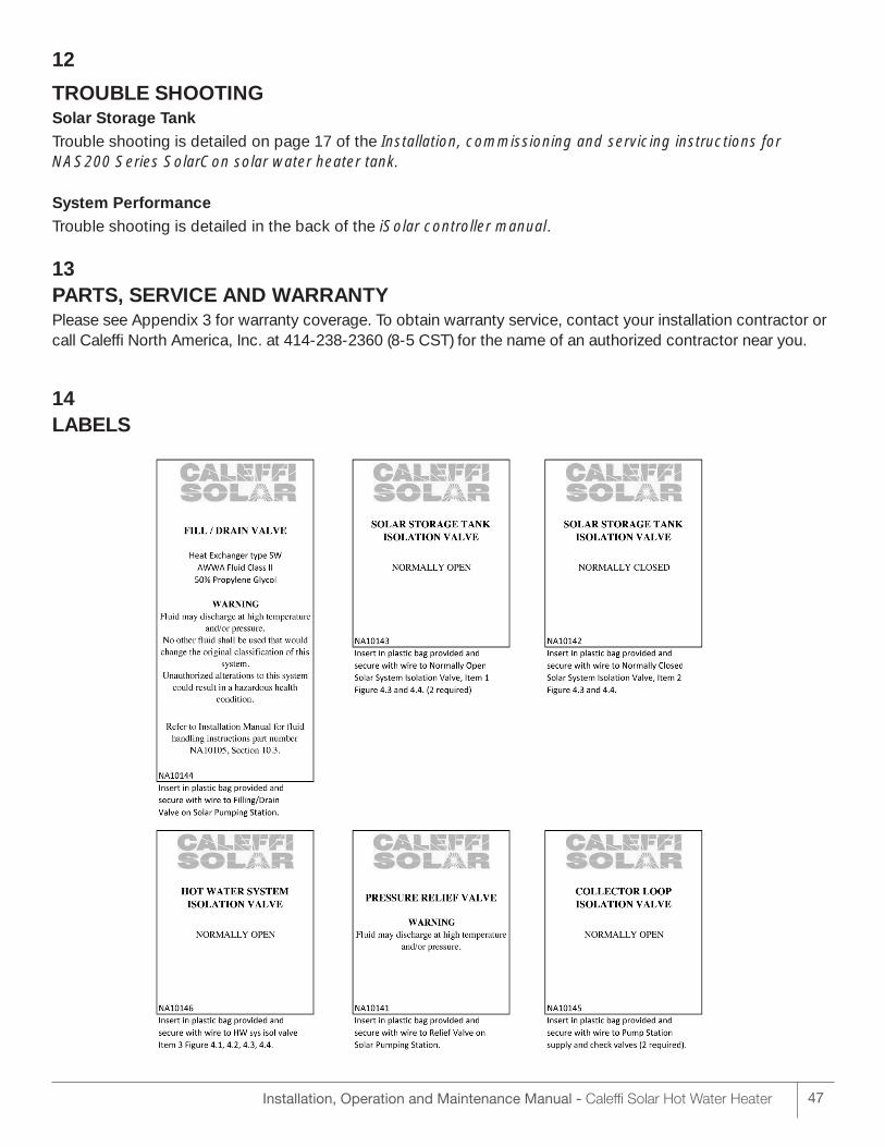
14LABELS
Installation, Operation and Maintenance Manual - Caleffi Solar Hot Water Heater48
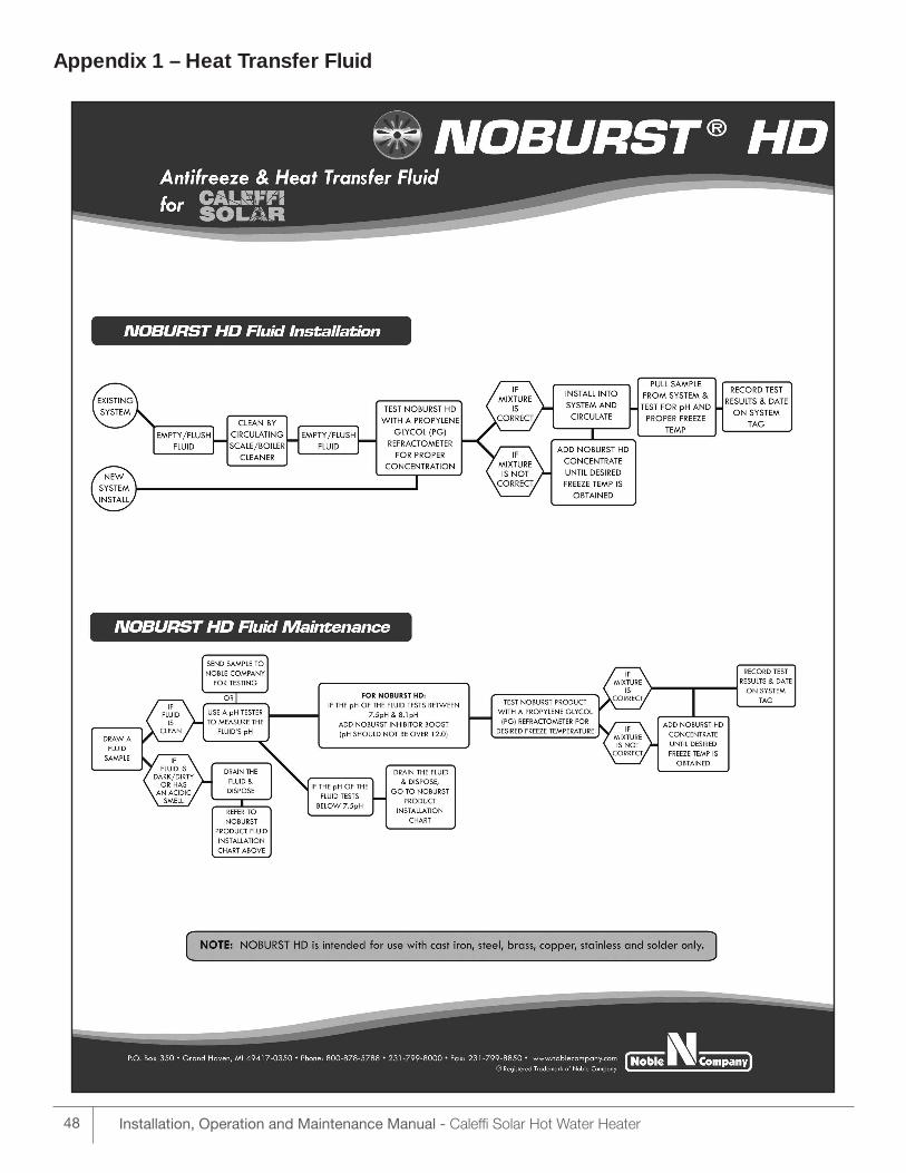
Appendix 1 – Heat Transfer Fluid
Installation, Operation and Maintenance Manual - Caleffi Solar Hot Water Heater 49
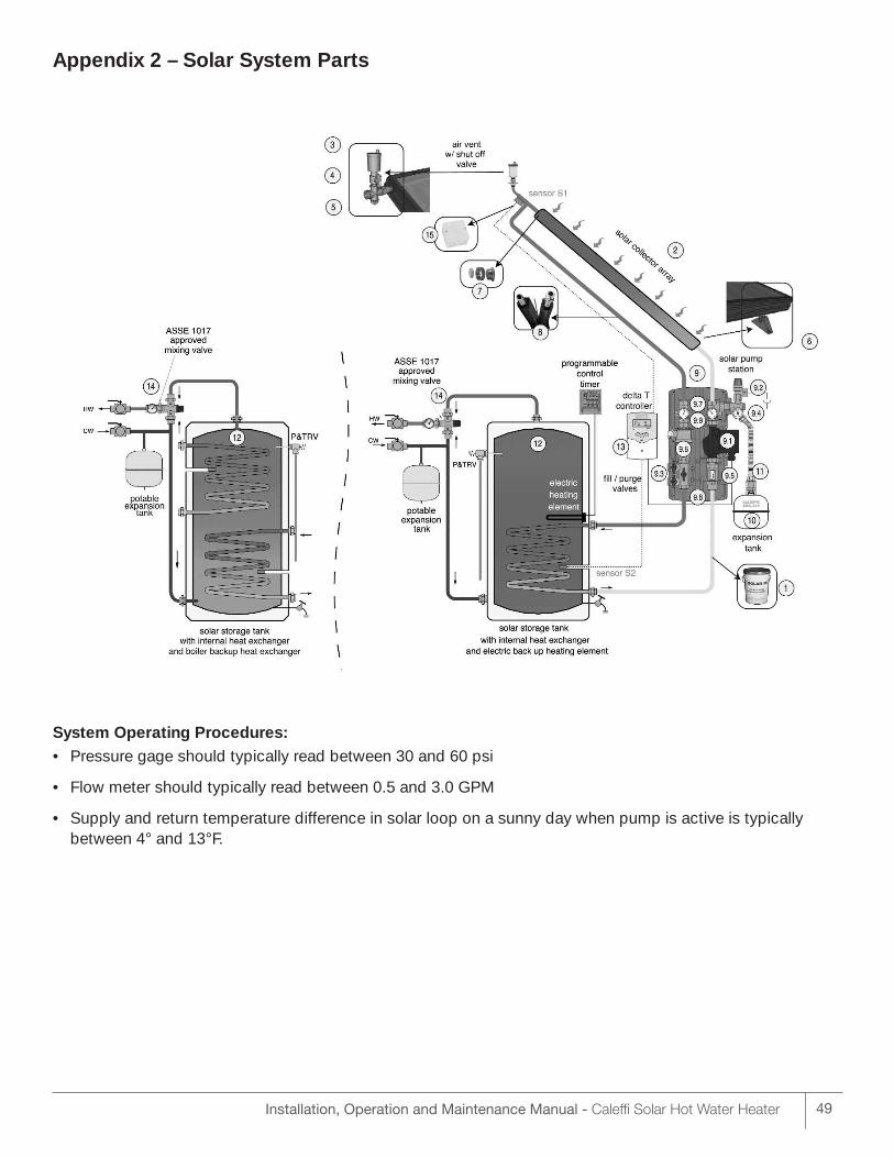
Appendix 2 – Solar System Parts
System Operating Procedures:• Pressure gage should typically read between 30 and 60 psi
• Flow meter should typically read between 0.5 and 3.0 GPM
• Supply and return temperature difference in solar loop on a sunny day when pump is active is typically between 4° and 13°F.
Installation, Operation and Maintenance Manual - Caleffi Solar Hot Water Heater50
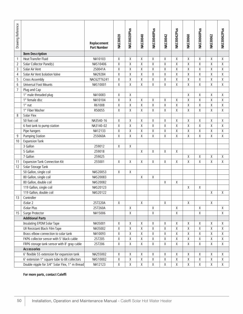
Item Description1 Heat Transfer Fluid NA10103 X X X X X X X X X X
2 Solar Collector Panel(s) NAS10406 X X X X X X X X X X
3 Solar Air Vent 250041A X X X X X X X X X X
4 Solar Air Vent Isolation Valve NA29284 X X X X X X X X X X
5 Cross Assembly NAC62TT6241 X X X X X X X X X X
6 Universal Foot Mounts NAS10001 X X X X X X X X X X
7 Plug and Cap
1" male threaded plug NA10083 X X X X X X
1" female disc NA10104 X X X X X X X X X X
1" nut R61008 X X X X X X X X X X
1" Fiber Washer R50055 X X X X X X X X X X
8 Solar Flex
50 foot coil NA3540-16 X X X X X X X X X X
6 foot tank to pump station NA3140-02 X X X X X X X X X X
Pipe hangers NA12133 X X X X X X X X X X
9 Pumping Station 255060A X X X X X X X X X X
10 Expansion Tank
3 Gallon 259012 X X
5 Gallon 259018 X X X X
7 Gallon 259025 X X X X
11 Expansion Tank Connection Kit 255001 X X X X X X X X X X
12 Solar Storage Tank
50 Gallon, single coil NAS20053 X X
80 Gallon, single coil NAS20083 X X
80 Gallon, double coil NAS20082 X X
119 Gallon, single coil NAS20123 X X
119 Gallon, double coil NAS20122 X X
13 Controller
iSolar 2 257220A X X X X X
iSolar Plus 257260A X X X X X
15 Surge Protector NA15006 X X X X X
Additional PartsInsulating EPDM Solar Tape NA35001 X X X X X X X X X X
UV Resistant Black Film Tape NA35002 X X X X X X X X X X
Brass elbow connection to solar tank NA10093 X X X X X X X X X X
FKP6 collector sensor with 5' black cable 257205 X X X X X X X X X X
FRP6 storage tank sensor with 8' gray cable 257206 X X X X X X X X X X
Accessories6' flexible SS extension for expansion tank NA255002 X X X X X X X X X X
6' extension 1" square tube to tilt collectors NAS10002 X X X X X X X X X X
Double nipple for 3/4" Solar Flex, 1" m thread NA12123 X X X X X X X X X X
For more parts, contact Caleffi
Draw
ing
Refe
renc
e
ReplacementPart Number NA
S300
20
NAS3
0020
Plus
NAS3
0040
NAS3
0040
Plus
NAS3
0042
NAS3
0042
Plus
NAS3
0060
NAS3
0060
Plus
NAS3
0062
NAS3
0062
Plus
Installation, Operation and Maintenance Manual - Caleffi Solar Hot Water Heater 51
Appendix 3 – Warranty
LIMITED WARRANTY Caleffi North America
Solar System Components
Caleffi North America (CNA) warrants to its “Customers” that all CNA products sold in accordance withthese warranty provisions shall be free from defects in material and workmanship, or other malfunction orfailure to perform, under normal use and services. “Customer” as used herein shall mean an end-user ofCNA products. This warranty is valid for the time listed below from the date of manufacture by productclassification listed below:
CNA’s sole obligation hereunder shall be, at its option, to issue credit, repair or replace any componentwhich is proved to be defective. This limited warranty does not cover the cost of transportation or laborcharges, including installation and removal, unless such charges are authorized in writing in advance byCNA. The solar antifreeze and heat transfer fluid, and maintenance schedule, must be per Caleffi systemspecification. Specifically excluded from this warranty are glass breakage and the effects of frost or acts ofGod (force majeure) responsible for system or component malfunction. Caleffi is not responsible for systemmalfunction resulting from any unauthorized alterations made to the collector panel or any Caleffi systemcomponents. Caleffi assumes no responsibility for damage to any solar system component caused by neglect, abuse, faulty installation, misuse, handling or cause not in Caleffi control or not an inherent defect.Caleffi is not liable for consequential damage or expenses, the total liability shall be limited to replacementand repair as stated above.
Disclaimer of Warranties: CALEFFI NORTH AMERICA (CNA) DISCLAIMS ANY WARRANTY NOT PROVIDED HEREIN INCLUDINGTHE IMPLIED WARRANTY OF MERCHANTABILITY AND IMPLIED WARRANTY OF FITNESS FOR A PARTICULAR PURPOSE. IT IS EXPRESSLY UNDERSTOOD THAT CNA IS NOT RESPONSIBLE FOR ANYCONSEQUENTIAL OR OTHER DAMAGES THAT MAY ARISE FROM USING CNA SYSTEM COMPONENTS.DAMAGE RESULTING FROM WATER FREEZING IN THE TUBING DOES NOT CONSTITUTE A DEFECT INMATERIAL OR WORKMANSHIP, AND SHALL NOT BE COVERED BY THIS WARRANTY. CNA DISCLAIMESANY STATUTORY OR IMPLIED WARRANTY OF HABITABILITY. CNA FURTHER DISCLAIMES ANY RESPONSIBILTY FOR LOSSES, EXPENSES, INCONVENIENCES, SPECIAL, INDIRECT, SECONDARY, INCIDENTAL, OR CONSEQUENTIAL DAMAGES ARISING FROM OWNERSHIP OR USE OF THE ARTICLESSOLD HEREUNDER. THERE ARE NO WARRANTIES WHICH EXTEND BEYOND THE FACE HEREOF.