42
Installation, Operation and Maintenance Manual Voice Messaging Unit VMU-IOM-01 Rev 1.0
Installation, Operation and Maintenance Manual
Voice Messaging Unit
VMU-IOM-01
Rev 1.0


Installation, Operation and Maintenance Manual
Voice Messaging Unit (VMU)
VMU-IOM-01Rev 1.0

Copyright © 2006 OuterLink Corporation All rights reserved. No part of this documentation may be reproduced in any form or by any means or used to make any derivative work (such as translation, transformation, or adaptation) without written permission from OuterLink Corporation.OuterLink reserves the right to revise this documentation and to make any changes in content from time to time without obligation on the part of OuterLink Corporation to provide notification of such revision or change. OuterLink Corporation provides this documentation without warranty, term, or condition of any kind, either implied or expressed, including, but not limited to, the implied warranties, terms or conditions of merchantability, satisfactory quality, and fitness for a particular purpose. OuterLink Corporation may make improvements or changes in the product(s) and/or the program(s) described in this documentation at any time.The OuterLink logo is a servicemark of OuterLink Corporation. All other product or service names are the property of their respective owners.

CONTENTS
PrefaceUsing OuterLink Electronic Documents . . . . . . . . . . . . . . . . . . . . . . . . . . . . . . . . xiiGuide Conventions . . . . . . . . . . . . . . . . . . . . . . . . . . . . . . . . . . . . . . . . . . . . . . . . xiiiRelated Product Documentation . . . . . . . . . . . . . . . . . . . . . . . . . . . . . . . . . . . . . . xivRevision History . . . . . . . . . . . . . . . . . . . . . . . . . . . . . . . . . . . . . . . . . . . . . . . . . . xv
Chapter 1 IntroductionVMU Overview . . . . . . . . . . . . . . . . . . . . . . . . . . . . . . . . . . . . . . . . . . . . . . . . . . . . 2
VMU Controls . . . . . . . . . . . . . . . . . . . . . . . . . . . . . . . . . . . . . . . . . . . . . . . . . . . 2
Chapter 2 InstallationInstalling the VMU . . . . . . . . . . . . . . . . . . . . . . . . . . . . . . . . . . . . . . . . . . . . . . . . . . 6
Connecting the VMU to the CP-4i . . . . . . . . . . . . . . . . . . . . . . . . . . . . . . . . . . . . 6Mounting the VMU . . . . . . . . . . . . . . . . . . . . . . . . . . . . . . . . . . . . . . . . . . . . . . . 8VMU Test and
Checkout Procedure . . . . . . . . . . . . . . . . . . . . . . . . . . . . . . . . . . . . . . . . . . . . 9Power Up Test Procedure . . . . . . . . . . . . . . . . . . . . . . . . . . . . . . . . . . . . . . 9Mayday Test Procedure . . . . . . . . . . . . . . . . . . . . . . . . . . . . . . . . . . . . . . . . 9Send Voice Message Test Procedure . . . . . . . . . . . . . . . . . . . . . . . . . . . . . 9Receive Voice Message Test Procedure . . . . . . . . . . . . . . . . . . . . . . . . . . . 9
Chapter 3 OperationOperations of the VMU . . . . . . . . . . . . . . . . . . . . . . . . . . . . . . . . . . . . . . . . . . . . . 12
Power Up Operation . . . . . . . . . . . . . . . . . . . . . . . . . . . . . . . . . . . . . . . . . . . . . 12Two-way Voice
Messaging Operation . . . . . . . . . . . . . . . . . . . . . . . . . . . . . . . . . . . . . . . . . . . 12Sending a Voice Message . . . . . . . . . . . . . . . . . . . . . . . . . . . . . . . . . . . . . 12Receiving a Voice Message . . . . . . . . . . . . . . . . . . . . . . . . . . . . . . . . . . . . 12
Mayday Operation . . . . . . . . . . . . . . . . . . . . . . . . . . . . . . . . . . . . . . . . . . . . . . 12Standby Mode . . . . . . . . . . . . . . . . . . . . . . . . . . . . . . . . . . . . . . . . . . . . . . . . . . 13
Chapter 4 MaintenanceMaintaining the VMU . . . . . . . . . . . . . . . . . . . . . . . . . . . . . . . . . . . . . . . . . . . . . . . 16
Inspection of the VMU . . . . . . . . . . . . . . . . . . . . . . . . . . . . . . . . . . . . . . . . . . . 16Troubleshooting the VMU . . . . . . . . . . . . . . . . . . . . . . . . . . . . . . . . . . . . . . . . . . . 17
Appendix A SpecificationsVMU Specifications . . . . . . . . . . . . . . . . . . . . . . . . . . . . . . . . . . . . . . . . . . . . . . . . 20Agency Approvals . . . . . . . . . . . . . . . . . . . . . . . . . . . . . . . . . . . . . . . . . . . . . . . . . 21Technical Support . . . . . . . . . . . . . . . . . . . . . . . . . . . . . . . . . . . . . . . . . . . . . . . . . 22
Index . . . . . . . . . . . . . . . . . . . . . . . . . . . . . . . . . . . . . . . . . . . . . . . . . . . . . . . . . . . 23
VMU Installation, Operation and Maintenance Manual v

Contents
vi VMU Installation, Operation and Maintenance Manual.

LIST OF FIGURES
1 VMU Talk/Listen Connections. . . . . . . . . . . . . . . . . . . . . . . . . . . . . . . . . . . . 22 VMU Controls . . . . . . . . . . . . . . . . . . . . . . . . . . . . . . . . . . . . . . . . . . . . . . . . 23 VMU Rear Panel . . . . . . . . . . . . . . . . . . . . . . . . . . . . . . . . . . . . . . . . . . . . . . 64 VMU Outline Drawing . . . . . . . . . . . . . . . . . . . . . . . . . . . . . . . . . . . . . . . . . . 85 VMU Front Panel and Dzus Fasteners . . . . . . . . . . . . . . . . . . . . . . . . . . . . . 86 VMU Front Panel. . . . . . . . . . . . . . . . . . . . . . . . . . . . . . . . . . . . . . . . . . . . . 12
VMU Installation, Operation and Maintenance Manual vii

List of Figures
viii VMU Installation, Operation and Maintenance Manual

LIST OF TABLES
1 Navigating Within a PDF Document . . . . . . . . . . . . . . . . . . . . . . . . . . . . . . xii2 OuterLink Documentation Set . . . . . . . . . . . . . . . . . . . . . . . . . . . . . . . . . . xiv3 VMU Installation, Operation and Maintenance Manual Revision History . . xv4 VMU Controls . . . . . . . . . . . . . . . . . . . . . . . . . . . . . . . . . . . . . . . . . . . . . . . . 35 VMU 9-Pin D-Type Serial Connector (Port 1). . . . . . . . . . . . . . . . . . . . . . . . 66 VMU 9-Pin D-Type Serial Connector (Port 2) . . . . . . . . . . . . . . . . . . . . . . . . 77 VMU 5-Pin Audio Connector . . . . . . . . . . . . . . . . . . . . . . . . . . . . . . . . . . . . . 78 Troubleshooting Matrix . . . . . . . . . . . . . . . . . . . . . . . . . . . . . . . . . . . . . . . . 179 VMU Specifications . . . . . . . . . . . . . . . . . . . . . . . . . . . . . . . . . . . . . . . . . . . 2010 VMU Agency Approvals . . . . . . . . . . . . . . . . . . . . . . . . . . . . . . . . . . . . . . . 21
VMU Installation, Operation and Maintenance Manual ix

List of Tables
x VMU Installation, Operation and Maintenance Manual

Preface
This manual provides information about the OuterLink Voice Messaging Unit (VMU). It is written to support the VMU user and installer. The manual is divided into the following topics:
� Introduction � Installation � Operation � Maintenance � Specifications
VMU Installation, Operation and Maintenance Manual xi

Preface
Using OuterLink Electronic Documents
OuterLink Corporation electronic documents are provided as PDF files. Open and view them using the Adobe® Acrobat® Reader application, version 3.0 or later. If nec-essary, download the Acrobat Reader from the Adobe Systems, Inc. web site:
http://www.adobe.com/prodindex/acrobat/readstep.html
Each provided PDF file offers several ways for moving among the document�s pages, as follows:
To move quickly from section to section within the document, use the Acrobat book-marks that appear on the left side of the Acrobat Reader window. The bookmarks pro-vide an expandable outline view of the document�s contents. To display the document�s Acrobat bookmarks, press the �Display both bookmarks and page� button on the Acrobat Reader tool bar.
To move to the referenced page of an entry in the document�s Contents or Index, click on the entry itself, each of which is hyperlinked.
To follow a cross-reference to a heading, figure, or table, click the blue text.
To move to the beginning or end of the document, to move page by page within the document, or to navigate among the pages you displayed by clicking on hyperlinks, use the Acrobat Reader navigation buttons shown in this figure:
Table 1 summarizes how to navigate within a OuterLink Corporation electronic docu-ment.
Table 1 Navigating Within a PDF Document
To Navigate This Way Click This
Move from section to section within the document.
A bookmark on the left side of the Acrobat Reader window.
Move to an entry in the Table of Contents.
The entry itself.
Move to an entry in the Index. The page number.
Move to an entry in the List of Figures or List of Tables.
The Figure or Table number.
Follow a cross-reference(highlighted in blue text).
The cross-reference text.
Move page by page. The appropriate Acrobat Reader navigationbuttons.
Move to the beginning or end of the document.
The appropriate Acrobat Reader navigation buttons.
Move backward or forward among a series of hyperlinks you have selected.
The appropriate Acrobat Reader navigation buttons.
Beginning of document End of document
Next pagePrevious page
Previous or next hyperlink
xii VMU Installation, Operation and Maintenance Manual

Preface
Guide Conventions The following visual elements are used throughout this manual, where applicable:
WARNING: Provide information that can help prevent potential fatal or serious injury to a user.
CAUTION: Provide information that can help prevent damage to equipment or the environment.
NOTE: Provide information of special importance.
VMU Installation, Operation and Maintenance Manual xiii

Preface
Related Product Documentation
Table 2 lists the OuterLink documentation set.
Table 2 OuterLink Documentation Set
Document Name Purpose Document Number
CommTrack Suite 2007 User Manual
Describes the basic use and operation of the OuterLink software suite including: • CommTrack (graphical display) • CommText (text display) • CommFigure (mission analysis) • CommSpeak (voice/text display)CommSpeak Hub (interface to CommCenter, track and voice data-bases).
CTS-UM
CommTrack Suite 2007 Installation Manual
Provides instructions for the installation of the CommTrack software suite.
CTS-IM
CommCenter User Manual Provides instructions for the installation of the CommCenter software suite.
CC-UM
CP-3i Installation, Operation and Maintenance Manual
Provides instructions for the installation, operation and maintenance of the CP-3i hardware.
CP3i-IOM-AC
CP-4i Installation, Operation and Maintenance Manual
Provides instructions for the installation, operation and maintenance of the CP-4i hardware.
CP4i-IOM-VE
CDU Installation, Operation and Maintenance Manual
Describes the installation, operation and maintenance of the Control Display Unit (CDU).
CDU-IOM-02
OCP Installation, Operation and Maintenance Manual
Describes the installation, operation and maintenance of the OuterLink COntrol Panel (OCP).
OCP-IOM-01
OVP Installation, Operation and Maintenance Manual
Describes the installation, operation and maintenance of the OuterLink Voice Panel (OVP.)
OVP-IOM-01
VMU Installation, Operation and Maintenance Manual
Describes the installation, operation and maintenance of the Voice Messaging Unit (VMU).
VMU-IOM-01
KDU Installation, Operation and Maintenance Manual
Describes the installation, operation and maintenance of the Key-board Display Unit (KDU).
KDU-IOM-01
xiv VMU Installation, Operation and Maintenance Manual
Preface
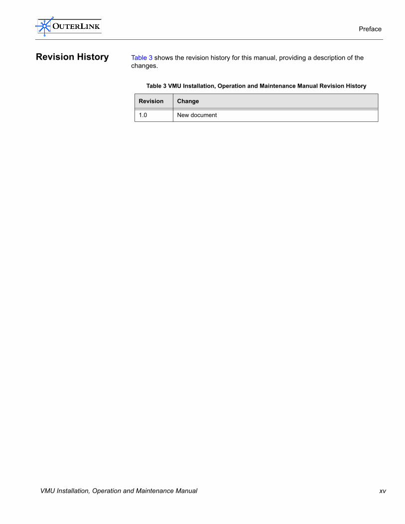
Revision History Table 3 shows the revision history for this manual, providing a description of the changes.
Table 3 VMU Installation, Operation and Maintenance Manual Revision History
Revision Change
1.0 New document
VMU Installation, Operation and Maintenance Manual xv

Preface
xvi VMU Installation, Operation and Maintenance Manual

Chapter 1
Introduction
This chapter provides an introduction to the OuterLink Voice Messaging Unit (VMU). The following topics are covered:
� VMU Overview � VMU Controls
VMU Installation, Operation and Maintenance Manual 1
Introduction
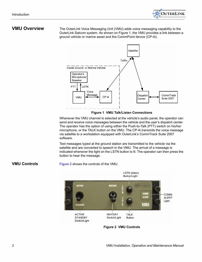
VMU Overview The OuterLink Voice Messaging Unit (VMU) adds voice messaging capability to the OuterLink Satcom system. As shown on Figure 1, the VMU provides a link between a ground vehicle or marine asset and the CommPoint device (CP-4i).
Figure 1 VMU Talk/Listen ConnectionsWhenever the VMU channel is selected at the vehicle�s audio panel, the operator can send and receive voice messages between the vehicle and the user�s dispatch center. The operator has the option of using either the Push-to-Talk (PTT) switch on his/her microphone, or the TALK button on the VMU. The CP-4i transmits the voice message via satellite to a workstation equipped with OuterLink�s CommTrack Suite 2007software.
Text messages typed at the ground station are transmitted to the vehicle via thesatellite and are converted to speech in the VMU. The arrival of a message is indicated whenever the light on the LSTN button is lit. The operator can then press the button to hear the message.
VMU Controls Figure 2 shows the controls of the VMU.
Figure 2 VMU Controls
2 VMU Installation, Operation and Maintenance Manual

Introduction
Table 4 describes the basic function of each button and the VMU. Refer to �Operations of the VMU� on page 12 for button operations.
Table 4 VMU Controls
Item Function
ACTIVE/STANDBY Switch / Light
Used to put the VMU in active (on) or standby (off) modes. Backlight turns GREEN on power up.
MAYDAY Switch / Light
Used to activate/deactivate an emergency message. In M-DAY ON position, backlight turns AMBER when activated and turns GREEN when �MAYDAY ACK� is received from Base Station.
LSTN Button/Light Lights amber indicating a voice message is available from the control center. Pressing the button plays the last message received and turns light off.
TALK Button Press to speak and send resulting message to base station.
COMM ALERT Light
At start-up, lights amber if no connection is made to CP-4i. During operation, lights amber indicating that a �MAYDAY� message has not been �ACK�ed by the Base Station.
VMU Installation, Operation and Maintenance Manual 3

Introduction
4 VMU Installation, Operation and Maintenance Manual

Chapter 2
This chapter provides information on installation of the VMU. The following topics are covered:
� Installing the VMU � Connecting the VMU to the CP-4i
� Mounting the VMU � VMU Test and Checkout Procedure
� Power Up Test Procedure � Mayday Test Procedure � Send Voice Message Test Procedure � Receive Voice Message Test Procedure
Installation
VMU Installation, Operation and Maintenance Manual 5

Installation
Installing the VMU This section covers the installation of the VMU.
CAUTION: The VMU is designed for 12-28 VDC, negative ground systems only. Use with any other type of electrical system may damage the unit and void the warranty.
This installation procedure assumes that a mounting location for the VMU exists in the vehicle. Ensure that adequate space exists to route and neatly secure all cables, with adequate service loops for stress relief at connectors.
The location of the connectors on the rear of the VMU are shown on Figure 3. An outline drawing of the VMU with dimensions is shown in Figure 4. Connector pin outs are shown in Tables 5,6 and 7.
Connecting the VMU to the CP-4i
Port 1 of the VMU must be wired to Port 1 of the CP-4i CommPoint Unit. A separate power cable supplies +28 VDC to the VMU.
1. Pull the CP-4i interface cable out through the console mounting bezel for the VMU.
2. Connect and tighten the cable�s 9-pin connector to Port 1 on the rear of the VMU. Power is applied to the unit through pins 6-9 of this connector.
Figure 3 VMU Rear Panel
Table 5 VMU 9-Pin D-Type Serial Connector (Port 1).
Pin Name
1 EXT MSG
2 RxD (IN)
3 TxD (OUT)
4 DIM IN
5 GND
6 +28VDC POWER INPUT
7 +28VDC POWER INPUT
8 POWER GND
9 POWER GND
6 VMU Installation, Operation and Maintenance Manual
Installation
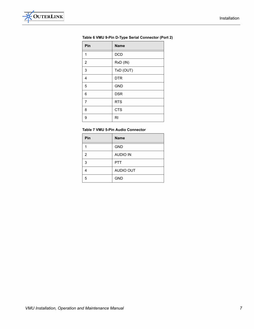
Table 6 VMU 9-Pin D-Type Serial Connector (Port 2)
Table 7 VMU 5-Pin Audio Connector
Pin Name
1 DCD
2 RxD (IN)
3 TxD (OUT)
4 DTR
5 GND
6 DSR
7 RTS
8 CTS
9 RI
Pin Name
1 GND
2 AUDIO IN
3 PTT
4 AUDIO OUT
5 GND
VMU Installation, Operation and Maintenance Manual 7
Installation
Mounting the VMU To mount the VMU in the vehicle�s control console proceed as follows:
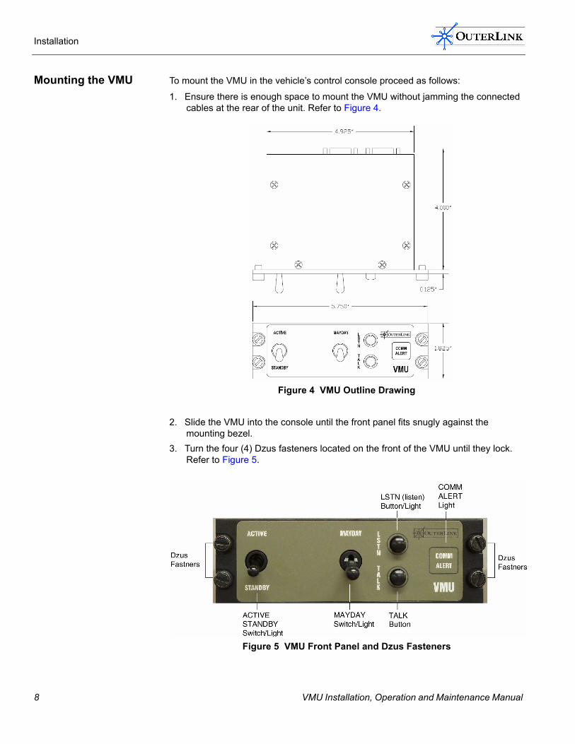
1. Ensure there is enough space to mount the VMU without jamming the connected cables at the rear of the unit. Refer to Figure 4.
Figure 4 VMU Outline Drawing
2. Slide the VMU into the console until the front panel fits snugly against the mounting bezel.
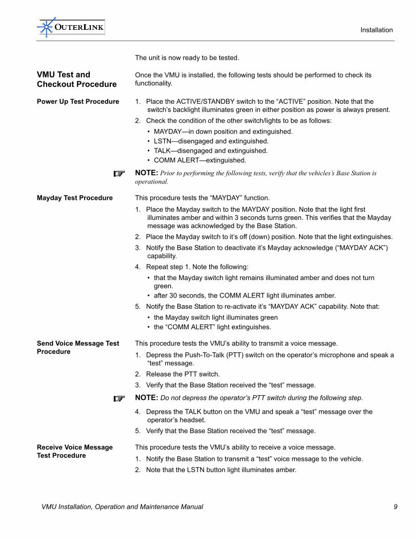
3. Turn the four (4) Dzus fasteners located on the front of the VMU until they lock. Refer to Figure 5.
Figure 5 VMU Front Panel and Dzus Fasteners
8 VMU Installation, Operation and Maintenance Manual
Installation
The unit is now ready to be tested.
VMU Test and Checkout Procedure
Once the VMU is installed, the following tests should be performed to check its functionality.
Power Up Test Procedure 1. Place the ACTIVE/STANDBY switch to the �ACTIVE� position. Note that the switch�s backlight illuminates green in either position as power is always present.
2. Check the condition of the other switch/lights to be as follows:� MAYDAY�in down position and extinguished.� LSTN�disengaged and extinguished.� TALK�disengaged and extinguished.� COMM ALERT�extinguished.
NOTE: Prior to performing the following tests, verify that the vehicles�s Base Station is operational.
Mayday Test Procedure This procedure tests the �MAYDAY� function.
1. Place the Mayday switch to the MAYDAY position. Note that the light first illuminates amber and within 3 seconds turns green. This verifies that the Mayday message was acknowledged by the Base Station.
2. Place the Mayday switch to it�s off (down) position. Note that the light extinguishes.3. Notify the Base Station to deactivate it�s Mayday acknowledge (�MAYDAY ACK�)
capability.4. Repeat step 1. Note the following:
� that the Mayday switch light remains illuminated amber and does not turn green.
� after 30 seconds, the COMM ALERT light illuminates amber.5. Notify the Base Station to re-activate it�s �MAYDAY ACK� capability. Note that:
� the Mayday switch light illuminates green� the �COMM ALERT� light extinguishes.
Send Voice Message Test Procedure
This procedure tests the VMU�s ability to transmit a voice message.
1. Depress the Push-To-Talk (PTT) switch on the operator�s microphone and speak a �test� message.
2. Release the PTT switch.3. Verify that the Base Station received the �test� message.
NOTE: Do not depress the operator�s PTT switch during the following step.
4. Depress the TALK button on the VMU and speak a �test� message over theoperator�s headset.
5. Verify that the Base Station received the �test� message.
Receive Voice Message Test Procedure
This procedure tests the VMU�s ability to receive a voice message.
1. Notify the Base Station to transmit a �test� voice message to the vehicle.2. Note that the LSTN button light illuminates amber.
VMU Installation, Operation and Maintenance Manual 9

Installation
3. Depress the LSTN button and note that the �test� voice message is heard on the operator�s speaker.
4. Note that the LSTN button light extinguishes when depressed.
10 VMU Installation, Operation and Maintenance Manual

Chapter 3
This chapter provides information on using the VMU. The following topics are covered:
� Operations of the VMU � Power Up Operation � Two-way Voice Messaging Operation � Mayday Operation � Standby Mode
Operation
VMU Installation, Operation and Maintenance Manual 11

Operation
Operations of the VMU
The various operational modes of the VMU are described in this section. Figure 6 shows the front panel of the VMU. The switches, buttons and their associated lights are used to perform the operational modes.
Figure 6 VMU Front Panel
Power Up Operation Connect power to the VMU. Toggle the ACTIVE/STANDBY switch to the ACTIVE position to change the VMU from standby to active mode. The switch�s backlight illu-minates green.
Two-way VoiceMessaging Operation
Two-way voice messaging may be conducted between the vehicle�s VMU Voice Panel and the Base Station�s CommSpeak software. The VMU contains both TALK and LSTN (listen) message selections. Voice messages from the vehicle are transmitted via satellite to the Base Station where they are displayed by the CommSpeak pro-gram. The Base Station transmits text messages via the satellite to the vehicle where they are converted to speech by the VMU.
Sending a Voice Message The operator can send a voice message in one of two ways:
� Use the Push-To-Talk (PTT) switch on his/her microphone.� Use the TALK button on the VMU.
To send a voice message, follow these steps:
1. Press and hold the microphone�s PTT switch, or the TALK button on the VMU.2. Speak your message.3. Release the button.
Receiving a Voice Message The operator is notified that a message has been received from the Base Station whenever the VMU�s LSTN button illuminates.
To receive a voice message, follow these steps:
1. Note that the LSTN button light is illuminated amber.2. Press the LSTN button on the VMU to hear the message.The most recent message received will be played first.
Mayday Operation In the event of an emergency, the operator can activate the Mayday function from the VMU by flipping the Mayday switch to the MAYDAY position.This automatically
12 VMU Installation, Operation and Maintenance Manual

Operation
transmits a �MAYDAY� message, including GPS location data, every 3 seconds to the Base Station. The Base Station then acknowledges the receipt of the �MAYDAY� message by sending a �MAYDAY ACK� message back to the vehicle. The sequence of events is described below:
NOTE: This Mayday procedure should be used, if possible, to augment your standard emergency procedures, not in place of such procedures. In particular, do NOT assume that the �MAYDAY� message has been visually acknowledged by Base Station operations. Continue to follow all standard Emergency procedures, including using voice communications as the primary mode of communications.
� The operator toggles the pull-lock Mayday switch to the MAYDAY position. The switch�s light illuminates amber.
� The �MAYDAY� message begins transmitting every 3 seconds together with GPS location data, which is continuously updated.
� Receipt of a �MAYDAY� message at the Base Station triggers an alarm thatindicates a Mayday situation and identifies the vehicle by it�s ID. A �MAYDAY ACK� message is automatically generated and transmitted back to the vehicle.
� Upon receipt of the �MAYDAY ACK� message, the VMU�s Mayday switch light changes from amber to green. The VMU will remain in the Mayday state until the Mayday switch is returned to it�s off (down) position.
NOTE: The VMU will continue to transmit the "MAYDAY" message every 3 seconds until it receives back the �MAYDAY ACK� message. If after several retries the �MAYDAY ACK� message is still not received, the COMM ALERT light will illuminate.
Standby Mode To place the VMU in the standby mode, toggle the ACTIVE/STANDBY switch to the STANDBY position. This has no effect on the operation of the CP-4i.
VMU Installation, Operation and Maintenance Manual 13
Operation
14 VMU Installation, Operation and Maintenance Manual

Chapter 4
This chapter provides information on maintaining the VMU. The following topics are covered:
� Maintaining the VMU � Troubleshooting the VMU
Maintenance
VMU Installation, Operation and Maintenance Manual 15

Maintenance
Maintaining the VMU
Maintenance of the VMU is limited to periodic inspection as described below.
Inspection of the VMU The VMU should be inspected on a routine schedule to ensure that:
� All fasteners and cable connections are tightened properly.� Switches and buttons are operational and not broken.
If you encounter an issue with the switches or buttons, please contact Technical Support (refer to �Technical Support� on page 22).
16 VMU Installation, Operation and Maintenance Manual

Maintenance
Troubleshooting the VMU
Table 8 provides a guide to troubleshooting the VMU.
NOTE: A Digital Multimeter is recommended to assist you in troubleshooting.
Table 8 Troubleshooting Matrix
Symptom Possible Causes Solution
No power when the ACTIVE/STANDBY switch is positioned to ACTIVE.
No power in aircraft. Check for blown or removed fuses.
Electrical bus not turned on. Turn on the bus.
Bad power switch. Check the power switch for functionality.
Faulty wiring Meter the wiring
Mayday switch light does not illuminate when the switch is positioned to MAY-DAY.
No power Check �No power� symptoms (above)
Faulty switch light Replace switch
No �MAYDAY� mes-sage sent when the Mayday switch is positioned to MAY-DAY.
Faulty Switch Replace switch
Bad VMU cable connections, or ground Inspect VMU cable, connections, and ground wire.
Faulty CP-4i Comm Point unit Replace CP-4i Comm Point Unit
Faulty VMU Replace VMU
Mayday switch light does not change from amber to green when the switch is in the MAYDAY posi-tion and a �MAYDAY ACK� message is received
Faulty switch light Replace switch
Bad VMU cable connections, or ground Inspect VMU cable, connections, and ground wire.
Faulty CP-4i Comm Point unit Replace CP-4i Comm Point unit
Faulty VMU Replace VMU
The TALK button light does not illumi-nate when the TALK button is depressed.
No power Check �No power� symptoms (above)
Faulty button light Replace button
VMU Installation, Operation and Maintenance Manual 17

Maintenance
No voice message sent when TALK button is depressed and pilot speaks.
Vehicle�s audio distribution panel Check that the VMU channel is selected.
Faulty headset Replace headset
Faulty TALK button Replace button
Bad VMU cable connections, or ground Inspect VMU cable, connections, and ground wire.
Faulty CP-4i Comm Point Unit Replace CP-4i Comm Point Unit
Faulty VMU Replace VMU
The LSTN button light does not illumi-nate when a voice message is received.
No power Check �No power� symptoms (above)
Faulty button light Replace button
Bad VMU cable connections, or ground Inspect VMU cable, connections, and ground wire.
Faulty CP-4i Comm Point Unit Replace CP-4i Comm Point Unit
No voice message heard when LSTN button is illuminated & the button is depressed.
Vehicle�s audio distribution panel Check that the VMU channel is selected.
Faulty headset Replace headset
The COMM ALERT light does not illumi-nate when MAY-DAY ACK� message is deactivated.
No power Check �No power� symptoms (above)
Faulty light Replace light
Bad VMU cable connections, or ground Inspect VMU cable, connections, and ground wire.
Faulty CP-4i Comm Point Unit Replace CP-4i Comm Point Unit
Table 8 Troubleshooting Matrix (continued)
Symptom Possible Causes Solution
18 VMU Installation, Operation and Maintenance Manual
Appendix A
This appendix provides information on the specifications and contacting technical support for the VMU. The following topics are covered:
� VMU Specifications � Agency Approvals � Technical Support
Specifications
VMU Installation, Operation and Maintenance Manual 19

Specifications
VMU Specifications
The technical specifications for the VMU are listed in Table 9.
Table 9 VMU Specifications
Category Specification
Dimensions 5.75"W x 4.00" D x 1.83" H (14.6 cm x 10.2 cm x 4.6 cm)
Weight 18.1 oz (513 g)
Power 12 � 28VDC; pins 6-9 of Serial Port 1
I/O
Serial Port 1 RS-232, 9-pin D-Type, Socket 9600 BAUD, "N-8-1" , 3-wire (TX, RX, GND)
Serial Port 2 RS-232, 9-pin D-Type, Pin 9600 BAUD, "N-8-1" , 3-wire (TX, RX, GND)
Ethernet RJ-45, 10/100 BaseT
Audio 5-pin, Switchcraft Tini Q-G Connector, Pin
Mounting Dzus
Connector 9-Pin �D� type
Environmental
Operating Temperature -40° � 70°C
Storage Temperature -40° � 85°C
Relative Humidity 10 � 90% non-condensing
Altitude 25,000 Ft. (7620m) (Unpressurized)
20 VMU Installation, Operation and Maintenance Manual

Specifications
Agency Approvals Agency approvals for the VMU are listed in Table 10
Table 10 VMU Agency Approvals
Agency Standard Description
FCC FCC CFR 47 Parts 87, Subsection D, and Technical Requirements.
FCC CFR 47, Part 15, Radio Frequency Devices, Sub-section B and Unintentional Radiators.
FCC Parts 15 and 2 Subsection I and J.
VMU Installation, Operation and Maintenance Manual 21

Specifications
Technical Support For additional assistance, please contact OuterLink Technical Support.
� Call us at: 978-856-0007� Fax us at: 978-856-0013� Email us at: [email protected]
22 VMU Installation, Operation and Maintenance Manual

INDEX
A
Acrobat bookmarks xiiACTIVE/STANDBY Switch Light 3Adobe® Acrobat® Reader xiiAgency Approvals 21
B
bookmarks xiibuttons
LSTN 2, 9, 12, 18TALK 2, 9, 12, 17
C
COMM ALERT Light 3, 9, 13, 18CommSpeak software 12Contact Information
Technical Support 22controls of the VMU 2CP-4i 2, 2, 6, 13, 18
D
Dzus fasterners 8
E
electronic documents xii
F
front panel 9, 12
G
Guide Conventions xiii
I
Inspection of the VMU 16Installing the VMU 6
L
LSTN button 3, 10, 12
VMU Installation, Operation and Maintenance Manual
MMaintenance of the VMU 16Manual Overview xiMayday
message 13Operation 12switch/light 3, 17test procedure 9
MAYDAY ACK acknowledge 9, 13Mayday Switch / Light 13Mounting the VMU 8
Ooperational modes 12OuterLink documentation set xiv
PPort 1 6Power Up
Operation 12Push-to-Talk (PTT) switch 2, 9, 12
Rrear panel connectors 6Receive Voice Message Test Procedure 9Receiving a Voice Message 12Related Product Documentation xivRevision history, for this manual xv
SSend Voice Message Test Procedure 9Sending a Voice Message 12Shutdown Operation 13
TTALK button 3, 12Talk/Listen Connections 2Technical Support
Contact Information 22Technical Writing by
www.cedarwoodassociates.com iv
23

Index
Text messages 2Troubleshooting the VMU 17Two-way Voice Messaging Operation 12
UUsing OuterLink Electronic Documents xii
VVMU
agency approvals 21connecting 6controls 2front panel 2inspection 16maintenance 16operation 11, 12outline drawing 8power down 13rear panel 6specifcations 20test and checkout procedure 9Troubleshooting 17
VMU channel 2
24
VMU Installation, Operation and Maintenance Manual

OuterLink Corporation175 Cabot Street, Suite 311, Lowell, MA 01854 Voice: 978.856.0007 Fax: 978.856.0013

![Watchman Bro Nov 2016 Final - Ellipse Security, Inc.UNITEK MANAGEMENT [VMU & DHS] DHS VMU VMU FEATURES Real-time DVR monitoring Various screen division mode (single, quad, 9-split,](https://static.documents.pub/doc/80x56/5f0a79707e708231d42bcffa/watchman-bro-nov-2016-final-ellipse-security-inc-unitek-management-vmu-.jpg)


![Injection System VMU plus - tapcon.com.vn VMU Plus anchor brochures (hollow)_EN_1.pdfmin,II [mm] 240 240 498 498 373 498 Min. spacing perpendicular to bearing joint s min,I [mm] 71](https://static.documents.pub/doc/80x56/5e719643e7fca7386c2d87b5/injection-system-vmu-plus-vmu-plus-anchor-brochures-hollowen1pdf-minii-mm.jpg)


