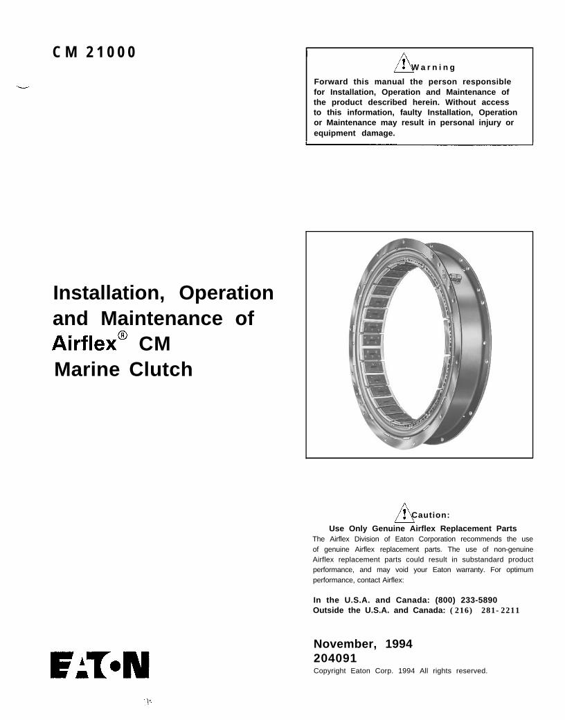
CM 21000 Warning Forward this manual the person responsible for Installation, Operation and Maintenance of the product described herein. Without access to this information, faulty Installation, Operation or Maintenance may result in personal injury or equipment damage. Installation, Operation and Maintenance of Airflex@ CM Marine Clutch n ! Caution: Use Only Genuine Airflex Replacement Parts The Airflex Division of Eaton Corporation recommends the use of genuine Airflex replacement parts. The use of non-genuine Airflex replacement parts could result in substandard product performance, and may void your Eaton warranty. For optimum performance, contact Airflex: In the U.S.A. and Canada: (800) 233-5890 Outside the U.S.A. and Canada: (216) 281-2211 November, 1994 204091 Copyright Eaton Corp. 1994 All rights reserved.
Transcript
C M 2 1 0 0 0 W a r n i n g
Forward this manual the person responsiblefor Installation, Operation and Maintenance ofthe product described herein. Without accessto this information, faulty Installation, Operationor Maintenance may result in personal injury orequipment damage.
Installation, Operationand Maintenance ofAirflex@ CM
Marine Clutch
n! Caution:
Use Only Genuine Airflex Replacement PartsThe Airflex Division of Eaton Corporation recommends the useof genuine Airflex replacement parts. The use of non-genuineAirflex replacement parts could result in substandard productperformance, and may void your Eaton warranty. For optimumperformance, contact Airflex:
In the U.S.A. and Canada: (800) 233-5890Outside the U.S.A. and Canada: (216) 281-2211
November, 1994204091Copyright Eaton Corp. 1994 All rights reserved.
8.0 ELEMENT PARTS LIST . . . . . . . . . . . . . . . . . . . . . . . . 9
Copyright Eaton Corp., 1994. All rights reserved.
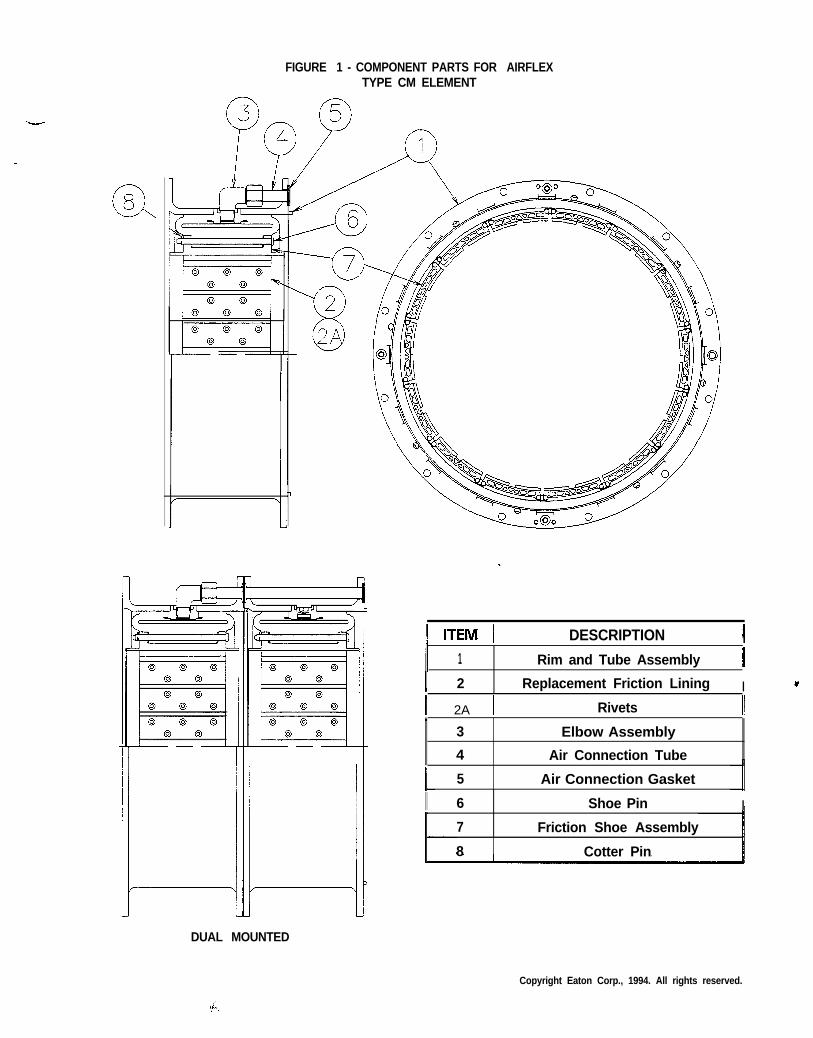
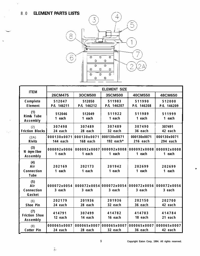
FIGURE 1 - COMPONENT PARTS FOR AIRFLEXTYPE CM ELEMENT
II n-EM I DESCRIPTION II1 Rim and Tube Assembly II
I 2 Replacement Friction Lining I
I 2A I Rivets II”
3 Elbow Assembly
4 Air Connection Tube
5 Air Connection Gasket
I I 6 Shoe Pin I
7 Friction Shoe Assembly
8 Cotter Pin
DUAL MOUNTED
Copyright Eaton Corp., 1994. All rights reserved.
1 .0 INTRODUCTION
Throughout this manual there are a numberof HAZARD WARNINGS that must be readand adhered to in order to prevent possiblepersonal injury and/or damage to the equipment.Three signal words “DANGER”, “WARNING”,and “CAUTION” are used to indicate theseverity of the hazard, and are preceded by the
safety alert symbol A.
A! DANGERDenotes the most serious injuryhazard, and is used when seriousinjury or death WILL result frommisuse or failure to follow specificinstructions.
A! WARNINGUsed when serious injury or death MAYresult from misuse or failure to followspecific instructions.
A! CAUTIONUsed when injury or product/equipmentdamage may result from misuse or failureto follow specific instructions.
1 1. Description
1 .1 .1 The Airflex air-actuated CM element assemblyis designed and manufactured to providedependable clutch service in a multitude ofmarine and industrial applications. Theventilated construction is suited for heavyduty operations where moderate slippage isencountered. All torque load is carried throughthe neoprene and cord actuating tube whichassists in absorbing damaging shock loads.The Airflex CM element assembly requires nolubrication or adjustment.
1.1.2 All Airflex CM element assemblies are suppliedwith NON-ASBESTOS friction material.
2
1.1.3
1.1.4
1.1.5
1 2.
1.2.1
1.2.2
1.2.3
The Airflex CM element assemblies areavailable in 5 sizes which are identified bythe drum diameter in inches on which theyconstrict and the width in inches of its frictionlining. For instance, size 26CM475 is designedto constrict on to a 26 inch (660 mm) diame-ter drum and has a friction lining width of 4.75inches (121 mm). The smallest CM elementwill constrict on a 26 inch (660 mm) diameterdrum and the largest on a 48 inch (1219 mm)drum.
---A--
Individual elements can be bolted together toform dual elements having twice the torquecapacity of a single element.
CM elements have gained popularity asmarine propulsion clutches. In this arrange-ment, one element of a dual mounted unitdrives through a drum and drum hub attachedto a gearbox pinion and functions as the ahead(forward) clutch, the other element drivesthrough a gear shaft drum and drum hub andspacer and functions as the astern (reverse)clutch. A manifold is bolted to the outboardend of the element to serve as an inlet for therequired air supply and connection to the en-gine flywheel.
HOW IT WORKS
Referring to Figure 1, CM constructionconsists of a neoprene and cord tube which isbonded to the outer steel Rim (1). The rim hasmale and female registers which permit theelement to be easily assembled into a dualarrangement. This register combinationaccurately locates the CM element to thedriving component. Drilled holes are located inthe flange of the rim, which allow for simplemounting to an adapter flange or spider.
As air pressure is applied to the air actuatingtube, the tube inflates, forcing the ventilatedFriction Shoe Assemblies (7) uniformly inwardagainst the drum which is attached to thedriven component. As actuating air isexhausted, the resiliency of the tube, aided bycentrifugal force, retracts the shoes, resultingin total disengagement.
Ventilated friction shoes are attached to thetube by Shoe Pins (6) which in turn are heldinto position by Cotter Pins (8). Rubber lugs onthe inside diameter of the actuating tube fitinto recesses in the friction shoe backing plateproviding a positive interface between theshoe and tube.
Copyright Eaton Corp., 1994. All rights reserved.
2 0l INSTALLATION
2 1.---
2.1 .I
2.1.2
2.1.3
2 2. Mounting Spider and Drum Hub
2.2.1
Mounting Considerations
Refer to the Airflex assembly drawing or themachinery maintenance manual for installationprocedures for the specific CM applicationbeing installed. Following are some generalguidelines for installation of the CM marineclutch.
A! Caution:Oil or grease contamination will result ina reduction of developed clutch torque.Either of these conditions will result inclutch slippage and/or overheating.
Af Caution:0All rotating equipment must beguarded to comply with applicablesafety standards.
Clutch shaft alignment must be within thetolerances indicated in the alignment section3.2.2 of this manual.
All mounting fasteners must be of the propersize and grade, and tightened to the valueshown on Table 1. Use self locking nuts orlockwashers.
NOTE: The drum hub and spider (adapterflange) are unique to each individual applica-tion and are identified on the drawing.
The spider and drum hub are bored for apress fit onto their respective shafts. Theinterference is approximately .0005 in. perinch (0,0005mm/mm) of shaft diameter.
w- TABLE 1 ~~ II
Fastener Size & Assembly Torque
Model SizeTorque
Ft-Lb (Nm)
ii 26CM475 1 5/8-11NC 1 77 (104) 1
11 3 0 C M 5 0 0 1 I II
NOTE: All fasteners must be Grade 5 or better.
3
2.2.1.1
2.2.1.2
2.2.1.3
2.2.1.4
2.2.1.5
2 3.
2.3.1
2.3.2
2.3.3
2.3.4
Ensure the shaft is clean and free of nicks orburrs and check the shaft and bore diametersfor proper fit.
Tap the key into the keyway, making sure itbottoms.
Apply a light coat of anti-seizing compound tothe shaft and key.
Heat the drum hub or spider uniformly to250°F (121° C) to expand the bore.
Af Caution:0It is recommended the drum hub orspider be heated in oil or an oven;however, since this is not alwayspossible, torches may be used. Whenusing torches, use several with“rosebud” (broad-flame) tips and keepthem moving, starting from the outsidemoving inward, to avoid “hot spots”.Check bore temperature frequently toavoid overheating.
Slide the heated drum hub or spider onto theshaft to the position indicated on the assemblydrawing or specific machinery manual. Hold inposition and allow to cool.
Installation of Elementand Drum - Gap Mounted Arrangement
NOTE: Insure that all mating surfaces are cleanand free of paint, corrosion, burrs, ect., priorto mounting.
Note the orientation of the drum flange withrespect to the air connection on the elementand slide the drum into the element.
Separate the shafts as far as the bearingclearances will allow and hoist theelement/drum into position.
Attach the drum to the drum hub with theappropriate fasteners(see table I). Make surethe bore in the drum flange fully engages thepilot on the drum hub. Torque and tightenevenly to the value in table 1.
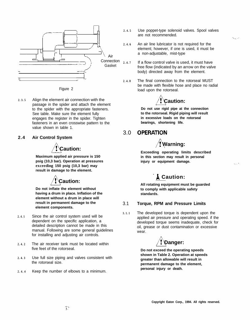
Apply a small amount of pliable gasket cementto the air connection gaskets to hold them inposition during installation. Install the airconnection gasket onto the air tube. SeeFigure 2.
Copyright Eaton Corp., 1994. All rights reserved.
AirConnection
Gasket
u
Figure 2
2.3.5 Align the element air connection with thepassage in the spider and attach the elementto the spider with the appropriate fasteners.See table. Make sure the element fullyengages the register in the spider. Tightenfasteners in an even crosswise pattern to thevalue shown in table 1.
2.4 Air Control System
n! Caution:Maximum applied air pressure is 150psig (10,3 bar). Operation at pressuresexceeding 150 psig (10,3 bar) mayresult in damage to the element.
0f Caution:l
Do not inflate the element withouthaving a drum in place. Inflation of theelement without a drum in place willresult in permanent damage to theelement components.
2.4.1 Since the air control system used will bedependent on the specific application, adetailed description cannot be made in thismanual. Following are some general guidelinesfor installing and adjusting air controls.
2.4.2 The air receiver tank must be located withinfive feet of the rotorseal.
2.4.3 Use full size piping and valves consistent withthe rotorseal size.
2.4.4 Keep the number of elbows to a minimum.
2.4.5
2.4.6
2.4.7
2.4.8
3.0.
3.1
3.1.1
Use poppet-type solenoid valves. Spool valvesare not recommended.
An air line lubricator is not required for theelement; however, if one is used, it must bea non-adjustable, mist-type
If a flow control valve is used, it must havefree flow (indicated by an arrow on the valvebody) directed away from the element.
The final connection to the rotorseal MUSTbe made with flexible hose and place no radialload upon the rotorseal.
Af Caution:0/ \Do not use rigid pipe at the connectionto the rotorseal. Rigid piping will resultin excessive loads on the rotorsealbearings, shortening life.
A! Warning:Exceeding operating limits describedin this section may result in personalinjury or equipment damage.
’ ! Caution:AAll rotating equipment must be guardedto comply with applicable safetystandards.
Torque, RPM and Pressure Limits
The developed torque is dependent upon theapplied air pressure and operating speed. if thedeveloped torque seems inadequate, check foroil, grease or dust contamination or excessivewear.
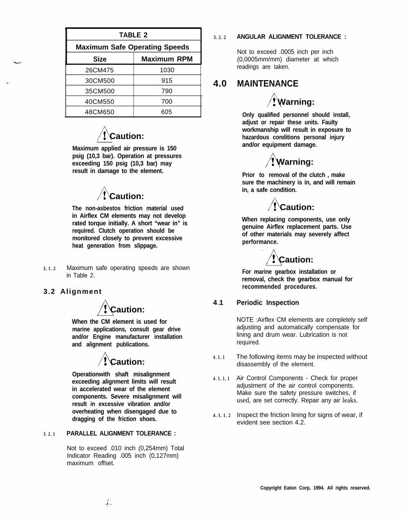
Af Danger:0Do not exceed the operating speedsshown in Table 2. Operation at speedsgreater than allowable will result inpermanent damage to the element,personal injury or death.
Copyright Eaton Corp., 1994. All rights reserved.
TABLE 2
Maximum Safe Operating Speeds
Size Maximum RPM
26CM475 1030
30CM500 915
35CM500 790
40CM550 700
48CM650 605
At Caution:0Maximum applied air pressure is 150psig (10,3 bar). Operation at pressuresexceeding 150 psig (10,3 bar) mayresult in damage to the element.
Af Caution:0The non-asbestos friction material usedin Airflex CM elements may not developrated torque initially. A short “wear in” isrequired. Clutch operation should bemonitored closely to prevent excessiveheat generation from slippage.
3.1.2 Maximum safe operating speeds are shownin Table 2.
3.2 Al ignment
Af Caution:0I \
When the CM element is used formarine applications, consult gear driveand/or Engine manufacturer installationand alignment publications.
At Caution:0Operationwith shaft misalignmentexceeding alignment limits will resultin accelerated wear of the elementcomponents. Severe misalignment willresult in excessive vibration and/oroverheating when disengaged due todragging of the friction shoes.
3.2.1 PARALLEL ALIGNMENT TOLERANCE :
Not to exceed .010 inch (0,254mm) TotalIndicator Reading .005 inch (0,127mm)maximum offset.
3.2.2
4.0
4 1.
4.1.1
4.1.1.1
4.1.1.2
ANGULAR ALIGNMENT TOLERANCE :
Not to exceed .0005 inch per inch(0,0005mm/mm) diameter at whichreadings are taken.
MAINTENANCE
A! Warning:Only qualified personnel should install,adjust or repair these units. Faultyworkmanship will result in exposure tohazardous conditions personal injuryand/or equipment damage.
A! Warning:Prior to removal of the clutch , makesure the machinery is in, and will remainin, a safe condition.
At Caution:0When replacing components, use onlygenuine Airflex replacement parts. Useof other materials may severely affectperformance.
Af Caution:0For marine gearbox installation orremoval, check the gearbox manual forrecommended procedures.
Periodic Inspection
NOTE :Airflex CM elements are completely selfadjusting and automatically compensate forlining and drum wear. Lubrication is notrequired.
The following items may be inspected withoutdisassembly of the element.
Air Control Components - Check for properadjustment of the air control components.Make sure the safety pressure switches, ifused, are set correctly. Repair any air leaks.
Inspect the friction lining for signs of wear, ifevident see section 4.2.
Copyright Eaton Corp, 1994. All rights reserved.
Af Caution:aOperation with friction material worn toless than minimum allowable thicknesswill result in damage to the drum.
4.1.1.3 Contamination of Shoes or Drum and elementwith oil or grease will reduce the developedtorque of the clutch or brake. Disassembly willbe required to clean any oil or grease build-up.
At Caution:0Do not attempt to use a solvent toremove oil or grease without firstremoving the element. While squirtinga solvent into an installed clutch mayimprove performance temporarily, a firehazard exists from heat generatedduring slippage.
At Caution:0/ J
Do not use compressed air to blow dustaccumulations out from between thefriction shoes. Although the frictionshoes do not contain asbestos, the dustcreated as the friction material wears,along with the dust from the operatingenvironment, may irritate the respiratorysystem.
4.1.2 Partial or complete disassembly is required toinspect the following items:
A! Caution:/ \Operation of the clutch on a drum thathas been worn, or has been machined,to less than minimum allowablediameter will result in damage to theelement components.
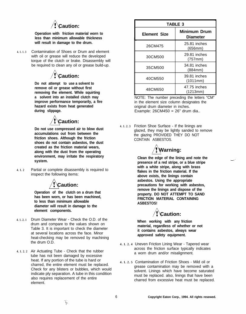
4.1.2.1 Drum Diameter Wear - Check the O.D. of thedrum and compare to the values shown onTable 3. It is important to check the diameterat several locations across the face. Minorheat-checking may be removed by machiningthe drum O.D.
4.1.2.2 Air Actuating Tube - Check that the rubbertube has not been damaged by excessiveheat. If any portion of the tube is hard orcharred, the entire element must be replaced.Check for any blisters or bubbles, which wouldindicate ply separation. A tube in this conditionalso requires replacement of the entireelement.
6 Copyright Eaton Corp., 1994. All rights resewed.
TABLE 3
Element SizeMinimum Drum
Diameter
26CM47525.81 inches
(656mm)
30CM50029.81 inches
(757mm)
35CM50034.81 inches
(884mm)
40CM55039.81 inches
(1011mm)
48CM65047.75 inches
(1213mm)
NOTE: The number preceding the letters “CM”in the element size column designates theoriginal drum diameter in inches.Example: 26CM450 = 26” drum dia..
4.1.2.3 Friction Shoe Surface - If the linings areglazed, they may be lightly sanded to removethe glazing PROVIDED THEY DO NOTCONTAIN ASBESTOS.
A! Warning:Clean the edge of the lining and note thepresence of a red stripe, or a blue stripewith a white stripe, along with brassflakes in the friction material. If theabove exists, the linings containasbestos. Using the appropriateprecautions for working with asbestos,remove the linings and dispose of theproperty. DO NOT ATTEMPT TO SANDFRICTION MATERIAL CONTAININGASBESTOS!
At Caution:0When working with any frictionmaterial, regardless of whether or notit contains asbestos, always wearapproved safety equipment.
4.1.2.4 Uneven Friction Lining Wear - Tapered wearacross the friction surface typically indicatesa worn drum and/or misalignment.
4.1.2.5 Contamination of Friction Shoes - Mild oil orgrease contamination may be removed with asolvent. Linings which have become saturatedmust be replaced. also, linings that have beencharred from excessive heat must be replaced.
Af Caution:0When using any solvent, always followthe appropriate safety precautions.
4.2 Friction Lining Replacement
NOTE: If any of the the linings have worn tothe minimum allowable thickness of .21inches (5mm), on the 26CM475, and .18inches (5mm) on all other CM element sizes,they must be replaced as a complete set. Fornew thicknesses see table 4.
TABLE 4
Friction Lining Thickness New
Model
26CM475
30CM50035CM50040CM55048CM650
Thickness-inches(mm)
.297(7.54)
.328(8.33)
At Caution:l/ \Use only genuine Airflex replacementparts. Use of other materials mayadversely effect performance.
4.2.1 Lay the element on a clean, level work surfacewith the air connection flange facing “up”.
4.2.2 Remove the shoe pin cotter pins and discard.Withdraw the shoe pins from the element.
4.2.3 Remove the friction shoe assemblies from theelement.
4.2.4 The friction blocks are riveted to the backingplate. Drill the rivets with a 15/64 inches(6mm) drill and tap the rivet body out.
4.2.5 Attach a replacementlining block to the back-ing plate with new drivepin rivets(000130x0071)(see Figure 3). Work fromthe center of the frictionlining out to the ends.The rivets are installedby driving the pin flushwith the head. Insure therivet flares after installed(see Figure 4).
4.2.6
4.2.7
5.0
5 1.
5.1.1
5 2.
5.2.1
6 0.
6 1.
6.1.1
Figure 4
Place the new friction shoe assemblies inposition. Insert the shoe pins with the headslocated on the air connection side of theelement.
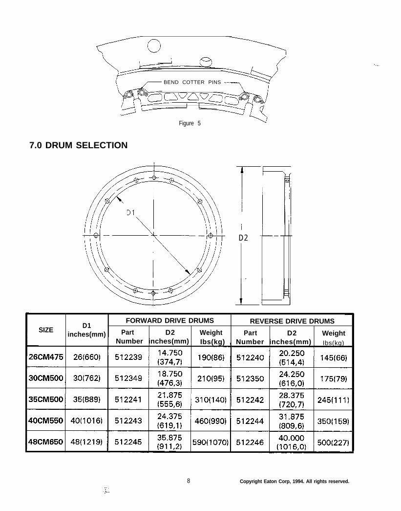
Slide the cotter pins through the holes of theshoe pins making sure that the open ends ofthe cotter pins face each other. Bend each endof the cotter pins so that equal lengths extendaround each side of the shoe pin; otherwisethe ends of the cotter pin may puncture thetube. (See Figure 5).
Element Assemblies
Element assemblies must always be storedflat. Storage in the standing position maycause the rims to go out-of-round.
Drums
Drums must be stored in a dry environment.Similar to element assemblies, storage of adrum in the standing position will adverselyaffect roundness.
ORDERING INFORMATION/TECHNICAL ASSISTANCE
Equipment Reference
In any correspondence regarding Airflexequipment, refer to the information on theproduct nameplate. If not available, note thedrum diameter, mounting arrangement or anyother special features and call or write:
Eaton CorporationAirflex Division9919 Clinton RoadCleveland, Ohio 44144Ph: 216-281-2211FAX: 216-281-3890
Figure 3
7 Copyright Eaton Corp, 1994. All rights reserved.
BEND COTTER PINS
Figure 5
7.0 DRUM SELECTION
D2
D1FORWARD DRIVE DRUMS REVERSE DRIVE DRUMS
SIZEinches(mm) Part D2 Weight Part D2 Weight
Number inches(mm) Ibs(kg) I Number inches(mm) Ibs(kg)
8 Copyright Eaton Corp, 1994. All rights reserved.
8 0.
ITEM
CompleteElement
(1)Rim& TubeAssembly
(2)Friction Blocks
(2A)Rivits
(3)90 degree ElbowAssembly
(4).Air
ConnectionTube
(5).Air
ConnectionGasket
(6)Shoe Pin
(7)Friction Shoe
Assembly
(8)Cotter Pin
26CM475 3OCM500
5 1 2 0 4 7 512050P/L 146211 P/L 146212
512046 5120491 each 1 each
3 0 7 4 9 8 3 0 7 4 8 924 each 28 each
0 0 0 1 3 0 x 0 0 7 1 0 0 0 1 3 0 x 0 0 7 1144 each 168 each
0 0 0 0 9 2 x 0 0 0 6 0 0 0 0 9 2 x 0 0 0 71 each 1 each
2 0 2 1 6 9 2 0 2 1 7 31 each 1 each
0 0 0 0 7 2 x 0 0 5 4 0 0 0 0 7 2 x 0 0 5 43 each 3 each
2 0 2 1 7 9 2 0 1 9 3 624 each 28 each
4 1 4 7 9 1 3 0 7 4 9 912 each 14 each
0 0 0 0 6 5 x 0 0 0 7 0 0 0 0 6 5 x 0 0 0 724 each 28 each
ELEMENT SIZE
35CM500
5 1 1 9 8 3P/L 146207
5 1 1 9 2 21 each
3 0 7 4 8 932 each
0 0 0 1 3 0 x 0 0 7 1 192 each*
0 0 0 0 9 2 x 0 0 0 81 each
2 0 1 9 4 21 each
0 0 0 0 7 2 x 0 0 5 43 each
2 0 1 9 3 632 each
4 1 4 7 8 216 each
0 0 0 0 6 5 x 0 0 0 732 each
40CM550
5 1 1 9 9 0P/L 146208
5 1 1 9 8 91 each
3 0 7 4 9 036 each
000130x0071 216 each
0 0 0 0 9 2 x 0 0 0 81 each
2 0 2 6 9 91 each
0 0 0 0 7 2 x 0 0 5 63 each
2 0 2 1 5 036 each
4 1 4 7 8 318 each
0 0 0 0 6 5 x 0 0 0 736 each
48CM650
5 1 2 0 0 0P/L 146209
5 1 1 9 9 91 each
307491 42 each
0 0 0 1 3 0 x 0 0 7 1 294 each
0 0 0 0 9 2 x 0 0 0 81 each
2 0 2 6 9 91 each
0 0 0 0 7 2 x 0 0 5 63 each
2 0 2 7 0 042 each
4 1 4 7 8 421 each
0 0 0 0 6 5 x 0 0 0 742 each
9 Copyright Eaton Corp, 1994. All rights reserved.
PDF format
Form ML-318Revised September 3, 1997
Eaton CorporationAirflex Division9919 Clinton RoadCleveland, Ohio 44144
Printed in U.S.A.
EATON PRODUCT WARRANTYSubject to the conditions statedherein, Eaton Corporation warrants tothe Purchaser that each new AirflexProduct manufactured by Eaton will befree from failures caused by defects inmaterial and workmanship, and willdeliver its rated capacity, for a periodof twelve (12) months from the date ofshipment to Purchaser, provided suchProduct is properly installed, properlymaintained, operated under normalconditions and with competentsupervision. Warranty claims shall bemade in writing and the part or partsshall, if requested by Airflex Division,be returned prepaid to the AirflexDivision for inspection. Upon adetermination that a defect exists,Eaton shall thereupon correct anydefect, at its option either by repairingany defective part or parts or bymaking available at Eaton’s plant arepaired or replacement part. Thiswarranty does not extend to normalwear parts or components of theProduct, such as friction material andfriction surfaces.
LIMITATION OF WARRANTYTHE FOREGOING WARRANTY ISEXCLUSIVE AND IN LIEU OF ALLOTHER WARRANTIES WHETHERWRITTEN, ORAL OR IMPLIED. ANYIMPLIED WARRANTY OFMERCHANTABILITY OR FITNESSFOR A PARTICULAR PURPOSE ARESPECIFICALLY EXCLUDED.
In no event shall Eaton be liable forspecial, incidental or consequentialdamages. Eaton’s liability arising outof the supplying of such Product, or itsuse, whether in warranty, contract orotherwise, shall in no case exceed thecost of correcting defects in theProducts as herein provided. Uponexpiration of the twelve (12) monthperiod, all such liability shallterminate. THE FOREGOING SHALLCONSTITUTE THE SOLE REMEDYOF PURCHASER AND THE SOLELIABILITY OF EATON.