INSTALLATION, OPERATION AND SERVICE MANUAL SALAMANDER S86 WARNINGS IMPROPER INSTALLATION, ADJUSTMENT, ALTERATION, SERVICE OR MAINTENANCE CAN CAUSE INJURY OR DEATH. THE INSTRUCTION MANUAL MUST BE READ CAREFULLY BEFORE INSTALLING, OPERATING OR SERVICING THIS EQUIPMENT TO BE INSTALLED ONLY BY AN AUTHORISED PERSON IN ACCORDANCE WITH AS 5601, LOCAL AUTHORITY, GAS, ELECTRICITY, ANY APPLICABLE STATUTORY REGULATIONS AND MANUFACTURER REQUIREMENTS. Salamander Manual Page 1 Revision: 13 Sep 07 OPERATOR MANUAL S86 130907.doc
Transcript
INSTALLATION, OPERATION
AND SERVICE MANUAL SALAMANDER
S86
WARNINGS
IMPROPER INSTALLATION, ADJUSTMENT, ALTERATION, SERVICE OR MAINTENANCE CAN CAUSE INJURY OR DEATH. THE INSTRUCTION MANUAL MUST BE READ CAREFULLY BEFORE INSTALLING, OPERATING OR SERVICING THIS EQUIPMENT
TO BE INSTALLED ONLY BY AN AUTHORISED PERSON IN ACCORDANCE WITH AS 5601, LOCAL AUTHORITY, GAS, ELECTRICITY, ANY APPLICABLE STATUTORY REGULATIONS AND MANUFACTURER REQUIREMENTS.
THIS EQUIPMENT IS DESIGNED FOR COMMERCIAL CATERING PURPOSES AND WILL GENERATE SIGNIFICANT HEAT. HOT SURFACES WILL CAUSE BURNS. A HAZARD AND RISK ASSESSMENT MUST BE UNDERTAKEN BY OWNERS AND ALL OPERATORS MADE AWARE OF THESE.
DO NOT STORE OR USE FLAMMABLE LIQUIDS NEAR THIS APPLIANCE.
DO NOT SPRAY AEROSOLS NEAR THIS APPLIANCE WHILE IT IS IN OPERATION.
INSTALLATION CLEARANCES AS SPECIFIED MUST BE OBSERVED.
IF YOU SMELL GAS, TURN THE UNIT OFF AND THE MAIN GAS SUPPLY VALVE TO THE UNIT. CONTACT YOUR GAS SUPPLIER OR AN AUTHORISED PERSON.
BEFORE TURNING ON THE MAIN GAS SUPPLY, CHECK THE UNIT TO BE CERTAIN THAT ALL THE VALVES ARE IN THE “OFF” POSITION.
CONGRATULATIONS Comcater thanks you for choosing this product and welcomes you to the ever-growing Comcater customer circle. This product has been specifically designed by Comcater to meet a wide rage of applications and represents the best quality and highest value equipment. Please read the instruction manual carefully to ensure the safe and reliable operation and performance of your equipment. Should you ever require service, you will be supported by Comcater’s trained and qualified service network – the largest available. Comcater assures you of every support and wishes you every business success. Michael Wood Managing Director Comcater
GENERAL INFORMATION .............................................................................6 INSPECTION............................................................................................6 OPERATOR MANUAL ..............................................................................6 INSTALLATION.........................................................................................6 GAS CONNECTION .................................................................................6 GAS PRESSURE .....................................................................................6 COMMISSIONING....................................................................................6
SPECIFICATIONS ...........................................................................................7 INSTALLATION.........................................................................................7 GAS SUPPLY PRESSURE.......................................................................9 NOMINAL GAS CONSUMPTION .............................................................9 TEST POINT PRESSURE ........................................................................9 VENTILATION AND AIR SUPPLY.............................................................9 GENERAL SPECIFICATIONS ................................................................10
SERVICE .......................................................................................................17 RECOMMENDED SERVICE ..................................................................17 SERVICE INFORMATION ......................................................................17 BURNER ADJUSTMENTS .....................................................................18 CONVERSION INSTRUCTIONS............................................................19 SPARE PARTS .......................................................................................20
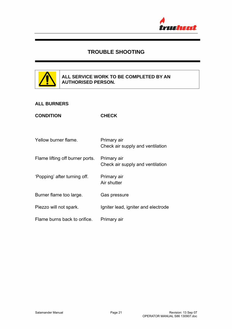
TROUBLE SHOOTING .................................................................................21 ALL BURNERS.......................................................................................21
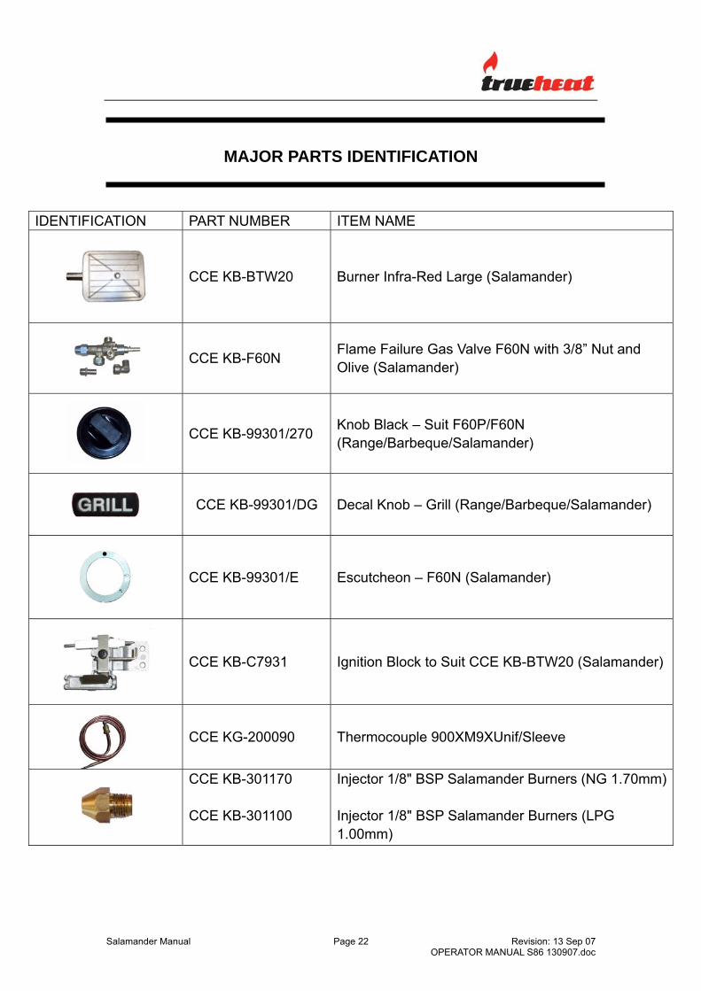
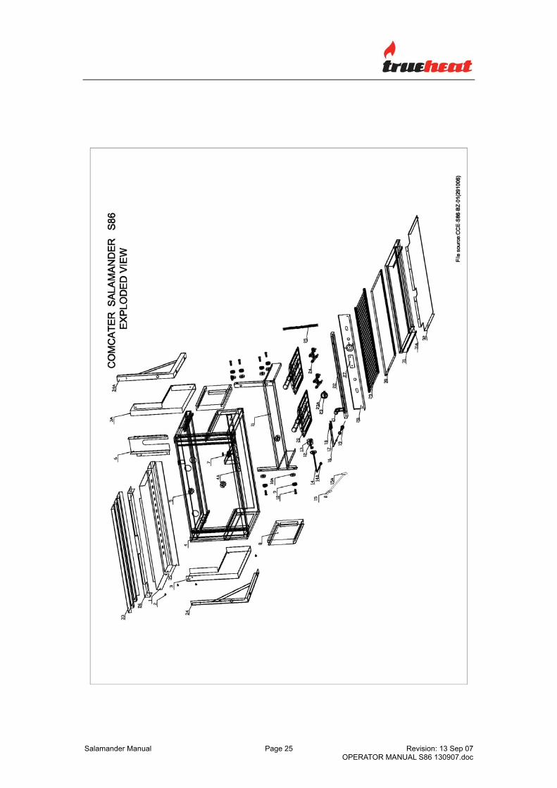
SALAMANDER – MAJOR PARTS IDENTIFICATION ..................................22 SALAMANDER – EXPLODED VIEWS AND BILL OF MATERIALS ...................................................................................25 DRAWINGS ...................................................................................................27
INTRODUCTION GENERAL This equipment is designed for commercial catering purposes and incorporates a wide range of design features to benefit the customer. This versatility will satisfy a wide range of customer needs. WARRANTY This product is warranted for 12 months parts and labour and is subject to the correct installation, operation, maintenance and care of the equipment. Warranty does not extend to: • Damages caused in shipment.
• Damage as a result of incorrect installation.
• Damage as a result of incorrect operation.
• Damages caused by unauthorised service and use of non-original parts.
• Gas supply issues to the equipment.
• Failure resulting from improper maintenance.
• Failure as a result of tampering with, removal of, or changing any preset
control or safety device.
• Service ‘After hours’.
• Conditions as defined in Comcater terms and condition of sale. For all warranty work, authorized service and genuine and authorized spare parts, please contact Comcater Service 03 8369 4600. Please ensure you quote the Model and Serial Number of the unit. The Model and Serial Number of the unit is recorded on the sales invoice. Alternatively, the information is recorded on the front of the unit and on the data plate located behind the front panel.
GENERAL INFORMATION INSPECTION Please inspect the unit on receipt. If the unit is damaged, contact the carrier immediately and file a damage claim with them. Save all packing materials when filing a claim. Freight damage claims are the responsibility of the purchaser and are not covered under warranty. OPERATOR MANUAL This manual contains important information for your safety and the installation, operation, maintenance and service of this equipment. Please read the manual carefully and ensure all operators of the equipment are aware of the contents and safety requirements. Warning: You must assess all hazards and risks associated with the operation of the equipment in your environment and advise all operators of these. INSTALLATION This equipment must be installed by an authorized person in accordance with AS 5601, local authority, gas, electricity, any applicable statutory regulations and manufacturer requirements. GAS CONNECTION The appliance must be connected by an authorized person to the gas type specified on the unit. The gas type is shown adjacent to the rear gas connection point on the back panel and on the data plate. Connect to and use only the correct type of gas. GAS PRESSURE The authorized person installing this equipment must ensure that the gas operating pressure is the same as shown on the rating plate, the test point pressure is correct (refer page 9) and that there is sufficient gas volume. COMMISSIONING The authorized person installing this equipment must commission the equipment in accordance with AS 5601 - gas leakage, operational checking, adjustments and instructing the owner on use of the equipment are prescribed requirements.
THIS EQUIPMENT MUST BE INSTALLED BY AN AUTHORIZED PERSON IN ACCORDANCE WITH AS 5601, LOCAL AUTHORITY, GAS, ELECTRICITY, ANY APPLICABLE STATUTORY REGULATIONS AND MANUFACTURER REQUIREMENTS.
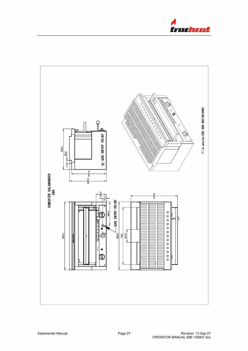
NOTE: INSTALLATION IS THE RESPONSIBILITY OF THE OWNER Gas Inlet Connection: ½” BSP Female. Gas Connection Point: The gas connection point is located at the rear of
the unit (300 mm from the right hand side and 45mm above the base of the unit) Details are shown in the drawing at the rear of this manual.
Gas Connection: The appliance must be connected by an
authorized person to the gas type specified on the unit. The gas type is shown adjacent to the gas connection point and on the data plate. Connect to and use only the correct type of gas.
The authorized person installing this equipment must comply with AS 5601 requirements. Prescribed requirements include, commission the equipment, gas leakage testing, operational checking and adjustments.
All units are tested and adjusted at the factory; however, burners and pilots must be checked at the installed location and adjusted if necessary.
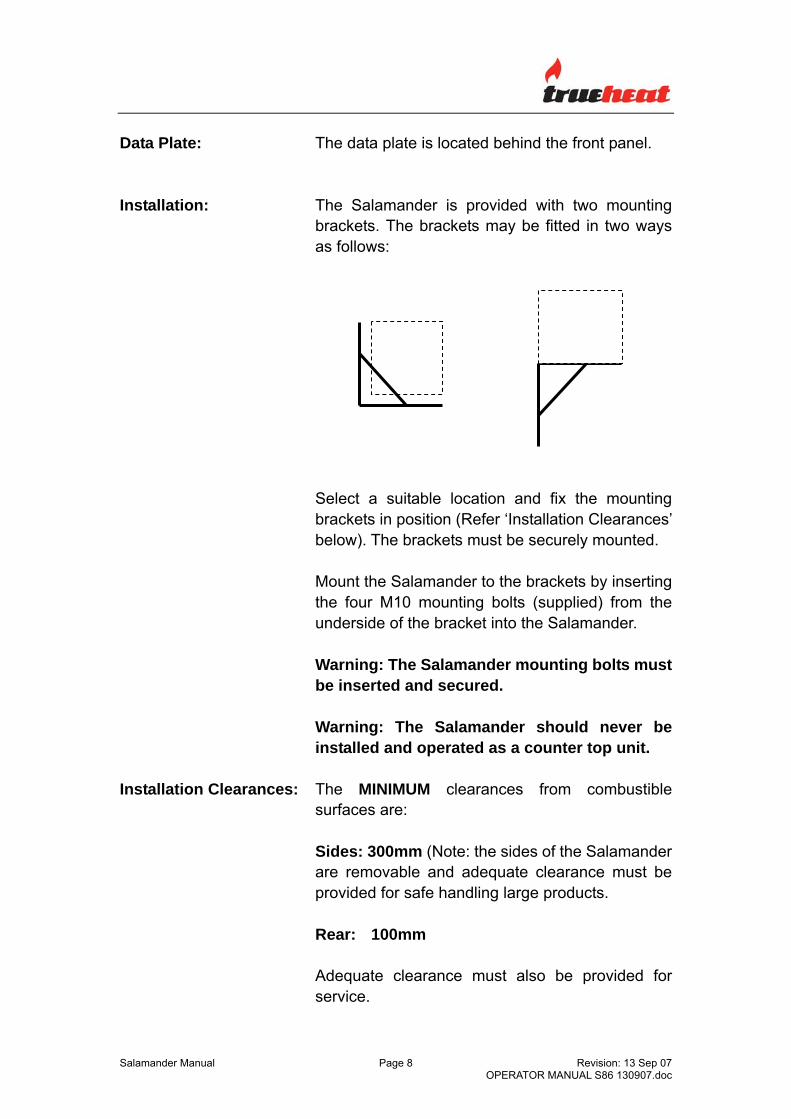
Data Plate: The data plate is located behind the front panel. Installation: The Salamander is provided with two mounting
brackets. The brackets may be fitted in two ways as follows:
Select a suitable location and fix the mounting brackets in position (Refer ‘Installation Clearances’ below). The brackets must be securely mounted.
Mount the Salamander to the brackets by inserting the four M10 mounting bolts (supplied) from the underside of the bracket into the Salamander.
Warning: The Salamander mounting bolts must be inserted and secured. Warning: The Salamander should never be installed and operated as a counter top unit.
Installation Clearances: The MINIMUM clearances from combustible surfaces are:
Sides: 300mm (Note: the sides of the Salamander are removable and adequate clearance must be provided for safe handling large products. Rear: 100mm Adequate clearance must also be provided for service.
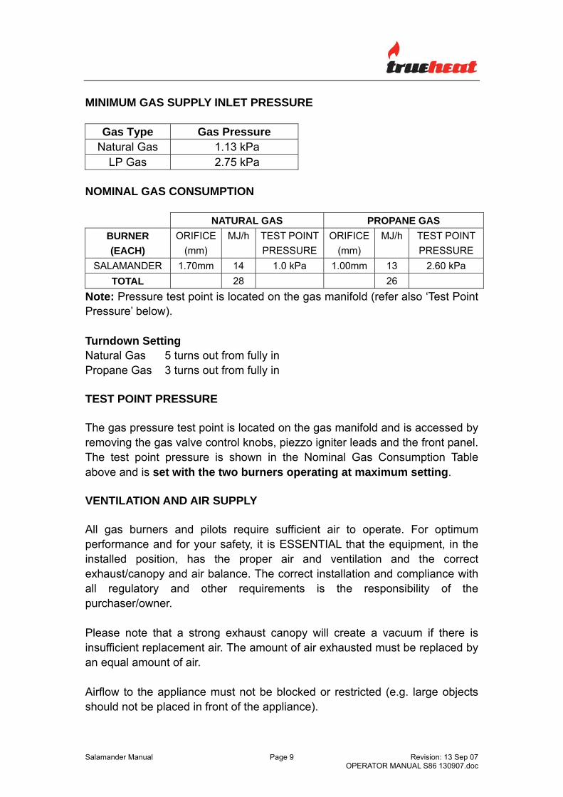
Note: Pressure test point is located on the gas manifold (refer also ‘Test Point Pressure’ below). Turndown Setting Natural Gas 5 turns out from fully in Propane Gas 3 turns out from fully in TEST POINT PRESSURE The gas pressure test point is located on the gas manifold and is accessed by removing the gas valve control knobs, piezzo igniter leads and the front panel. The test point pressure is shown in the Nominal Gas Consumption Table above and is set with the two burners operating at maximum setting. VENTILATION AND AIR SUPPLY All gas burners and pilots require sufficient air to operate. For optimum performance and for your safety, it is ESSENTIAL that the equipment, in the installed position, has the proper air and ventilation and the correct exhaust/canopy and air balance. The correct installation and compliance with all regulatory and other requirements is the responsibility of the purchaser/owner. Please note that a strong exhaust canopy will create a vacuum if there is insufficient replacement air. The amount of air exhausted must be replaced by an equal amount of air. Airflow to the appliance must not be blocked or restricted (e.g. large objects should not be placed in front of the appliance).
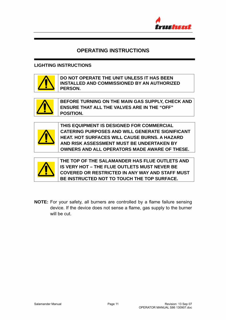
DO NOT OPERATE THE UNIT UNLESS IT HAS BEEN INSTALLED AND COMMISSIONED BY AN AUTHORIZED PERSON.
BEFORE TURNING ON THE MAIN GAS SUPPLY, CHECK AND ENSURE THAT ALL THE VALVES ARE IN THE “OFF” POSITION.
THIS EQUIPMENT IS DESIGNED FOR COMMERCIAL CATERING PURPOSES AND WILL GENERATE SIGNIFICANT HEAT. HOT SURFACES WILL CAUSE BURNS. A HAZARD AND RISK ASSESSMENT MUST BE UNDERTAKEN BY OWNERS AND ALL OPERATORS MADE AWARE OF THESE.
THE TOP OF THE SALAMANDER HAS FLUE OUTLETS AND IS VERY HOT – THE FLUE OUTLETS MUST NEVER BE COVERED OR RESTRICTED IN ANY WAY AND STAFF MUST BE INSTRUCTED NOT TO TOUCH THE TOP SURFACE.
NOTE: For your safety, all burners are controlled by a flame failure sensing
device. If the device does not sense a flame, gas supply to the burner will be cut.
WARNING: Ensure there are no restric NOTE: Ensure the g SALAMANDER BUR Starting from the OFF Fully depress the coburner – repeat untilseconds after the bBURNER is alight, treleased. The equip(highest heat) and LE NOTE: When the eqlikely to be easier ttorch rather than thWARNING: NEVER Shut Down Turn the control knob NOTE: If the burnersafety device would then be necessary to
Salamander Manual
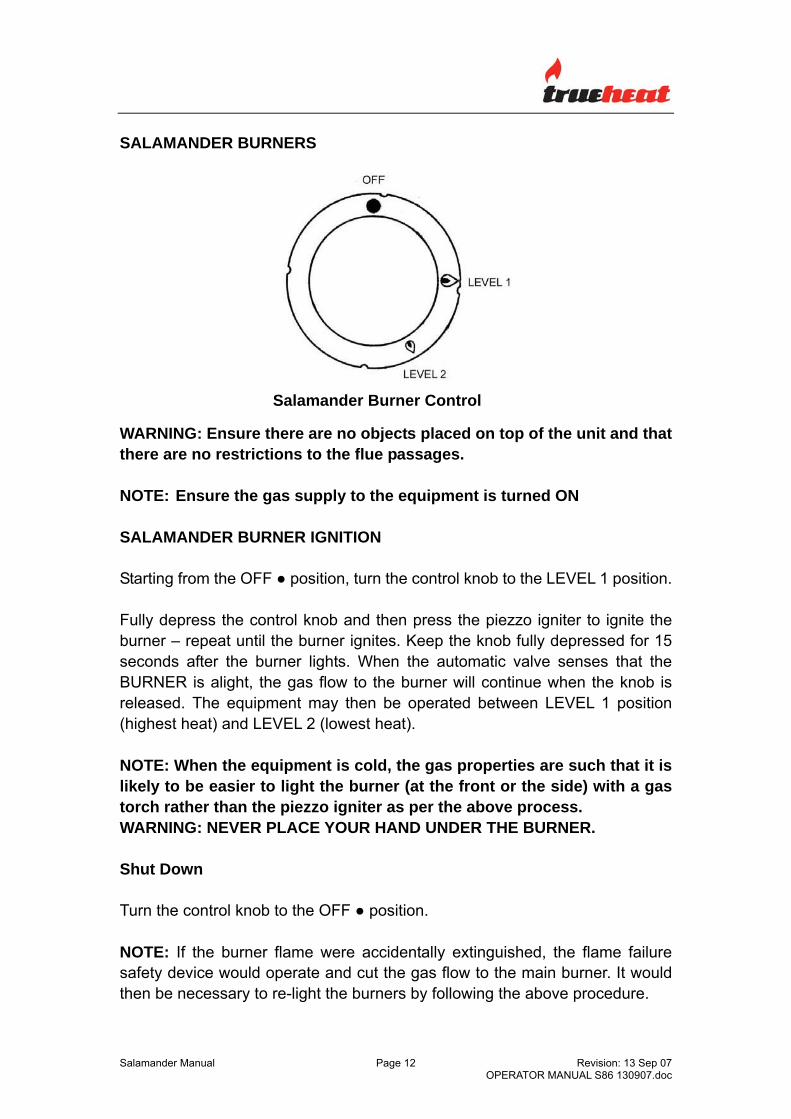
Salamander Burner Control
there are no objects placed on top of the unit and that tions to the flue passages.
as supply to the equipment is turned ON
NER IGNITION
● position, turn the control knob to the LEVEL 1 position.
ntrol knob and then press the piezzo igniter to ignite the the burner ignites. Keep the knob fully depressed for 15 urner lights. When the automatic valve senses that the he gas flow to the burner will continue when the knob is ment may then be operated between LEVEL 1 position VEL 2 (lowest heat).
uipment is cold, the gas properties are such that it is o light the burner (at the front or the side) with a gas e piezzo igniter as per the above process. PLACE YOUR HAND UNDER THE BURNER.
to the OFF ● position.
flame were accidentally extinguished, the flame failure operate and cut the gas flow to the main burner. It would re-light the burners by following the above procedure.
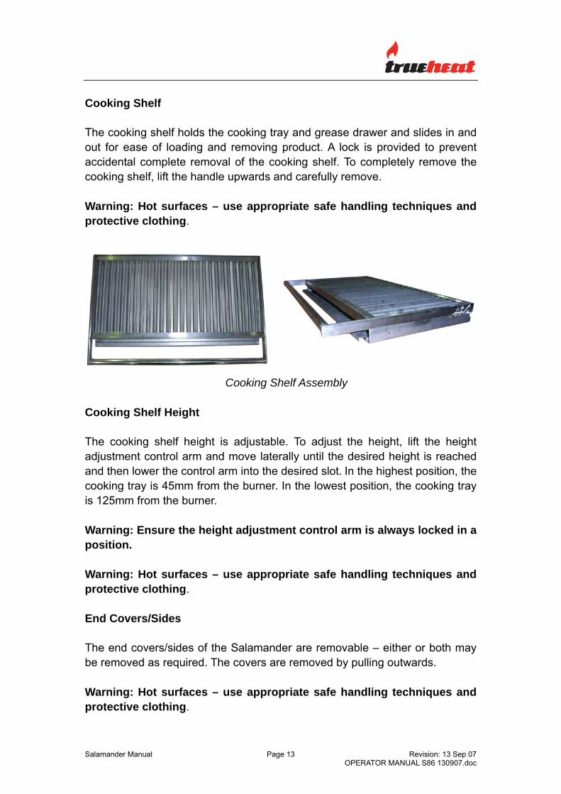
Cooking Shelf The cooking shelf holds the cooking tray and grease drawer and slides in and out for ease of loading and removing product. A lock is provided to prevent accidental complete removal of the cooking shelf. To completely remove the cooking shelf, lift the handle upwards and carefully remove. Warning: Hot surfaces – use appropriate safe handling techniques and protective clothing.
Cooking Shelf Assembly
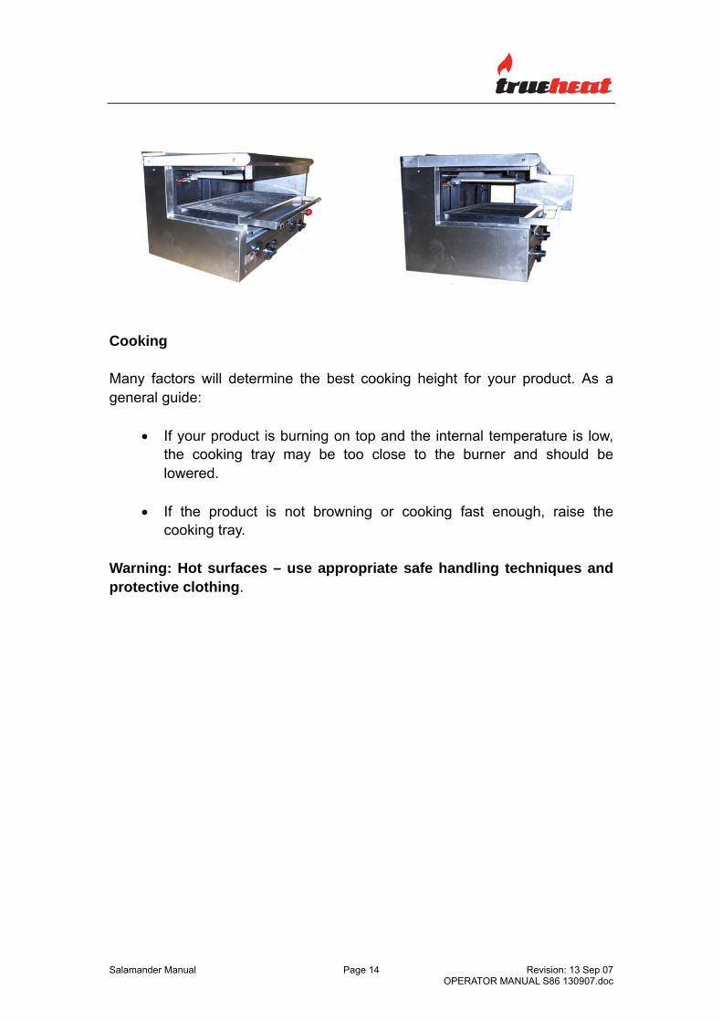
Cooking Shelf Height
The cooking shelf height is adjustable. To adjust the height, lift the height adjustment control arm and move laterally until the desired height is reached and then lower the control arm into the desired slot. In the highest position, the cooking tray is 45mm from the burner. In the lowest position, the cooking tray is 125mm from the burner.
Warning: Ensure the height adjustment control arm is always locked in a position.
Warning: Hot surfaces – use appropriate safe handling techniques and protective clothing. End Covers/Sides The end covers/sides of the Salamander are removable – either or both may be removed as required. The covers are removed by pulling outwards. Warning: Hot surfaces – use appropriate safe handling techniques and protective clothing.
USE ONLY SUITABLE CHEMICALS AND OBSERVE ALL MANUFACTURER SAFETY REQUIREMENTS FOR SAFE HANDLING AND USE.
Note: The equipment must be kept clean to ensure safe and reliable operation and performance. Warning: Empty the grease drawer as necessary and clean. Excessive deposits in the grease drawer may cause flare-ups. Warning: Hot surfaces – use appropriate safe handling techniques and protective clothing. The following procedures are recommended – the amount of cleaning will depend on the equipment usage and the products being cooked. After each use: Ensure the cooking tray and grease draw are clean. Excessive deposits in the grease drawer may cause flare-ups (Refer ‘Cleaning Stainless Steel’ below). Daily: The cooking shelf and grease tray should be removed and cleaned with hot water and detergent. Wipe and clean all exterior surfaces (Refer ‘Cleaning Stainless Steel’ below). Weekly: Inspect all surfaces of the cooking chamber, including burners, and clean as necessary. More frequent cleaning may be necessary based on equipment usage. Burners: The burners may be removed and cleaned as necessary by undoing the burner retaining screw, removing the piezzo ignition lead, releasing the thermocouple from the ignition block (held by spring force), lifting up the burner and pulling forward – after cleaning, ensure the burner is dry and replaced in reverse order in the correct position. Warning: If your burners require cleaning and you are not confident in performing this task, please call for service.
Lifting Mechanism: It may be necessary to lubricate the lifting mechanism on occasions. If required, use industry approved, heat resistant, food safe grease on the chain and sprockets. These are accessed by removing the protective cover. CLEANING STAINLESS STEEL Regularly wipe surfaces with hot water and detergent (use non-abrasive cleaning aids as necessary). Rinse the washed area with a wet sponge and clean water and wipe the area dry to prevent streaking. Follow this process and wash a small area at a time to prevent chemical residue and streaking. Stainless steel may discolour if overheated. These stains can usually be removed using an appropriate powder/paste. To scrape off heavy deposits of grease and oil, use only wood or plastic tools as necessary. Note: Never use steel wool to clean stainless steel. Note: Damage may occur if chemicals not suitable for stainless steel are used. Note: Use non-abrasive cleaning aids (Brushes/Pads).
FOR YOUR SAFETY, ALL SERVICE WORK MUST BE CARRIED OUT BY AN AUTHORISED PERSON AND USE ONLY ORIGINAL SUPPLIED AND SPECIFIED PARTS.
TEST ALL FITTINGS, PIPES AND PIPE CONNECTIONS FOR LEAKS IN ACCORDANCE WITH APPROVED GAS LEAK TEST PROCESSES AND METHODS. DO NOT USE A FLAME.
Note: When checking gas test point pressure, ensure that all other equipment on the same line is turned ‘ON’ and operating. RECOMMENDED SERVICE It is recommended that an authorized person service your appliance every 12 months. This period is for guidance purpose only and may vary based on usage of the equipment and operator care. Prescribed service tasks include;
• Functional test of all components and clean, lubricate and adjust as necessary.
• Inspect and clean all gas valves and lubricate with an industry approved lubricant.
• Inspect all gas piping. • Check and adjust specified gas pressures. • Leak test. • Full operational, performance and safety test.
SERVICE INFORMATION
• To access gas valves, remove control knobs and the front panel. • To remove a gas valve, disconnect the gas valve at the manifold tee
spigot connection and remove the valve. • To access thermocouples, release the thermocouple from the ignition
block (spring clip) or remove the top of the unit. • To access burners, remove the top panel, undo the retaining screw,
remove the piezzo ignition lead, release the thermocouple from the ignition block (held by spring force), lift up the burner and pull forward – re-assemble in reverse order.
• Ensure that all valves are in the OFF position. • Turn on the main gas supply valve. • Light the burners. • Leak test all valves and fittings using approved methods. • Correct any leaks as required and re-check. • Shut off all valves and set controls to the “OFF” position.
Test Point Pressure The test point is located on the gas manifold. The gas manifold and pressure test point is accessed by removing the gas valve control knobs and the front panel. The test point pressure is shown in the Nominal Gas Consumption Table and is set with the two burners operating at maximum setting. Burner Adjustment The burner orifices are fixed as specified and cannot be adjusted. The specified gas rate will be achieved if the gas supply pressure and test point pressure is correct and all gas components are clean and free of blockages. The turndown (low flame) setting can be adjusted by adjusting the screw on the gas valve. A distinct blue flame over the entire port area of the burner will be achieved at full rate when the air supply is correct. If the flame is yellow and wavy, the cause needs to be established. WARNING: If you are not competent in performing any service task or require assistance, please contact Comcater Service 03 8369 4600.
ENSURE GAS IS ISOLATED WHILST PERFORMING CONVERSION WORK. PERFORM A LEAK TEST BEFORE IGNITING AND MAKING BURNER AND PILOT ADJUSTMENTS.
TO PROPANE GAS
Regulator Change regulator to PROPANE gas configuration and adjust as necessary.
Burner Injectors Access and change the injectors to PROPANE Gas
injectors (refer Nominal Gas Consumption Table).
LEAK TEST IN ACCORDANCE WITH APPROVED METHODS Ignite burners and adjust. AMEND DATA PLATE AND APPLY ‘PROPANE’ GAS LABEL TO NATURAL GAS (NG) Regulator Change regulator to NG gas configuration and
adjust as necessary. Burner Injectors Access and change the injectors to NG Injectors
(refer Nominal Gas Consumption Table). LEAK TEST IN ACCORDANCE WITH APPROVED METHODS Ignite burners and adjust. AMEND DATA PLATE AND APPLY ‘NATURAL GAS’ LABEL.
SPARE PARTS A list of major spare part items is shown at the end of this manual. These parts and all other parts used in the Comcater Salamander are available from Comcater. Warning: Use only genuine spare parts. Warning: Use of non-authorised parts voids warranty and equipment approval.
N o t e s _______________________________________________________________________ _______________________________________________________________________ _______________________________________________________________________ _______________________________________________________________________ _______________________________________________________________________ _______________________________________________________________________ _______________________________________________________________________ _______________________________________________________________________ _______________________________________________________________________ _______________________________________________________________________ _______________________________________________________________________ _______________________________________________________________________ _______________________________________________________________________ _______________________________________________________________________ _______________________________________________________________________ _______________________________________________________________________ _______________________________________________________________________