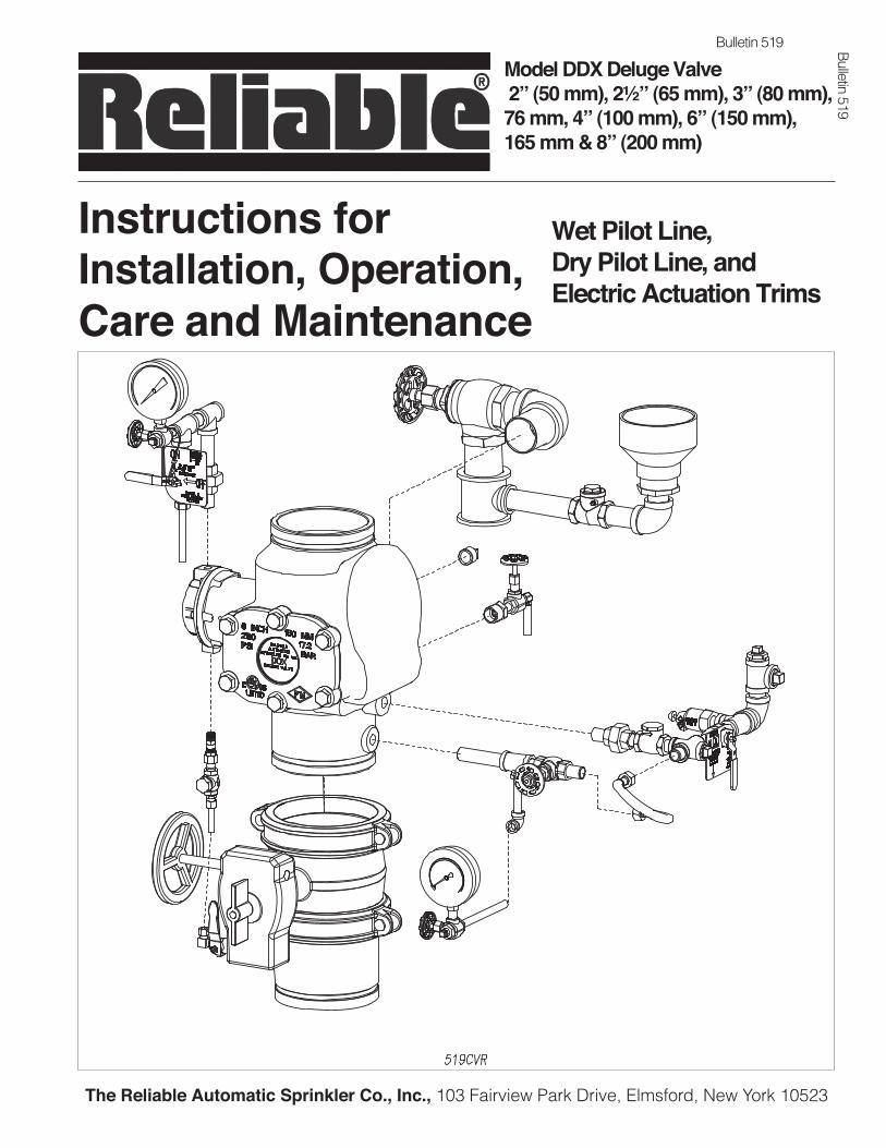
The Reliable Automatic Sprinkler Co., Inc., 103 Fairview Park Drive, Elmsford, New York 10523 Model DDX Deluge Valve 2” (50 mm), 2½” (65 mm), 3” (80 mm), 76 mm, 4” (100 mm), 6” (150 mm), 165 mm & 8” (200 mm) Bulletin 519 Bulletin 519 Instructions for Installation, Operation, Care and Maintenance Wet Pilot Line, Dry Pilot Line, and Electric Actuation Trims
Transcript
The Reliable Automatic Sprinkler Co., Inc., 103 Fairview Park Drive, Elmsford, New York 10523
Model DDX Deluge Valve 2” (50 mm), 2½” (65 mm), 3” (80 mm), 76 mm, 4” (100 mm), 6” (150 mm),165 mm & 8” (200 mm)
Bulletin 519
Bulletin 519
Instructions forInstallation, Operation, Care and Maintenance
Wet Pilot Line, Dry Pilot Line, andElectric Actuation Trims
GeneralThe Reliable Model DDX Deluge Valve is a hydraulically op-
erated, differential latching clapper-type valve designed for use as primary control valve in deluge, preaction, or special types of fire protection systems. Following operation, the valve is easily reset externally (see Fig.1).
The Wet Pilot Line Trim set is connected to the push rod chamber outlet and provides a one and one quarter inch main drain on 2” (50mm), 2½” (65mm), 76mm and 3” (80mm) valve sizes or a two inch main drain on 4” (100mm), 165mm, 6” (150mm) and 8” (200mm) valve sizes, alarm test, supply pres-sure gauge, and the push rod chamber supply connections. Releasing devices that can be used are wet pilot line detectors (Model F1-FTR) or hydraulic manual emergency stations/pull boxes (Models A & B).
Two alternate actuation trim sets, Dry Pilot Line or Electric Ac-tuation, are available when dry pilot sprinklers or solenoid valves are used for releasing. Actuation by solenoid valves enables a full range of electrical detectors to be used for remote sensing.
Listings & Approvals:(Only when used with Reliable’s Trim Sets.)1. Listed by Underwriters Laboratories, Inc. and UL certified
for Canada (cULus).2. Certified by Factory Mutual Approvals (FM).3. NYC MEA 258-93-E4. LPCB (4” (100mm), 165mm, 6” (150mm) & 8”
(200mm) only)5. CE6. VdS Schadenverhütung GmbH
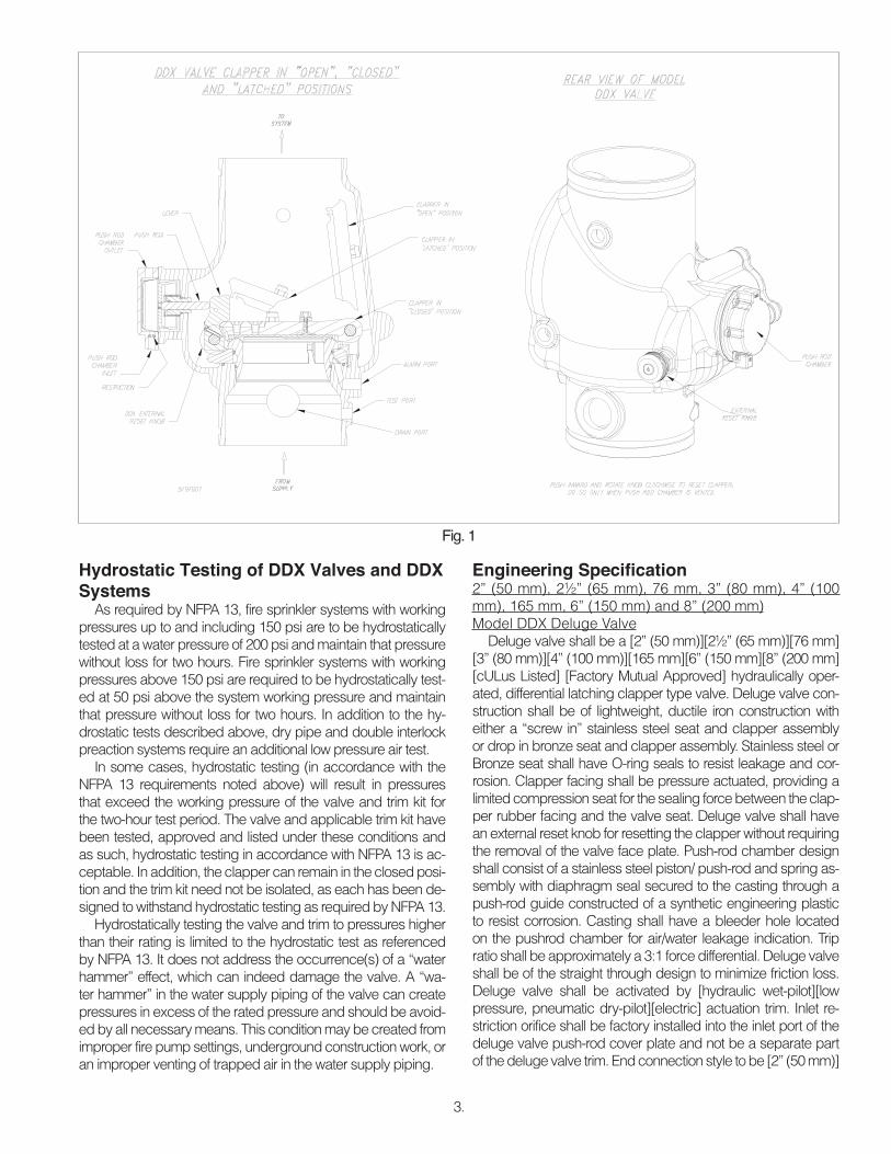
Valve OperationThe Reliable Model DDX Deluge Valve is shown in both
closed and open positions in Fig. 1. In the closed position, the supply pressure acts on the underside of the clapper and also on the push rod through the push rod chamber’s inlet restric-tion. The resultant force due to the supply pressure acting on the push rod is multiplied by the mechanical advantage of the lever and is more than sufficient to hold the clapper closed against normal supply pressure surges.
When a fire is detected, a releasing device vents the push rod chamber to atmosphere through the chamber’s outlet. Since the pressure cannot be replenished through the inlet restriction as rapidly as it is vented, the push rod chamber pressure falls instantaneously. When the push rod chamber pressure ap-proaches approximately one-third of the supply pressure, the upward force of the supply pressure acting beneath the clapper overcomes the lever-applied force thereby opening the clapper.
Once the clapper has opened, the lever acts as a latch, pre-venting the clapper from returning to the closed position. Water from the supply flows through the Deluge Valve into the system piping. Water also flows through the Deluge Valve alarm outlet to the alarm devices.
After system shutdown, resetting the Model DDX Deluge Valve is quite simple. Doing so only requires pushing in and turning the reset knob at the rear of the valve (see Fig.1). The external reset feature of the Model DDX Deluge Valve provides a means for simple, economical system testing, which is one es-sential facet of a good maintenance program. The external reset
feature does not, however, eliminate another important facet of good maintenance, namely, periodic cleaning and inspection of the internal valve parts.
In the event that water builds up inside the valve due to con-densate from the air supply system or water left inside from valve system testing, a drain is available for venting. After clos-ing the main supply valve, a small valve over the drain cup can be opened slightly until the water inside the valve body and the main pipe column has drained.
Whenever ambient temperature conditions are high, the water temperature in the Model DDX Deluge Valve’s pushrod chamber could possibly increase, thereby increasing the pres-sure in the chamber to values exceeding the rated pressure of the system. In an indoor installation where standard room tem-peratures are exceeded, a pressure relief kit may be needed. Pressure relief kit, P/N 6503050001, can be installed into the pushrod chamber’s release line to limit the pressure to 250 psi (17,2 bar).
Reliable Model DDX Deluge Valve with associated trim sizes 2” (50 mm), 2½” (65 mm), 76 mm, 3” (80 mm), 4” (100 mm), 165 mm, 6” (150 mm) and 8” (200 mm) are rated for use at a minimum water supply pressure of 20 psi (1,4 bar) and a maxi-mum water supply pressure of 250 psi (17,2 bar) for 2” (50mm), 21/2” (65mm), 3” (80mm), 76mm and 8” (200mm) valve sizes and 300 psi (20,7 bar) for 4” (100mm), 6” (150mm) and 165mm valve sizes). Water supplied to the inlet of the valve and to the push rod chamber must be maintained between 40˚F(4˚C) and 140˚F(60˚C).
Pressurizing Line ConnectionThe water supply for the push-rod chamber must be provid-
ed by connection of its inlet pressurizing line to the water supply piping. Pressurizing lines for multiple Model DDX Deluge Valve push-rod chambers must never be manifolded together, having only a single tap on the water supply piping. Each Model DDX Deluge Valve must have its own push-rod chamber pressuriz-ing line connection.
This connection must be made on the supply side of the wa-ter supply control valve (see Fig. 4 or Fig. 5). This can be ac-complished by:
• Using a tapped connection directly below or next to the main water supply control valve us-ing a welded outlet or the appropriate mechani-cal fittings. A grooved-end outlet coupling is one way to achieve this; or
• Using a water supply control valve that has an available threaded (NPT) supply-side tap design to allow for a direct water supply connection to the Model DDX Deluge Valve’s push-rod cham-ber.
Caution: Reliable’s DDX valve is designed with an inlet restriction built into the pushrod chamber. It is important not to introduce additional restrictions into the direct wa-ter supply connection or the discharge from the pushrod chamber by installing additional valves or improperly in-stalling the copper lines used in the trim of the valve.
2.
3.
Fig. 1
Hydrostatic Testing of DDX Valves and DDX Systems
As required by NFPA 13, fire sprinkler systems with working pressures up to and including 150 psi are to be hydrostatically tested at a water pressure of 200 psi and maintain that pressure without loss for two hours. Fire sprinkler systems with working pressures above 150 psi are required to be hydrostatically test-ed at 50 psi above the system working pressure and maintain that pressure without loss for two hours. In addition to the hy-drostatic tests described above, dry pipe and double interlock preaction systems require an additional low pressure air test.
In some cases, hydrostatic testing (in accordance with the NFPA 13 requirements noted above) will result in pressures that exceed the working pressure of the valve and trim kit for the two-hour test period. The valve and applicable trim kit have been tested, approved and listed under these conditions and as such, hydrostatic testing in accordance with NFPA 13 is ac-ceptable. In addition, the clapper can remain in the closed posi-tion and the trim kit need not be isolated, as each has been de-signed to withstand hydrostatic testing as required by NFPA 13.
Hydrostatically testing the valve and trim to pressures higher than their rating is limited to the hydrostatic test as referenced by NFPA 13. It does not address the occurrence(s) of a “water hammer” effect, which can indeed damage the valve. A “wa-ter hammer” in the water supply piping of the valve can create pressures in excess of the rated pressure and should be avoid-ed by all necessary means. This condition may be created from improper fire pump settings, underground construction work, or an improper venting of trapped air in the water supply piping.
Engineering Specifi cation2” (50 mm), 2½” (65 mm), 76 mm, 3” (80 mm), 4” (100 mm), 165 mm, 6” (150 mm) and 8” (200 mm)Model DDX Deluge Valve
Deluge valve shall be a [2” (50 mm)][2½” (65 mm)][76 mm] [3” (80 mm)][4” (100 mm)][165 mm][6” (150 mm][8” (200 mm] [cULus Listed] [Factory Mutual Approved] hydraulically oper-ated, differential latching clapper type valve. Deluge valve con-struction shall be of lightweight, ductile iron construction with either a “screw in” stainless steel seat and clapper assembly or drop in bronze seat and clapper assembly. Stainless steel or Bronze seat shall have O-ring seals to resist leakage and cor-rosion. Clapper facing shall be pressure actuated, providing a limited compression seat for the sealing force between the clap-per rubber facing and the valve seat. Deluge valve shall have an external reset knob for resetting the clapper without requiring the removal of the valve face plate. Push-rod chamber design shall consist of a stainless steel piston/ push-rod and spring as-sembly with diaphragm seal secured to the casting through a push-rod guide constructed of a synthetic engineering plastic to resist corrosion. Casting shall have a bleeder hole located on the pushrod chamber for air/water leakage indication. Trip ratio shall be approximately a 3:1 force differential. Deluge valve shall be of the straight through design to minimize friction loss. Deluge valve shall be activated by [hydraulic wet-pilot][low pressure, pneumatic dry-pilot][electric] actuation trim. Inlet re-striction orifice shall be factory installed into the inlet port of the deluge valve push-rod cover plate and not be a separate part of the deluge valve trim. End connection style to be [2” (50 mm)]
4.
[2½” (65 mm)][76 mm] [3” (80 mm)][4” (100 mm)][165 mm][6” (150 mm)][8” (200mm)] grooved per ANSI/AWWA C606 or flanged per ASME 16.5 or ISO 7005. Deluge valve shall have a rated working pressure of 250 psi (17,2 bar) for 2” (50mm), 2½” (65mm), 3” (80mm), 76mm and 8” (200mm) valve sizes or 300 psi (20,7 bar) for 4” (100mm), 6” (150mm) and 165mm valve sizes and shall be factory hydrostatic tested at 500 psi (34,5 bar) for 2” (50mm), 2½” (65mm), 3” (80mm), 76mm and 8” (200mm) valve sizes or 600 psi (41,4 bar) for 4” (100mm), 6” (150mm) and 165mm valve sizes.
Deluge valve to be [2” (50 mm)][2½” (65 mm)][76 mm] [3” (80 mm)][4” (100 mm)][165 mm][6” (150 mm][8” (200 mm)] Re-liable Model DDX Deluge Valve (Bulletin 519).
Wet Pilot Line TrimDeluge valve wet pilot line trim shall be either galvanized or
black pipe and include a 1¼” main drain on 2” (50 mm), 2½” (65 mm), 76 mm and 3” (80 mm) valve sizes or a 2” main drain on 4” (100 mm), 165 mm, 6” (150 mm) and 8” (200 mm) valve sizes, alarm line test, water pressure gauges, pushrod chamber supply connections, manual emergency release valve, connec-tion for wet pilot line of detectors, and 4” diameter drip cup as-sembly. Condensate drain trim shall also be included to prevent water columning above the clapper. The wet pilot line detection piping shall be ½” schedule 40 galvanized pipe and extend from the deluge valve push-rod chamber outlet to the protected area. Maximum wet pilot line length and height shall be in ac-cordance with manufacturer’s guidelines (see Fig. 2). Wet pilot line shall utilize Reliable Model F-FTR fixed temperature release pilot line detectors spaced and positioned in accordance with the device listing or in accordance with NFPA 72 as fixed tem-perature heat detectors.
Dry Pilot Line TrimDry pilot line trim to be used in areas:
• Where ambient temperatures are expected to ex-ceed 150 °F (65 °C)
• Subject to freezing
• Maximum wet pilot line height and/or length are ex-ceeded
Deluge valve dry pilot line trim shall be either galvanized or black pipe and include Model LP Dry Pilot Line Actuator, a 1¼” main drain on 2” (50 mm), 2½” (65 mm), 76 mm and 3” (80 mm) valve sizes or a 2” main drain on 4” (100 mm), 165 mm, 6” (150 mm) and 8” (200 mm) valve sizes, alarm line test, air and water pressure gauges, push-rod chamber supply connec-tions, manual emergency release valve, pressure relief valve, low air pressure switch, connections for dry pilot line of detec-tors and 4” diameter drip cup assembly. Condensate drain trim shall also be included to prevent water from columning above the clapper. Dry pilot line detection piping shall be ½” schedule 40 galvanized pipe and extend from the deluge valve push-rod chamber outlet to the protected area. Dry pilot line shall utilize Reliable Model F-FTR fixed temperature release pilot line detec-tors spaced and positioned in accordance with the device list-ing or in accordance with NFPA 72 as fixed temperature heat detectors.
Electric Actuation TrimDeluge valve electric trim shall be either galvanized or black
pipe and include a normally closed, powered open electric so-lenoid valve, a 1¼” main drain on 2” (50 mm), 2½” (65 mm), 76 mm and 3” (80 mm) valve sizes or a 2” main drain on 4” (100 mm), 165 mm, 6” (150 mm) and 8” (200 mm) valve sizes, alarm line test, water pressure gauges, push-rod chamber sup-ply connections, manual emergency release valve, and 4” di-ameter drip cup assembly. Condensate drain trim shall also be included to prevent water from columning above the clapper.
Standard Solenoid Valve Specifi cations:Skinner Model 73218BN4UNLVN0C111C2Rated working pressure: 175 psi (12,1 bar)Voltage: 24 VDCPower: 10 WattsCurrent: 0.41 Amps HoldingEnclosure Coil: NEMA 4XPipe Size: ½” NPT FemaleCv Factor: 4.0
Alternate Solenoid Valve Specifi cations:Skinner Model 73212BN4TNLVN0C322C2Rated working pressure: 300 psi (20,7 bar)Voltage: 24 VDCPower: 22 WattsCurrent: 0.83 Amps HoldingEnclosure Coil: NEMA 4XPipe Size: ½” NPT FemaleCv Factor: 2.8
Model DDX Deluge Valve Description1. Rated working pressure:
Valve & System - 250 psi (17.2 bar) for 2” (50mm), 2½” (65mm), 3” (80mm), 76mm and 8” (200mm) valve sizes or 300 psi (20,7 bar) for 4” (100mm), 6” (150mm) and 165mm valve sizes).
2. Factory tested to a hydrostatic pressure of 500 psi (34,5 bar) for 2” (50mm), 2½” (65mm), 3” (80mm), 76mm and 8” (200mm) valve sizes or 600 psi (41,4 bar) for 4” (100mm), 6” (150mm) and 165mm valve sizes). (Valve only)
3. End and trim connections:
• ANSI/AWWA C606 grooved inlet and outlet
Nominal Pipe Size
Outlet Diameter
Groove Diameter
Groove Width
Outlet Face to Groove
2” (50 mm)2.375” (60mm)
2.250” (57mm)
11/32” (9.0mm)
5/8” (16mm)
2½” (65 mm)2.875” (73mm)
2.720” (69mm)
11/32” (9.0mm)
5/8” (16mm)
76 mm3.000” (76mm)
2.845” (72mm)
11/32” (9.0mm)
5/8” (16mm)
3” (80 mm)3.500” (89mm)
3.344” (85mm)
11/32” (9.0mm)
5/8” (16mm)
4” (100 mm)4.500”
(114mm)4.334”
(110mm)3/8”
(9.5mm)5/8”
(16mm)
165 mm6.500”
(165mm)6.330”
(161mm)3/8”
(9.5mm)5/8”
(16mm)
6” (150 mm)6.625”
(168mm)6.455”
(164mm)3/8”
(9.5mm)5/8”
(16mm)
8” (200 mm)8.625”
(219mm)8.441”
(214mm)7/16”
(11mm)3/4”
(19mm)
5.
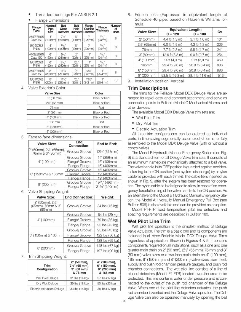
• Threaded openings Per ANSI B 2.1• Flange Dimensions
Electric Actuation Deluge 33 lbs (15 kg) 38 lbs (17 kg)
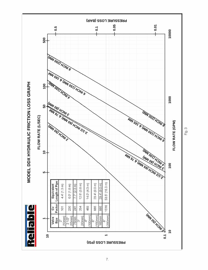
8. Friction loss (Expressed in equivalent length of Schedule 40 pipe, based on Hazen & Williams for-mula:
Valve Size:Equivalent Length:
CvC = 120 C = 100
2" (50mm) 4.4 ft (1,3 m) 3.1 ft (1,0 m) 1012½" (65mm) 6.0 ft (1,8 m) 4.3 ft (1,3 m) 236
76mm 7.7 ft (2,3 m) 5.5 ft (1,7 m) 2413" (80mm) 12.6 ft (3,8 m) 9.0 ft (2,7 m) 2544" (100mm) 14 ft (4,3 m) 10 ft (3,0 m) 469
165mm 29.4 ft (9,0 m) 20.9 ft (6,4 m) 8866" (150mm) 29.4 ft (9,0 m) 20.9 ft (6,4 m) 8868" (200mm) 53.5 ft (16,3 m) 38.1 ft (11,6 m) 1516
9. Installation position: Vertical
Trim DescriptionsThe trims for the Reliable Model DDX Deluge Valve are ar-
ranged for rapid, easy, and compact attachment, and serve as connection points to Reliable Model C Mechanical Alarms and other devices.
The available Model DDX Deluge Valve trim sets are:• Wet Pilot Trim• Dry Pilot Trim• Electric Actuation TrimAll three trim configurations can be ordered as individual
parts, in time-saving segmentally assembled kit forms, or fully assembled to the Model DDX Deluge Valve (with or without a control valve).
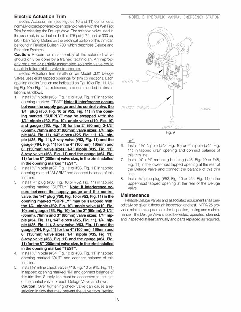
The Model B Hydraulic Manual Emergency Station (see Fig. 9) is a standard item of all Deluge Valve trim sets. It consists of an aluminum nameplate mechanically attached to a ball valve. The valve handle in its OFF position is guarded against acciden-tal turning to the ON position (and system discharge) by a nylon cable tie provided with each trim kit. The cable tie is inserted, as shown in Fig. 9, after the system has been restored for opera-tion. The nylon cable tie is designed to allow, in case of an emer-gency, forceful turning of the valve handle to the ON position. As an alternative to the Model B Hydraulic Manual Emergency Sta-tion, the Model A Hydraulic Manual Emergency Pull Box (see Bulletin 506) is also available and can be provided as an option.
Model F1-FTR fixed temperature pilot line detectors and spacing requirements are described in Bulletin 180.
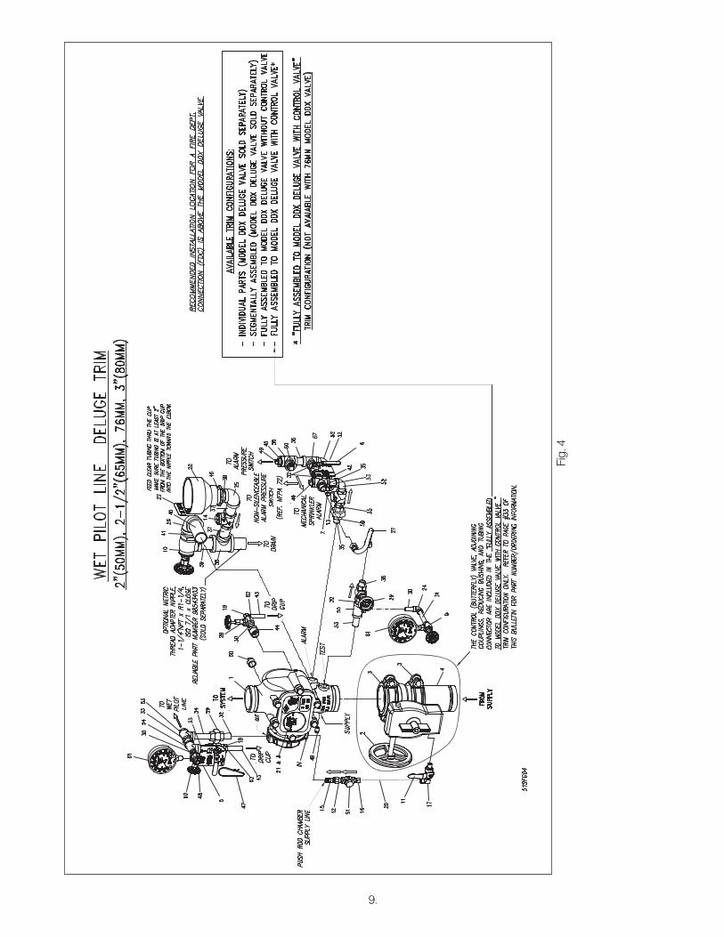
Wet Pilot Line TrimWet pilot line operation is the simplest method of Deluge
Valve Actuation. The trim is a basic one and its components are included in all other Reliable Model DDX Deluge Valve Trims regardless of application. Shown in Figures 4 & 5, it contains components required on all installations, such as a one and one quarter main drain on 2” (50 mm), 2½” (65 mm), 76 mm and 3” (80 mm) valve sizes or a two inch main drain on 4” (100 mm), 165 mm, 6” (150 mm) and 8” (200 mm) valve sizes, alarm test, supply and push rod chamber pressure gauges, and push rod chamber connections. The wet pilot line consists of a line of closed detectors (Model F1-FTR) located over the area to be protected. This line contains water under pressure and is con-nected to the outlet of the push rod chamber of the Deluge Valve. When one of the pilot line detectors actuates, the push rod chamber is vented and the Deluge Valve operates. The Del-uge Valve can also be operated manually by opening the ball
valve of the Model B Hydraulic Manual Emergency Station (see Fig. 9) or the optional Model A Hydraulic Manual Emergency Pull Box (see Reliable Bulletin 506).
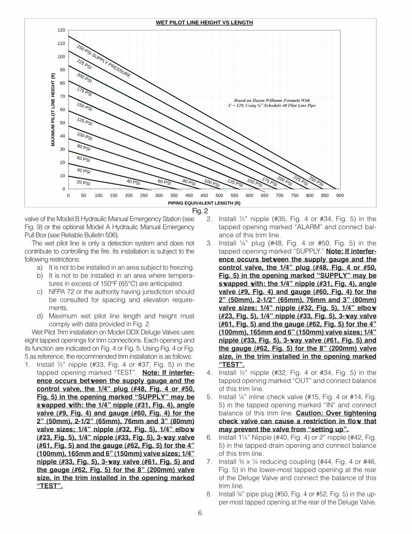
The wet pilot line is only a detection system and does not contribute to controlling the fire. Its installation is subject to the following restrictions:
a) It is not to be installed in an area subject to freezing.b) It is not to be installed in an area where tempera-
tures in excess of 150°F (65°C) are anticipated.c) NFPA 72 or the authority having jurisdiction should
be consulted for spacing and elevation require-ments.
d) Maximum wet pilot line length and height must comply with data provided in Fig. 2.
Wet Pilot Trim installation on Model DDX Deluge Valves uses eight tapped openings for trim connections. Each opening and its function are indicated on Fig. 4 or Fig. 5. Using Fig. 4 or Fig. 5 as reference, the recommended trim installation is as follows:1. Install ½” nipple (#33, Fig. 4 or #37, Fig. 5) in the
tapped opening marked “TEST”. Note: If interfer-ence occurs between the supply gauge and the control valve, the 1/4” plug (#48, Fig. 4 or #50, Fig. 5) in the opening marked “SUPPLY” may be swapped with: the 1/4” nipple (#31, Fig. 4), angle valve (#9, Fig. 4) and gauge (#60, Fig. 4) for the 2” (50mm), 2-1/2” (65mm), 76mm and 3” (80mm) valve sizes; 1/4” nipple (#32, Fig. 5), 1/4” elbow (#23, Fig. 5), 1/4” nipple (#33, Fig. 5), 3-way valve (#61, Fig. 5) and the gauge (#62, Fig. 5) for the 4” (100mm), 165mm and 6” (150mm) valve sizes; 1/4” nipple (#33, Fig. 5), 3-way valve (#61, Fig. 5) and the gauge (#62, Fig. 5) for the 8” (200mm) valve size, in the trim installed in the opening marked “TEST”.
2. Install ½” nipple (#35, Fig. 4 or #34, Fig. 5) in the tapped opening marked “ALARM” and connect bal-ance of this trim line.
3. Install ¼” plug (#48, Fig. 4 or #50, Fig. 5) in the tapped opening marked “SUPPLY.” Note: If interfer-ence occurs between the supply gauge and the control valve, the 1/4” plug (#48, Fig. 4 or #50, Fig. 5) in the opening marked “SUPPLY” may be swapped with: the 1/4” nipple (#31, Fig. 4), angle valve (#9, Fig. 4) and gauge (#60, Fig. 4) for the 2” (50mm), 2-1/2” (65mm), 76mm and 3” (80mm) valve sizes; 1/4” nipple (#32, Fig. 5), 1/4” elbow (#23, Fig. 5), 1/4” nipple (#33, Fig. 5), 3-way valve (#61, Fig. 5) and the gauge (#62, Fig. 5) for the 4” (100mm), 165mm and 6” (150mm) valve sizes; 1/4” nipple (#33, Fig. 5), 3-way valve (#61, Fig. 5) and the gauge (#62, Fig. 5) for the 8” (200mm) valve size, in the trim installed in the opening marked “TEST”.
4. Install ½” nipple (#32, Fig. 4 or #34, Fig. 5) in the tapped opening marked “OUT” and connect balance of this trim line.
5. Install ¼” inline check valve (#15, Fig. 4 or #14, Fig. 5) in the tapped opening marked “IN” and connect balance of this trim line. Caution: Over tightening check valve can cause a restriction in fl ow that may prevent the valve from “setting up”.
6. Install 1¼” Nipple (#40, Fig. 4) or 2” nipple (#42, Fig. 5) in the tapped drain opening and connect balance of this trim line.
7. Install ¾ x ¼ reducing coupling (#44, Fig. 4 or #46, Fig. 5) in the lower-most tapped opening at the rear of the Deluge Valve and connect the balance of this trim line.
8. Install ¾” pipe plug (#50, Fig. 4 or #52, Fig. 5) in the up-per-most tapped opening at the rear of the Deluge Valve.
7.
MO
DEL
DD
X H
YDR
AU
LIC
FR
ICTI
ON
LO
SS G
RA
PH
FLO
W R
ATE
(L/S
EC)
0.01
0.05
8INCH(200MM)
8INCH(200MM)
6INCH(150MM)&165MM
6INCH(150MM)&165MM
4INCH(100MM)
4INCH(100MM)
3INCH(80MM)
3INCH(80MM)
2-1/2INCH(65MM)&76MM
2-1/2INCH(65MM)&76MM
2 INCH (5
0 MM)
2INCH(50MM)
15
1050
100
500
0.1
0.5
PRESSURE LOSS (BAR)
0.1110
1010
010
0010
000
FLO
W R
ATE
(GPM
)
PRESSURE LOSS (PSI)
Fig.
3
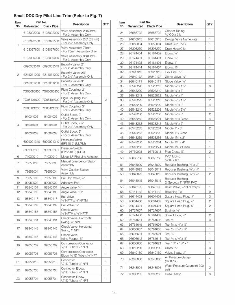
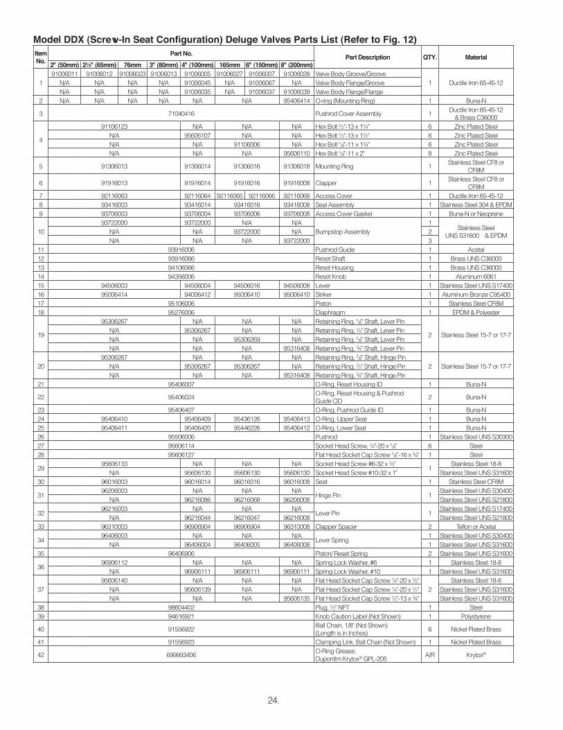
Item No.
Part No.Description QTY.
Galvanized Black Pipe
1
6103022000 6103022000Valve Assembly, 2" (50mm) - For 2" Assembly Only
16103022500 6103022500
Valve Assembly, 2½" (65mm) -For 2½" Assembly Only
6103027600 6103027600Valve Assembly, 76mm - For 76mm Assembly Only
6103030000 6103030000Valve Assembly, 3" (80mm) - For 3" Assembly Only
2
6990003549 6990003549Butterfly Valve, 2" -For 2" Assembly Only
16215051000 6215051000Butterfly Valve, 2½" - For 2½" Assembly Only
6215051200 6215051200Butterfly Valve, 3" - For 3" Assembly Only
3
7G05080800 7G05080800Rigid Coupling, 2" - For 2" Assembly Only
27G05101000 7G05101000Rigid Coupling, 2½" -For 2½" Assembly Only
7G05121200 7G05121200Rigid Coupling, 3" - For 3" Assembly Only
4
91004002 91004002Outlet Spool, 2" -For 2" Assembly Only
191004001 91004001Outlet Spool, 2½" - For 2½" Assembly Only
91004003 91004003Outlet Spool, 3" - For 3" Assembly Only
5 78653000 78653000Manual Emergency Station Assembly
Dry Pilot Line TrimDry pilot line operation is used in areas which are subject to
freezing conditions or to obtain installed sprinkler heights and pipe lengths greater than allowed for wet pilot line trim.
Dry pilot operation uses a pilot line of closed sprinklers (Model F1-FTR) containing air under pressure located in the area to be protected. This pressurized line is connected to a Model LP Dry Pilot Line Actuator. The dry pilot line actuator func-tions very much like a miniature dry pipe valve. In areas where moisture-laden air could cause freezing or other problems in the dry pilot line, the use of a cylinder of dry compressed gas such as nitrogen is suggested. Approved gas handling regula-tors and connections are then recommended. When one of the closed sprinklers on the dry pilot line actuates, the air pressure is reduced, thus opening the Model LP Dry Pilot Line Actuator, which releases the Deluge Valve. NFPA 72 or the Authority Hav-ing Jurisdiction should be consulted for spacing and elevation requirements of the pilot line sprinklers.
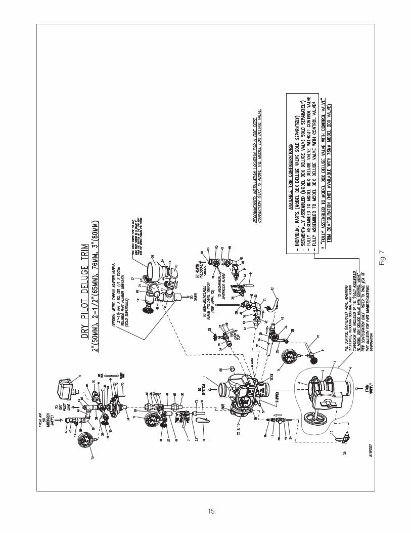
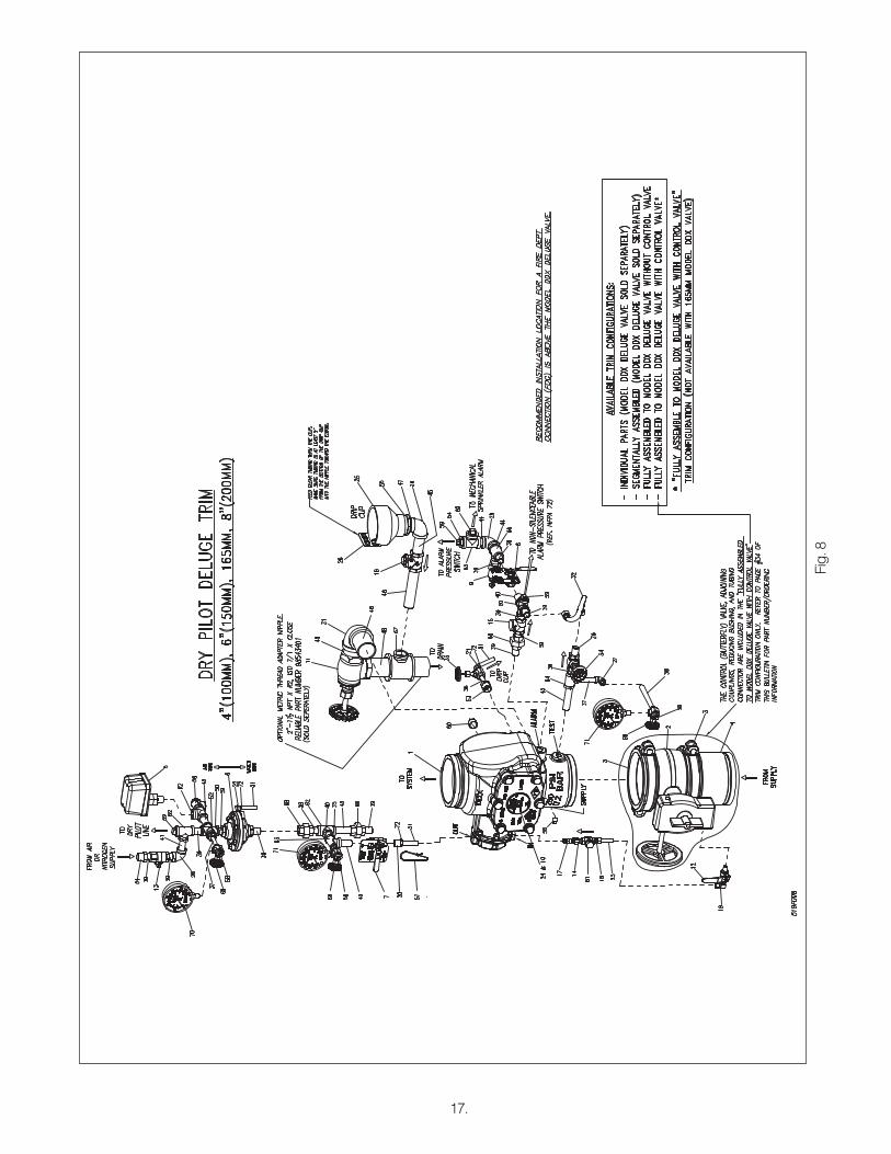
The Dry Pilot Line Trim, shown in Figures 7 and 8, includes gauges to read the air and water pressure, a low air pressure switch, a pressure relief valve, a Model LP Dry Pilot Line Actua-tor, and connections for the dry pilot line of detectors.
Dry Pilot Line Trim installation on Model DDX Deluge Valves uses eight tapped openings for trim connections. Each opening and its function are indicated on Fig. 7 and Fig. 8. Using Fig. 7 and Fig. 8 as reference, the recommended trim installation is as follows:1. Install ½” nipple (#39, Fig. 7 or #43, Fig. 8) in tapped
opening marked “TEST”. Note: If interference oc-curs between the supply gauge and the control valve, the 1/4” plug (#57, Fig. 7 or #58, Fig. 8) in the opening marked “SUPPLY” may be swapped with: the 1/4” nipple (#37, Fig. 7), angle valve (#11, Fig. 7) and gauge (#71, Fig. 7) for the 2” (50mm), 2-1/2” (65mm), 76mm and 3” (80mm) valve sizes; 1/4” nipple (#37, Fig. 8), 1/4” elbow (#27, Fig. 8), 1/4” nipple (#38, Fig. 8), 3-way valve (#69, Fig. 8) and the gauge (#71, Fig. 8) for the 4” (100mm), 165mm and 6” (150mm) valve sizes; 1/4” nipple (#38, Fig. 8), 3-way valve (#69, Fig. 8) and the gauge (#71, Fig. 8) for the 8” (200mm) valve size, in the trim installed in the opening marked “TEST”.
2. Install ½” nipple (#42, Fig. 7 or #39, Fig. 8) in tapped opening marked “ALARM” and connect balance of this trim line.
3. Install ¼” plug (#57, Fig. 7 or #58, Fig. 8) in tapped opening marked “SUPPLY.” Note: If interference occurs between the supply gauge and the control valve, the 1/4” plug (#57, Fig. 7 or #58, Fig. 8) in the opening marked “SUPPLY” may be swapped with: the 1/4” nipple (#37, Fig. 7), angle valve (#11, Fig. 7) and gauge (#71, Fig. 7) for the 2” (50mm), 2-1/2” (65mm), 76mm and 3” (80mm) valve sizes; 1/4” nipple (#37, Fig. 8), 1/4” elbow (#27, Fig. 8), 1/4” nipple (#38, Fig. 8), 3-way valve (#69, Fig. 8) and the gauge (#71, Fig. 8) for the 4” (100mm), 165mm and 6” (150mm) valve sizes; 1/4” nipple (#38, Fig. 8), 3-way valve (#69, Fig. 8) and the gauge (#71, Fig. 8) for the 8” (200mm) valve size, in
the trim installed in the opening marked “TEST”.4. Install ½” nipple (#38, Fig. 7 or #39, Fig. 8) in tapped
opening marked “OUT” and connect balance of this trim line.
5. Install ¼” inline check valve (#18, Fig. 7 or #17, Fig. 8) in tapped opening marked “IN” and connect bal-ance of this trim line. Caution: Over tightening check valve can cause a restriction in flow that may prevent the valve from “setting up”.
6. Install 1¼” Nipple (#47, Fig. 7) or 2” nipple (#48, Fig. 8) in tapped drain opening and connect balance of this trim line.
7. Install ¾” x ¼” reducing bushing (#52, Fig. 7 or #53, Fig. 8) in the lower-most tapped opening at the rear of the Deluge Valve and connect the balance of this trim line.
8. Install ¾” pipe plug (#59, Fig. 7 or #60, Fig. 8) in the upper-most tapped opening at the rear of the Deluge Valve.
Connect the air supply to the air inlet side of the Model LP Dry Pilot Line Actuator as shown in Fig. 7 or Fig. 8. Table A speci-fies the air pressure to be used in a dry pilot line. The level of air pressure is adjusted by removing the cap nut on the end of the Relief Valve (#55, Fig. 7 or #56, Fig. 8) and turning the now exposed slotted adjusting screw clockwise to increase pres-sure or counterclockwise to reduce it. Replace the cap nut after the correct pressure setting has been made at 5 psi above the maximum pilot line pressure required by Table A. An appropri-ate automatic pressure maintenance device must be used to safeguard against the Deluge Valve tripping due to air pressure leaks in the dry pilot line. See Bulletin 254 for pressure mainte-nance device information.
Install the dry pilot line as required. Wire the low air pressure switch (#5, Fig. 7 or #5, Fig. 8) to an annunciating device or con-trol panel. This low air pressure switch should be set to open at an air pressure which is slightly lower than the “Not Less Than” values found in Table A.
Table A
Water Pressurepsi (bar)
Pneumatic Pressure to be Pumped into Sprinkler System
Note: During system set-up, a higher pneumatic pressure may be required in order to properly set the Model LP Dry Pilot Line Actuator.
13.
Fig. 6
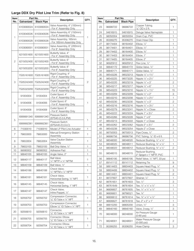
Item No.
Part No. DescriptionQty.
Required
1 94106936 Lower Housing 1
2 94106935 Upper Housing 1
3 96006905 Seat 1
4 92206311 Diaphragm 1
5 95106911 Facing Plate Assembly 1
6 96906311 Diaphragm Washer 1
7 94906406 Facing Plate Nut 1
8 95406901 Seat O-Ring 1
9 95606305 Bolt 6
10 96406902 Compression Spring 1
Maintenance – Model LP Dry Pilot Line ActuatorRefer to Figs. 6 & 14If water constantly flows through the Model LP Dry Pilot Line Actuator and into the drain, there is a leak in the seal of the Actuator’s seat.1. Close the main valve controlling water supply (Fig.
14) to the Dry Pipe Valve and close off the air/nitro-gen supply to the sprinkler system. Close valve A (Fig. 14).
2. Drop pressure in the system by opening the ¼” an-gle valve, valve H (Fig. 14), and remove the Actuator from the system.
3. Remove all six bolts (#9, Fig. 6) holding the Actuator together. Clean or replace the facing plate assembly (#5, Fig. 6), seat (#3, Fig. 6) and seat o-ring (#8, Fig. 6).
4. Reassemble the Actuator, using a torque of 8 ft-lbs on the facing plate nut (#7, Fig. 6) and 12 ft-lbs on the six bolts (#9, Fig. 6). Use a cross-tightening pat-tern. Reinstall the Actuator. Set up the Model DDX Deluge Valve as per the section “Resetting Model DDX Deluge Valve System”.
Model LP Dry Pilot Line Actuator Parts List P/N 71030010
14.
Item No.
Part No.Description QTY.
Galvanized Black Pipe
1
6103022000 6103022000Valve Assembly, 2" (50mm)- For 2" Assembly Only
16103022500 6103022500
Valve Assembly, 2½" (65mm)- For 2½" Assembly Only
6103027600 6103027600Valve Assembly, 76mm- For 76mm Assembly Only
6103030000 6103030000Valve Assembly, 3" (80mm)- For 3" Assembly Only
2
6990003549 6990003549Butterfly Valve, 2"- For 2" Assembly Only
16215051000 6215051000Butterfly Valve, 2½"- For 2½" Assembly Only
6215051200 6215051200Butterfly Valve, 3"- For 3" Assembly Only
3
7G05080800 7G05080800Rigid Coupling, 2"- For 2" Assembly Only
27G05101000 7G05101000Rigid Coupling, 2½"- For 2½" Assembly Only
7G05121200 7G05121200Rigid Coupling, 3"- For 3" Assembly Only
4
91004002 91004002Outlet Spool, 2"- For 2" Assembly Only
191004001 91004001Outlet Spool, 2½"- For 2½" Assembly Only
91004003 91004003Outlet Spool, 3"- For 3" Assembly Only
56999991340 6999991340
Pressure Switch(EPS40-2) (UL/FM)
16999992361 6999992361
Pressure Switch(EPSA40-2) (ULC)
6 71030010 71030010 Model LP Pilot Line Actuator 1
7 78653000 78653000Manual Emergency Station Assembly
Electric Actuation TrimElectric Actuation trim (see Figures 10 and 11) combines a
normally closed/powered-open solenoid valve with the Wet Pilot Trim for releasing the Deluge Valve. The solenoid valve used in the assembly is available in both a 175 psi (12,1 bar) or 300 psi (20,7 bar) rating. Details on the electrical portion of this trim can be found in Reliable Bulletin 700, which describes Deluge and Preaction Systems.Caution: Repairs or disassembly of the solenoid valve should only be done by a trained technician. An improp-erly repaired or partially assembled solenoid valve could result in failure of the valve to operate.
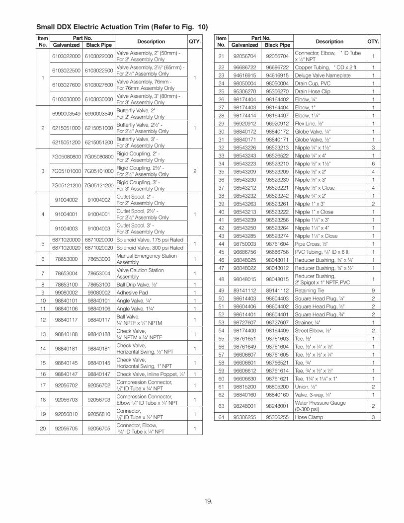
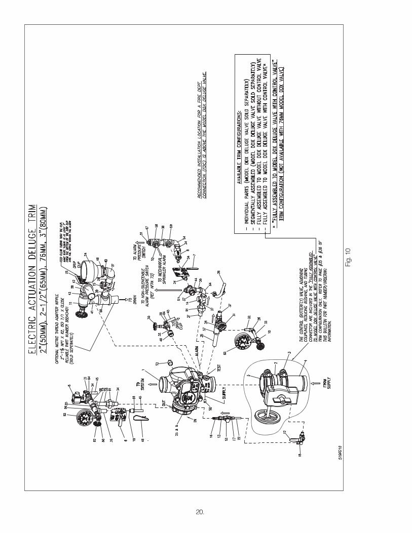
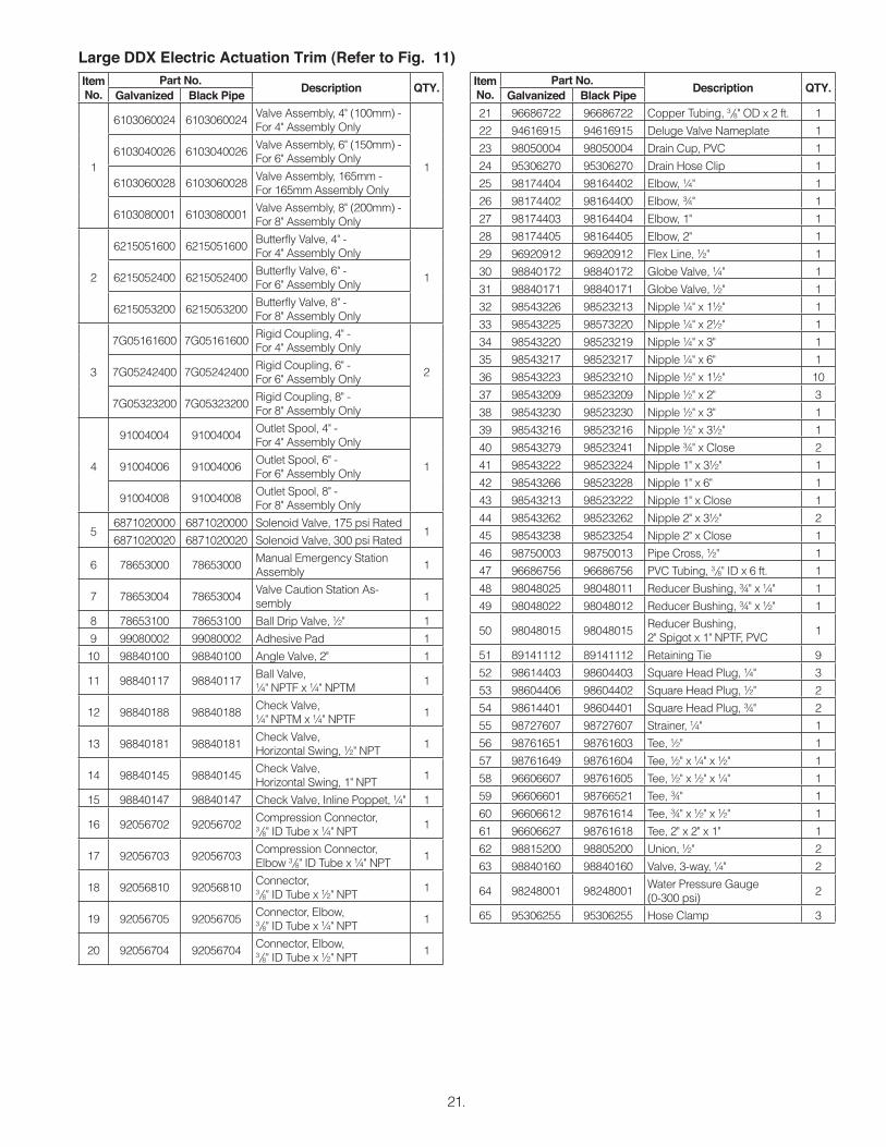
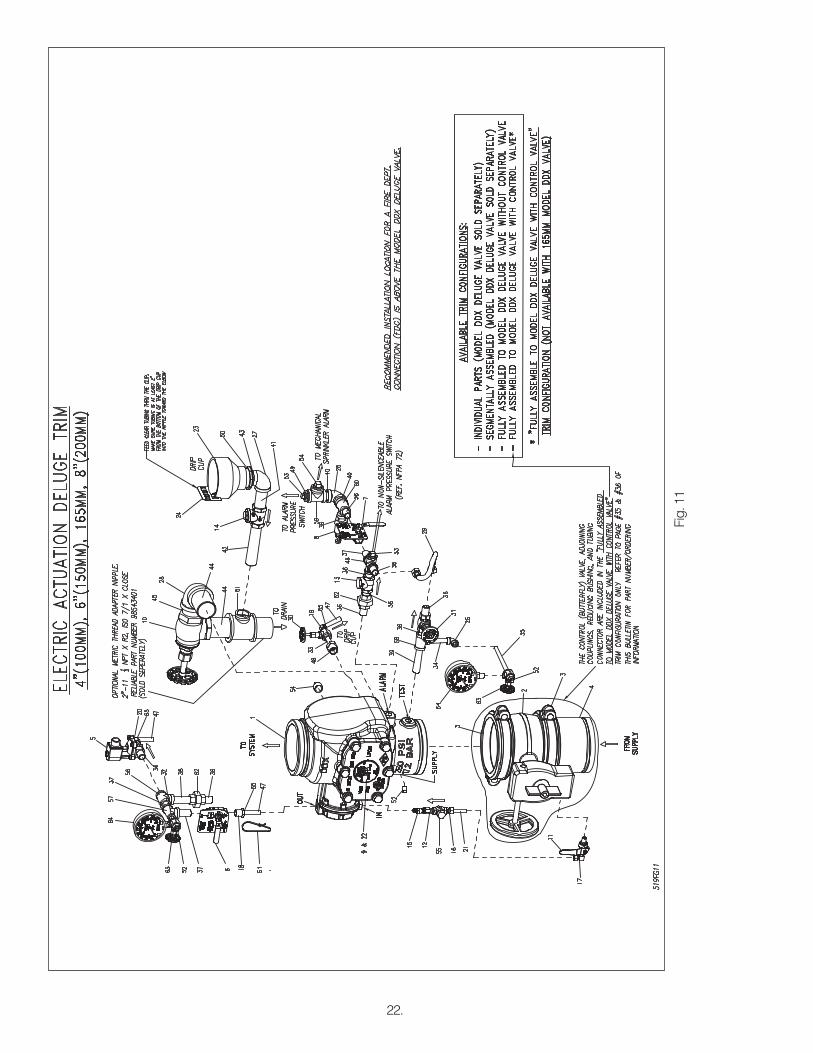
Electric Actuation Trim installation on Model DDX Deluge Valves uses eight tapped openings for trim connections. Each opening and its function are indicated on Fig. 10 or Fig. 11. Us-ing Fig. 10 or Fig. 11 as reference, the recommended trim instal-lation is as follows:1. Install ½” nipple (#35, Fig. 10 or #39, Fig. 11) in tapped
opening marked “TEST.” Note: If interference occurs between the supply gauge and the control valve, the 1/4” plug (#50, Fig. 10 or #52, Fig. 11) in the open-ing marked “SUPPLY” may be swapped with: the 1/4” nipple (#32, Fig. 10), angle valve (#10, Fig. 10) and gauge (#63, Fig. 10) for the 2” (50mm), 2-1/2” (65mm), 76mm and 3” (80mm) valve sizes; 1/4” nip-ple (#34, Fig. 11), 1/4” elbow (#25, Fig. 11), 1/4” nip-ple (#35, Fig. 11), 3-way valve (#63, Fig. 11) and the gauge (#64, Fig. 11) for the 4” (100mm), 165mm and 6” (150mm) valve sizes; 1/4” nipple (#35, Fig. 11), 3-way valve (#63, Fig. 11) and the gauge (#64, Fig. 11) for the 8” (200mm) valve size, in the trim installed in the opening marked “TEST”.
2. Install ½” nipple (#37, Fig. 10 or #36, Fig. 11) in tapped opening marked “ALARM” and connect balance of this trim line.
3. Install ¼” plug (#50, Fig. 10 or #52, Fig. 11) in tapped opening marked “SUPPLY.” Note: If interference oc-curs between the supply gauge and the control valve, the 1/4” plug (#50, Fig. 10 or #52, Fig. 11) in the opening marked “SUPPLY” may be swapped with: the 1/4” nipple (#32, Fig. 10), angle valve (#10, Fig. 10) and gauge (#63, Fig. 10) for the 2” (50mm), 2-1/2” (65mm), 76mm and 3” (80mm) valve sizes; 1/4” nip-ple (#34, Fig. 11), 1/4” elbow (#25, Fig. 11), 1/4” nip-ple (#35, Fig. 11), 3-way valve (#63, Fig. 11) and the gauge (#64, Fig. 11) for the 4” (100mm), 165mm and 6” (150mm) valve sizes; 1/4” nipple (#35, Fig. 11), 3-way valve (#63, Fig. 11) and the gauge (#64, Fig. 11) for the 8” (200mm) valve size, in the trim installed in the opening marked “TEST”.
4. Install ½” nipple (#34, Fig. 10 or #36, Fig. 11) in tapped opening marked “OUT” and connect balance of this trim line.
5. Install ¼” inline check valve (#16, Fig. 10 or #15, Fig. 11) in tapped opening marked “IN” and connect balance of this trim line. Supply line must be connected to the inlet of the control valve for each Deluge Valve as shown.Caution: Over tightening check valve can cause a re-striction in flow that may prevent the valve from “setting
11) in tapped drain opening and connect balance of this trim line.
7. Install ¾” x ¼” reducing bushing (#46, Fig. 10 or #48, Fig. 11) in the lower-most tapped opening at the rear of the Deluge Valve and connect the balance of this trim line.
8. Install ¾” pipe plug (#52, Fig. 10 or #54, Fig. 11) in the upper-most tapped opening at the rear of the Deluge Valve
MaintenanceReliable Deluge Valves and associated equipment shall peri-
odically be given a thorough inspection and test. NFPA 25 pro-vides minimum requirements for inspection, testing and mainte-nance. The Deluge Valve should be tested, operated, cleaned, and inspected at least annually and parts replaced as required.
Fig. 9
19.
Item No.
Part No.Description QTY.
Galvanized Black Pipe
1
6103022000 6103022000Valve Assembly, 2" (50mm) -For 2" Assembly Only
16103022500 6103022500
Valve Assembly, 2½" (65mm) -For 2½" Assembly Only
6103027600 6103027600Valve Assembly, 76mm -For 76mm Assembly Only
6103030000 6103030000Valve Assembly, 3" (80mm) -For 3" Assembly Only
2
6990003549 6990003549Butterfly Valve, 2" -For 2" Assembly Only
16215051000 6215051000Butterfly Valve, 2½" -For 2½" Assembly Only
6215051200 6215051200Butterfly Valve, 3" -For 3" Assembly Only
3
7G05080800 7G05080800Rigid Coupling, 2" -For 2" Assembly Only
27G05101000 7G05101000Rigid Coupling, 2½" -For 2½" Assembly Only
7G05121200 7G05121200Rigid Coupling, 3" -For 3" Assembly Only
4
91004002 91004002Outlet Spool, 2" -For 2" Assembly Only
191004001 91004001Outlet Spool, 2½" -For 2½" Assembly Only
91004003 91004003Outlet Spool, 3" -For 3" Assembly Only
N/A 96906111 96906111 96906111 Spring Lock Washer, #10 1 Stainless Steel UNS S31600
3795606140 N/A N/A N/A Flat Head Socket Cap Screw ¼"-20 x ½"
2Stainless Steel 18-8
N/A 95606139 N/A N/A Flat Head Socket Cap Screw ¼"-20 x ½" Stainless Steel UNS S31600N/A N/A N/A 95606135 Flat Head Socket Cap Screw ½"-13 x ¾" Stainless Steel UNS S31600
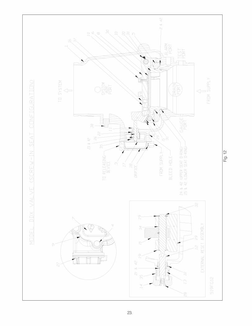
Resetting Model DDX Deluge Valve SystemsRefer to Figs. 7, 8, 12, 13 & 14.1. Close the valve controlling water supply to the Del-
uge Valve and close valve A (Fig. 14).2. Open main drain valve B (Fig. 14) and drain system.3. Open all drain valves and vents at low points through-
out the system, closing them when flow of water has stopped. Open valve D (Fig. 14).
4. With valve G (Fig. 14) open, push in the plunger of ball drip valve E (Fig. 14), forcing the ball from its seat to verify that there is atmospheric pressure in-side the main valve chamber.
5. Push in and rotate external reset knob (#14, Fig. 12 or #38, Fig. 13) clockwise, until you hear a distinct noise indicating that the clapper has reset.
6. Inspect and replace any portion of the detection sys-tem subjected to fire conditions.
7. Open valve A (Fig. 14) and allow water to fill the push rod chamber. Close valve D (Fig. 14).
8. Bleed all air from the actuation piping.A. Wet Pilot Trim—bleed the entire wet pilot line until all
air is removed at the most remote sprinkler.B. Electric Actuation Trim—open the solenoid valve by
operating a detector or an electric manual emer-gency station. While water is flowing through the so-lenoid valve, cause it to close. Refer to Bulletin 700, “Special Hazards & Special Systems” for details.
C. Dry Pilot Trim—open valve D (Fig. 14) allowing wa-ter to flow through the pilot line actuator. When all air has been expelled from the release line, and there is a solid flow of water into the drain cup J (Fig. 14), apply compressed air or nitrogen through the pressure maintenance device to close the pilot line actuator. Subsequently, close valve D (Fig. 14) and adjust the air or nitrogen pressure to the appropriate value in Table A as indicated on air pressure gauge (#71, Fig. 7 or #71, Fig. 8).
9. Check that valves D (Fig. 14) and F (Fig. 14) are closed and that valve G is open (Fig. 14). Open slightly the valve controlling water supply to the Del-uge Valve, closing the main drain valve B (Fig. 14) when water flows. Observe if water leaks through ball drip valve E (Fig. 14), into drain cup J (Fig. 14), (Be sure that valve G (Fig. 14) is open). If no leak occurs the water seat is tight. Open slowly but fully the valve controlling water supply to the Deluge Valve. Verify that it is fully opened and properly monitored.
10. Valve A (Fig. 14) must remain open when the Deluge Valve has been reset, to maintain water pressure in the push rod chamber.
11. Verify that the Model B Manual Emergency Station, valve D (Fig. 14) is sealed in the OFF position with the appropriate nylon tie.
Inspection and TestingRefer to Figs. 12, 13 & 14.1. Water supply — be sure the valves controlling wa-
ter supply to the Deluge Valve are opened fully and properly monitored.
2. Alarm line — be sure that valve G (Fig. 14) is opened and remains in this position.
3. Other trimming valves — check that valve A (Fig. 14) is open, as well as all of the pressure gauge’s ¼“ 3-way valves. Valves D, F, & H (Fig. 14) should be closed.
4. Ball drip valve E (Fig. 14) — Make sure valve G (Fig. 14) is open. Push in on the plunger to be sure ball check is off its seat. If no water appears, the Del-uge Valve’s water seat is tight. Inspect the bleed hole (see Fig. 12 of Fig. 13) on the underside of the push rod chamber for leakage.
5. Dry pilot trim — check air gauge pressure for con-formance to Table A.
6. Releasing device — check outlet of the releasing device (i.e., the dry pilot line actuator, solenoid valve, or the hydraulic manual emergency station) for leak-age. Also verify that tubing drain lines from releasing devices are not pinched or crushed which could pre-vent proper releasing of the Deluge Valve.
7. Testing alarms — Make sure valve G (Fig. 14) is open. Open valve F (Fig. 14) permitting water from the supply to flow to the electric sprinkler alarm switch and to the mechanical sprinkler alarm (water motor). After testing, close this valve securely. Push in on the plunger of ball drip valve E (Fig. 14) until all of the water has drained from the alarm line.
8. Operation test — Open the Model B Manual Emer-gency Station, valve D (Fig. 14).Note: An operational test will cause the Deluge Valve to open and flow water into the sprinkler system.
9. Secure the Model B Manual Emergency Station, valve D (Fig. 14), in the OFF position with nylon tie after Deluge Valve is reset.
Testing Detection System Without OperatingDeluge ValveRefer to Figs. 7, 8 & 14.1. Close the valve controlling water supply to Deluge
Valve and open the main drain valve B (Fig. 14).2. Verify that valve A (Fig. 14) is open, allowing water to
enter the push rod chamber.3. Operate detection system —
A. Wet Pilot Trim — open Model B Manual Emergen-cy Station, valve D (Fig. 14).
B. Dry Pilot Trim — directly above the Model LP Dry Pilot Line Actuator, remove the ¼” pipe plug (#58, Fig. 7 or #59, Fig. 8) and open the ¼” three-way valve (#70, Fig. 7 or #70, Fig. 8).
C. Electric Actuation — refer to Bulletin 700.4. Operation of the detection system must result in a
sudden drop of water pressure in the push rod cham-ber.
5. Reset detection system — reverse operations per-formed in step three above and then proceed ac-cording to the directions listed in the “Resetting Mod-el DDX Deluge Valve Systems” section of this bulletin for resetting the Deluge Valve.
27.
28.
Draining Excess/Condensate Water From SystemRefer to Fig. 141. Close the valve controlling water supply to Deluge
Valve. Also close valve A and open main drain valve B.
2. Open condensate drain valve H until all water has drained. Close valve H.
3. Close main drain valve B. If system contains pressur-ized air, allow air pressure to come back up to speci-fication (see table A). Open valve A and the valve controlling the water supply to the Deluge Valve.
shown) not operating: This is most likely caused by a clogged screen in the strainer of the water motor. Proceed as follows: Remove plug from the strainer. Remove and clean the screen. Replace the screen and the plug, and then tighten securely (Ref. Bulletin 613).
2. Leakage out of the ball drip valve E (Fig. 14).a. Water leakage due to water column in deluge
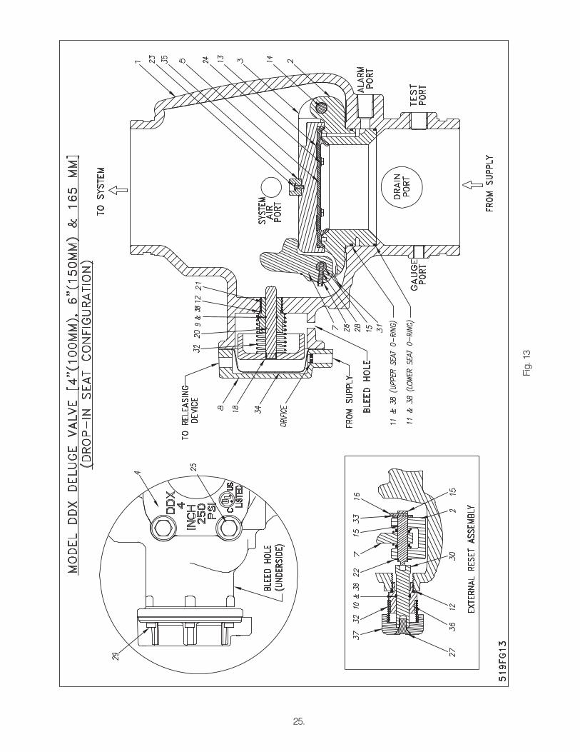
systems:This condition can be caused by leakage past the system side of the Model DDX Deluge Valve’s seal assembly (#8, Fig. 12 or #5, Fig. 13). Be sure that this surface is free of any type of debris. To eliminate leakage due to water column in a deluge system, refer to the section in this bulletin marked “Drain-ing Excess/Condensate Water From System”. If the problem continues proceed to the following section.
b. Leakage, air or water from the ball drip valve, E (Fig. 14):If system air is leaking out the ball drip valve, the problem is either damage to the airside of the Mod-el DDX Deluge Valve’s seal assembly (#8, Fig. 12 or #5, Fig. 13), seat (#29, Fig. 12 or #2, Fig. 13), the upper seat o-ring(#23, Fig. 12 or #11, Fig. 13) or, on the 8” (200 mm) valve size only, the mounting ring o-ring (#2, Fig. 12). If supply water is leaking out the ball drip valve, the problem could be caused by damage to the Model DDX Deluge Valve’s seal assembly (#8, Fig. 12 or #5, Fig. 13), seat (#29, Fig. 12 or #2, Fig. 13), or lower seat O-ring (#24, Fig. 12 or #11, Fig. 13). The following section provides instructions to correct both conditions:A) Shut down the valve controlling the water sup-
ply to the Deluge Valve and open the 1¼” main drain valve on the 2” (50mm), 2½” (65mm), 76mm and 3” (80mm) valve sizes or the 2” main drain valve on the 4” (100mm), 165mm, 6” (150mm) and 8” (200mm) valve sizes, valve B (Fig. 14). Open the water column drain valve H (Fig. 14). Close the pushrod chamber supply valve A (Fig. 14) and open the Model B Manual Emergency Station, valve D (Fig. 14).
B) Remove the Deluge Valve’s front (handhold) cover (#7, Fig. 12 or #4, Fig. 13) and inspect the
seat (#29, Fig. 12 or #2, Fig. 13), clapper (#6, Fig. 12 or #3, Fig. 13), and seal assembly (#8, Fig. 12 or #5, Fig. 13) for damage. If inspection indicates damage to the seal assembly (#8, Fig. 12 or #5, Fig. 13), replace as follows:For Valve Sizes: 2” (50mm), 2½” (65mm), 76mm, 3” (80mm), 8” (200mm) and 4” (100mm), 6” (150mm) & 165mm with Screw-In Seat only, Refer to Fig. 7, Fig. 8 & Fig. 12:Remove the bumpstop nuts (#10, Fig. 12) and remove the seal assembly (#8, Fig. 12). Install a new seal assembly (#8, Fig. 12) and thread the bumpstop nuts (#10, Fig. 12) onto the threaded studs of the seal assembly (#8, Fig. 12) and tighten finger tight plus ¼ to ½ turn. If inspec-tion indicates damage to the clapper (#6, Fig. 12) only, then the clapper subassembly can be removed as follows:At the rear of the valve, disconnect the water column drain trim section starting with the el-bow connector (#22, Fig. 7 or #21, Fig. 8). Then remove the ¼” globe valve (#33, Fig. 7 or #33, Fig. 8), followed by the ¾”x¼” reducing bushing (#52, Fig. 7 or #53, Fig. 8). Remove the retaining ring (condensate drain side for 2” (50mm), 2½” (65mm), 3” (80mm), 76mm and 8” (200mm) valve sizes or hand hole cover side for 4” (100mm), 6” (150mm) and 165mm valve sizes) from the clapper hinge pin (#30, Fig. 12) and push this pin through the hand hole open-ing (for 2” (50mm), 2½” (65mm), 3” (80mm), 76mm and 8” (200mm) valve sizes or conden-sate drain side for 4” (100mm), 6” (150mm) and 165mm valve sizes) and remove the clapper subassembly. Replace the seal assembly as described previously. Inspect the clapper (#6, Fig. 12) visually before reinstalling. Reinstall in the reverse order making sure the clapper spacers are in their proper position. If the seat (#29, Fig. 12) is damaged or it is suspected that the leakage is through the lower O-ring (#24, Fig. 12), the seat-clapper subassembly is eas-ily removed as a unit as follows:Using Reliable P/N 6881603000 Seat Wrench for 2” (50mm), 2½” (65mm), 76mm and 3” (80mm) valve sizes, Reliable P/N 6881604000 for 4” (100mm) valve size, Reliable P/N 6881606000 for the 6” (150mm) and 165mm valve sizes or Reliable P/N 6881608000 Seat Wrench for 8” (200mm) valve size, remove the seat by unscrewing. This will loosen the seat-clapper-mounting ring subassembly. Reach into the valve and grasp the seat and remove it from the valve. Then remove the clapper-mounting ring subassembly from the valve. Visually examine all components of the seat-clapper-mounting ring subassembly replacing any component that appears damaged. New O-rings (#23 & #24, Fig. 12 and #2, Fig. 12 (8”
(200mm) valve size only)) should always be used for reassembly.For Valve Sizes: 4” (100mm), 165mm, 6” (150mm) with Drop-In Seat Confi guration only, Refer to Fig. 8 and Fig. 13:At the rear of the valve, disconnect the water column drain trim section starting with the el-bow connector (#21, Fig. 8). Then remove the ¼” angle globe (#33, Fig. 8), followed by the ¾”x¼” reducing bushing (#53, Fig. 8). Remove the retaining ring (hand hole cover side) from the clapper hinge pin (#14, Fig. 13) and push this pin through the condensate drain port and remove the clapper subassembly. Remove the four retaining screws (#24, Fig. 13) holding the seal faceplate assembly (#5, Fig. 13). In-spect the clapper (#3, Fig. 13) visually before installing. Apply a small amount of silicone based lubricant to the four retaining screws. Install a new seal faceplate assembly. Torque the retaining screws to approximately 40 inch-pounds and reassemble. If the seat (#2, Fig. 13) is damaged or it is suspected that the leakage is through the lower o-ring (#11, Fig. 13), the seat-clapper subassembly is easily re-moved as a unit as follows:Using a 5/16” Allen wrench, remove the two 3/8” NPT pipe plugs (#19, (not shown) Fig. 13) located on the side chamber side of the Model DDX deluge valve. The seat-clapper subas-sembly is retained by two locking pins (#17, (not shown) Fig. 13). The centers of these pins have a ¼”-20 threaded hole. Remove the two locking pins by engaging them with a ¼”-20 screw and pulling them out (the two locking pins are not externally threaded, so turning them with the attached ¼”-20 screw or thread-ed rod is not recommended. A proven method is to use ¼”-20 threaded rod with a locknut on the unassembled end. Grab hold of the locknut with a pliers or vise-grips and tap the pliers or vise-grips in the direction away from the Deluge Valve. Doing so should pull the locking pins out of the Deluge Valve. With the clapper (#3, Fig. 13) in the closed position (not latched), dis-lodge the clapper-seat subassembly from the valve body by inserting two slotted screwdriv-ers under the lever and clapper mounting ears and pry up until the clapper-seat subassembly is free from its bore. Reach into the valve and grasp the clapper-seat subassembly from the sides. Making sure the clapper is in the closed position (see Fig. 1), lift up and rotate the clap-per-seat sub assembly clockwise 90 degrees so that the lever side of the assembly is fac-ing up towards the outlet of the deluge valve. Next, rotate the clapper-seat sub assembly 90 degrees about the centerline of the valve so that the clapper is facing the hand hole open-
29.
ing and the lever is still facing the outlet of the deluge valve.. Then rotate the clapper-seat sub assembly 90 degrees, so that the clapper is now facing the outlet of the deluge valve and the lever is now facing the back of the valve. Pull the clapper-seat sub assembly out through the hand hole opening by the hinge pin side. Rotating the seat-clapper subassembly up as it is being removed will help it slide out more easily since the lever will prohibit it from sliding straight out. Visually examine all components of the clapper-seat subassembly replacing any component that appears damaged. New o-rings (#11, Fig. 13) should always be used for reassembly.Reassembly:For Valve Sizes: 2” (50mm), 2½” (65mm), 76mm, 3” (80mm), 8” (200mm) and 4” (100mm), 6” (150mm) & 165mm with Screw-In Seat Confi guration only, Refer to Fig. 12:Clean the bore of the valve body. Lubricate the bore with O-ring grease. Lubricate and install the O-rings (#23 & #24, Fig. 12) onto the seat. Lubricate and install the mounting ring o-ring (#2, Fig. 12) into the body (8” (200mm) valve size only). Insert the clapper-mounting ring subassembly into the handhold opening of the Deluge Valve using caution to not damage or dislodge the mounting ring o-ring (#2, Fig. 12)(8” (200mm) valve size only). Align the mount-ing ring so that the Lever (#15, Fig. 12) is near the pushrod (#25, Fig. 12) and the mounting ring (#5, Fig. 12) “ears” are between the tabs of the valve body (#1, Fig. 12). Insert the seat (#29, Fig. 12) into the valve body (#1, Fig. 12) and through the clapper-mounting ring subas-sembly. Start to tread the seat (#29, Fig. 12) into the body by hand, then tighten the seat (#29, Fig. 12) with Reliable P/N 6881603000 Seat Wrench for 2” (50mm), 2½” (65mm), 76mm and 3” (80mm) valve sizes , Reliable P/N 6881604000 Seat Wrench for 4” (100mm) valve size, Reliable P/N 688106000 Seat Wrench for 6” (150mm and 165mm valve sizes or Reliable P/N 6881608000 Seat Wrench for 8” (200mm) valve size until it bottoms out on the mounting ring (#5, Fig. 12).Verify that the seat-clapper-mounting ring subassembly is in the fully down position between the tabs of the body, and check to see that the lever (#15, Fig. 12) lines up with the push rod (#25, Fig. 12). Loosen and reassemble if necessary. Reassemble the handhold cover (#7, Fig. 12) and set up the Model DDX Deluge Valve as per the section “Resetting Model DDX Deluge Valve Systems.”For Valve Sizes: 4” (100mm), 165mm, 6” (150mm) with Drop-In Seat Confi guration only, Refer to Fig. 13:It is likely that the lower seat o-ring (#11, Fig. 13)
30.
has remained at the bottom of the Deluge Valve body’s bore. Discard this o-ring and clean the bore. Lubricate the bore with o-ring grease and place the lower o-ring on the step at the bottom of the bore, verifying that it is in full contact with the bore. Lubricate the bottom step and upper o-ring (#11, Fig. 13) of the refurbished clapper-seat subassembly. Insert the clapper-seat sub assembly into the hand hole opening, lever (#7, Fig. 13) first and rotating the clapper-seat subassembly until the lever faces the outlet of the deluge valve. Next rotate the clapper-seat subassembly 90 degrees about the center axis of the valve until the bottom of the clapper-seat sub assembly faces the pushrod (#20, Fig. 13). Then rotate the clapper-seat subassembly 90 degrees counterclockwise so that the clapper (#3, Fig. 13) is facing the outlet of the deluge valve and the lever (#7, Fig. 13) is facing the pushrod (#20, Fig. 13). Once the clapper seat subassembly is in this position simply slide the assembly into the bore of the valve, making sure it is straight to avoid binding of the seat in the bore. Slightly twisting the assembly will assist in getting the clapper-seat subassem-bly properly seated. Once it is verified that the clapper-seat sub assembly is in the fully down position and the lever (#7, Fig. 13) is aligned with the pushrod (#20, Fig. 13), clean and lubri-cate the two locking pins (#17, (not shown) Fig. 13) with o-ring lubricant. Slide the two locking pins into the deluge valve body to lock the seat in place. Slightly twisting and pressing down on the clapper-seat subassembly will help the pins to slide in more easily. Then reinstall the 3/8” NPT pipe plugs (#19, (not shown) Fig. 13). Reassemble the hand hole cover (#4, Fig. 13) and set up the Model DDX Deluge Valve as per the section “Resetting Model DDX Deluge Valve Systems”.
3. Leakage out of the push rod chamber vent hole:A small bleed hole is located on the underside of the push rod chamber (see Fig. 12 or Fig. 13). If there is air or water leakage coming out of this hole, do the following:a) Shut down the valve controlling water supply to the
Deluge Valve. Relieve the inlet pressure by opening the 1¼” main drain valve on the 2” (50mm), 2½” (65mm), 76mm and 3” (80mm) valve sizes or the 2” main drain valve on the 4” (100mm), 165mm, 6” (150mm) and 8” (200mm) valve sizes, valve B (Fig. 14). Close valve A (Fig. 14) that supplies water to the push rod chamber, and open the Model B Man-ual Emergency Station, valve D (Fig. 14).
b) Remove the trim at the unions nearest to the push rod chamber cover (#3, Fig. 12 or #8, Fig. 13).
c) Take the push rod chamber cover (#3, Fig. 12 or #8, Fig. 13) off by removing the six retaining screws (#26, Fig. 12 or #29, Fig. 13).
CONDITION ONE (Water coming out of the bleed hole):Water coming out of the bleed hole is caused by a leaking diaphragm (#18, Fig. 12 or #34, Fig. 13). Visually inspect the push rod chamber cover (#3, Fig. 12 or #8, Fig. 13), piston (#17, Fig. 12 or #18, Fig. 13 and bore of the body (#1, Fig. 12 or #1, Fig. 13) to determine what could have damaged the diaphragm and correct. Install a new diaphragm. NOTE: The diaphragm has two different surfaces; it is not bi-directional. It will fail if installed backwards! Roll the diaphragm so that the smooth surface (the pressure side) conforms to the inside of the push rod chamber cover and reassemble the six retain-ing screws (#26, Fig. 12 or #29, Fig. 13) with an in-stallation torque of 15 foot-pounds. Set up the Mod-el DDX Deluge Valve as per the section “Resetting Model DDX Deluge Valve Systems.”CONDITION TWO (System Air coming out of the bleed hole):System air coming out of the bleed hole is caused by a defective O-ring assembled to the push rod guide (#11, Fig. 12 or #21, Fig. 13). Remove the pis-ton-push rod subassembly, push rod spring (#34, Fig. 12 or #32, Fig. 13), and push rod guide (#11, Fig. 12 or #21, Fig. 13). Verify by hand turning, that the push rod cannot be unscrewed from the piston. Replace all O-rings and the push rod guide (#21, #22 and #11, Fig. 12 or #9, #12 and #21, Fig.13). The correct installation torque for the pushrod guide is 35 inch-pounds. CAUTION: Do not over tighten the push rod guide. Reassemble the components that were initially removed. Re-install the diaphragm (#18, Fig. 12 or #34, Fig. 13) if it appears to be in good shape, otherwise, replace it also. NOTE: The diaphragm has two different surfaces; it is not bi-directional.It will fail if installed backwards! Roll the diaphragm so that the smooth surface (the pressure side) con-forms to the inside of the push rod chamber cover and reassemble the six retaining screws (#26, Fig. 12 or #29, Fig. 13) with an installation torque of 15 foot-pounds. Set up the Model DDX Deluge Valve as per the section “Resetting Model DDX Deluge Valve Systems.”
31.
Fig. 14
32.
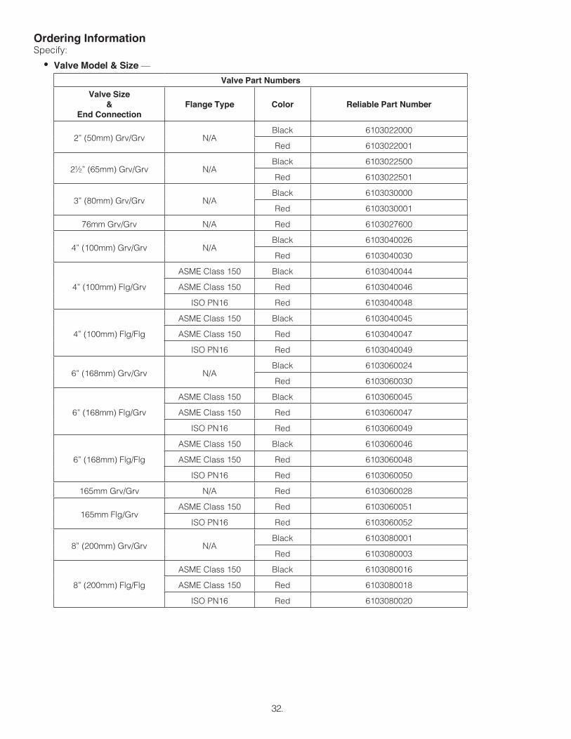
Ordering InformationSpecify:
• Valve Model & Size —
Valve Part Numbers
Valve Size&
End ConnectionFlange Type Color Reliable Part Number
2” (50mm) Grv/Grv N/ABlack 6103022000
Red 6103022001
2½” (65mm) Grv/Grv N/ABlack 6103022500
Red 6103022501
3” (80mm) Grv/Grv N/ABlack 6103030000
Red 6103030001
76mm Grv/Grv N/A Red 6103027600
4” (100mm) Grv/Grv N/ABlack 6103040026
Red 6103040030
4” (100mm) Flg/Grv
ASME Class 150 Black 6103040044
ASME Class 150 Red 6103040046
ISO PN16 Red 6103040048
4” (100mm) Flg/Flg
ASME Class 150 Black 6103040045
ASME Class 150 Red 6103040047
ISO PN16 Red 6103040049
6” (168mm) Grv/Grv N/ABlack 6103060024
Red 6103060030
6” (168mm) Flg/Grv
ASME Class 150 Black 6103060045
ASME Class 150 Red 6103060047
ISO PN16 Red 6103060049
6” (168mm) Flg/Flg
ASME Class 150 Black 6103060046
ASME Class 150 Red 6103060048
ISO PN16 Red 6103060050
165mm Grv/Grv N/A Red 6103060028
165mm Flg/GrvASME Class 150 Red 6103060051
ISO PN16 Red 6103060052
8” (200mm) Grv/Grv N/ABlack 6103080001
Red 6103080003
8” (200mm) Flg/Flg
ASME Class 150 Black 6103080016
ASME Class 150 Red 6103080018
ISO PN16 Red 6103080020
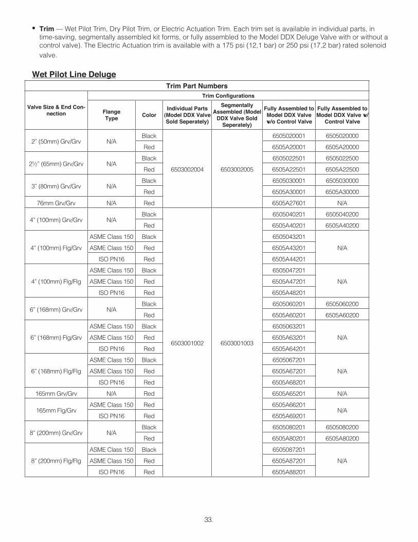
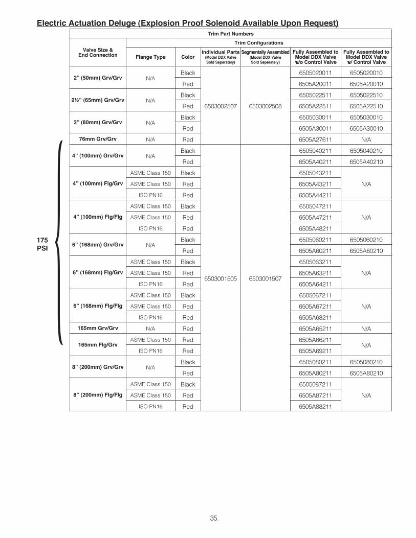
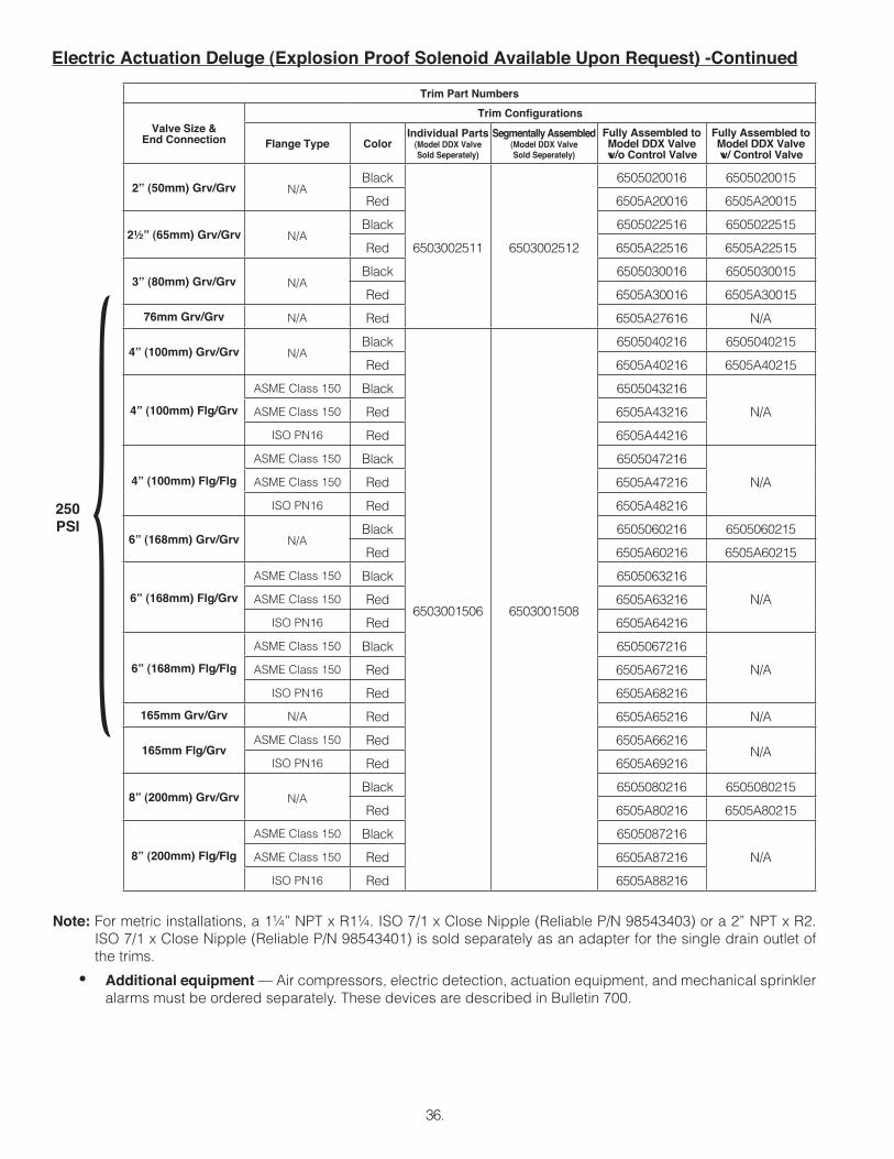
• Trim — Wet Pilot Trim, Dry Pilot Trim, or Electric Actuation Trim. Each trim set is available in individual parts, in time-saving, segmentally assembled kit forms, or fully assembled to the Model DDX Deluge Valve with or without a control valve). The Electric Actuation trim is available with a 175 psi (12,1 bar) or 250 psi (17,2 bar) rated solenoid valve.
Wet Pilot Line DelugeTrim Part Numbers
Valve Size & End Con-nection
Trim Confi gurations
FlangeType
ColorIndividual Parts
(Model DDX Valve Sold Seperately)
SegmentallyAssembled (Model
DDX Valve Sold Seperately)
Fully Assembled to Model DDX Valve w/o Control Valve
Fully Assembled to Model DDX Valve w/o Control Valve
Fully Assembled to Model DDX Valve w/ Control Valve
2” (50mm) Grv/Grv N/ABlack
6503002511 6503002512
6505020016 6505020015
Red 6505A20016 6505A20015
2½” (65mm) Grv/Grv N/ABlack 6505022516 6505022515
Red 6505A22516 6505A22515
3” (80mm) Grv/Grv N/ABlack 6505030016 6505030015
Red 6505A30016 6505A30015
76mm Grv/Grv N/A Red 6505A27616 N/A
4” (100mm) Grv/Grv N/ABlack
6503001506 6503001508
6505040216 6505040215
Red 6505A40216 6505A40215
4” (100mm) Flg/Grv
ASME Class 150 Black 6505043216
N/AASME Class 150 Red 6505A43216
ISO PN16 Red 6505A44216
4” (100mm) Flg/Flg
ASME Class 150 Black 6505047216
N/AASME Class 150 Red 6505A47216
ISO PN16 Red 6505A48216
6” (168mm) Grv/Grv N/ABlack 6505060216 6505060215
Red 6505A60216 6505A60215
6” (168mm) Flg/Grv
ASME Class 150 Black 6505063216
N/AASME Class 150 Red 6505A63216
ISO PN16 Red 6505A64216
6” (168mm) Flg/Flg
ASME Class 150 Black 6505067216
N/AASME Class 150 Red 6505A67216
ISO PN16 Red 6505A68216
165mm Grv/Grv N/A Red 6505A65216 N/A
165mm Flg/GrvASME Class 150 Red 6505A66216
N/AISO PN16 Red 6505A69216
8” (200mm) Grv/Grv N/ABlack 6505080216 6505080215
Red 6505A80216 6505A80215
8” (200mm) Flg/Flg
ASME Class 150 Black 6505087216
N/AASME Class 150 Red 6505A87216
ISO PN16 Red 6505A88216
Note: For metric installations, a 1¼” NPT x R1¼. ISO 7/1 x Close Nipple (Reliable P/N 98543403) or a 2” NPT x R2. ISO 7/1 x Close Nipple (Reliable P/N 98543401) is sold separately as an adapter for the single drain outlet of the trims.
• Additional equipment — Air compressors, electric detection, actuation equipment, and mechanical sprinkler alarms must be ordered separately. These devices are described in Bulletin 700.
Electric Actuation Deluge (Explosion Proof Solenoid Available Upon Request) -Continued
36.
250PSI {
37.
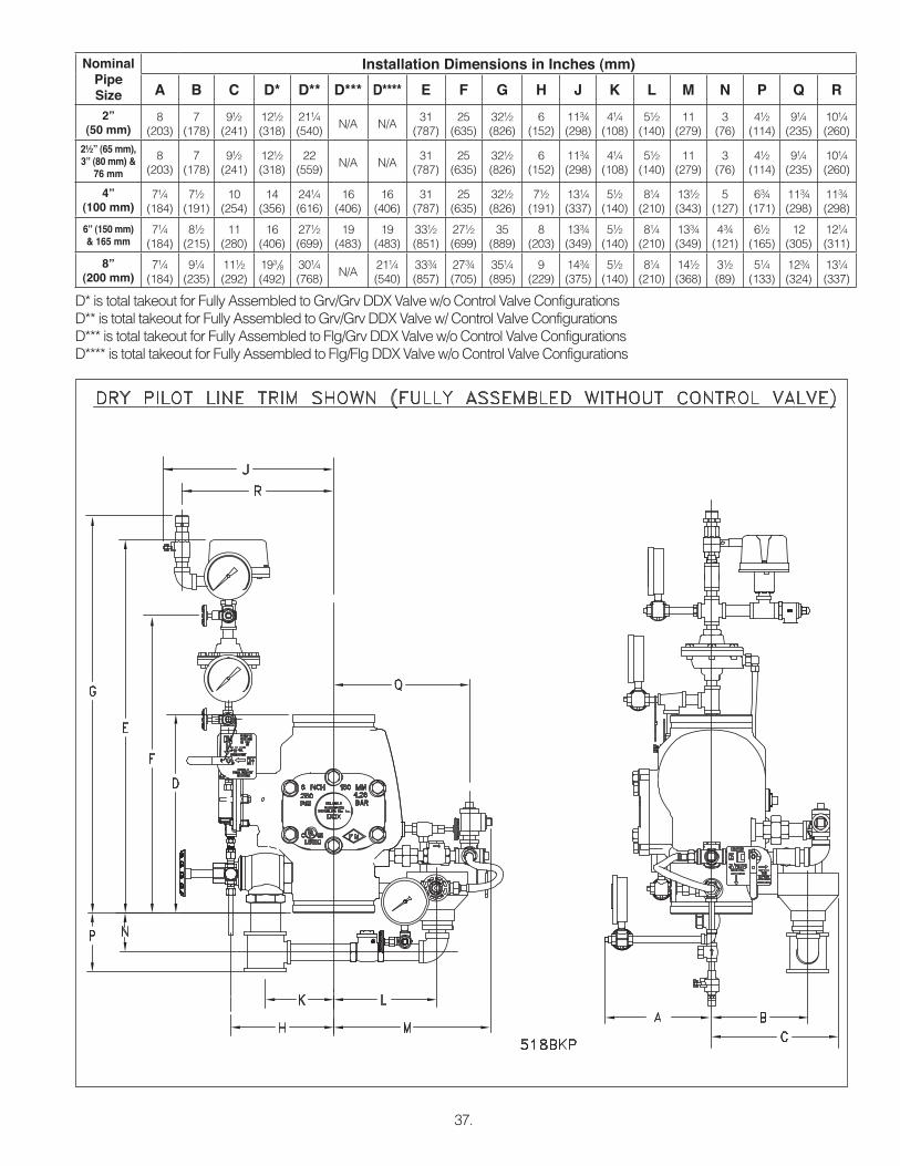
NominalPipe Size
Installation Dimensions in Inches (mm)
A B C D* D** D*** D**** E F G H J K L M N P Q R
2” (50 mm)
8 (203)
7 (178)
9½ (241)
12½ (318)
21¼ (540)
N/A N/A31
(787)25
(635)32½ (826)
6 (152)
11¾ (298)
4¼ (108)
5½ (140)
11 (279)
3 (76)
4½ (114)
9¼ (235)
10¼ (260)
2½” (65 mm), 3” (80 mm) &
76 mm
8 (203)
7 (178)
9½ (241)
12½ (318)
22 (559)
N/A N/A31
(787)25
(635)32½ (826)
6 (152)
11¾ (298)
4¼ (108)
5½ (140)
11 (279)
3 (76)
4½ (114)
9¼ (235)
10¼ (260)
4” (100 mm)
7¼ (184)
7½ (191)
10 (254)
14 (356)
24¼ (616)
16(406)
16(406)
31 (787)
25 (635)
32½ (826)
7½ (191)
13¼ (337)
5½ (140)
8¼ (210)
13½ (343)
5 (127)
6¾ (171)
11¾ (298)
11¾ (298)
6” (150 mm) & 165 mm
7¼ (184)
8½ (215)
11 (280)
16 (406)
27½ (699)
19(483)
19(483)
33½ (851)
27½ (699)
35(889)
8 (203)
13¾ (349)
5½ (140)
8¼ (210)
13¾ (349)
4¾ (121)
6½ (165)
12 (305)
12¼ (311)
8” (200 mm)
7¼ (184)
9¼ (235)
11½ (292)
193/8 (492)
30¼ (768)
N/A21¼(540)
33¾ (857)
27¾ (705)
35¼ (895)
9 (229)
14¾ (375)
5½ (140)
8¼ (210)
14½ (368)
3½ (89)
5¼ (133)
12¾ (324)
13¼ (337)
D* is total takeout for Fully Assembled to Grv/Grv DDX Valve w/o Control Valve Configurations D** is total takeout for Fully Assembled to Grv/Grv DDX Valve w/ Control Valve ConfigurationsD*** is total takeout for Fully Assembled to Flg/Grv DDX Valve w/o Control Valve ConfigurationsD**** is total takeout for Fully Assembled to Flg/Flg DDX Valve w/o Control Valve Configurations
The Reliable Automatic Sprinkler Co., Inc.(800) 431-1588 Sales Offices(800) 848-6051 Sales Fax(914) 829-2042 Corporate Officeswww.reliablesprinkler.com Internet Address
Manufactured byRecycled
Paper
Revision lines indicate updated or new data.
EG. Printed in U.S.A. 10/13 P/N 9999970439
The equipment presented in this bulletin is to be installed in accordance with the latest published Standards of the National Fire Protection Association, Factory Mutual Research Corporation, or other similar organizations and also with the provisions of governmental codes or ordinances whenever applicable.Products manufactured and distributed by Reliable have been protecting life and property for over 90 years, and are installed and serviced by the most highly qualified and reputable sprinkler contractors located throughout the United States, Canada and foreign countries.
SOLENOID VALVE INSPECTIONS, TESTS AND MAINTENANCEWARNING: THE OWNER IS RESPONSIBLE FOR MAINTAINING THE FIRE PROTECTION SYSTEM IN PROPER OPERATING CONDITION. ANY SYSTEM MAINTENANCE OR TESTING THAT INVOLVES PLACING A CON-TROL VALVE OR DETECTION SYSTEM OUT OF SERVICE MAY ELIMINATE THE FIRE PROTECTION OF THAT SYSTEM. PRIOR TO PROCEEDING, NOTIFY ALL AUTHORITIES HAVING JURISDICTION. CONSIDERATION SHOULD BE GIVEN TO EMPLOYMENT OF A FIRE PATROL IN THE AFFECTED AREA.
WARNING: PRIOR TO OPERATING THE SOLENOID VALVE, BE SURE TO CLOSE THE SYSTEM CONTROL VALVE TO AVOID UNINTENTIONAL OPERATION OF THE DELUGE VALVE
1. Inspections: It is imperative that the system be inspected and tested in accordance with NFPA 25 on a regular basis. The frequency of the inspections may vary due to contaminated water supplies, corrosive water supplies, or corrosive atmospheres. In addition, the alarm devices, detection systems, or other connected trim may require a more frequent schedule. Refer to the system description and applicable codes for minimum requirements.
2. The valve must be inspected at least monthly for cracks, corrosion, leakage, etc., and cleaned, repaired, or re-placed, or replaced as necessary.
3. If Leakage is suspected through the solenoid valve, the valve diaphragms and seat should be inspected and if necessary, repaired or replaced.
WARNING: CLOSE SYSTEM CONTROL VALVE, TURN OFF POWER SUPPLY, AND DEPRESSURIZE VALVE BEFORE DISASSEMBLING VALVE. IT IS NOT NECESSARY TO REMOVE THE VALVE FROM THE PIPE LINE TO MAKE INSPECTIONS.
4. When lubricating valve components, use high grade silicone grease (Dow Corning® 111 Compound Lubricant or equal).
5. When reassembling, tighten parts to torque values indicated in the manufacturer’s maintenance instructions (packed with valve).
6. After maintenance is completed, operate the valve a few times to be sure of proper operation. A metallic “click” signifies the solenoid is operating.
7. All service must be performed by qualified personnel. Upon completion of inspections or replacement of the valve, the entire system must be checked for proper operation. See appropriate system description and testing instruc-tions for additional information.