45
PULSAR ® Shadow MECHANICAL DIAPHRAGM METERING PUMP Bulletin: IOM-PSRM-1501 Installation, Operation & Maintenance Manual
| Date post: | 12-May-2018 |
| Category: |
Documents |
| Upload: | truongthuan |
| View: | 227 times |
| Download: | 1 times |
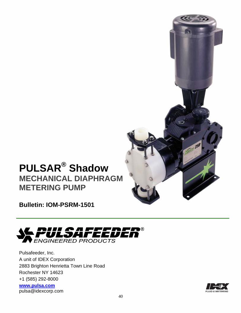
PULSAR® Shadow MECHANICAL DIAPHRAGM
METERING PUMP Bulletin: IOM-PSRM-1501
Installation, Operation & Maintenance Manual
i
PULSAR® Factory Service Policy Should you experience a problem with your PULSAR pump, first consult the troubleshooting guide in your operation and maintenance manual. If the problem is not covered or cannot be solved, please contact your local Pulsafeeder Sales Representative, or our Technical Services Department for further assistance. You may also visit our website at www.pulsa.com Trained technicians are available to diagnose your problem and arrange a solution. Solutions may include purchase of replacement parts or returning the unit to the factory for inspection and repair. All returns require a Return Authorization number to be issued by Pulsafeeder. Parts purchased to correct a warranty issue may be credited, after an examination of original parts by Pulsafeeder. Warranty parts returned as defective which test good will be sent back freight collect. No credit will be issued on any replacement electronic parts. Any modifications or out-of-warranty repairs will be subject to bench fees and costs associated with replacement parts.
Safety Considerations: 1. Read and understand all related instructions and documentation before attempting to
install or maintain this equipment
2. Observe all special instructions, notes, and cautions.
3. Act with care and exercise good common sense and judgment during all installation, adjustment, and maintenance procedures.
4. Ensure that all safety and work procedures and standards that are applicable to your company and facility are followed during the installation, maintenance, and operation of this equipment.
Notice Information and specifications in this document are subject to change without notice.
Copyright Copyright © 2003 Pulsafeeder, Inc. All rights reserved.
No part of this publication may be reproduced, stored in a retrieval system or transmitted in any form or any means electronic or mechanical, including photocopying and recording for any purpose other than the purchaser’s personal use without the written permission of Pulsafeeder, Inc.
Trademarks PULSAR® is a registered trademark of Pulsafeeder, Inc. PULSAR Shadow® is a registered trademark of Pulsafeeder, Inc. Cruise Control®, ECA®, DLC®, and DLCM® are registered trademarks of Pulsafeeder, Inc.
ii
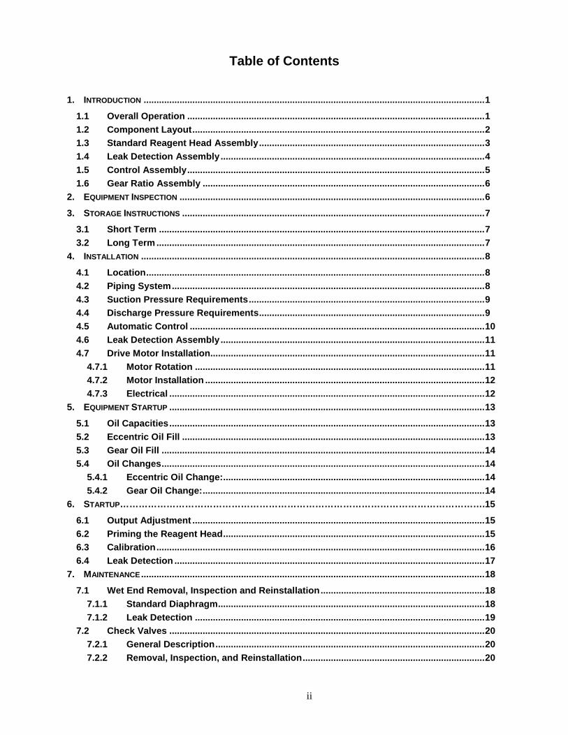
Table of Contents 1. INTRODUCTION ..................................................................................................................................... 1
1.1 Overall Operation .................................................................................................................... 1 1.2 Component Layout .................................................................................................................. 2 1.3 Standard Reagent Head Assembly ........................................................................................ 3 1.4 Leak Detection Assembly ....................................................................................................... 4 1.5 Control Assembly .................................................................................................................... 5 1.6 Gear Ratio Assembly .............................................................................................................. 6
2. EQUIPMENT INSPECTION ....................................................................................................................... 6 3. STORAGE INSTRUCTIONS ...................................................................................................................... 7
3.1 Short Term ............................................................................................................................... 7 3.2 Long Term ................................................................................................................................ 7
4. INSTALLATION ...................................................................................................................................... 8 4.1 Location .................................................................................................................................... 8 4.2 Piping System .......................................................................................................................... 8 4.3 Suction Pressure Requirements ............................................................................................ 9 4.4 Discharge Pressure Requirements ........................................................................................ 9 4.5 Automatic Control ................................................................................................................... 10 4.6 Leak Detection Assembly ....................................................................................................... 11 4.7 Drive Motor Installation........................................................................................................... 11
4.7.1 Motor Rotation ................................................................................................................. 11 4.7.2 Motor Installation ............................................................................................................. 12 4.7.3 Electrical ........................................................................................................................... 12
5. EQUIPMENT STARTUP ........................................................................................................................... 13 5.1 Oil Capacities ........................................................................................................................... 13 5.2 Eccentric Oil Fill ...................................................................................................................... 13 5.3 Gear Oil Fill .............................................................................................................................. 14 5.4 Oil Changes .............................................................................................................................. 14
5.4.1 Eccentric Oil Change: ...................................................................................................... 14 5.4.2 Gear Oil Change: .............................................................................................................. 14
6. STARTUP……………………………………………………………………………………………………….15 6.1 Output Adjustment .................................................................................................................. 15 6.2 Priming the Reagent Head ...................................................................................................... 15 6.3 Calibration ................................................................................................................................ 16 6.4 Leak Detection ......................................................................................................................... 17
7. MAINTENANCE ...................................................................................................................................... 18 7.1 Wet End Removal, Inspection and Reinstallation ................................................................ 18
7.1.1 Standard Diaphragm ........................................................................................................ 18 7.1.2 Leak Detection ................................................................................................................. 19
7.2 Check Valves ........................................................................................................................... 20 7.2.1 General Description ......................................................................................................... 20 7.2.2 Removal, Inspection, and Reinstallation ....................................................................... 20
iii
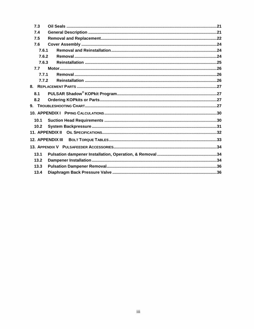
7.3 Oil Seals ................................................................................................................................... 21 7.4 General Description ................................................................................................................ 21 7.5 Removal and Replacement ..................................................................................................... 22 7.6 Cover Assembly ...................................................................................................................... 24
7.6.1 Removal and Reinstallation ............................................................................................ 24 7.6.2 Removal ............................................................................................................................ 24 7.6.3 Reinstallation ................................................................................................................... 25
7.7 Motor ......................................................................................................................................... 26 7.7.1 Removal ............................................................................................................................ 26 7.7.2 Reinstallation ................................................................................................................... 26
8. REPLACEMENT PARTS .......................................................................................................................... 27 8.1 PULSAR Shadow® KOPkit Program ....................................................................................... 27 8.2 Ordering KOPkits or Parts ...................................................................................................... 27
9. TROUBLESHOOTING CHART................................................................................................................... 27 10. APPENDIX I PIPING CALCULATIONS .................................................................................................. 30
10.1 Suction Head Requirements .................................................................................................. 30 10.2 System Backpressure ............................................................................................................. 31
11. APPENDIX II OIL SPECIFICATIONS.................................................................................................... 32 12. APPENDIX III BOLT TORQUE TABLES .............................................................................................. 33 13. APPENDIX V PULSAFEEDER ACCESSORIES .......................................................................................... 34
13.1 Pulsation dampener Installation, Operation, & Removal .................................................... 34 13.2 Dampener Installation ............................................................................................................. 34 13.3 Pulsation Dampener Removal ................................................................................................ 36 13.4 Diaphragm Back Pressure Valve ........................................................................................... 36
iv
Conventions The following Conventions are used in this document.
A WARNING DEFINES A CONDITION THAT COULD CAUSE DAMAGE TO BOTH THE EQUIPMENT AND THE PERSONNEL OPERATING IT. PAY CLOSE ATTENTION TO ANY WARNING.
NOTES ARE GENERAL INFORMATION MEANT TO MAKE OPERATING THE EQUIPMENT EASIER.
1
1. Introduction PULSAR Shadow® metering pumps are positive displacement reciprocating pumps. They combine the high efficiency of the plunger pump with diaphragm sealing to prevent product leakage. Each pump consists of a power end and a process end separated by a mechanically operated diaphragm. Individual pumps will vary in appearance due to various liquid ends, accessories, and multiplexing; however, the basic principles of operation remain the same.
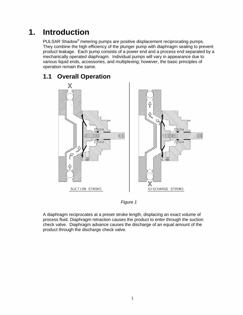
1.1 Overall Operation
Figure 1 A diaphragm reciprocates at a preset stroke length, displacing an exact volume of process fluid. Diaphragm retraction causes the product to enter through the suction check valve. Diaphragm advance causes the discharge of an equal amount of the product through the discharge check valve.
2
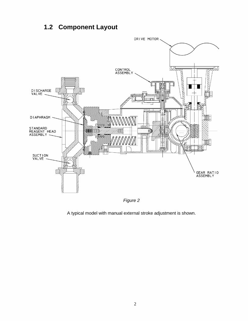
1.2 Component Layout
Figure 2
A typical model with manual external stroke adjustment is shown.
3
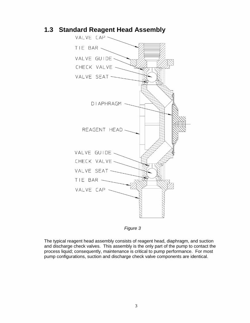
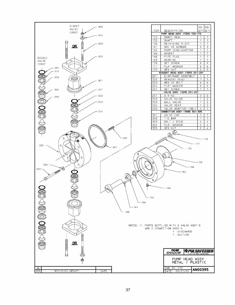
1.3 Standard Reagent Head Assembly
Figure 3 The typical reagent head assembly consists of reagent head, diaphragm, and suction and discharge check valves. This assembly is the only part of the pump to contact the process liquid; consequently, maintenance is critical to pump performance. For most pump configurations, suction and discharge check valve components are identical.
4
1.4 Leak Detection Assembly
Figure 4
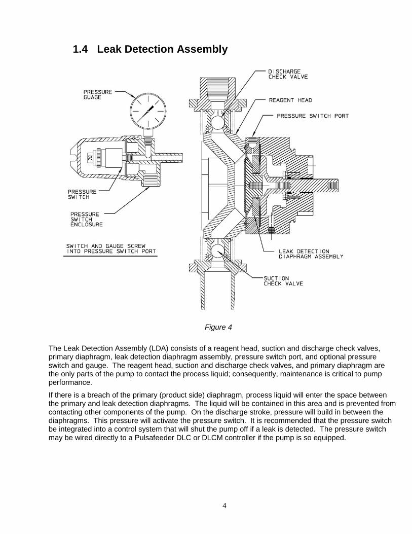
The Leak Detection Assembly (LDA) consists of a reagent head, suction and discharge check valves, primary diaphragm, leak detection diaphragm assembly, pressure switch port, and optional pressure switch and gauge. The reagent head, suction and discharge check valves, and primary diaphragm are the only parts of the pump to contact the process liquid; consequently, maintenance is critical to pump performance.
If there is a breach of the primary (product side) diaphragm, process liquid will enter the space between the primary and leak detection diaphragms. The liquid will be contained in this area and is prevented from contacting other components of the pump. On the discharge stroke, pressure will build in between the diaphragms. This pressure will activate the pressure switch. It is recommended that the pressure switch be integrated into a control system that will shut the pump off if a leak is detected. The pressure switch may be wired directly to a Pulsafeeder DLC or DLCM controller if the pump is so equipped.
5
1.5 Control Assembly
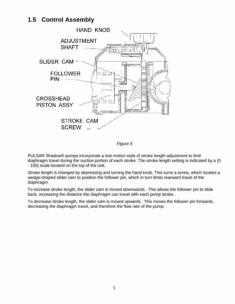
Figure 5 PULSAR Shadow® pumps incorporate a lost motion style of stroke length adjustment to limit diaphragm travel during the suction portion of each stroke. The stroke length setting is indicated by a (0 - 100) scale located on the top of the unit.
Stroke length is changed by depressing and turning the hand knob. This turns a screw, which locates a wedge-shaped slider cam to position the follower pin, which in turn limits rearward travel of the diaphragm.
To increase stroke length, the slider cam is moved downwards. This allows the follower pin to slide back, increasing the distance the diaphragm can travel with each pump stroke.
To decrease stroke length, the slider cam is moved upwards. This moves the follower pin forwards, decreasing the diaphragm travel, and therefore the flow rate of the pump.
6
1.6 Gear Ratio Assembly
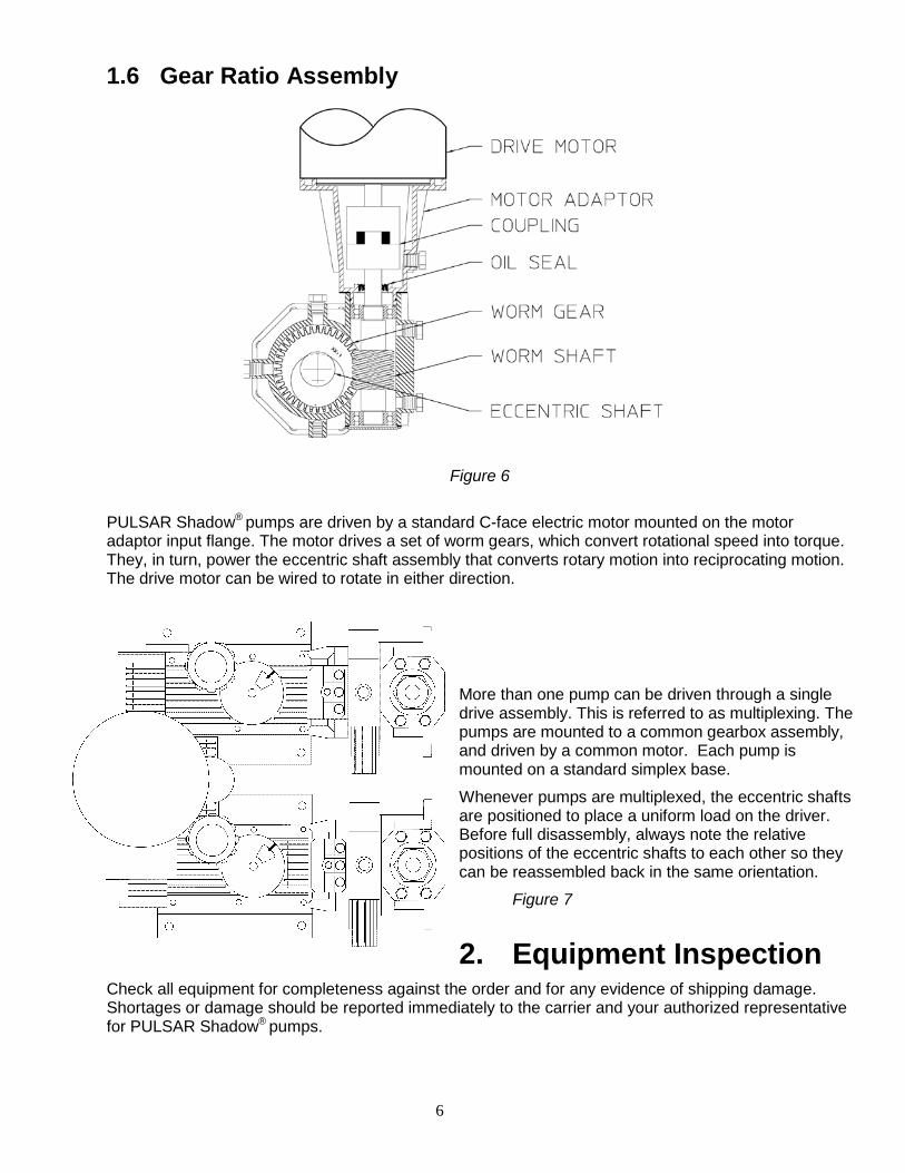
Figure 6 PULSAR Shadow® pumps are driven by a standard C-face electric motor mounted on the motor adaptor input flange. The motor drives a set of worm gears, which convert rotational speed into torque. They, in turn, power the eccentric shaft assembly that converts rotary motion into reciprocating motion. The drive motor can be wired to rotate in either direction.
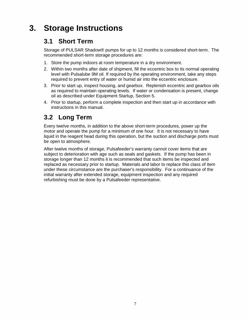
More than one pump can be driven through a single drive assembly. This is referred to as multiplexing. The pumps are mounted to a common gearbox assembly, and driven by a common motor. Each pump is mounted on a standard simplex base.
Whenever pumps are multiplexed, the eccentric shafts are positioned to place a uniform load on the driver. Before full disassembly, always note the relative positions of the eccentric shafts to each other so they can be reassembled back in the same orientation.
Figure 7
2. Equipment Inspection Check all equipment for completeness against the order and for any evidence of shipping damage. Shortages or damage should be reported immediately to the carrier and your authorized representative for PULSAR Shadow® pumps.
7
3. Storage Instructions 3.1 Short Term Storage of PULSAR Shadow® pumps for up to 12 months is considered short-term. The recommended short-term storage procedures are:
1. Store the pump indoors at room temperature in a dry environment. 2. Within two months after date of shipment, fill the eccentric box to its normal operating
level with Pulsalube 9M oil. If required by the operating environment, take any steps required to prevent entry of water or humid air into the eccentric enclosure.
3. Prior to start up, inspect housing, and gearbox. Replenish eccentric and gearbox oils as required to maintain operating levels. If water or condensation is present, change oil as described under Equipment Startup, Section 5.
4. Prior to startup, perform a complete inspection and then start up in accordance with instructions in this manual.
3.2 Long Term Every twelve months, in addition to the above short-term procedures, power up the motor and operate the pump for a minimum of one hour. It is not necessary to have liquid in the reagent head during this operation, but the suction and discharge ports must be open to atmosphere.
After twelve months of storage, Pulsafeeder’s warranty cannot cover items that are subject to deterioration with age such as seals and gaskets. If the pump has been in storage longer than 12 months it is recommended that such items be inspected and replaced as necessary prior to startup. Materials and labor to replace this class of item under these circumstance are the purchaser’s responsibility. For a continuance of the initial warranty after extended storage, equipment inspection and any required refurbishing must be done by a Pulsafeeder representative.
8
4. Installation 4.1 Location When selecting an installation site or designing a skid package, consideration should be given to access for routine maintenance.
PULSAR Shadow® pumps are designed to operate indoors and outdoors, but it is desirable to provide a hood or covering for outdoor service. External heating is required if ambient temperatures below 0O C (32O F) are anticipated. Check with the factory if concerned with the suitability of the operating environment.
The pump must be rigidly bolted to a solid and flat foundation to minimize vibration, which can loosen connections. When the pump is bolted down, care must be taken to avoid distorting the base and affecting alignments. The pump must be level within 5O. This will assure that the eccentric and gear oils are maintained at the proper levels and that the check valves can operate properly.
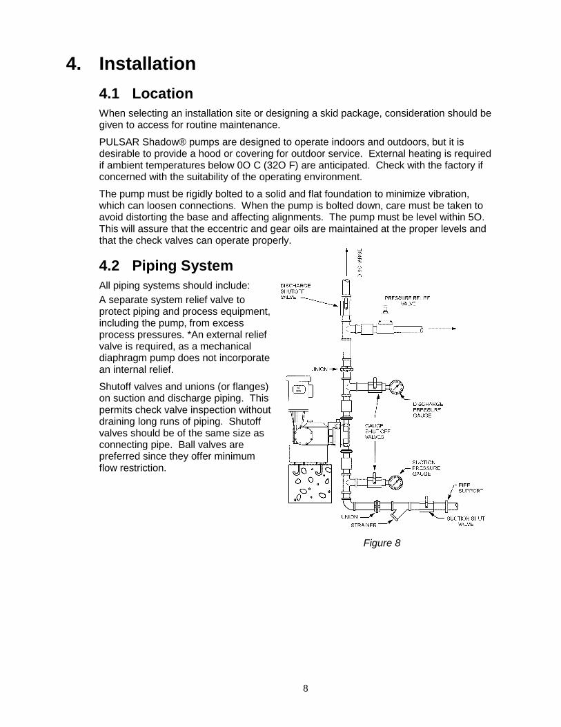
4.2 Piping System All piping systems should include: A separate system relief valve to protect piping and process equipment, including the pump, from excess process pressures. *An external relief valve is required, as a mechanical diaphragm pump does not incorporate an internal relief.
Shutoff valves and unions (or flanges) on suction and discharge piping. This permits check valve inspection without draining long runs of piping. Shutoff valves should be of the same size as connecting pipe. Ball valves are preferred since they offer minimum flow restriction.
Figure 8
9
An inlet strainer, if the product is not a slurry. Pump check valves are susceptible to dirt and other solid contaminants unless designed for that service, and any accumulation can cause malfunction. The strainer should be located between the suction shutoff valve and the pump suction valve. It must be sized to accommodate the flow rate and the anticipated level of contamination. A 100-mesh screen size is recommended.
Vacuum/pressure gauges in the suction and discharge lines in order to check system operation. Gauges should be fitted with protective shutoff valves for isolation while not in use.
Piping weight must not be supported by valve housings or other portions of the reagent head, as the resulting stresses can cause leaks. If appropriate, provide for thermal expansion and contraction so that no excess force or moments are applied to the pump.
In piping assembly, use a sealing compound chemically compatible with the process material. Users of sealing tape are cautioned to ensure that the entering pipe thread ends are not taped, and that tape is removed from previously-used threads to the maximum practical extent prior to re-use. Both new and existing piping should be cleaned, preferably by flushing with a clean liquid (compatible with process material) and blown out with air, prior to connection to the pump.
4.3 Suction Pressure Requirements Although PULSAR Shadow® metering pumps have suction lift capability, a flooded suction (i.e., suction pressure higher than atmospheric pressure) is preferable whenever possible. The pump should be located as close as possible to the suction side reservoir or other source.
For fluid with a vapor pressure of 5 psia or less (at operating temperature) the wet suction lift capability is ten (10) feet. If this requirement is not met, the pump will not provide reliable, accurate flow. The Net Positive Suction Head Required (NPSHR) is 0.35 bar (5 psi).
The maximum inlet pressure is limited to 0.35 bar (5 psi) below the operating discharge pressure.
Refer to Appendix I for procedures for the calculation of suction pressure.
4.4 Discharge Pressure Requirements All PULSAR Shadow® Metering Pumps are designed for continuous service at the rated discharge pressure. If system suction pressure were to exceed system discharge pressure (a condition sometimes described as “pumping downhill”), flow would be generated (siphoning) in addition to that caused by the pump, resulting in a reduction in accuracy and loss of control over the metering process. To prevent this condition, commonly referred to as “flowthrough”, the discharge pressure must exceed suction pressure by at least 0.35 Bar (or 5 psi). This can be achieved where necessary by the installation of a backpressure valve in the discharge line.
Damage to the pump will occur if operated at pressures beyond the maximum rating.
Refer to Appendix I for procedures for the calculation of discharge pressure.
10
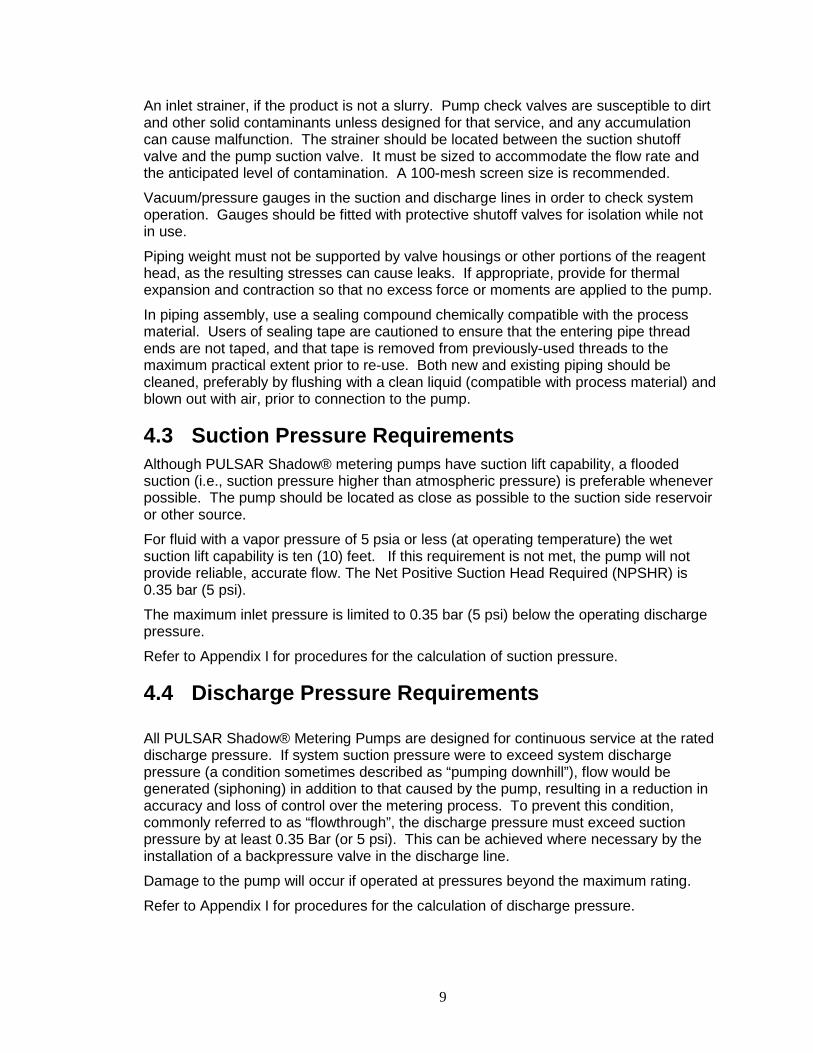
4.5 Automatic Control Pumps equipped with the DLC, DLCM, or ECA electronic stroke length controllers are provided with separate instructions. Refer to the latest Installation, Operation and Maintenance Manual specific to your controller. Follow all safety and operational information contained in those documents. Perform and verify all controller installation procedures prior to pump startup.
Figure 9
11
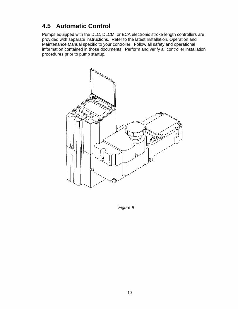
4.6 Leak Detection Assembly
Figure 10
If the diaphragm leak detection system was specified with an optional pressure switch, install electrical wiring and conduit in accordance with local electrical codes. The switch is rated as follows:
The switch is rated as follows:
30 VDC or 125 VAC 1 Ampere Resistive. The switch should be wired such that if a leak condition is detected, the pump will be shut down. The switch is the SPDT (single pole, double throw) type and can therefore be connected to either open or to close upon detection of diaphragm leak condition. Contacts or wires are identified as follows:
Normally Open (NO) wire color WHITE Normally Closed (NC) wire color RED Common (Com) wire color BLACK
THE ENCLOSURE IS LABELED WITH APPLICABLE SAFETY AGENCY RATINGS FOR HAZARDOUS AREA INSTALLATION. SINCE THE SWITCH IS OF THE MECHANICAL CONTACT TYPE, IT CAN NEVER QUALIFY AS NON-SPARKING (NON-INCENDIVE, OR “M”) FOR OCCASIONAL AND SHORT-TERM HAZARDOUS AREA USE. PROTECTION MUST BE PROVIDED BY THE ENCLOSURE.
4.7 Drive Motor Installation
4.7.1 Motor Rotation Motor can be operated in either direction, clockwise or counterclockwise. Verification of motor direction is not necessary at startup.

12
4.7.2 Motor Installation PULSAR Shadow® pumps may be shipped with the drive motor packed separately. This is done to avoid damage during transport.
Figure 11
Remove the unattached coupling half from the motor adaptor. Ensure that the elastomer coupling spider remains in place, on the coupling half that remains attached to the worm shaft.
If applicable, remove any tape or retainer rings that hold the motor shaft key in place.
Place the loose coupling half on the motor shaft. Align the keyway with the key and align shaft end to inner coupling surface as shown in figure above.
Tighten the setscrew onto the shaft key.
Place the motor in a vertical position and align the coupling teeth.
Install the motor downwards onto the adaptor. The plastic guide will assist in aligning the coupling halves. Final position can be achieved by slightly rotating the motor until the coupling jaws align.
Rotate the motor until the clearance holes in the adaptor and the tapped holes in the motor align. Fasten the motor to the adaptor using the supplied bolts (4). Tighten bolts evenly to secure motor.
4.7.3 Electrical Wire the PULSAR Shadow® drive motor according to the motor vendor’s nameplates and instructions, and according to any appropriate national and local electrical codes and regulations.
If the motor is to be utilized with a Pulsafeeder controller, such as the DLC or DLCM, consult the appropriate Pulsafeeder IOM for further motor wiring instructions.
13
5. Equipment Startup PULSAR SHADOW® PUMP USE TWO SEPARATE OILS: PULSALUBE 9M OIL FOR THE ECCENTRIC BOX AND PULSALUBE 8G, GEAR OIL FOR THE GEARBOX. CONFUSION BETWEEN THE TWO REDUCES PERFORMANCE OF THE PUMP.
5.1 Oil Capacities Pulsalube 9M lubricating oil is available in 950 ml (1 quart) containers.
Pulsalube 8G gear oil is available in 200 ml (.21 quarts) or 950 ml (1 quart) containers.
It is recommended that adequate supplies of both PULSAlube oils be on hand for periodic changes and emergency requirements. The approximate amounts of oil required to fill PULSAR Shadow® pumps to specified levels are:
Eccentric Box, all Gearbox, Model 25B Gearbox, Model 55B
Eccentric Oil, No. 9M 950 ml (1 Qt) -- --
Gear Oil, No. 8G -- 150 ml (0.16 Qt) 200 ml (0.21 Qt)
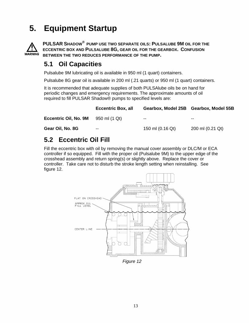
5.2 Eccentric Oil Fill Fill the eccentric box with oil by removing the manual cover assembly or DLC/M or ECA controller if so equipped. Fill with the proper oil (Pulsalube 9M) to the upper edge of the crosshead assembly and return spring(s) or slightly above. Replace the cover or controller. Take care not to disturb the stroke length setting when reinstalling. See figure 12.
Figure 12
14
5.3 Gear Oil Fill In all pump configurations, one pipe plug is present at the top of the gearbox and one is on the side at the centerline level. Remove the top plug and fill with Pulsalube 8G gear oil through the top port to the level of the eccentric shaft centerline, which is level with the side port. The side plug should be removed so that leakage from the side port indicates attainment of the required level. Replace both pipe plugs after filling. GEAR OIL IS FILLED AT THE FACTORY, AND THE GEARBOX IS SHIPPED FULL. DO NOT ADD OIL THROUGH THE PORT ON THE SIDE OF THE MOTOR ADAPTOR. THIS PORT IS FOR MOTOR COUPLING ACCESS ONLY.
5.4 Oil Changes The recommended oil change intervals are dependent upon the operating environment and level of pump usage, classified as follows:
Normal service: Clean/dry atmosphere, an ambient operating temperature of 00˚C to 400˚C (320˚F to 1040˚F) and up to 2,000 annual operating hours.
Severe Service: Humid atmosphere, an ambient operating temperature below 00˚C (320˚F) or above 400˚C (1040˚F), and over 2,000 annual operating hours.
5.4.1 Eccentric Oil Change: The recommended eccentric oil change interval is two (2) years for normal service and one (1) year for severe service. The procedure is as follows:
1. Disconnect the power source to the drive motor 2. Relieve all pressure from the piping system. 3. Remove the top cover or controller from the pump. 4. Drain the oil by removing the drain plug on the bottom of the eccentric box. 5. Replace the drain plug. 6. Fill the eccentric box with Pulsalube 9M oil as described under Eccentric Oil Fill. 7. Replace the top cover or controller.
5.4.2 Gear Oil Change: The recommended gear oil change interval is five (5) years for normal service and two (2) years for severe service. The procedure is as follows:
1. Disconnect the power source to the drive motor 2. Relieve all pressure from the piping system. 3. Remove the fill plug from the top of the gearbox. 4. Drain the oil by removing the drain plug on the bottom of the gearbox. 5. Replace the drain plug. 6. Refill with fresh Pulsalube 8G (amber) gear oil as described under Gear Oil Fill. 7. Be sure to replace the top fill plug and side plug.
15
6. Startup 6.1 Output Adjustment
Figure 13
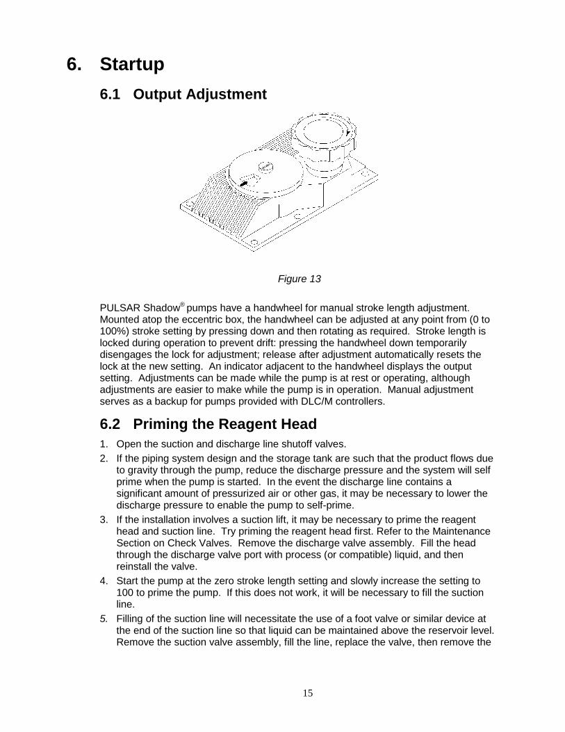
PULSAR Shadow® pumps have a handwheel for manual stroke length adjustment. Mounted atop the eccentric box, the handwheel can be adjusted at any point from (0 to 100%) stroke setting by pressing down and then rotating as required. Stroke length is locked during operation to prevent drift: pressing the handwheel down temporarily disengages the lock for adjustment; release after adjustment automatically resets the lock at the new setting. An indicator adjacent to the handwheel displays the output setting. Adjustments can be made while the pump is at rest or operating, although adjustments are easier to make while the pump is in operation. Manual adjustment serves as a backup for pumps provided with DLC/M controllers.
6.2 Priming the Reagent Head 1. Open the suction and discharge line shutoff valves. 2. If the piping system design and the storage tank are such that the product flows due
to gravity through the pump, reduce the discharge pressure and the system will self prime when the pump is started. In the event the discharge line contains a significant amount of pressurized air or other gas, it may be necessary to lower the discharge pressure to enable the pump to self-prime.
3. If the installation involves a suction lift, it may be necessary to prime the reagent head and suction line. Try priming the reagent head first. Refer to the Maintenance Section on Check Valves. Remove the discharge valve assembly. Fill the head through the discharge valve port with process (or compatible) liquid, and then reinstall the valve.
4. Start the pump at the zero stroke length setting and slowly increase the setting to 100 to prime the pump. If this does not work, it will be necessary to fill the suction line.
5. Filling of the suction line will necessitate the use of a foot valve or similar device at the end of the suction line so that liquid can be maintained above the reservoir level. Remove the suction valve assembly, fill the line, replace the valve, then remove the
16
discharge valve assembly and fill the reagent head as described in Step (3) above. The pump will now self-prime when started up per step (4) above.
6.3 Calibration
Figure 14
All metering pumps must be calibrated in order to accurately specify stroke length settings for required flow rates. For pumps provided with DLC/M electronic controls, refer to separate instructions provided with those controllers.
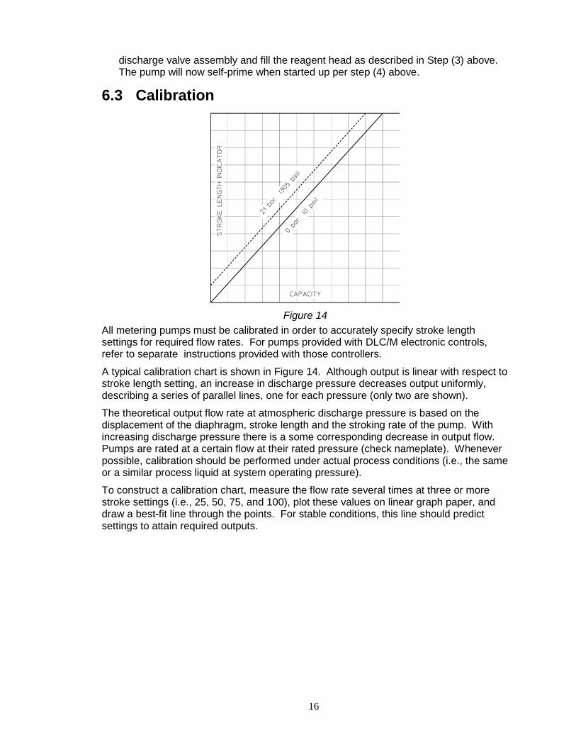
A typical calibration chart is shown in Figure 14. Although output is linear with respect to stroke length setting, an increase in discharge pressure decreases output uniformly, describing a series of parallel lines, one for each pressure (only two are shown).
The theoretical output flow rate at atmospheric discharge pressure is based on the displacement of the diaphragm, stroke length and the stroking rate of the pump. With increasing discharge pressure there is a some corresponding decrease in output flow. Pumps are rated at a certain flow at their rated pressure (check nameplate). Whenever possible, calibration should be performed under actual process conditions (i.e., the same or a similar process liquid at system operating pressure).
To construct a calibration chart, measure the flow rate several times at three or more stroke settings (i.e., 25, 50, 75, and 100), plot these values on linear graph paper, and draw a best-fit line through the points. For stable conditions, this line should predict settings to attain required outputs.
17
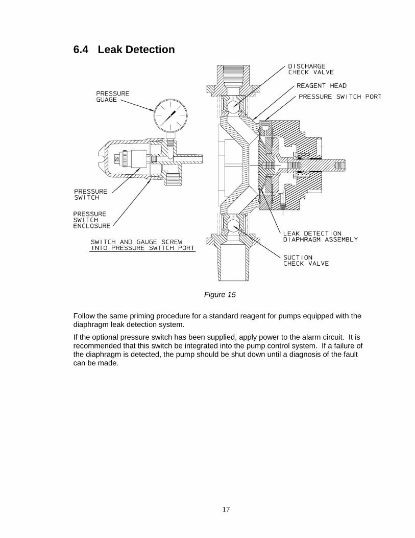
6.4 Leak Detection
Figure 15
Follow the same priming procedure for a standard reagent for pumps equipped with the diaphragm leak detection system.
If the optional pressure switch has been supplied, apply power to the alarm circuit. It is recommended that this switch be integrated into the pump control system. If a failure of the diaphragm is detected, the pump should be shut down until a diagnosis of the fault can be made.
18
7. Maintenance BEFORE PERFORMING ANY MAINTENANCE REQUIRING REAGENT HEAD OR VALVE (WET END) DISASSEMBLY, BE SURE TO RELIEVE PRESSURE FROM THE PIPING SYSTEM AND, WHERE HAZARDOUS PROCESS MATERIALS ARE INVOLVED, RENDER THE PUMP SAFE TO PERSONNEL AND THE ENVIRONMENT BY CLEANING AND CHEMICALLY NEUTRALIZING AS APPROPRIATE. WEAR PROTECTIVE CLOTHING AND EQUIPMENT AS REQUIRED. Accurate records from the early stages of pump operation will indicate the type and levels of required maintenance. A preventative maintenance program based on such records will minimize operational problems. It is not possible to forecast the lives of wetted parts such as diaphragms and check valves. Since corrosion rates and operational conditions affect functional material life, each metering pump must be considered according to its particular service conditions.
PULSAR Shadow® KOPkits contain all replacement parts normally used in a preventative maintenance program. It is recommended that KOPkits and PULSAlube eccentric and gear oils be kept available at all times.
7.1 Wet End Removal, Inspection and Reinstallation IF THE DIAPHRAGM HAS FAILED, PROCESS FLUID MAY HAVE CONTAMINATED THE PUMP ECCENTRIC OIL (ALTHOUGH NORMALLY, ANY PROCESS FLUID BEHIND A FAILED DIAPHRAGM WOULD PASS THROUGH THE BOTTOM DRAIN HOLE). HANDLE WITH APPROPRIATE CARE, CLEAN AND REPLACE OIL IF REQUIRED.
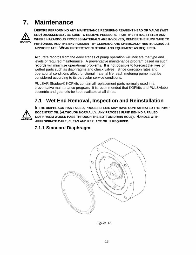
7.1.1 Standard Diaphragm
Figure 16
19
PULSAR Shadow® diaphragms do not have a specific cycle life; however, the accumulation of foreign material or debris sufficient to deform the diaphragm can eventually cause failure. Failure can also occur as a result of system over pressure or chemical attack. Periodic diaphragm inspection and replacement are recommended.
1. Adjust the stroke setting to 50 percent and disconnect the power source to the drive motor
2. Relieve all pressure from the piping system. 3. Take all precautions described in this manual to prevent environmental and
personnel exposure to hazardous materials. 4. Close the inlet and outlet shutoff valves. 5. Disconnect piping to the reagent head and drain any process liquid, following
material safety precautions described. Removal of the check valves may assist in this process.
6. Place a pan underneath the pump head adaptor to catch any liquid leakage. 7. Remove all but one top reagent head bolt. Product will leak out between the pump
head adaptor and reagent head as the bolts are loosened. 8. Tilt the head and pour out any liquids retained into a suitable container, continuing to
follow safety precautions as appropriate. 9. Remove the final bolt and rinse or clean the reagent head as required. 10. Remove the diaphragm by turning counter-clockwise and inspect the diaphragm.
The diaphragm must be replaced if any surface is cracked, separated, or obviously damaged.
11. To install a diaphragm, first ensure that the critical sealing areas of diaphragm, reagent head, and pump head are clean and free of debris. Lubricate the elastomer (back) side of the diaphragm liberally, where it is in contact against the pump head and deflection plate, with a lubricant compatible to the fluid being pumped (silicone grease is preferred ex. Parker ‘Super O-Lube’).
12. Thread the diaphragm (clockwise) fully onto the shaft. When reinstalling a used diaphragm it is not necessary to maintain the previous orientation relative to the reagent head or pump head hole pattern.
13. Install the reagent head and tighten the bolts in an alternating pattern to ensure an even seating force. Torque to the values recommended in Appendix III.
14. Replace the check valve assemblies. It is recommended that new o-ring seals be utilized when these components have been disassembled for maintenance.
15. Reprime the pump per the procedure outlined in Section 6.2
7.1.2 Leak Detection Follow the same procedures as described for the standard diaphragm, steps 1-15. IT IS NOT NECESSARY TO REMOVE OR REPLACE THE LDA SECONDARY (REAR) DIAPHRAGM UNLESS IT HAS BEEN DAMAGED.
IF DISASSEMBLY OF THE HEAD IS REQUIRED, EXERCISE CAUTION DURING REMOVAL SINCE THE RETURN SPRING OF THE PISTON IS UNDER FULL LOAD. CONSULT FACTORY PRIOR TO PERFORMING THIS PROCEDURE.
20
7.2 Check Valves
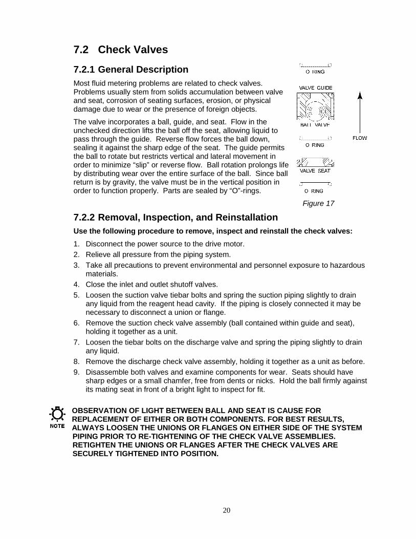
7.2.1 General Description Most fluid metering problems are related to check valves. Problems usually stem from solids accumulation between valve and seat, corrosion of seating surfaces, erosion, or physical damage due to wear or the presence of foreign objects.
The valve incorporates a ball, guide, and seat. Flow in the unchecked direction lifts the ball off the seat, allowing liquid to pass through the guide. Reverse flow forces the ball down, sealing it against the sharp edge of the seat. The guide permits the ball to rotate but restricts vertical and lateral movement in order to minimize “slip” or reverse flow. Ball rotation prolongs life by distributing wear over the entire surface of the ball. Since ball return is by gravity, the valve must be in the vertical position in order to function properly. Parts are sealed by “O”-rings.
Figure 17
7.2.2 Removal, Inspection, and Reinstallation Use the following procedure to remove, inspect and reinstall the check valves: 1. Disconnect the power source to the drive motor. 2. Relieve all pressure from the piping system. 3. Take all precautions to prevent environmental and personnel exposure to hazardous
materials. 4. Close the inlet and outlet shutoff valves. 5. Loosen the suction valve tiebar bolts and spring the suction piping slightly to drain
any liquid from the reagent head cavity. If the piping is closely connected it may be necessary to disconnect a union or flange.
6. Remove the suction check valve assembly (ball contained within guide and seat), holding it together as a unit.
7. Loosen the tiebar bolts on the discharge valve and spring the piping slightly to drain any liquid.
8. Remove the discharge check valve assembly, holding it together as a unit as before. 9. Disassemble both valves and examine components for wear. Seats should have
sharp edges or a small chamfer, free from dents or nicks. Hold the ball firmly against its mating seat in front of a bright light to inspect for fit.
OBSERVATION OF LIGHT BETWEEN BALL AND SEAT IS CAUSE FOR REPLACEMENT OF EITHER OR BOTH COMPONENTS. FOR BEST RESULTS, ALWAYS LOOSEN THE UNIONS OR FLANGES ON EITHER SIDE OF THE SYSTEM PIPING PRIOR TO RE-TIGHTENING OF THE CHECK VALVE ASSEMBLIES. RETIGHTEN THE UNIONS OR FLANGES AFTER THE CHECK VALVES ARE SECURELY TIGHTENED INTO POSITION.
21
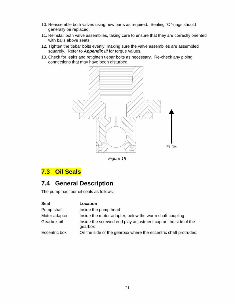
10. Reassemble both valves using new parts as required. Sealing “O”-rings should generally be replaced.
11. Reinstall both valve assemblies, taking care to ensure that they are correctly oriented with balls above seats.
12. Tighten the tiebar bolts evenly, making sure the valve assemblies are assembled squarely. Refer to Appendix III for torque values.
13. Check for leaks and retighten tiebar bolts as necessary. Re-check any piping connections that may have been disturbed.
Figure 18
7.3 Oil Seals
7.4 General Description The pump has four oil seals as follows: Seal Location Pump shaft Inside the pump head Motor adapter Inside the motor adapter, below the worm shaft coupling Gearbox oil Inside the screwed end play adjustment cap on the side of the
gearbox Eccentric box On the side of the gearbox where the eccentric shaft protrudes.
22
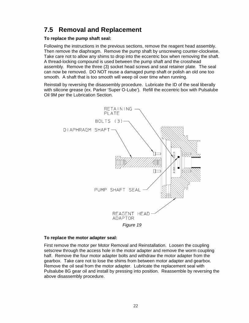
7.5 Removal and Replacement To replace the pump shaft seal: Following the instructions in the previous sections, remove the reagent head assembly. Then remove the diaphragm. Remove the pump shaft by unscrewing counter-clockwise. Take care not to allow any shims to drop into the eccentric box when removing the shaft. A thread-locking compound is used between the pump shaft and the crosshead assembly. Remove the three (3) socket head screws and seal retainer plate. The seal can now be removed. DO NOT reuse a damaged pump shaft or polish an old one too smooth. A shaft that is too smooth will weep oil over time when running.
Reinstall by reversing the disassembly procedure. Lubricate the ID of the seal liberally with silicone grease (ex. Parker ‘Super O-Lube’). Refill the eccentric box with Pulsalube Oil 9M per the Lubrication Section.
Figure 19
To replace the motor adapter seal: First remove the motor per Motor Removal and Reinstallation. Loosen the coupling setscrew through the access hole in the motor adapter and remove the worm coupling half. Remove the four motor adapter bolts and withdraw the motor adapter from the gearbox. Take care not to lose the shims from between motor adapter and gearbox. Remove the oil seal from the motor adapter. Lubricate the replacement seal with Pulsalube 8G gear oil and install by pressing into position. Reassemble by reversing the above disassembly procedure.
23
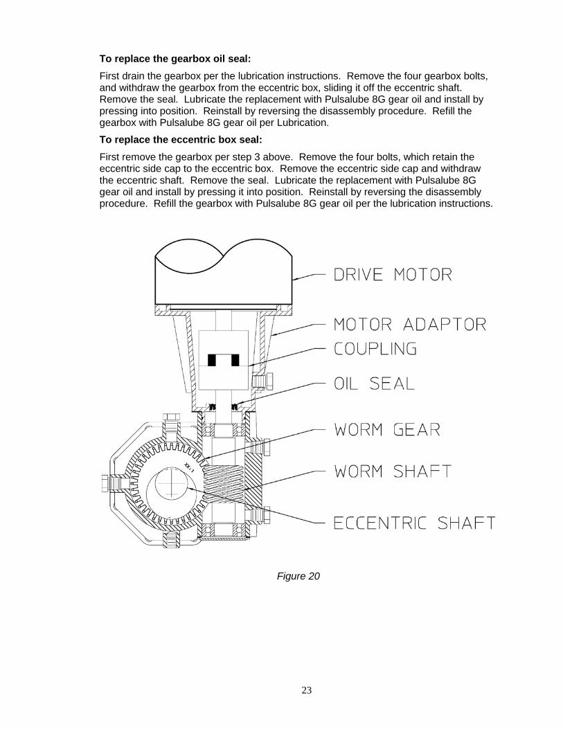
To replace the gearbox oil seal: First drain the gearbox per the lubrication instructions. Remove the four gearbox bolts, and withdraw the gearbox from the eccentric box, sliding it off the eccentric shaft. Remove the seal. Lubricate the replacement with Pulsalube 8G gear oil and install by pressing into position. Reinstall by reversing the disassembly procedure. Refill the gearbox with Pulsalube 8G gear oil per Lubrication.
To replace the eccentric box seal: First remove the gearbox per step 3 above. Remove the four bolts, which retain the eccentric side cap to the eccentric box. Remove the eccentric side cap and withdraw the eccentric shaft. Remove the seal. Lubricate the replacement with Pulsalube 8G gear oil and install by pressing it into position. Reinstall by reversing the disassembly procedure. Refill the gearbox with Pulsalube 8G gear oil per the lubrication instructions.
Figure 20
24
7.6 Cover Assembly
7.6.1 Removal and Reinstallation
Figure 21
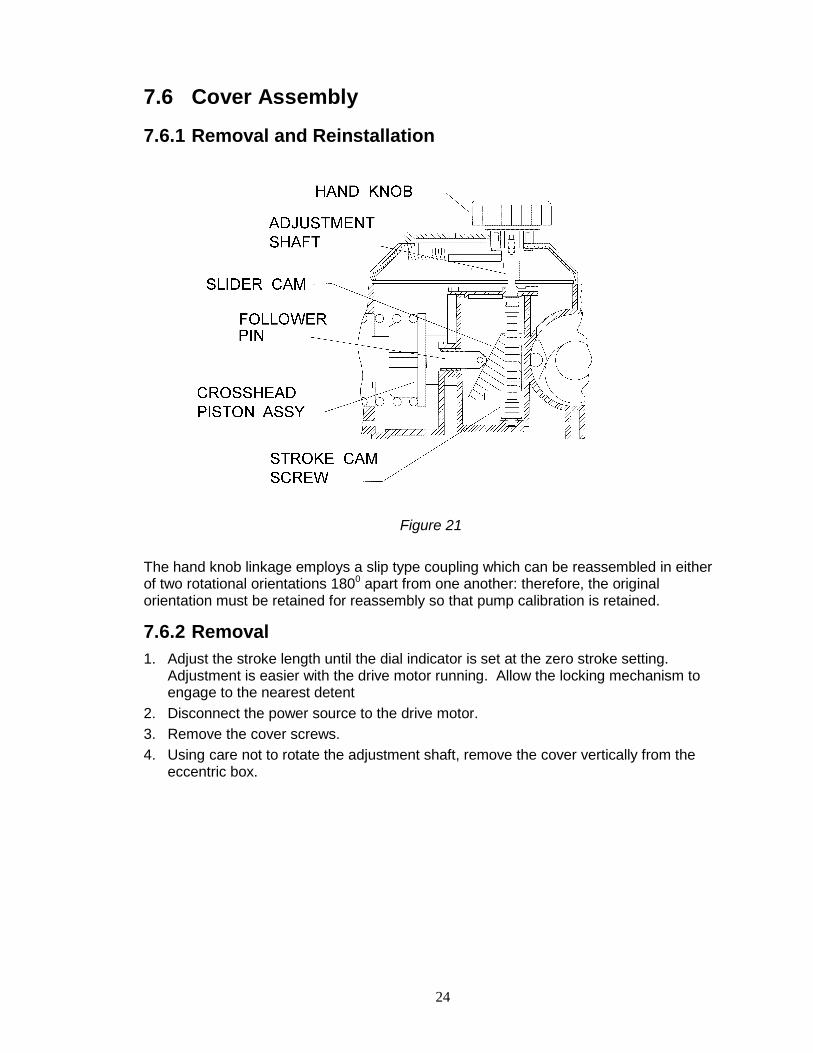
The hand knob linkage employs a slip type coupling which can be reassembled in either of two rotational orientations 1800 apart from one another: therefore, the original orientation must be retained for reassembly so that pump calibration is retained.
7.6.2 Removal 1. Adjust the stroke length until the dial indicator is set at the zero stroke setting.
Adjustment is easier with the drive motor running. Allow the locking mechanism to engage to the nearest detent
2. Disconnect the power source to the drive motor. 3. Remove the cover screws. 4. Using care not to rotate the adjustment shaft, remove the cover vertically from the
eccentric box.
25
7.6.3 Reinstallation 1. Rotate the stroke cam screw clockwise until the slider cam is in a full upward
position. 2. Verify that the cover dial indicates the zero stroke setting. 3. Using care not to disturb the adjustment shaft, install the cover assembly, engaging
the drive coupling. 4. Replace the cover screws.
26
5. Press the adjustment knob down and rotate it clockwise until it stops. (Adjustment is easier with the drive motor running.) Verify that the cover dial indicates the zero stroke setting as before; if so, reinstallation is complete and if not, refer to step (6) below for realignment.
6. To re-align, loosen the screw in the center of the dial cover. 7. Adjust the dial cover to align the pointer with the ‘zero’ mark. 8. Retighten the screw in the center of the dial cover.
7.7 Motor
7.7.1 Removal 1. Disconnect the power source to the drive motor. 2. Disconnect the motor wiring from the motor. 3. Remove the four bolts retaining the motor to the motor adaptor and remove the
motor. 4. The coupling is an interlocking jaw design and uses an elastomer spider between the
two coupling halves. One half of the coupling remains on the worm shaft and the other coupling half on the motor shaft. Loosen the setscrew, which retains the coupling half to the motor shaft and remove the coupling half, taking care to not lose the shaft key.
7.7.2 Reinstallation See instructions, Section 4.7 MOTOR ROTATION MAY BE WIRED FOR CW OR CCW ROTATION.
27
8. Replacement Parts 8.1 PULSAR Shadow® KOPkit Program
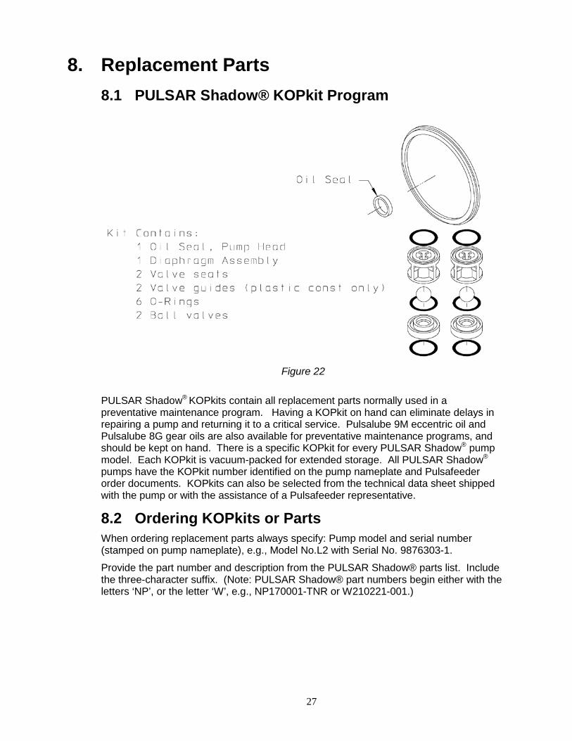
Figure 22
PULSAR Shadow® KOPkits contain all replacement parts normally used in a preventative maintenance program. Having a KOPkit on hand can eliminate delays in repairing a pump and returning it to a critical service. Pulsalube 9M eccentric oil and Pulsalube 8G gear oils are also available for preventative maintenance programs, and should be kept on hand. There is a specific KOPkit for every PULSAR Shadow® pump model. Each KOPkit is vacuum-packed for extended storage. All PULSAR Shadow®
pumps have the KOPkit number identified on the pump nameplate and Pulsafeeder order documents. KOPkits can also be selected from the technical data sheet shipped with the pump or with the assistance of a Pulsafeeder representative.
8.2 Ordering KOPkits or Parts When ordering replacement parts always specify: Pump model and serial number (stamped on pump nameplate), e.g., Model No.L2 with Serial No. 9876303-1.
Provide the part number and description from the PULSAR Shadow® parts list. Include the three-character suffix. (Note: PULSAR Shadow® part numbers begin either with the letters ‘NP’, or the letter ‘W’, e.g., NP170001-TNR or W210221-001.)
28
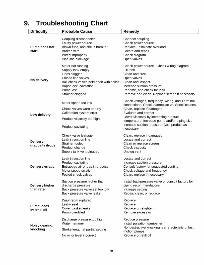
9. Troubleshooting Chart Difficulty Probable Cause Remedy
Pump does not start
Coupling disconnected Connect coupling Faulty power source Check power source Blown fuse, and circuit breaker Replace - eliminate overload Broken wire Locate and repair Wired improperly Check diagram Pipe line blockage Open valves
No delivery
Motor not running Check power source. Check wiring diagram Supply tank empty Fill tank Lines clogged Clean and flush Closed line valves Open valves Ball check valves held open with solids Clean and inspect Vapor lock, cavitation Increase suction pressure Prime lost Reprime, and check for leak Strainer clogged Remove and clean. Replace screen if necessary
Low delivery
Motor speed too low Check voltages, frequency, wiring, and Terminal connections. Check nameplate vs. Specifications
Check valves worn or dirty Clean, replace if damaged Calibration system error Evaluate and correct
Product viscosity too high Lower viscosity by increasing product temperature. Increase pump and/or piping size
Product cavitating Increase suction pressure. Cool product as necessary
Delivery gradually drops
Check valve leakage Clean, replace if damaged Leak in suction line Locate and correct Strainer fouled Clean or replace screen Product change Check viscosity Supply tank vent plugged Unplug vent
Delivery erratic
Leak in suction line Locate and correct Product cavitating Increase suction pressure Entrapped air or gas in product Consult factory for suggested venting Motor speed erratic Check voltage and frequency Fouled check valves Clean, replace if necessary
Delivery higher than rated
Suction pressure higher than discharge pressure
Install backpressure valve or consult factory for piping recommendations
Back pressure valve set too low Increase setting Back pressure valve leaks Repair, clean, or replace
Pump loses internal oil
Diaphragm ruptured Replace Leaky seal Replace Cover gasket leaks Replace or retighten Pump overfilled Remove excess oil
Noisy gearing, knocking
Discharge pressure too high Reduce pressure Water hammer Install pulsation dampener
Stroke length at partial setting Nondestructive knocking is characteristic of lost motion pumps
No oil or level incorrect Replace or refill oil
29
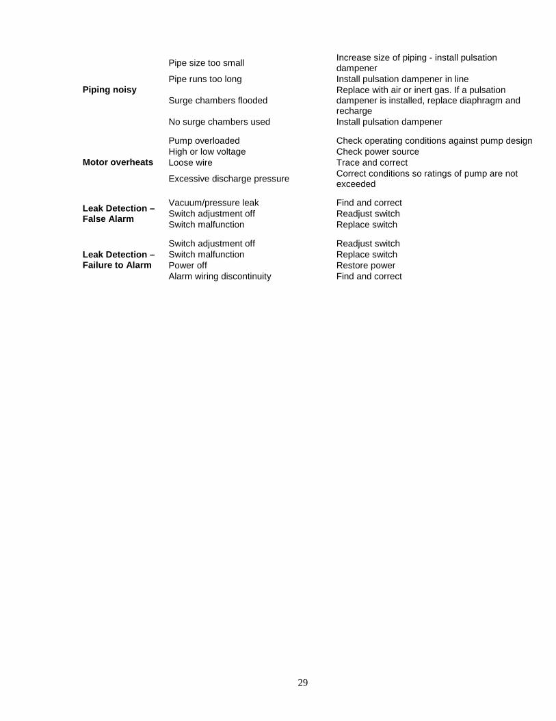
Piping noisy
Pipe size too small Increase size of piping - install pulsation dampener
Pipe runs too long Install pulsation dampener in line
Surge chambers flooded Replace with air or inert gas. If a pulsation dampener is installed, replace diaphragm and recharge
No surge chambers used Install pulsation dampener
Motor overheats
Pump overloaded Check operating conditions against pump design High or low voltage Check power source Loose wire Trace and correct
Excessive discharge pressure Correct conditions so ratings of pump are not exceeded
Leak Detection – False Alarm
Vacuum/pressure leak Find and correct Switch adjustment off Readjust switch Switch malfunction Replace switch
Leak Detection – Failure to Alarm
Switch adjustment off Readjust switch Switch malfunction Replace switch Power off Restore power Alarm wiring discontinuity Find and correct
30
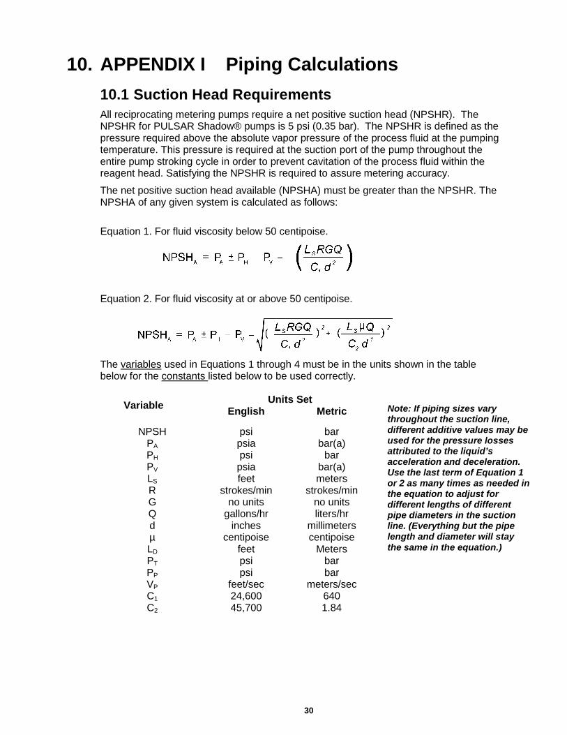
10. APPENDIX I Piping Calculations 10.1 Suction Head Requirements All reciprocating metering pumps require a net positive suction head (NPSHR). The NPSHR for PULSAR Shadow® pumps is 5 psi (0.35 bar). The NPSHR is defined as the pressure required above the absolute vapor pressure of the process fluid at the pumping temperature. This pressure is required at the suction port of the pump throughout the entire pump stroking cycle in order to prevent cavitation of the process fluid within the reagent head. Satisfying the NPSHR is required to assure metering accuracy.
The net positive suction head available (NPSHA) must be greater than the NPSHR. The NPSHA of any given system is calculated as follows:
Equation 1. For fluid viscosity below 50 centipoise.
Equation 2. For fluid viscosity at or above 50 centipoise.
The variables used in Equations 1 through 4 must be in the units shown in the table below for the constants listed below to be used correctly.
Variable Units Set English Metric
NPSH psi bar
PA psia bar(a) PH psi bar PV psia bar(a) LS feet meters R strokes/min strokes/min G no units no units Q gallons/hr liters/hr d inches millimeters µ centipoise centipoise LD feet Meters PT psi bar PP psi bar VP feet/sec meters/sec C1 24,600 640 C2 45,700 1.84
Note: If piping sizes vary throughout the suction line, different additive values may be used for the pressure losses attributed to the liquid’s acceleration and deceleration. Use the last term of Equation 1 or 2 as many times as needed in the equation to adjust for different lengths of different pipe diameters in the suction line. (Everything but the pipe length and diameter will stay the same in the equation.)
31
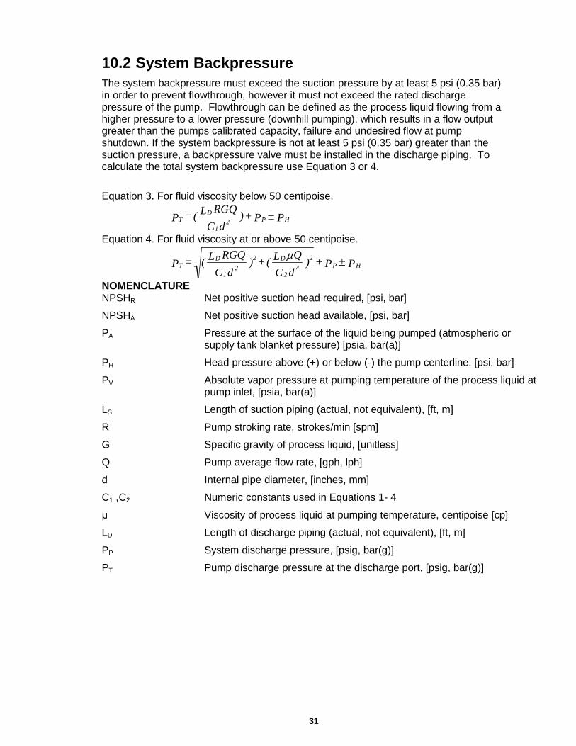
10.2 System Backpressure The system backpressure must exceed the suction pressure by at least 5 psi (0.35 bar) in order to prevent flowthrough, however it must not exceed the rated discharge pressure of the pump. Flowthrough can be defined as the process liquid flowing from a higher pressure to a lower pressure (downhill pumping), which results in a flow output greater than the pumps calibrated capacity, failure and undesired flow at pump shutdown. If the system backpressure is not at least 5 psi (0.35 bar) greater than the suction pressure, a backpressure valve must be installed in the discharge piping. To calculate the total system backpressure use Equation 3 or 4.
Equation 3. For fluid viscosity below 50 centipoise.
P P + )dC
RGQL( = P HP21
DT ±
Equation 4. For fluid viscosity at or above 50 centipoise.
P P + )dCQL(+)
dCRGQL( = P HP
24
2
D22
1
DT ±
µ
NOMENCLATURE NPSHR Net positive suction head required, [psi, bar]
NPSHA Net positive suction head available, [psi, bar]
PA Pressure at the surface of the liquid being pumped (atmospheric or supply tank blanket pressure) [psia, bar(a)]
PH Head pressure above (+) or below (-) the pump centerline, [psi, bar]
PV Absolute vapor pressure at pumping temperature of the process liquid at pump inlet, [psia, bar(a)]
LS Length of suction piping (actual, not equivalent), [ft, m]
R Pump stroking rate, strokes/min [spm]
G Specific gravity of process liquid, [unitless]
Q Pump average flow rate, [gph, lph]
d Internal pipe diameter, [inches, mm]
C1 ,C2 Numeric constants used in Equations 1- 4
μ Viscosity of process liquid at pumping temperature, centipoise [cp]
LD Length of discharge piping (actual, not equivalent), [ft, m]
PP System discharge pressure, [psig, bar(g)]
PT Pump discharge pressure at the discharge port, [psig, bar(g)]
32
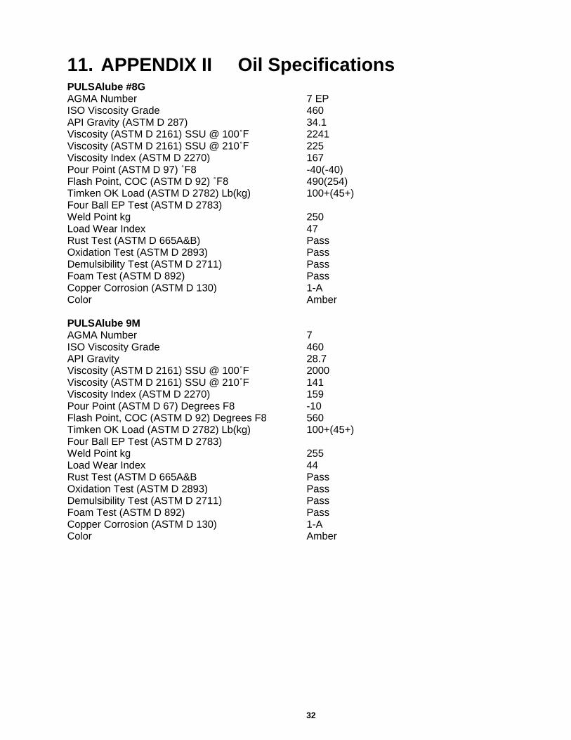
11. APPENDIX II Oil Specifications PULSAlube #8G AGMA Number 7 EP ISO Viscosity Grade 460 API Gravity (ASTM D 287) 34.1 Viscosity (ASTM D 2161) SSU @ 100˚F 2241 Viscosity (ASTM D 2161) SSU @ 210˚F 225 Viscosity Index (ASTM D 2270) 167 Pour Point (ASTM D 97) ˚F8 -40(-40) Flash Point, COC (ASTM D 92) ˚F8 490(254) Timken OK Load (ASTM D 2782) Lb(kg) 100+(45+) Four Ball EP Test (ASTM D 2783) Weld Point kg 250 Load Wear Index 47 Rust Test (ASTM D 665A&B) Pass Oxidation Test (ASTM D 2893) Pass Demulsibility Test (ASTM D 2711) Pass Foam Test (ASTM D 892) Pass Copper Corrosion (ASTM D 130) 1-A Color Amber PULSAlube 9M AGMA Number 7 ISO Viscosity Grade 460 API Gravity 28.7 Viscosity (ASTM D 2161) SSU @ 100˚F 2000 Viscosity (ASTM D 2161) SSU @ 210˚F 141 Viscosity Index (ASTM D 2270) 159 Pour Point (ASTM D 67) Degrees F8 -10 Flash Point, COC (ASTM D 92) Degrees F8 560 Timken OK Load (ASTM D 2782) Lb(kg) 100+(45+) Four Ball EP Test (ASTM D 2783) Weld Point kg 255 Load Wear Index 44 Rust Test (ASTM D 665A&B Pass Oxidation Test (ASTM D 2893) Pass Demulsibility Test (ASTM D 2711) Pass Foam Test (ASTM D 892) Pass Copper Corrosion (ASTM D 130) 1-A Color Amber
33
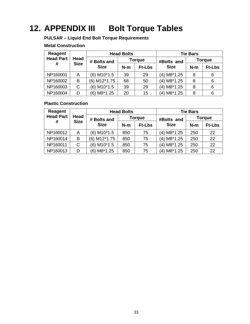
12. APPENDIX III Bolt Torque Tables PULSAR – Liquid End Bolt Torque Requirements Metal Construction
Reagent Head Part
#
Head Size
Head Bolts Tie Bars # Bolts and
Size Torque #Bolts and
Size Torque
N-m Ft-Lbs N-m Ft-Lbs NP160001 A (6) M10*1.5 39 29 (4) M8*1.25 8 6 NP160002 B (6) M12*1.75 68 50 (4) M8*1.25 8 6 NP160003 C (6) M10*1.5 39 29 (4) M8*1.25 8 6 NP160004 D (6) M8*1.25 20 15 (4) M8*1.25 8 6
Plastic Construction
Reagent Head Part
#
Head Size
Head Bolts Tie Bars # Bolts and
Size Torque #Bolts and
Size Torque
N-m Ft-Lbs N-m Ft-Lbs NP160012 A (6) M10*1.5 850 75 (4) M8*1.25 250 22 NP160014 B (6) M12*1.75 850 75 (4) M8*1.25 250 22 NP160011 C (6) M10*1.5 850 75 (4) M8*1.25 250 22 NP160013 D (6) M8*1.25 850 75 (4) M8*1.25 250 22
34
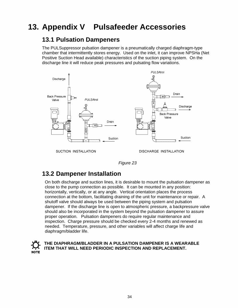
13. Appendix V Pulsafeeder Accessories 13.1 Pulsation Dampeners The PULSuppressor pulsation dampener is a pneumatically charged diaphragm-type chamber that intermittently stores energy. Used on the inlet, it can improve NPSHa (Net Positive Suction Head available) characteristics of the suction piping system. On the discharge line it will reduce peak pressures and pulsating flow variations.
Figure 23
13.2 Dampener Installation On both discharge and suction lines, it is desirable to mount the pulsation dampener as close to the pump connection as possible. It can be mounted in any position: horizontally, vertically, or at any angle. Vertical orientation places the process connection at the bottom, facilitating draining of the unit for maintenance or repair. A shutoff valve should always be used between the piping system and pulsation dampener. If the discharge line is open to atmospheric pressure, a backpressure valve should also be incorporated in the system beyond the pulsation dampener to assure proper operation. Pulsation dampeners do require regular maintenance and inspection. Charge pressure should be checked every 2-4 months and renewed as needed. Temperature, pressure, and other variables will affect charge life and diaphragm/bladder life.
THE DIAPHRAGM/BLADDER IN A PULSATION DAMPENER IS A WEARABLE ITEM THAT WILL NEED PERIODIC INSPECTION AND REPLACEMENT.
35
A) Discharge Setup The pulsation dampener may be precharged with air or nitrogen. When properly precharged the diaphragm is positioned against the bottom liquid chamber. It is therefore necessary to drain all liquid below the diaphragm and vent to atmospheric pressure when precharging.
Use the precharge pressure as determined from the pulsation dampener selection and sizing procedure (Catalog No. 211). This can vary from 50 to 80% of mean line pressure in accordance with fluctuation level selected. The pulsation dampener is now ready for service and the diaphragm will move to a neutral position as liquid enters the chamber.
Use the following to complete a Pre Charge Procedure for Discharge Installation 1. Calculate the precharge pressure
a. Mean Line Pressure (PSIG) + Atmospheric Pressure = Absolute Pressure (PSIA) b. Absolute Pressure (PSIA) x Precharge Percentage (80% max) = Pressure Absolute c. Pressure Absolute – Atmospheric Pressure = Precharge Pressure (PSIG)
2. Isolate the pulsation dampener from the process line. 3. Carefully drain off process fluid by opening a drain valve (see recommend piping
arrangement). 4. Apply precharge pressure (additional liquid may drain as diaphragm moves). 5. Close drain valve. 6. Place the pulsation dampener in the process stream.
B) Suction Setup (Flooded Suction) Charge the pulsation dampener with adequate pressure to overcome the static suction head. Start up the pump. Depress the stem on the charge valve, but only during discharge strokes of the pump, until the gauge indicates pressure pulses. The diaphragm has now centered allowing the pulsation dampener to accumulate liquid while the pump is discharging. If too much air becomes released and the gauge will not indicate pressure pulses, recharge the pulsation dampener and repeat the procedure.
Use the following to complete a Pre Charge Procedure for Suction Installation 1. Isolate accumulator from line. 2. Carefully drain off process fluid by opening a drain valve 3. Apply 5-10 psi precharge pressure (additional liquid may drain as diaphragm moves). 4. Close drain valve. 5. Bleed off all pressure on the pulsation dampener. 6. Open the valve to put pulsation dampener in stream. 7. Push in on the stem of the charging valve during the discharge stroke of the pump
and release during the suction stroke. 8. Continue this for about 10 times and observe the compound gauge. As accumulator
functions, the needle will go from pressure to vacuum.
36
13.3 Pulsation Dampener Removal When removing or disassembling a pulsation dampener, drain all piping and remove all air and process pressure. Assume that the diaphragm is broken and the chamber is flooded under pressure since the pressure gauge could be damaged. Separate chambers with caution in a direction away from the body.
REMEMBER THAT THE PULSATION DAMPENER HOUSING WILL RETAIN SOME AMOUNT OF PROCESS FLUID, AND HANDLE ACCORDINGLY.
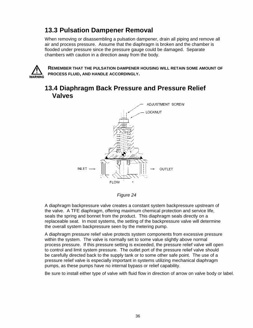
13.4 Diaphragm Back Pressure and Pressure Relief Valves
Figure 24
A diaphragm backpressure valve creates a constant system backpressure upstream of the valve. A TFE diaphragm, offering maximum chemical protection and service life, seals the spring and bonnet from the product. This diaphragm seals directly on a replaceable seat. In most systems, the setting of the backpressure valve will determine the overall system backpressure seen by the metering pump.
A diaphragm pressure relief valve protects system components from excessive pressure within the system. The valve is normally set to some value slightly above normal process pressure. If this pressure setting is exceeded, the pressure relief valve will open to control and limit system pressure. The outlet port of the pressure relief valve should be carefully directed back to the supply tank or to some other safe point. The use of a pressure relief valve is especially important in systems utilizing mechanical diaphragm pumps, as these pumps have no internal bypass or relief capability.
Be sure to install either type of valve with fluid flow in direction of arrow on valve body or label.
37

38
39
40
PULSAR® Shadow MECHANICAL DIAPHRAGM METERING PUMP Bulletin: IOM-PSRM-1501
Pulsafeeder, Inc. A unit of IDEX Corporation 2883 Brighton Henrietta Town Line Road Rochester NY 14623 +1 (585) 292-8000 www.pulsa.com [email protected]


