Heat Exchanger OptionsC = Copper coax (with e-coated air coil)N = CuNi coax (with e-coated air coil)
Blower Options1 = ECM
Discharge Air ConfigurationM = Multi-position
Return OptionsM = Multi-position
Hot Water Options0 = No Desuperheater1 = With Desuperheater & int. pump
1 2 3 4 5 6 7 8 9 10 11 12 13 14 15
3August 2010, RXT IOM Roth
Section 2: Introduction
INTRODUCTION:This geothermal heat pump provides heating and cooling as well as optional domestic water heating capability. Engineering and quality control is built into every geothermal unit. Good performance depends on proper application and correct installation.
Notices, Cautions, Warnings, & Dangers
“NOTICE” Notification of installation, operation or maintenance information which is important, but which is NOT hazard-related.
“CAUTION” Indicates a potentially hazardous situation or an unsafe practice which, if not avoided, COULD result in minor or moderate injury or product or property damage.
“WARNING” Indicates potentially hazardous situation which, if not avoided, COULD result in death or serious injury.
“DANGER” Indicates an immediate hazardous situation which, if not avoided, WILL result in death or serious injury.
Inspection:Upon receipt of any geothermal equipment, carefully check the shipment against the packing slip and the freight company bill of lading. Verify that all units and packages have been received. Inspect the packaging of each package and each unit for damages. Insure that the carrier makes proper notation of all damages or shortage on all bill of lading papers. Concealed damage should be reported to the freight company within 15 days. If not filed within 15 days the freight company can deny all claims.
Note: Notify Roth shipping department of all damages within 15 days. It is the responsibility of the purchaser to file all necessary claims with the freight company.
Unit Protection:Protect units from damage and contamination due to plastering (spraying), painting and all other foreign materials that may be used at the job site. Keep all units covered on the job site with either the original packaging or
equivalent protective covering. Cap or recap unit connections and all piping until unit is installed. Precautions must be taken to avoid physical damage and contamination which may prevent proper start-up and may result in costly equipment repair.
⚠ CAUTION ⚠DO NOT OPERATE THE GEOTHERMAL HEAT PUMP UNIT DURING BUILDING
CONSTRUCTION PHASE.
Storage:All geothermal units should be stored inside in the original packaging in a clean, dry location. Units should be stored in an upright position at all times. Units should not be stacked unless specially noted on the packaging.
Pre-Installation:Special care should be taken in locating the geothermal unit. Installation location chosen should include adequate service clearance around the unit. All vertical units should be placed on a vibration-absorbing pad (air pad) slightly larger than the base of the unit. Flex connectors should also be installed in between the ductwork and the unit. All units should be located in an indoor area where the ambient temperature will remain above 55°F and should be located in a way that piping and ductwork or other permanently installed fixtures do not have to be removed for servicing and filter replacement.
Pre-Installation Steps:
1. Compare the electrical data on the unit nameplate with packing slip and ordering information to verify that the correct unit has been shipped.
2. Remove any packaging used to support blower during shipping.
3. Inspect all electrical connectionsand wires. Connections must be clean and tight at the terminals, and wires should not touch any sharp edges or copper pipe.
4Roth RXT IOM, August 2010
4. Verify that all refrigerant tubing is free of dents and kinks. Refrigerant tubing should not be touching other unit components.
5. Before unit start-up, read all manuals and become familiar with unit components and operation. Thoroughly check the unit before operating.
⚠ CAUTION ⚠ALL GEOTHERMAL EqUIPMENT IS
DESIGNED FOR INDOOR INSTALLATION ONLy. DO NOT INSTALL OR STORE UNIT IN A CORROSIvE ENvIRONMENT OR IN A LOCATION WHERE TEMPERATURE AND HUMIDITy ARE SUBjECT TO EXTREMES.
EqUIPMENT IS NOT CERTIFIED FOR OUTDOOR APPLICATIONS. SUCH
INSTALLATION WILL vOID ALL WARRANTIES.
⚠ WARNING ⚠FAILURE TO FOLLOW THIS CAUTION MAy RESULT IN PERSONAL INjURy. USE CARE AND WEAR APPROPRIATE PROTECTIvE
CLOTHING, SAFETy GLASSES AND PROTECTIvE GLOvES WHEN SERvICING
UNIT AND HANDLING PARTS.
⚠ CAUTION ⚠BEFORE DRILLING OR DRIvING ANy
SCREWS INTO CABINET, CHECk TO BE SURE THE SCREW WILL NOT HIT ANy
Logic Board: Logic Board operates the compressor and protects unit by locking out when safety switches are engaged. It also provides fault indicator(s).
Terminal Strip: Provides connection to the thermostat or other accessories to the low voltage circuit.
Transformer: Converts incoming (source) voltage to 24V AC.
Low Voltage Breaker: Attached directly to transformer, protects the transformer and low voltage circuit.
Blower Motor Relay: Energizes the blower motor (PSC motors only).
Reversing Valve: Controls the cycle of the refrigerant system (heating or cooling). Energized in cooling mode.
Three Way Valve: Is used with radiant water heating combination units. Energized in water heating mode.
High Pressure Switch: Protects the refrigerant system from high refrigerant pressure, by locking unit out if pressure exceeds setting.
Low Pressure Switch: Protects the refrigerant system from low suction pressure, if suction pressure falls below setting.
Flow Switch (Freeze Protection Device): Protects the water heat exchanger from freezing, by shutting down compressor if water flow decreases.
Electric Heater: Provides auxiliary heat during cold temperatures and provides electric backup if unit malfunctions.
Blower Motor (ECM): ECM (Electrically Communicated Motor) for variable fan speeds.
Compressor (Copeland Scroll): Pumps refrigerant through the heat exchangers and pressurizes the refrigerant, which increases the temperature of the refrigerant.
5August 2010, RXT IOM Roth
Consumer Instructions: Dealer should instruct the consumer in proper operation, maintenance, filter replacements, thermostat and indicator lights. Also provide the consumer with the manufacturer’s Owner's Manual for the equipment being installed.
Equipment Installation: Special care should be taken in locating the unit. All vertical units should be placed on a vibration absorbing pad (air pad) slightly larger than the base of the unit. Downflow units should be placed on a non-combustible base. Flex connectors should also be installed in between the ductwork and the unit. All units should be located in an indoor area were the ambient temperature will remain above 55°F and should be located in a way that piping and ductwork or other permanently installed fixtures do not have to be removed for servicing and filter replacement.
Electrical: All wiring, line and low voltage, should comply with the manufacturer's recommendations, The National Electrical Code, and all local codes and ordinances.
Thermostat: Thermostats should be installed approximately 54 inches off the floor on an inside wall in the return air pattern and where they are not in direct sunlight at anytime.
Loop Pumping Modules: Must be wired to the heat pump’s electric control box. A special entrance knockout is provided below the thermostat entrance knockout. A pump module connection block, connected to the master contactor, is provided to connect the Pump Module wiring.
Desuperheater Package: Water heating is standard on all residential units (units may be ordered without). It uses excess heat during both heating and cooling cycles, to provide hot water for domestic needs. A desuperheater exchanger (coil) located between the compressor and the reversing valve, extracts superheated vapor to heat domestic water; still satisfying its heating and cooling needs. The water circulation pump comes pre-mounted in all residential units, but must be electrically connected to the master contactor. Leaving it unconnected ensures that the pump is not run without a water supply.
The Desuperheater package can make up to 60% (depending on heat pump usage) of most domestic water needs, but a water heater is still recommended.
Desuperheater Piping: All copper tubes & fittings should be 5/8” O.D (1/2” nom) minimum with a maximum of 50ft separation. Piping should be insulated with 3/8” wall closed cell insulation.
Note: Copper is the only approved material for desuperheater piping.
UV Light Usage: The use of a UV light in the unit return air plenum should be such that the light does not have a direct line of sight to the air coil of the unit. UV lights will cause the e-coat on the air coil to deteriorate. It would be better to place the UV light in the supply air plenum, or ductwork. This also helps keep the light cleaner. Additionally, if a humidifier is installed and in line of the sight of the UV light, consult the humidifier install manual for indication of whether the light will deteriorate any parts of the humidifier (like the pad).
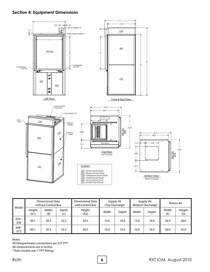
NotesAll Desuperheater connections are 3/4” FPT.All measurements are in inches.* Roth models use 1” FPT fittings
Left View
E
C
.975.50
DD
Power Supply 1/2”
High Voltage Supply 1”
Condensate3/4” FPTCondensate
3/4” FPT
ASP
ASP
Air Coil
1.13
CAP
BSP
CSP
SAP
SAP
AccessPanels
Low Votage 1/2”
Control PanelPlug Plate
Filter Rack
PlenumFlanges
LEGEND:
SAP = Service Access PanelBSP = Blower Service PanelCSP = Compressor Service PanelCAP= Control Access PanelASP = Access Service PanelFPT = Female Pipe Thread
Notes:1. All line and low voltage wiring must adhere to the National Electrical Code and local codes, whichever is the most stringent. 2. Wire length based on a one way measurement with a 2% voltage drop. 3. Wire size based on 60°C copper conductor and minimum circuit ampacity. 3. All fuses class RK-5.4. Min/Max Voltage: 208-230/60/1 = 197/243.* The external loop pump FLA is based on a maximum of three UP26-116F-230V pumps (1/2hp) for 048 - 072 and two pumps for 024 - 036.
9August 2010, RXT IOM Roth
Section 7: Unit Placement
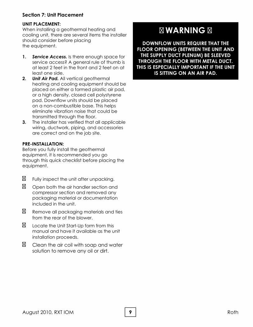
UNIT PLACEMENT:When installing a geothermal heating and cooling unit, there are several items the installer should consider before placing the equipment.
1. Service Access. Is there enough space for service access? A general rule of thumb is at least 2 feet in the front and 2 feet on at least one side.
2. Unit Air Pad. All vertical geothermal heating and cooling equipment should be placed on either a formed plastic air pad, or a high density, closed cell polystyrene pad. Downflow units should be placed on a non-combustible base. This helps eliminate vibration noise that could be transmitted through the floor.
3. The installer has verified that all applicable wiring, ductwork, piping, and accessories are correct and on the job site.
PRE-INSTALLATION:Before you fully install the geothermal equipment, it is recommended you go through this quick checklist before placing the equipment.
⚠ Fully inspect the unit after unpacking.
⚠ Open both the air handler section and compressor section and removed any packaging material or documentation included in the unit.
⚠ Remove all packaging materials and ties from the rear of the blower.
⚠ Locate the Unit Start-Up form from this manual and have it available as the unit installation proceeds.
⚠ Clean the air coil with soap and water solution to remove any oil or dirt.
⚠ WARNING ⚠DOWNFLOW UNITS REqUIRE THAT THE
FLOOR OPENING (BETWEEN THE UNIT AND THE SUPPLy DUCT PLENUM) BE SLEEvED
THROUGH THE FLOOR WITH METAL DUCT. THIS IS ESPECIALLy IMPORTANT IF THE UNIT
IS SITTING ON AN AIR PAD.
10Roth RXT IOM, August 2010
Section 7a: Unit Conversion
UNIT CONvERSION:Units are shipped in the left hand return air, upflow configuration. The control box is shipped inside the unit. The control box plugs into the special mounting plate on the top of the unit.
To convert the unit to right hand return air:1. Remove the front panels and rear panels. 2. Rotate the unit to the correct position. 3. Move the unit controls connection plate
from its current position (on the top of the unit) to the opposite side of the top of the unit. Use the block off plate from that side to cover the other side.
4. Mount the control box on what is now the top front of the unit. Plugs are available now to facilitate this.
5. Replace the front and rear panels onto the unit.
To convert the unit to downflow supply air:1. Remove the screws holding the blower and
heater housing and drop the assembly down.
2. Remove the block off plate from the area under the blower housing on the bottom blower area panel.
3. Place the block off plate over the opening where the blower housing was.
4. Install the downflow duct kit (instruction included with kit, ordered and shipped separately) in the compressor section of the unit.
5. Install the heater and blower housing assembly onto the downflow opening in the blower section securing it with the screws previously removed. The source, hot water generator, and
condensate fittings are on the air coil side of the unit, under the air coil itself. These connections are easier to facilitate if done prior to the fitting of the return air drop.
Figure 2: Blower Housing Connections
Figure 1: Unit Conversion
11August 2010, RXT IOM Roth
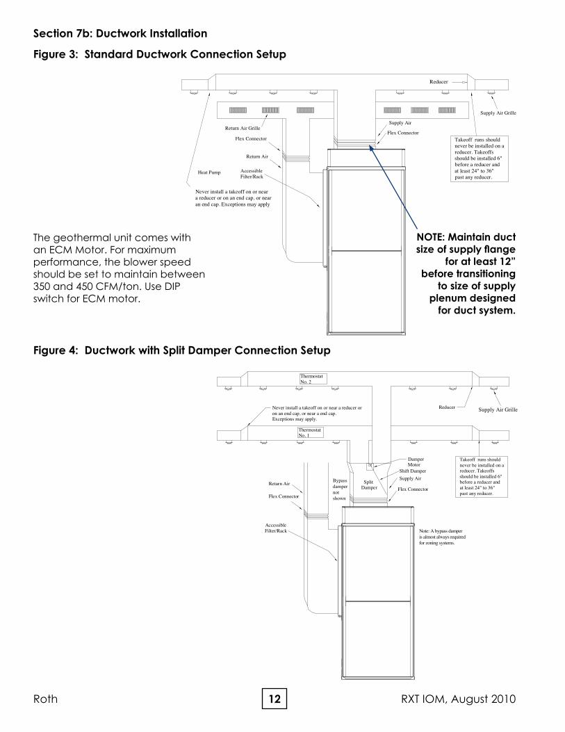
DUCT WORk:All new ductwork shall be designed as outlined in Sheet Metal and Air Conditioning Contractors National Association (SMACNA) or Air Conditioning Contractors of America (ACCA) or American Society of Heating, Refrigerating and Air Conditioning Engineers (ASHRAE) handbooks.
All supply/return plenums should be isolated from the unit by a flexible connector (canvas) or equivalent to prevent transfer of vibration noise to the ductwork. The flex connector should be designed so as not to restrict airflow. Turning vanes should be used on any run over 500 CFM. If the unit is installed in a noninsulated space the metal ductwork should be insulated on the inside with fiberglass insulation or similar insulation to prevent heat loss/gain and to absorb air noise. If the unit is being installed with existing ductwork, the ductwork must be designed to handle the air volume required by the unit being installed. When running a cooling or heating load on a building, size ductwork accordingly to the building design load and heat pump CFM.
Industry Standard: When sizing ductwork use 400 CFM per Ton.
As a general rule, maximum recommended face velocity for a supply outlet used in a residential application is 800 FPM. Maximum recommended return grille velocity is 400 FPM. Systems with higher velocity, are likely to have noise problems.
In buildings where ceilings are 8 feet or more, at least 50 percent of the return air should be taken back to the heat pump from the ceiling or high sidewall location and not more than 50 percent from the floor or low sidewall location.
Section 7b: Ductwork Installation
Location Supply Return
Main Ducts 900 FPM 600 FPM
Branch Ducts 700 FPM 600 FPM
Grills, Registers, Diffusers 750 FPM 600 FPM
Table 1: Maximum Air velocities
12Roth RXT IOM, August 2010
AccessibleFilter/Rack
Heat Pump
Flex Connector
Return Air
Flex Connector
Supply Air
Reducer
Never install a takeoff on or neara reducer or on an end cap, or nearan end cap. Exceptions may apply
Takeoff runs should never be installed on a reducer. Takeoffs should be installed 6" before a reducer and at least 24" to 36" past any reducer.
Return Air Grille
Supply Air Grille
Section 7b: Ductwork Installation
Figure 3: Standard Ductwork Connection Setup
The geothermal unit comes with an ECM Motor. For maximum performance, the blower speed should be set to maintain between 350 and 450 CFM/ton. Use DIP switch for ECM motor.
Figure 4: Ductwork with Split Damper Connection Setup
NOTE: Maintain duct size of supply flange
for at least 12” before transitioning
to size of supply plenum designed
for duct system.
Flex Connector
AccessibleFilter/Rack
Return AirSupply Air
Flex Connector Split Damper
DamperMotor
Thermostat No. 1
Thermostat No. 2
ReducerNever install a takeoff on or near a reducer oron an end cap, or near a end cap. Exceptions may apply.
Takeoff runs should never be installed on a reducer. Takeoffs should be installed 6" before a reducer and at least 24" to 36" past any reducer.
Shift Damper
Supply Air Grille
Note: A bypass damperis almost always requiredfor zoning systems.
Bypassdampernotshown
13August 2010, RXT IOM Roth
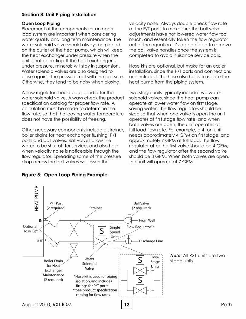
Open Loop PipingPlacement of the components for an open loop system are important when considering water quality and long term maintenance. The water solenoid valve should always be placed on the outlet of the heat pump, which will keep the heat exchanger under pressure when the unit is not operating. If the heat exchanger is under pressure, minerals will stay in suspension. Water solenoid valves are also designed to close against the pressure, not with the pressure. Otherwise, they tend to be noisy when closing.
A flow regulator should be placed after the water solenoid valve. Always check the product specification catalog for proper flow rate. A calculation must be made to determine the flow rate, so that the leaving water temperature does not have the possibility of freezing.
Other necessary components include a strainer, boiler drains for heat exchanger flushing, P/T ports and ball valves. Ball valves allow the water to be shut off for service, and also help when velocity noise is noticeable through the flow regulator. Spreading some of the pressure drop across the ball valves will lessen the
velocity noise. Always double check flow rate at the P/T ports to make sure the ball valve adjustments have not lowered water flow too much, and essentially taken the flow regulator out of the equation. It’s a good idea to remove the ball valve handles once the system is completed to avoid nuisance service calls.
Hose kits are optional, but make for an easier installation, since the P/T ports and connections are included. The hose also helps to isolate the heat pump from the piping system.
Two-stage units typically include two water solenoid valves, since the heat pump can operate at lower water flow on first stage, saving water. The flow regulators should be sized so that when one valve is open the unit operates at first stage flow rate, and when both valves are open, the unit operates at full load flow rate. For example, a 4 ton unit needs approximately 4 GPM on first stage, and approximately 7 GPM at full load. The flow regulator after the first valve should be 4 GPM, and the flow regulator after the second valve should be 3 GPM. When both valves are open, the unit will operate at 7 GPM.
Section 8: Unit Piping Installation
Figure 5: Open Loop Piping Example
IN
OUT
S
HEA
T PU
MP
SingleSpeedUnits
S
S
Two-StageUnits
Boiler Drainfor Heat
ExchangerMaintenance(2 required)
P/T Port(2 required) Strainer
Ball Valve(2 required)
Flow Regulator**
WaterSolenoid
Valve
**See product specification catalog for flow rates.
OptionalHose Kit*
*Hose kit is used for piping isolation, and includes fittings for P/T ports.
From Well
Discharge Line
Note: All RXT units are two-stage units.
14Roth RXT IOM, August 2010
Water qualityThe quality of the water used in geothermal systems is very important. In closed loop systems the dilution water (water mixed with antifreeze) must be of high quality to ensure adequate corrosion protection. Water of poor quality contains ions that make the fluid “hard” and corrosive. Calcium and magnesium hardness ions build up as scale on the walls of the system and reduce heat transfer. These ions may also react with the corrosion inhibitors in glycol based heat transfer fluids, causing them to precipitate out of solution and rendering the inhibitors ineffective in protecting against corrosion. In addition, high concentrations of corrosive ions, such as chloride and sulfate, will eat through any protective layer that the corrosion inhibitors form on the walls of the system.
Ideally, de-ionized water should be used for dilution with antifreeze solutions since de-
ionizing removes both corrosive and hardness ions. Distilled water and zeolite softened water are also acceptable. Softened water, although free of hardness ions, may actually have increased concentrations of corrosive ions and, therefore, its quality must be monitored. It is recommended that dilution water contain less than 100 PPM calcium carbonate or less than 25 PPM calcium plus magnesium ions; and less than 25 PPM chloride or sulfate ions.
In an open loop system the water quality is of no less importance. Due to the inherent variation of the supply water, it should be tested prior to making the decision to use an open loop system. Scaling of the heat exchanger and corrosion of the internal parts are two of the potential problems. The Department of Natural Resources or your local municipality can direct you to the proper testing agency. Please see Table 2 for guidelines.
Potential Problem Chemical(s) or Condition Range for Copper
Heat ExchangersRange for Cupro-Nickel Heat
Exchangers
Scaling Calcium & Magnesium Cabonate Less than 350 ppm Less than 350 ppm
Corrosion
pH Range 7 - 9 5 - 9
Total Disolved Solids Less than 1000 ppm Less than 1500 ppm
Ammonia, Ammonium Hydroxide Less than 0.5 ppm Less than 0.5 ppm
Ammonium Chloride, Ammonium Nitrate Less than 0.5 ppm Less than 0.5 ppm
Calcium Chloride / Sodium Chloride Less than 125 ppm Less than 125 ppm - Note 4
Chlorine Less than 0.5 ppm Less than 0.5 ppm
Hydrogen Sulfide None Allowed None Allowed
Biological Growth
Iron Bacteria None Allowed None Allowed
Iron Oxide Less than 1 ppm Less than 1 ppm
ErosionSuspended Solids Less than 10 ppm Less than 10 ppm
Water Velocity Less than 8 ft/s Less than 12 ft/s
Notes:1. Harness in ppm is equivalent to hardness in mg/l.2. Grains/gallon = ppm divided by 17.1.3. Copper and cupro-nickel heat exchangers are not recommended for pool applications for water outside the range of the table. Secondary heat exchangers are required for applications not meeting the requirements shown above.4. Saltwater applications (approx. 25,000 ppm) require secondary heat exchangers due to copper piping between the heat exchanger and the unit fittings.
Table 2: Water quality
Section 8: Unit Piping Installation
15August 2010, RXT IOM Roth
Section 8: Unit Piping Installation
Interior PipingAll interior piping must be sized for proper flow rates and pressure loss. Insulation should be used on all inside piping when minimum loop temperatures are expected to be less than 50°F. Use the table below for insulation sizes with different pipe sizes. All pipe insulation should be a closed cell and have a minimum wall thickness of 3/8”. All piping insulation should be glued and sealed to prevent condensation and dripping. Interior piping may consist of the following materials: HDPE, copper, brass, or rubber hose (hose kit only). PvC is not allowed on pressurized systems.
Table 3: Pipe Insulation
Typical Pressurized Flow Center InstallationThe flow centers are insulated and contain all flushing and circulation connections for residential and light commercial earth loops that require a flow rate of no more than 20 gpm. 1-1/4” fusion x 1” double o-ring fittings (AGA6PES) are furnished with the double o-ring flow centers for HDPE loop constructions. Various fittings are available for the double o-ring flow centers for different connections. See table 1 for connection options. A typical installation will require the use of a hose kit. Matching hose kits come with double o-ring adapters to transition to 1” hose connection.
Note: Threaded flow centers all have 1” FPT connections. Matching hose kits come with the AGBA55 adapter needed to transition from 1” FPT to 1” hose.
Piping Material Insulation Description
1” IPS Hose 1-3/8” ID - 3/8” Wall
1” IPS PE 1-1/4” ID - 3/8” Wall
1-1/4” IPS PE 1-5/8” ID - 3/8” Wall
2” IPS PD 2-1/8” ID - 3/8” Wall
Figure 6: Typical Single Unit Piping Connection (Pressurized Flow Center)
Note: P/T ports should be angled away from the unit for ease of gauge reading.
Air Coil
Source Water Out
Source Water In
~~
FlowCenter
HoseKit
To/FromLoop Field
P/T Ports
16Roth RXT IOM, August 2010
Typical Non-Pressurized Flow Center InstallationStanding column flow centers are designed to operate with no static pressure on the earth loop. The design is such that the column of water in the flow center is enough pressure to prime the pumps for proper system operation and pump reliability. The flow center does have a cap/seal, so it is still a closed system, where the fluid will not evaporate. If the earth loop header is external, the loop system will still need to be
flushed with a purge cart. The non-pressurized flow center needs to be isolated from the flush cart during flushing because the flow center is not designed to handle pressure. Since this is a non-pressurized system, the interior piping can incorporate all the above-mentioned pipe material options (see interior piping), including PVC. The flow center can be mounted to the wall with the included bracket or mounted on the floor as long as it is properly supported.
Figure 7: Typical Single Unit Piping Connection (Non-Pressurized Flow Center)
Section 8: Unit Piping Installation
17August 2010, RXT IOM Roth
Condensation Drain ConnectionConnect the EZ-Trap to the condensate drain on the equipment drain connection. The condensation line must be trapped a minimum of 1.0” as shown on diagram. The condensation line should be pitched away from the unit a minimum of 1/8” per foot. The top of trap must be below the drain connection. For more information on installing EZ-Trap, see installation sheet that comes with the EZ-Trap Kit.
Note: Connect the drain through the trap to the condensation drain system in conformance to local plumbing codes.
Part Number DescriptionACDT1A EZ-Trap ¾” KitACDT2A EZ-Trap 1” Kit
Figure 8: Condensation Drain Connection
1.0"
Cleaning Holes (Capped)
2.5" 1/8" per foot
Vent
Secondary drain pan (Horizontal Untis)
Section 8: Unit Piping Installation
18Roth RXT IOM, August 2010
Antifreeze Overview In areas where minimum entering loop temperatures drop below 40°F, or where piping will be routed through areas subject to freezing, antifreeze is required. Alcohols and glycols are commonly used as antifreeze. However, local and state/provincial codes supersede any instructions in this document. The system needs antifreeze to protect the coaxial heat exchanger from freezing and rupturing. Freeze protection should be maintained to 15°F below the lowest expected entering loop temperature. For example, if 30°F is the minimum expected entering loop temperature, the leaving loop temperature could be 22 to 25°F. Freeze protection should be set at 15°F (30-15 = 15°F). To determine antifreeze requirements, calculate how much volume the system holds. Then, calculate how much antifreeze will be needed by determining the percentage of antifreeze required for proper freeze protection. See Tables 3 and 4 for volumes and percentages. The freeze protection should be checked during installation using the proper hydrometer to measure the specific gravity and freeze protection level of the solution.
Antifreeze CharacteristicsSelection of the antifreeze solution for closed loop systems require the consideration of many important factors, which have long-term implications on the performance and life of the equipment. Each area of concern leads to a different “best choice” of antifreeze. There is no “perfect” antifreeze. Some of the factors to consider are as follows (Brine = antifreeze solution including water):
Safety: The toxicity and flammability of the brine (especially in a pure form).
Cost: Prices vary widely.
Thermal Performance: The heat transfer and viscosity effect of the brine.
Corrosiveness: The brine must be compatible with the system materials.
Stability: Will the brine require periodic change out or maintenance?
Convenience: Is the antifreeze available and easy to transport and install?
Codes: Will the brine meet local and state/provincial codes?
The following are some general observations about the types of brines presently being used:
Methanol: Wood grain alcohol that is considered toxic in pure form. It has good heat transfer, low viscosity, is non-corrosive, and is mid to low price. The biggest down side is that it is flammable in concentrations greater than 25%.
Ethanol: Grain alcohol, which by the ATF (Alcohol, Tobacco, Firearms) department of the U.S. government, is required to be denatured and rendered unfit to drink. It has good heat transfer, mid to high price, is non-corrosive, non-toxic even in its pure form, and has medium viscosity. It also is flammable with concentrations greater than 25%. Note that the brand of ethanol is very important. Make sure it has been formulated for the geothermal industry. Some of the denaturants are not compatible with HDPE pipe (for example, solutions denatured with gasoline).
Propylene Glycol: Non-toxic, non-corrosive, mid to high price, poor heat transfer, high viscosity when cold, and can introduce micro air bubbles when adding to the system. It has also been known to form a “slime-type” coating inside the pipe. Food grade glycol is recommended because some of the other types have certain inhibitors that react poorly with geothermal systems. A 25% brine solution is a minimum required by glycol manufacturers, so that bacteria does not start to form.
Ethylene Glycol: Considered toxic and is not recommended for use in earth loop applications.
GS4 (PoTASSIUM ACETATE): Considered highly corrosive (especially if air is present in the system) and has a very low surface tension, which causes leaks through most mechanical fittings. This brine is not recommended for use in earth loop applications.
Section 9: Antifreeze
19August 2010, RXT IOM Roth
Notes: 1. Consult with your representative or
distributor if you have any questions regarding antifreeze selection or use.
2. All antifreeze suppliers and manufacturers recommend the use of either de-ionized or distilled water with their products.
Antifreeze ChargingCalculate the total amount of pipe in the system and use Table 3 to calculate the amount of volume for each specific section of the system. Add the entire volume together, and multiply that volume by the proper antifreeze percentage needed (Table 4) for the freeze protection required in your area. Then, double check calculations during installation with the proper hydrometer and specific gravity chart (Figure 9) to determine if the correct amount of antifreeze was added.
⚠ CAUTION ⚠Use extreme care when opening, pouring, and mixing flammable
antifreeze solutions. Remote flames or electrical sparks can ignite undiluted antifreezes and vapors. Use only in a
well ventilated area. Do not smoke when handling flammable solutions. Failure to observe safety precautions may result in fire, injury, or death. Never work with
NoTE: Most manufacturers of antifreeze solutions recommend the use of de-ionized water. Tap water may include chemicals that could react with the antifreeze solution.
Type of AntifreezeMinimum Temperature for Freeze Protection
Drain Valve• (1) p/n 11-08-0005-001, ¾” MPT x 3-1/2” Brass
Nipple• (3) p/n 11-08-0006-001, ½” SWT x ¾” MPT
Copper Adaptor• (1) p/n 11-08-0007-001, ¾” x ¾” x ½” SWT
Copper Tee
Plumbing Installation
NOTE: All plumbing and piping connections must comply with local plumbing codes.
TIP: Measure the distance above the floor or shelf that the water heater is setting on, to where the drain valve is located. This distance must be greater than one-half the width of the tee you’re about to install, or you won’t be able to thread the tee on to the water heater.
1. Disconnect electricity to water heater.
2. Turn off water supply to water heater.
3. Drain water heater. Open pressure relief valve.
4. Remove drain valve and fitting from water heater.
5. Thread the ¾” MPT x 3-1/2” nipple into the water heater drain port. Use Teflon tape, or pipe dope on threads.
6. Thread the center port of the ¾” brass tee to the other end of the nipple.
7. Thread one of the copper adaptors into the end of the tee closest to the heat pump.
8. Thread the drain valve into the other end of the nipple. See Figure 10.
9. Above the water heater, cut the incoming cold water line. Remove a section of that line to enable the placement of the copper tee.
10. Insert the copper tee in the cold water line. See Figure 11.
11. Thread the remaining two ½”SWT x ¾”MPT copper adaptors into the ¾” FPT fittings on the heat pump, marked HOT WATER IN and HOT WATER OUT.
12. Run interconnecting ½” copper pipe from the HOT WATER OUT on the heat pump, to the copper adaptor located on the tee at the bottom of the water heater (Step 7).
13. Run interconnecting ½” copper pipe from the HOT WATER IN on the heat pump, to the copper tee in the cold water line (Step 10).
14. Install an air vent fitting at the highest point of the line from step 13 (assuming it’s the higher of the two lines from the heat pump to the water heater). See Figure 11.
15. Turn the water supply to the water heater on. Fill water heater.
Section 10: Desuperheater Installation
Desuperheater InstallationUnits that ship with the desuperheater function also ship with a connection kit.
Note: Desuperheater capacity is based on 0.4 GPM Flow per nominal ton at 90°F entering hot water temperature.
Note: Units that are shipped with a desuperheater do not have the desuperheater pump wires connected to the electrical circuit, to preclude accidentally running the pump while dry. Pump has to be connected to the electric circuit (master contactor) when the lines from the water heater are installed & air is removed.
22Roth RXT IOM, August 2010
16. Flush the interconnecting lines, and check for leaks.
17. Install 3/8” closed cell insulation on the lines connecting the heat pump to the water heater.
18. Reconnect electricity to water heater.
Figure 10: Water Heater Connection kit Assembly for Bottom of Water Heater
Connection to HotWater Tank
Brass Tee
Adapter to UnitWater Line
Drain
Copper TeeFor Domestic Cold Water In Line
NOTE: Drawing shown vertically for detail. Fitting installs horizontally into hot water tank.
Section 10: Desuperheater Installation
23August 2010, RXT IOM Roth
Figure 11: Typical Desuperheater Installation
Section 10: Desuperheater Installation
Figure 12: Desuperheater Installation with Preheat Tank
Drain Valve Fitting Kit
HotWaterTank
ColdLine
In
HotLineOut
Venting Waste Valve orVent Coupling
P/TReliefValve
Air Coil
HWG In
HWG Out
CopperTee
Hot Water Out
Hot Water In
3/4” CopperAdapter Fitting
Unit WaterConnection Detail
Air Coil
HWG In
HWG Out
Drain Valve Fitting Kit
HotWaterTank
ColdLine
In
Venting Waste Valve orVent Coupling
P/TReliefValve
CopperTee
Hot Water Out
Hot Water In
3/4” CopperAdapter Fitting
Unit WaterConnection Detail
HotLineOut
HotWaterTank
(Powered)
HotLineOut
ColdLine
In
24Roth RXT IOM, August 2010
MICROPROCESSOR FEATURES AND OPERATION Roth’s geothermal heat pump controls provide a unique modular approach for controlling heat pump operation. The control system uses one, two, or three printed circuit boards, depending upon the features of a particular unit. This approach simplifies installation and troubleshooting, and also eliminates features that are not applicable for some units.
A microprocessor-based printed circuit board controls the inputs to the unit as well as outputs for status mode, faults, and diagnostics. A status LED and an LED for each fault is provided for diagnostics. An ECM control module provides field selectable options for airflow and dehumidification mode, plus an LED to indicate CFM (100 CFM per flash). If the combination unit is desired (combination water-to-air and water-to-water heat pump), a third board controls the hydronic portion of the unit, allowing field selectable hot water/forced air priority and other options.
Removable low voltage terminal strips provide all necessary terminals for field connections. Not only are the thermostat inputs included, but there are also two additional removable terminal strips for all of the accessory and electric heat wiring for ease of installation and troubleshooting. Startup/Random StartThe unit will not operate until all the inputs and safety controls are checked for normal conditions. At first power-up, the compressor is energized after a five minute delay. In addition, a zero to sixty second random start delay is added at first power-up to avoid multiple units from being energized at the same time.
Short Cycle Protection A built-in five minute anti-short cycle timer provides short cycle protection of the compressor.
Component Sequencing DelaysComponents are sequenced and delayed for optimum space conditioning performance and to make any startup noise less noticeable.
Test Mode
The microprocessor control allows the technician to shorten most timing delays for faster diagnostics by changing the position of a jumper located on the lockout board.
Water Solenoid valve Connections Two accessory relay outputs at the terminal strip provide a field connection for two types of water solenoid valves, a standard 24VAC solenoid valve, or a 24VAC solenoid valve with an end switch. Additional field wiring is no longer required for operation of the end switch.
Humidifier/Dehumidification Connections Connections for a humidistat are provided, which automatically engages the fan when the humidistat contact closes. In addition, a field connection is provided at the terminal strip for external control of the On Demand Dehumidification (ODD) feature for the variable speed ECM motor (when equipped), which automatically lowers the fan speed when the space humidity is higher than set point. Either connection may be used with a thermostat that includes humidifier/dehumidification outputs. Not applicable for splits/water-to-water.
Airflow Monitor (Units with ECM Motor) An LED on the ECM control module flashes one time per 100 CFM when the unit’s fan is operating to indicate airflow.
Resistance Heat Control The electric heat control module contains the appropriate high-voltage control relays. Low voltage control signals from the compressor section energize the relays in the electric heat module to engage backup electric heat when necessary.
Electronic Condensate Overflow Protection The control board utilizes an impedance sensing liquid sensor at the top of the drain pan. Since the drain pan is grounded, when water touches the sensor for 30 continuous seconds, the sensor sends a ground signal to the lockout board, indicating that a condensate overflow fault has occurred.
Section 11a: Controls
25August 2010, RXT IOM Roth
Loop Pump Circuit Breakers (Single Compressor Units)The loop pump(s) and desuperheater pump are protected by control box mounted circuit breakers for easy wiring of pumps during installation. Circuit breakers eliminate the need to replace fuses.
Safety Controls The control receives separate signals for high pressure, low pressure, low water flow, and condensate overflow faults. Upon a continuous 30-second measurement of the fault (immediate for high pressure), compressor operation is suspended (see Fault Retry below), and the appropriate LED flashes. Once the unit is locked out (see Fault Retry below), an output (terminal “L”) is made available to a fault LED at the thermostat (water-to-water unit has fault LED on the corner post).
Low Pressure: If the low pressure switch is open for 30 continuous seconds, the compressor operation will be interrupted, and the control will go into fault retry mode. At startup, the low pressure switch is not monitored for 90 seconds to avoid nuisance faults.
High Pressure: If the high pressure switch opens, the compressor operation will be interrupted, and the control will go into fault retry mode. There is no delay from the time the switch opens and the board goes into fault retry mode. There is also no delay of switch monitoring at startup.
Flow Switch: If the flow switch is open for 30 continuous seconds, the compressor operation will be interrupted, and the control will go into fault retry mode. At startup, the flow switch is not monitored for 30 seconds to avoid nuisance faults.
Condensate Overflow: If water touches the condensate overflow sensor for 30 continuous seconds, the compressor operation will be interrupted, and the control will go into fault retry mode. There is no delay of switch monitoring at startup.
FAULT RETRy All faults are retried twice before finally locking the unit out. The fault retry feature is designed to prevent nuisance service calls. There is an anti-short cycle period between fault retries. On the third fault, the board will go into lockout mode.
Over/Under voltage Shutdown The lockout board protects the compressor from operating when an over/under voltage condition exists. The control monitors secondary voltage (24VAC) to determine if an over/under voltage condition is occurring on the primary side of the transformer. For example, if the secondary voltage is 19 VAC, the primary voltage for a 240V unit would be approximately 190V, which is below the minimum voltage (197V) recommended by the compressor manufacturer. This feature is self-resetting. If the voltage comes back within range, normal operation is restored. Therefore, over/under voltage is not a lockout.
Under voltage (18 VAC) causes the compressor to disengage and restart when the voltage returns to 20 VAC. Over voltage (31 VAC) causes the compressor to disengage and restart when the voltage returns to 29 VAC. During an over or under voltage condition, all five fault LEDs will blink (HP + LP + FS + CO + Status). When voltage returns to normal operation, the four fault LED’s will stop blinking, but the status LED will continue to flash. While the board LEDs are flashing, the thermostat fault light will be illuminated.
Section 11a: Controls
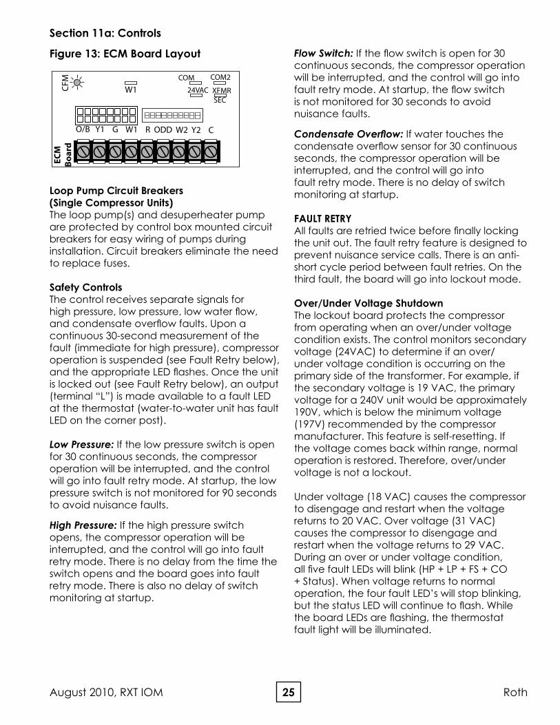
O/B Y1 G W1 R ODD W2 Y2 C
W1
COM
24VAC
COM2
XFMRSEC
CFM
ECM
Bo
ard
Figure 13: ECM Board Layout
26Roth RXT IOM, August 2010
Intelligent Reset If the thermostat is powered off and back on (soft reset), the board will reset, but the last fault will be stored in memory for ease of troubleshooting. If power is interrupted to the board, the fault memory will be cleared.
Lockout with Emergency HeatWhile in lockout mode, if the thermostat is calling for backup heat, emergency heat mode will occur.
Diagnostics The lockout board includes five LEDs (status, high pressure, low pressure, low water flow, condensate overflow) for fast and simple control board diagnosis. Below is a table showing LED function.
Section 11a: Controls
LED Color Location1 Function Normal Operation Fault Retry2 Lockout2
Green Top High Pressure OFF Flashing3 ON3
Orange 2nd Low Pressure OFF Flashing3 ON3
Red 3rd Water Flow OFF Flashing3 ON3
Yellow 4th Condensate Overflow OFF Flashing3 ON3
Green Bottom Status Flashing4 Flashing5 Flashing4
Notes:1. Looking at the board when the LEDs are on the right hand side.2. If all five lights are flashing, the fault is over/under voltage.3. Only the light associated with the particular fault/lockout will be on or flashing.
For example, if a high pressure lockout has occurred, the top green light will be on. The orange, red, and yellow lights will be off.
4. Status lights will be off when tin test mode.5. Flashes alternately with the fault LED.
Table 6: LED Identification
Hot Water Pump Control Controls for high water temperature and low compressor discharge line temperature prevent the hot water (desuperheater) pump from operating when the leaving water temperature is above 130°F, or when the compressor discharge line is too cool to provide adequate water heating.
Lockout Board jumper SelectionThe lockout board includes three jumpers for field selection of various board features.
Water Solenoid Valve Delay (WSD): When the WSD jumper is installed, the “A” terminal is energized when the compressor is energized. When the jumper is removed, the “A” terminal is energized 10 seconds after the compressor. If using the Taco water solenoid valve (or a valve with an end switch), the unit terminal strip includes a means for connecting a valve of this type. The WSD jumper should be installed. If
using a slow opening valve that does not have an end switch, the jumper should be removed.
Test Mode (TEST): When the TEST jumper is installed, the board operates in the normal mode. When the jumper is removed, the board operates in test mode, which speeds up all delays for easier troubleshooting. When service is complete, the jumper must be re-installed in order to make sure that the unit operates with normal sequencing delays.
over/Under Voltage Disable (o/V): When the O/V jumper is installed, the over/under voltage feature is active. When the jumper is removed, the over/under voltage feature is disabled. On rare occasions, variations in voltage will be outside the range of the over/under voltage feature, which may require removal of the jumper. However, removal of the jumper could cause the unit to run under adverse conditions, and therefore should not be removed without
27August 2010, RXT IOM Roth
Section 11a: Controls
Figure 14: Lockout Board Layout
ACRYLO
CCG
CC HPHPLPLPFSFSCOCO
LockoutBoard
Status
R2 R1 C2 C1
WSDTESTO/V
contacting technical services. An over/under voltage condition could cause premature component failure or damage to the unit controls. Any condition that would cause this fault must be thoroughly investigated before taking any action regarding the jumper removal. Likely causes of an over/under voltage condition include power company transformer selection, insufficient entrance wire sizing, defective breaker panel, incorrect transformer tap (unit control box), or other power-related issues.
SEqUENCE OF OPERATION: Water-to-Air Units, Single Compressor, ECM Fan
Heating, 1st Stage (Y1,G) Two-Stage Units The ECM fan is started immediately at 75% (of 1st stage operation) CFM level, first stage compressor and the loop/desuperheater pump(s) are energized 10 seconds after the “Y1” input is received, and the ECM fan adjusts to 100% (of 1st stage operation) CFM level 30 seconds after the “Y1” input.
Heating, 2nd Stage (Y1,Y2,G) Two-Stage Units The ECM fan adjusts to 2nd stage CFM level, and the compressor full load solenoid valve is energized.
Heat, 3rd Stage (Y1,Y2,W,G) Two-Stage Units The ECM fan remains at 100% of 2nd stage CFM level, and the electric backup heat is energized.
Emergency Heat (W,G) The fan is started immediately at 110% of 2nd stage CFM level, and the electric backup heat is energized.
Cooling operation The reversing valve is energized for cooling operation. Terminal “O” from the thermostat is connected to the reversing valve solenoid.
Cooling, 1st stage (Y1,0,G) Two-Stage UnitsThe ECM fan is started immediately at 75% (of 1st stage operation) CFM level, first stage compressor and the loop/desuperheater pump(s) are energized 10 seconds after the “Y1” input is received, and the ECM fan adjusts to 100% (of 1st stage operation) CFM level 30 seconds after the “Y1” input.
Cooling, 2nd Stage (Y1,Y2,o,G) Two-Stage Units The ECM fan adjusts to 2nd stage CFM level, and the compressor full load solenoid valve is energized.
Cooling, Dehumidification Mode The ECM control module includes two types of dehumidification modes, Forced Dehumidification mode, and On Demand Dehumidification (ODD). If the ECM control module is set to Forced Dehumidification mode, the ECM fan runs at normal CFM in all heating stages, but all cooling operation will be 85% of the current stage CFM level, which lowers the CFM through the evaporator coil, improving latent capacity. In ODD mode, a humidistat or a thermostat with a dehumidification output (output must be reverse logic -- i.e. it must operate like a humidistat) is connected to the ODD terminal. When the module receives a call for dehumidification, the fan runs at 85% of the current stage CFM in the cooling mode. Otherwise, the airflow is at the normal CFM level. The signal is ignored in the heating mode.
Fan only When the ECM control module receives a “G” call without a call for heating or cooling, the fan operates at 50% of the full load CFM level.
28Roth RXT IOM, August 2010
Section 11a: Controls
Table 7: ECM Fan Performance - Two-Stage Compressor Units
DIP SwitchMode Operation
S9 S10
ON OFF Normal Dehumidification mode disabled (normal Htg/Clg CFM) - factory setting
OFF ON ODD On Demand dehumidification mode (humidistat input at terminal ODD) - Humidistat required
OFF OFF Constant Dehum Constant dehumidification mode (always uses dehum CFM for cooling and normal CFM for heating) - No humidistat required
ON ON Not Used Not an applicable selection
Notes:1. ODD uses reverse logic, which allows a humidistat to be used for this feature instead of a dehumidistat.
To enter dehumidification mode, ODD input should be 0 VAC; for normal cooling CFM, ODD input should be 24VAC.2. Heating CFM is not affected by dehumidification mode. When in dehumidification mode, cooling CFM is 85% of normal
B 1050 1300 1050 1300 893 1105 650 OFF OFF ON OFF OFF OFF OFF OFF
C 900 1200 900 1200 765 1020 550 OFF OFF OFF OFF OFF OFF OFF OFF
D 850 1050 850 1050 500 OFF OFF OFF ON OFF OFF OFF OFF
048
A 1500 1750 1550 1850 1318 1573 925 ON OFF ON OFF ON OFF OFF OFF
B 1400 1650 1400 1700 1190 1445 850 OFF ON ON OFF OFF ON OFF OFF
C 1275 1500 1275 1550 775 OFF ON OFF OFF OFF ON OFF OFF
D 1150 1350 1150 1400 700 OFF ON OFF ON OFF ON OFF OFF
060
A 1800 2150 1750 2100 1488 1785 1050 OFF OFF ON OFF OFF OFF OFF OFF
B 1500 1750 1550 1850 1318 1573 925 ON OFF ON OFF ON OFF OFF OFF
C 1350 1600 1400 1675 825 ON OFF OFF OFF ON OFF OFF OFF
D 1225 1425 1250 1500 750 ON OFF OFF ON ON OFF OFF OFF
072
A - - - - - - - - - - - - - - -
B 1800 2150 1750 2100 1488 1785 1050 OFF OFF ON OFF OFF OFF OFF OFF
C 1625 1950 1600 1900 1360 1615 950 OFF OFF OFF OFF OFF OFF OFF OFF
D 1475 1750 1425 1700 850 OFF OFF OFF ON OFF OFF OFF OFF
Notes:1. Program B (Bold type) is factory settings and rated CFM. CFM is controlled within 5% up to the max. ESP. Max. ESP includes allowance for wet coil and standard filter.2. Power must be off to the unit for at least 3 seconds before the ECM motor will recognize a speed change.
29August 2010, RXT IOM Roth
Section 11a: Controls
30Roth RXT IOM, August 2010
Table 9: Auxiliary Heater Electrical Data
Note: * Not recommended for size 024** Not recommended for sizes 024-036
All wiring MUST be done in strict compliance with local, state, national or any other applicable codes.
Note: If Electric Auxiliary is used, never disconnect power to the heat unit as it may be required to properly heat the home.Major damage may result.
Please note, these heaters are for vertical units only.
Please see the Field-Installed Electric Heat IOM, part number 27P009-01NN for detailed instructions on the installation and wiring of auxiliary electric heaters.
Section 12: Accessories
Figure 15: Auxiliary Heater Placement
+
-
DCBridge
LED
Diode RY124VAC input from unit #1
+
-Diode RY2
24VAC input from unit #2
RY1
RY2
240VAC input
240VAC to pump(s)
24VAC 24VAC
Figure 1: Board Layout
Figure 2: Board Schematic
240V IN 240V OUT
Relay Relay
240VACPower Source
240VACto Pump(s)
24VACconnectionto unit #2
(compressor contactor coil)
24VACconnectionto unit #1
(compressor contactor coil)
APSMA PUMP SHARING MODULEThe pump sharing module, part number APS-MA, is designed to allow two units to share one flow center. With the APSMA module, either unit can energize the pump(s). Connect the units and flow center as shown in Figure 16, below. Figure 17 includes a schematic of the board. The module must be mounted in a NEMA enclosure or inside the unit control box. Local code supersedes any recommendations in this document.
Figure 16: APSMA Module Layout
Figure 17: APSMA Module Wiring Schematic
Representative drawing only, some models may vary in appearance.
Heater Support Rod Fits into Hole
Rotate Circuit Breakers 180 Degrees for RH and LH DN Airflow
31August 2010, RXT IOM Roth
Section 13: Troubleshooting
Table 10: Unit Heat of Extraction/Rejection Data (Full Load)
Two-Stage Water-to-Air Packaged Units (70°F EAT Heating; 80/67°F EAT Cooling)
Heat of Extraction/Rejection-Full Load Operation (Mbtuh) -- DSP Disconnected
EWT Flow Rate 024 036 048 060 072
°F GPM/Ton HE HR HE HR HE HR HE HR HE HR
30
1.5
Not available at time of Printing
18.6 25.9 31.1 38.7
2.25 21.0 27.3 32.9 42.0
3 21.4 29.1 33.7 42.5
50
1.5 25.1 48.6 37.7 64.6 41.8 80.2 51.5 85.2
2.25 28.1 49.1 39.6 64.7 44.1 80.7 55.7 87.0
3 28.7 49.1 42.0 65.1 45.1 81.3 56.4 88.1
70
1.5 31.3 47.0 47.6 61.9 52.5 76.4 65.4 81.0
2.25 35.1 47.3 50.0 61.9 55.3 76.7 70.4 82.5
3 35.8 47.3 52.9 62.2 56.5 77.2 71.2 83.4
90
1.5 37.6 44.8 52.6 58.7 62.4 72.4 80.5 77.8
2.25 42.0 45.1 55.3 58.6 65.6 72.4 86.7 79.0
3 43.0 45.1 58.6 58.7 67.0 72.7 87.7 79.7
110
1.5 41.8 55.4 68.4 73.2
2.25 41.9 55.1 68.2 73.9
3 41.9 55.1 68.4 74.5
NoTE: Always check HE or HR in Full Load operation with desuperheater disconnected.
32Roth RXT IOM, August 2010
Table 12: Two-Stage Unit Heat Exchanger Pressure Drop (Full Load)
Two-Stage Water-to-Air Packaged Units
Heat Exchanger Pressure Drop
Part Load Operation Pressure Drop at Entering Water Temp. Listed Below
Model Flow RateGPM
30°FPSI
50°FPSI
70°FPSI
90°FPSI
110°FPSI
024 Not available at time of printing
036
4.5 1.0 0.9 0.8 0.7 0.6
7.0 2.5 2.2 1.9 1.7 1.5
9.0 4.2 3.6 3.1 2.8 2.4
048
4.5 1.1 1.0 0.9 0.8 0.8
7.0 2.8 2.4 2.1 2.0 1.9
9.0 4.6 4.0 3.5 3.3 3.1
060
6.0 1.3 1.1 1.0 0.9 0.9
10.0 3.7 3.2 2.8 2.6 2.5
12.0 5.4 4.6 4.1 3.8 3.6
072
8.0 1.6 1.5 1.4 1.4 1.2
10.0 2.6 2.4 2.3 2.1 1.9
14.0 5.0 4.7 4.4 4.2 3.7
Two-Stage Water-to-Air Packaged Units
Heat Exchanger Pressure Drop
Full Load Operation Pressure Drop at Entering Water Temp. Listed Below
Model Flow RateGPM
30°FPSI
50°FPSI
70°FPSI
90°FPSI
110°FPSI
024 Not available at time of printing
036
4.5 1.0 0.9 0.8 0.7 0.6
7.0 2.5 2.2 1.9 1.7 1.5
9.0 4.2 3.6 3.1 2.8 2.4
048
6.0 2.0 1.8 1.6 1.4 1.4
9.0 4.6 4.0 3.5 3.3 3.1
12.0 8.2 7.0 6.3 5.8 5.5
060
7.5 2.1 1.8 1.6 1.5 1.4
11.5 4.9 4.2 3.7 3.4 3.3
15.0 8.4 7.2 6.4 5.9 5.6
072
9.0 2.1 1.9 1.8 1.7 1.5
14.0 5.0 4.7 4.4 4.2 3.7
16.0 6.6 6.1 5.8 5.4 4.9
Table 13: Two-Stage Unit Heat Exchanger Pressure Drop (Part Load)
Section 13: Troubleshooting
33August 2010, RXT IOM Roth
Heating - Without Desuperheater
EWT(°F)
GPMPer Ton
DischargePressure
(PSIG)
SuctionPressure
(PSIG)
SubCooling
(°F)
SuperHeat(°F)
AirTemperatureRise (°F-DB)
WaterTemperature
Drop (°F)
301.5 285-310 68-76 4-10 8-12 14-20 5-8
3 290-315 70-80 4-10 8-12 16-22 3-6
501.5 315-345 100-110 6-12 9-14 22-28 7-10
3 320-350 105-115 6-12 9-14 24-30 5-8
701.5 355-395 135-145 7-12 10-15 30-36 9-12
3 360-390 140-150 7-12 10-15 32-38 7-10
Cooling - Without Desuperheater
EWT(°F)
GPMPer Ton
DischargePressure
(PSIG)
SuctionPressure
(PSIG)
SubCooling
(°F)
SuperHeat(°F)
AirTemperatureDrop (°F-DB)
WaterTemperature
Rise (°F)
501.5 220-235 120-130 10-16 12-20 20-26 19-23
3 190-210 120-130 10-16 12-20 20-26 9-12
701.5 280-300 125-135 8-14 10-16 19-24 18-22
3 250-270 125-135 8-14 10-16 19-24 9-12
901.5 360-380 130-145 8-14 10-14 18-22 17-21
3 330-350 130-140 8-14 10-14 18-22 8-11
PERFORMANCE CHECkHeat of Extraction(HE)/Rejection(HR)Record information on the Unit Start-up Form
Equipment should be in operation for a minimum of 10 minutes in either mode – WITH THE HoT WATER GENERAToRTURNED oFF.
1. Determine flow rate in gallons per minute a. Check entering water temperature b. Check entering water pressure c. Check leaving water pressure
Once this information is recorded, find corresponding entering water temperature column in Specification Manual for unit.Find pressure differential in PSI column in Spec Manual. Then read the GPM column in Spec Manual to determine flow in GPM.
2. Check leaving water temperature of unit.FORMULA: [GPM x water temp diff, x 485 (antifreeze)] /500 (fresh water) = HE or HR in BTU/HR
A 10% variance from Spec Manual is allowed. Always use the same pressure gauge & temperature measuring device.Water flow must be in range of Specification Manual. If system has too much water flow, performance problems should be expected.
Section 13: Troubleshooting
Table 14: Unit Operating Pressures (R-410a)
34Roth RXT IOM, August 2010
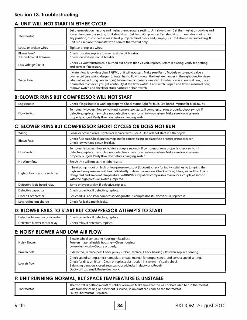
A: UNIT WILL NOT START IN EITHER CyCLE
Thermostat
Set thermostat on heating and highest temperature setting. Unit should run. Set thermostat on cooling and lowest temperature setting. Unit should run. Set fan to On position. Fan should run. If unit does not run in any position, disconnect wires at heat pump terminal block and jump R, G, Y. Unit should run in heating. If unit runs, replace thermostat with correct thermostat only.
Loose or broken wires Tighten or replace wires.
Blown Fuse/ Tripped Circuit Breakers
Check fuse size, replace fuse or reset circuit breaker.Check low voltage circuit breaker.
Low Voltage Circuit Check 24 volt transformer. If burned out or less than 24 volt, replace. Before replacing, verify tap setting and correct if necessary.
Water Flow
If water flow is low (less than 1 GPM), unit will not start. Make sure Pump Module or solenoid valve is connected (see wiring diagram). Water has to flow through the heat exchanger in the right direction (see labels at water fitting connections) before the compressor can start. If water flow is at normal flow, use an ohmmeter to check if you get continuity at the flow switch. If no switch is open and flow is a normal flow, remove switch and check for stuck particles or bad switch.
B: BLOWER RUNS BUT COMPRESSOR WILL NOT STARTLogic Board Check if logic board is working properly. Check status light for fault. See board imprint for blink faults.
Flow SwitchTemporarily bypass flow switch until compressor starts. If compressor runs properly, check switch. If defective, replace. If switch is not defective, check for air in loop system. Make sure loop system is properly purged. Verify flow rate before changing switch.
C: BLOWER RUNS BUT COMPRESSOR SHORT CyCLES OR DOES NOT RUNWiring Loose or broken wires. Tighten or replace wires. See A: Unit will not start in either cycle.
Blown Fuse Check fuse size. Check unit nameplate for correct sizing. Replace fuse or reset circuit breaker.Check low voltage circuit breaker.
Flow SwitchTemporarily bypass flow switch for a couple seconds. If compressor runs properly, check switch. If defective, replace. If switch is not defective, check for air in loop system. Make sure loop system is properly purged. Verify flow rate before changing switch. .
No Water flow See A: Unit will not start in either cycle.
High or low pressure switches
If heat pump is out on high or low-pressure cutout (lockout), check for faulty switches by jumping the high and low-pressure switches individually. If defective replace. Check airflow, filters, water flow, loss of refrigerant and ambient temperature. WARNING: Only allow compressor to run for a couple of seconds with the high pressure switch jumpered
Defective logic board relay Jump or bypass relay. If defective, replace.
Defective capacitor Check capacitor. If defective, replace.
Frozen Compressor See charts O and P for compressor diagnostic. If compressor still doesn’t run, replace it.
Low refrigerant charge Check for leaks and fix leaks.
D: BLOWER FAILS TO START BUT COMPRESSOR ATTEMPTS TO STARTDefective blower motor capacitor Check capacitor. If defective, replace.
Defective blower motor relay Check relay. If defective, replace.
Broken belt If defective, replace belt. Check pulleys. If bad, replace. Check bearings. If frozen, replace bearing.
Low air flow
Check speed setting, check nameplate or data manual for proper speed, and correct speed setting.Check for dirty air filter—Clean or replace; obstruction in system—Visually check.Balancing dampers closed, registers closed, leaks in ductwork. Repair.Ductwork too small. Resize ductwork.
F: UNIT RUNNING NORMAL, BUT SPACE TEMPERATURE IS UNSTABLE
ThermostatThermostat is getting a draft of cold or warm air. Make sure that the wall or hole used to run thermostat wire from the ceiling or basement is sealed, so no draft can come to the thermostat.Faulty Thermostat (Replace).
Section 13: Troubleshooting
35August 2010, RXT IOM Roth
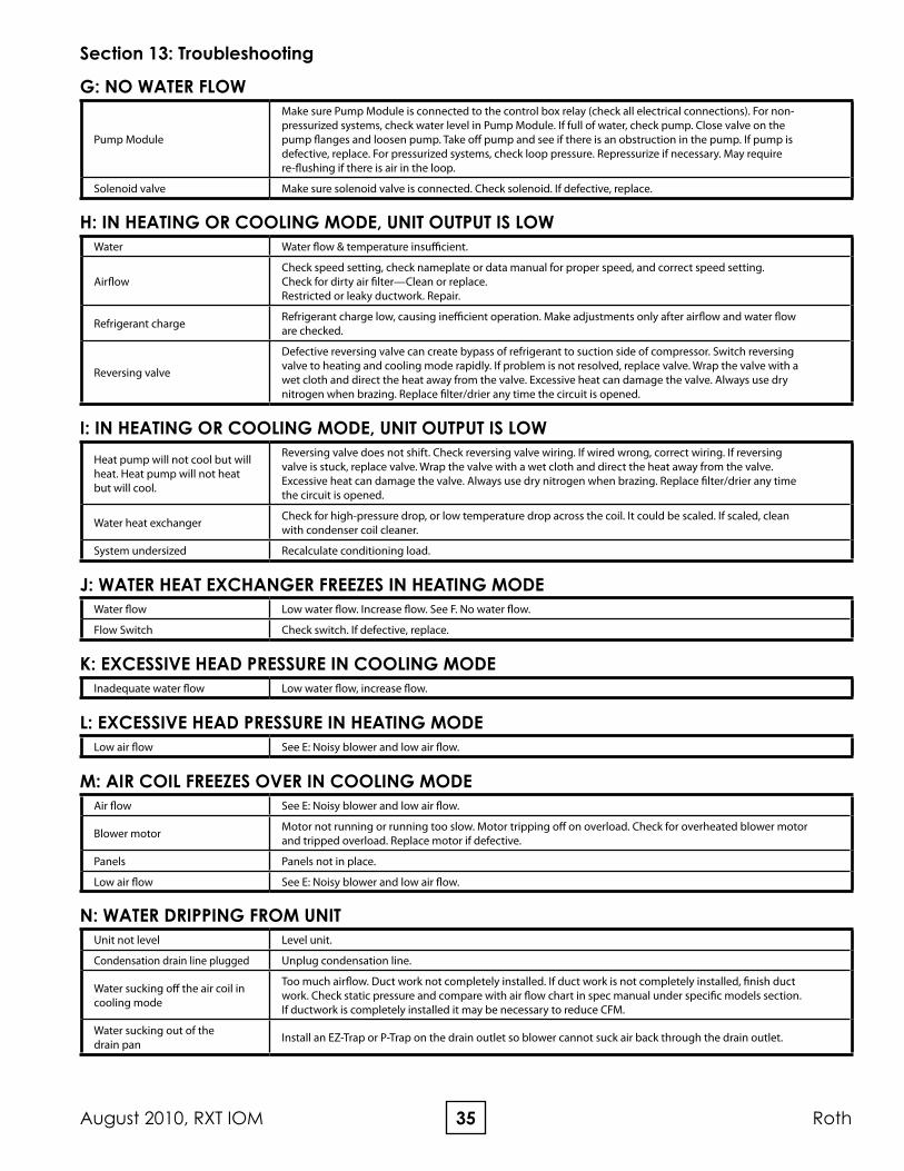
G: NO WATER FLOW
Pump Module
Make sure Pump Module is connected to the control box relay (check all electrical connections). For non-pressurized systems, check water level in Pump Module. If full of water, check pump. Close valve on the pump flanges and loosen pump. Take off pump and see if there is an obstruction in the pump. If pump is defective, replace. For pressurized systems, check loop pressure. Repressurize if necessary. May require re-flushing if there is air in the loop.
Solenoid valve Make sure solenoid valve is connected. Check solenoid. If defective, replace.
H: IN HEATING OR COOLING MODE, UNIT OUTPUT IS LOWWater Water flow & temperature insufficient.
AirflowCheck speed setting, check nameplate or data manual for proper speed, and correct speed setting.Check for dirty air filter—Clean or replace.Restricted or leaky ductwork. Repair.
Refrigerant charge Refrigerant charge low, causing inefficient operation. Make adjustments only after airflow and water flow are checked.
Reversing valve
Defective reversing valve can create bypass of refrigerant to suction side of compressor. Switch reversing valve to heating and cooling mode rapidly. If problem is not resolved, replace valve. Wrap the valve with a wet cloth and direct the heat away from the valve. Excessive heat can damage the valve. Always use dry nitrogen when brazing. Replace filter/drier any time the circuit is opened.
I: IN HEATING OR COOLING MODE, UNIT OUTPUT IS LOWHeat pump will not cool but will heat. Heat pump will not heat but will cool.
Reversing valve does not shift. Check reversing valve wiring. If wired wrong, correct wiring. If reversing valve is stuck, replace valve. Wrap the valve with a wet cloth and direct the heat away from the valve. Excessive heat can damage the valve. Always use dry nitrogen when brazing. Replace filter/drier any time the circuit is opened.
Water heat exchanger Check for high-pressure drop, or low temperature drop across the coil. It could be scaled. If scaled, clean with condenser coil cleaner.
System undersized Recalculate conditioning load.
j: WATER HEAT EXCHANGER FREEzES IN HEATING MODEWater flow Low water flow. Increase flow. See F. No water flow.
Flow Switch Check switch. If defective, replace.
k: EXCESSIvE HEAD PRESSURE IN COOLING MODEInadequate water flow Low water flow, increase flow.
L: EXCESSIvE HEAD PRESSURE IN HEATING MODELow air flow See E: Noisy blower and low air flow.
M: AIR COIL FREEzES OvER IN COOLING MODEAir flow See E: Noisy blower and low air flow.
Blower motor Motor not running or running too slow. Motor tripping off on overload. Check for overheated blower motor and tripped overload. Replace motor if defective.
Panels Panels not in place.
Low air flow See E: Noisy blower and low air flow.
N: WATER DRIPPING FROM UNITUnit not level Level unit.
Condensation drain line plugged Unplug condensation line.
Water sucking off the air coil in cooling mode
Too much airflow. Duct work not completely installed. If duct work is not completely installed, finish duct work. Check static pressure and compare with air flow chart in spec manual under specific models section. If ductwork is completely installed it may be necessary to reduce CFM.
Water sucking out of the drain pan Install an EZ-Trap or P-Trap on the drain outlet so blower cannot suck air back through the drain outlet.
Section 13: Troubleshooting
36Roth RXT IOM, August 2010
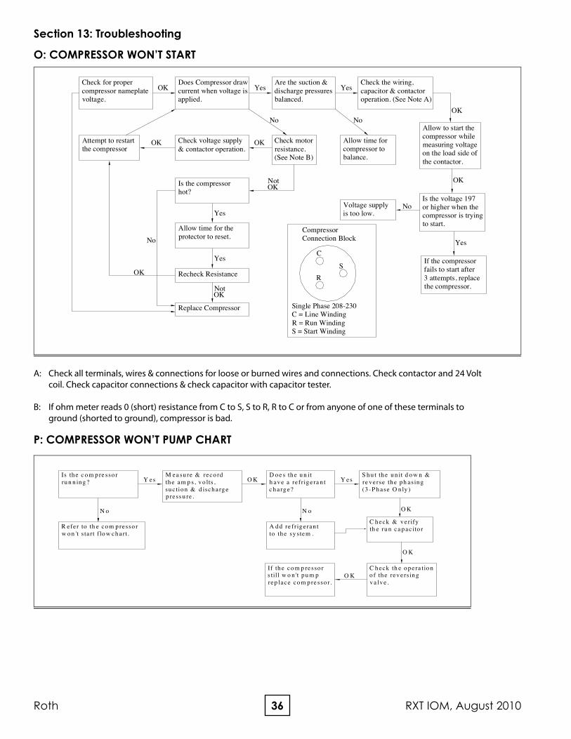
Check for proper compressor nameplate voltage.
Attempt to restartthe compressor
OK
Allow to start the compressor while measuring voltageon the load side ofthe contactor.
Allow time for compressor to balance.
OK Check motorresistance.(See Note B)
OKCheck voltage supply& contactor operation.
Compressor Connection Block
S
Replace Compressor
NotOK
Yes
Recheck Resistance
Allow time for the protector to reset.No
Yes
Is the compressorhot? OK
Not
If the compressorfails to start after3 attempts, replacethe compressor.
R
Is the voltage 197or higher when the compressor is tryingto start.
NoVoltage supplyis too low.
CYes
OK
Are the suction & discharge pressures balanced.
Does Compressor draw current when voltage is applied.
OK
No
YesCheck the wiring, capacitor & contactor operation. (See Note A)
No
Yes
OK
Single Phase 208-230C = Line WindingR = Run WindingS = Start Winding
R efer to th e co m p resso r w o n 't s ta rt flo w ch art.
Is th e c o m p re sso rru n n in g ?
N o
O KS h u t th e u n it d o w n & re v erse th e p h asin g(3 -P h ase O n ly )
D o e s th e u n ith av e a re frig e ra n tc h arg e?
M ea su re & reco rdth e am p s, v o lts ,su c tio n & d isch arg ep ress u re .
Y es Y es
If th e co m p resso rs till w o n 't p u m prep lace co m p re sso r.
A d d re frig e ran tto th e sy stem .
N o
C h eck th e o p era tio no f th e rev ersin g v a lv e .
O K
O K
C h eck & v erifyth e ru n ca p ac ito r
O K
A: Check all terminals, wires & connections for loose or burned wires and connections. Check contactor and 24 Volt coil. Check capacitor connections & check capacitor with capacitor tester.
B: If ohm meter reads 0 (short) resistance from C to S, S to R, R to C or from anyone of one of these terminals to ground (shorted to ground), compressor is bad.
O: COMPRESSOR WON’T START
P: COMPRESSOR WON’T PUMP CHART
Section 13: Troubleshooting
37August 2010, RXT IOM Roth
System Faults Air Flow Water Flow Under Charge Over Charge Super Heat Subcooling
Head Pressure Too HighHeat P - Too Low P
Cool P - Too Low P
Head Pressure Too LowHeat P - Too Low P High Low
Cool P - Too Low S - Too High P High Low
Suction Pressure Too HighHeat P - Too Low High
Cool P High
Suction Pressure Too LowHeat P - Too Low P High Low
Cool P - Too Low P High Low
Liquid Refrigerant Flood BackHeat P High
Cool P High
Air Coil FrostingHeat
Cool P - Too Low P High Low
Compressor Runs Inadequate. Or No Cooling/Heating
Heat S - Too High P - Too Low P High Low
Cool S - Too High P - Too Low P High Low
P - Primary causes (most common problems) S - Secondary causes (problems that occur, but are not common)
Section 13: Troubleshooting
Table 15: Refrigeration Troubleshooting
38Roth RXT IOM, August 2010
39August 2010, RXT IOM Roth
To suction line bulb
To suction lineA
ir C
oil
Suct
ion
Co
ax
Discharge
HeatingMode
Air
Co
il
Suct
ion
Co
ax
Discharge
CoolingMode
Liquid line (heating)
°F
Liquid line (cooling)
°F
Discharge Line
psi(saturation)
°F
Suction Line
psi(saturation)
°F
Suction temp°F
For water-to-water units substitute a second coaxial
heat exchanger for the air coil.
LoadCoax
Air
Co
ilTXV
Filter Drier
ReversingValve
SourceCoax
Optional desuperheaterinstalled in discharge line(always disconnect during
troubleshooting)
Source (loop) IN
Source (loop) OUT
°F
psi
°F
psi
Load IN
°F
psi
Load OUT
°F
psi
Return Air°F
Supply Air°F
GPM
GPM
To suction line bulb
To suction line
Air
Co
il
Suct
ion
Co
ax
Discharge
HeatingMode
Air
Co
il
Suct
ion
Co
ax
Discharge
CoolingMode
Common liquid line
Air
Co
il
Htg TXV
Filter Drier
ReversingValve
SourceCoax
Optional desuperheaterinstalled in discharge line(always disconnect during
Model #:__________________________________________ Serial #:____________________________________________
Dealer Name:____________________________________
ELECTRICAL:⚠ High voltage wiring is installed correctly⚠ High voltage wiring & breaker are the
correct size⚠ Auxiliary electric heaters are wired and
installed correctly⚠ Circulating pumps are wired and fused (if
necessary) correctly⚠ Desuperheater pump (if applicable) is NOT wired,
unless piping is complete and all air is purged⚠ Low voltage wiring is correct and
completely installed
PLUMBING:⚠ Pipe and pump sizes are correct⚠ Air is purged from all lines⚠ Antifreeze is installed⚠ All valves are open, including those on the
pump kit⚠ Condensate is trapped and piped to the drain
DUCTWORk:⚠ Filter is installed and clean⚠ Packaging is removed from the blower assembly⚠ Blower turns freely
1. Energize equipment with high voltage.2. Be sure all pumps and valves are open.3. Set thermostat settings to correspond with
application, and set thermostat to “Heat”. Place set point above room temperature. Compressor will start after thermostat time delay expires.
4. Check water flow via one or a combination of these 3 methods:
A: ΔT (temp difference): 1. Source (5°-10° F) __________ B: Flowmeter: 1. 3 gpm (gallons per minute) per nominal ton of
equipment. (Open Loop 1.5 to 2 GPM). C: Pressure Drop: 1. Refer to Table 12 & 13.5. Check ΔT of return and discharge air. 1. (18°-30°F) __________6. If system is two stage or dual capacity, increase
set point and verify that second stage engages (increasing air flow). ΔT will remain the same.
7. If system has auxiliary heat, increase set point and verify that auxiliary heat engages ΔT will increase.
8. Switch thermostat to off, Compressor will shutoff.9. Place thermostat in “Cooling” and decrease set
point below room temperature. Compressor will start after thermostat time delay expires.
10. Check water flow via and one or combination of these 3 methods:
A. ΔT(temp difference). 1. Source (6°-12° F) __________. B. Flowmeter. 1. 3 GPM (gallons per minute) per nominal ton
of equipment. (Open Loop 1.5 to 2 GPM). C. Pressure Drop. 1. Refer to Table 12 & 13.11. Check ΔT of return and discharge air. 1. 16°-25° F12. If system is two stage or dual capacity, increase
set point and verify that second stage engages (increasing air flow). ΔT will remain the same.
13. If, at anytime, there is excessive noise or vibration, the problem should be fixed and testing resumed.
Check the following before power is applied to the equipment
EqUIPMENT START-UP FORM
Note: Start-Up should not occur until the structure is ready to be occupied
Equipment Start-UpNote: Steps should be followed in orderNote: Equipment operation will vary with thermostat brand and model. Refer to thermostat instructions
Note: If a problem occurs during start-up, please do the following:1. Refer to the troubleshooting sections contained within the unit Installation, Operation, and Maintenance Manual2. Contact Technical Support at your distributor.
STANDARD RESIDENTIAL WARRANTY Roth Industries, Inc. for brand: “TerraStar” Residential Single Family 10 YEAR LIMITED WARRANTY (10/5/5) Roth Industries, Inc. warrants the refrigerant system components, to include the compressor, air coil, coaxial heat exchanger(s), expansion valve and reversing valve, to be free from defects in material and workmanship for a period of ten (10) years from the date of delivery to the original purchaser-user, transferable to new owner. Roth Industries, Inc. warrants it’s geothermal unit against defect in materials and workmanship for five (5) years from the date of delivery to the original purchaser-user, excluding damage due to rough handling, abuse, accident or casualty loss, exposure to outdoor elements/outdoor installation, including but not limited to: salt air exposure, damage caused by exposure to the following (whether indoors or outdoors): chlorine, airborne contaminants, other corrosive elements in the atmosphere, swimming pools, or hot tubs, transferable to new owner. NOTE: Accessories included in the original installation (thermostat, flow center, auxiliary heater) are covered by this five (5) year warranty but are not included in owner transfer. Roth Industries, Inc. warrants the service labor allowances for five (5) years (second through the fifth years with the dealer/installer warranting the first year) from date of delivery to the original purchaser/user, transferable to new owner, for the servicing, removing or reinstalling parts for the refrigerant system, or for any defect in materials and workmanship inside the unit as set forth above. NOTE: Labor allowances may not cover the full amount of labor charged, depending on the servicing contractor. CONDITIONS AND EXCLUSIONS: The Limited Warranty only applies if the following conditions are met. A) This Limited Warranty will not apply and shall be null and void if the Roth Industries, Inc. serial number has been altered, defaced or removed. B) This Limited Warranty shall be null and void if the Roth Industries, Inc. unit has been disconnected or removed from the location of original installation, or if the dealer/installer has not been paid in full. C) This Limited Warranty shall not apply to unit failure or defunct caused by improper installation, field modification, improper supply voltage, improper maintenance or misuse including operation during building construction, corrosion caused by airborne contaminants, chlorine or salt air exposure, corrosive liquids or water, abuse, neglect, Act of God, outdoor installation or storage prior to installation, damage from abuse, accident, fire, flood, and the like, or to defects or damage caused by the use of any attachment, accessory or component not authorized by Roth Industries, Inc. D) Replacement or repaired parts and components are warranted only for the remainder of the original warranty period, as stated above. E) This Limited Warranty applies only to Roth Industries, Inc. units installed by a factory trained, independent , Dealer of Roth Industries, Inc. in the United States or Canada, and subjected to normal usage as described and rated on the applicable specification sheet for each unit. This warranty shall not be valid if equipment is not installed in accordance with methods prescribed on our technical data and manuals and in compliance with local codes. Dealer must complete the warranty registration card supplied with the Roth Industries, Inc. unit which must then be endorsed by the original purchaser-user and mailed within ten (10) days after initial installation. If warranty registration card is not returned, warranty shall commence at date unit was shipped from Roth Industries, Inc. manufacturing facility. F) The obligation for Roth Industries, Inc. under this Limited Warranty is expressly limited to replacement of any parts or components as specified and found within the cabinet. Roth Industries, Inc. reserves the right to replace defective components under warranty with new or reconditioned parts. Except as set forth above, this warranty does not cover any labor expenses for service, nor for removing or reinstalling parts. Accessory, peripheral and ancillary parts and equipment are not covered by this warranty. G) Roth Industries, Inc. does not warrant equipment which has been custom built or modified to purchaser-user specifications. Likewise, any field modification of any equipment shall also void this, and any and all warranties. Notice: Outdoor or unconditioned space installation or storage prior to installation of any equipment shall cause this and all warranties to be deemed void. SHIPPING COSTS: The purchaser-user will be responsible for the cost of shipping warranty replacement parts from the Roth Industries, Inc. manufacturing location to the distributor of the parts. Purchaser-user is also responsible for any shipping cost of returning the failed part to the distributor. THE FOREGOING LIMITIED WARRANTY IS IN LIEU OF ALL OTHER WARRANTIES (AND IMPIED CONDITIONS IN CANADA), EXPRESSED, IMPLIED, AND STATUTORY, INCLUDING WITHOUT LIMITATAION, THE IMPLIED WARRANTIES OF MERCHANTABILITY, AND FITNESS FOR A PARTICULAR PURPOSE, AND ALL SUCH WARRANTIES EXPRESSED OR IMPLIED, ARE EXCLUDED AND SHALL NOT APPLY TO THE GOODS SOLD. IN NO EVENT SHALL WARRANTOR BE LIABLE FOR DIRECT, INDIRECT, INCIDENTAL, OR CONSEQUENTIAL DAMAGES RESULTING FROM ANY DEFECT IN THE GOODS EXCEPT TO THE EXTENT SET FORTH HEREIN. (Some states do not allow exclusion or limitation of implied warranties or liability for incidental or consequential damage). For additional information or assistance, contact the WARRANTOR, which is: Roth Industries, Inc., 268 Bellew Ave. S., Watertown, NY 13601
Roth is continually working to improve its products. As a result, the design and specifications of each product may change without notice and may not be as described herein. For the most up-to-date information, please visit our website, or contact our Customer Service department at [email protected]. Statements and other information contained herein are not express warranties and do not form the basis of any bargain between the parties, butare merely Roth’s opinion or commendation of its products.