14
Series 380 Impeller Btu System 380CS/HS Installation & Operation Manual PN: 880102-0001 Rev. 4 (7-11) IMPORTANT: This manual contains important information. READ AND KEEP FOR REFERENCE.
Series 380 Impeller Btu System 380CS/HS
Installation & Operation ManualPN: 880102-0001 Rev. 4 (7-11)
IMPORTANT: This manual contains important information.
READ AND KEEP FOR REFERENCE.

Series 380 Impeller Btu System
Page ii 7-11
CONTENTSINTRODUCTION ...................................................................................................................................................... 5
MECHANICAL INSTALLATION ................................................................................................................................ 6
General .................................................................................................................................................................................... 6
Installing the Sensor Tee ........................................................................................................................................................ 6
ELECTRICAL INSTALLATION ................................................................................................................................... 6
COMMISSIONING .................................................................................................................................................... 7
RS-485 Network Configurations ............................................................................................................................................ 8
RS-485 Network Configurations– Modbus............................................................................................................. 8
RS-485 Network Configuration – BACnet .............................................................................................................. 9
SPECIFICATIONS .................................................................................................................................................... 11
MECHANICAL .......................................................................................................................................................................... 11
ELECTRICAL ............................................................................................................................................................................. 11
Inputs......................................................................................................................................................................... 11
Output........................................................................................................................................................................ 11
MATERIALS .............................................................................................................................................................................. 11
Sensor Body Sizes ................................................................................................................................................... 12
Accuracy ................................................................................................................................................................... 12
Output Pulse Width .................................................................................................................................................. 12
Installation & Operation Manual
Page iii 7-11

Series 380 Impeller Btu System
Page iv 7-11
Page 57-11
Installation & Operation Manual
INTRODUCTIONThe Data Industrial® Series 380 Btu System from Badger Meter provides a low cost solution for metering cold or hot systems. The 380CS/HS can accurately measure flow and temperature differential to compute energy. Utilizing BACnet™ or Modbus® RS-485 communications protocols or a scaled pulse output, the Btu System can interface with many existing control systems.
The rugged design incorporates an impeller flow sensor and two temperature probes. One temperature probe is conveniently mounted directly in the flow sensor tee. The second temperature probe is placed on either the supply or the return line depending on installation requirements. These minimal connections help simplify installation and save time.
The main advantage of the Series 380 Btu System is the cost savings over other systems offered on the market today. The integration of flow and temperature sensors, along with metering components provide a single solution for metering. With this system, it will be possible to meter energy where metering had not cost effective.
Commissioning of this meter can be completed in the field via a computer connection. Setup includes energy measurement units, measurement method, communications protocol, pulse output option, fluid density and specific heat parameters.
Cold Service (380CS) Designed for operating in fluid temperatures of -4°F to 140°F (-20°C to 60°C). Refer to the pressure vs. temperature chart on page 11.
Hot Service (380HS) Designed for operating in fluid temperatures of 40°F to 260°F (4°C to 125°C). Refer to the pressure vs. temperature chart on page 11.
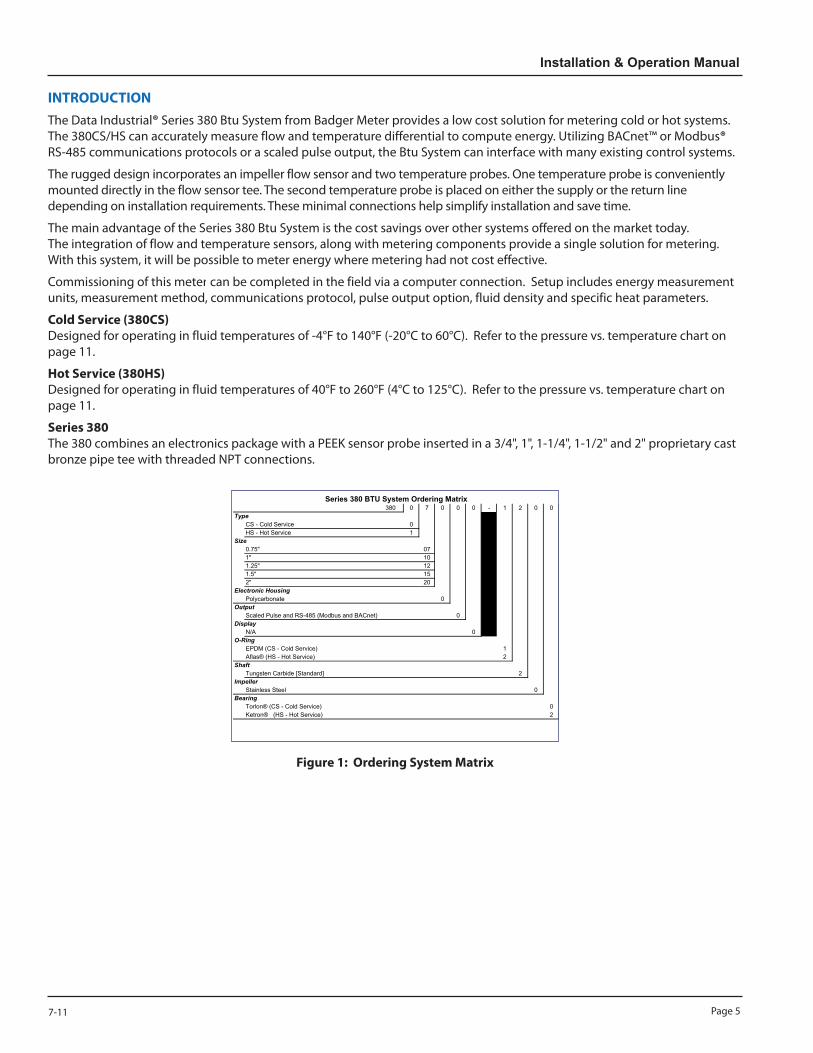
Series 380 The 380 combines an electronics package with a PEEK sensor probe inserted in a 3/4", 1", 1-1/4", 1-1/2" and 2" proprietary cast bronze pipe tee with threaded NPT connections.
380 0 7 0 0 0 - 1 2 0 0Type
CS - Cold Service 0HS - Hot Service 1
Size0.75" 071" 101.25" 121.5" 152" 20
Electronic HousingPolycarbonate 0
OutputScaled Pulse and RS-485 (Modbus and BACnet) 0
DisplayN/A 0
O-RingEPDM (CS - Cold Service) 1Aflas® (HS - Hot Service) 2
ShaftTungsten Carbide [Standard] 2
ImpellerStainless Steel 0
BearingTorlon® (CS - Cold Service) 0Ketron® (HS - Hot Service) 2
Cold Service Price3/4" 380007000-1200 395.00$
1" 380010000-1200 405.00$1 1/4" 380012000-1200 420.00$1 1/2" 380015000-1200 435.00$
2" 380020000-1200 475.00$Hot Service
3/4" 380107000-2202 405.00$1" 380110000-2202 420.00$
1 1/4" 380112000-2202 445.00$1 1/2" 380115000-2202 460.00$
2" 380120000-2202 500.00$
Series 380 BTU System Ordering Matrix
Figure 1: Ordering System Matrix
Page 6 7-11
Series 380 Impeller Btu System
MECHANICAL INSTALLATION
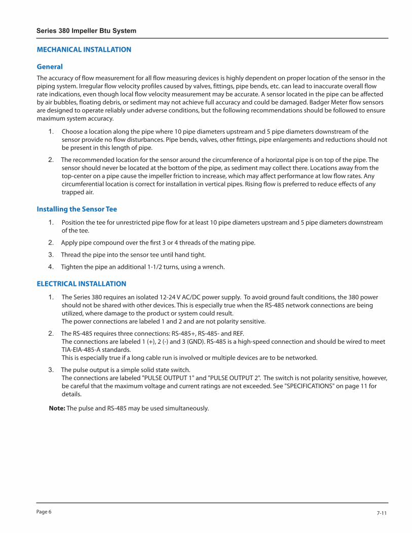
GeneralThe accuracy of flow measurement for all flow measuring devices is highly dependent on proper location of the sensor in the piping system. Irregular flow velocity profiles caused by valves, fittings, pipe bends, etc. can lead to inaccurate overall flow rate indications, even though local flow velocity measurement may be accurate. A sensor located in the pipe can be affected by air bubbles, floating debris, or sediment may not achieve full accuracy and could be damaged. Badger Meter flow sensors are designed to operate reliably under adverse conditions, but the following recommendations should be followed to ensure maximum system accuracy.
1. Choose a location along the pipe where 10 pipe diameters upstream and 5 pipe diameters downstream of the sensor provide no flow disturbances. Pipe bends, valves, other fittings, pipe enlargements and reductions should not be present in this length of pipe.
2. The recommended location for the sensor around the circumference of a horizontal pipe is on top of the pipe. The sensor should never be located at the bottom of the pipe, as sediment may collect there. Locations away from the top-center on a pipe cause the impeller friction to increase, which may affect performance at low flow rates. Any circumferential location is correct for installation in vertical pipes. Rising flow is preferred to reduce effects of any trapped air.
Installing the Sensor Tee
1. Position the tee for unrestricted pipe flow for at least 10 pipe diameters upstream and 5 pipe diameters downstream of the tee.
2. Apply pipe compound over the first 3 or 4 threads of the mating pipe.
3. Thread the pipe into the sensor tee until hand tight.
4. Tighten the pipe an additional 1-1/2 turns, using a wrench.
ELECTRICAL INSTALLATION
1. The Series 380 requires an isolated 12-24 V AC/DC power supply. To avoid ground fault conditions, the 380 power should not be shared with other devices. This is especially true when the RS-485 network connections are being utilized, where damage to the product or system could result. The power connections are labeled 1 and 2 and are not polarity sensitive.
2. The RS-485 requires three connections: RS-485+, RS-485- and REF. The connections are labeled 1 (+), 2 (-) and 3 (GND). RS-485 is a high-speed connection and should be wired to meet TIA-EIA-485-A standards. This is especially true if a long cable run is involved or multiple devices are to be networked.
3. The pulse output is a simple solid state switch. The connections are labeled "PULSE OUTPUT 1" and "PULSE OUTPUT 2". The switch is not polarity sensitive, however, be careful that the maximum voltage and current ratings are not exceeded. See "SPECIFICATIONS" on page 11 for details.
Note: The pulse and RS-485 may be used simultaneously.
Page 77-11
Installation & Operation Manual
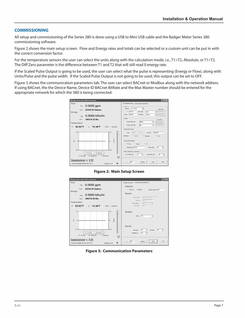
COMMISSIONINGAll setup and commissioning of the Series 380 is done using a USB to Mini USB cable and the Badger Meter Series 380 commissioning software.
Figure 2 shows the main setup screen. Flow and Energy rates and totals can be selected or a custom unit can be put in with the correct conversion factor.
For the temperature sensors the user can select the units along with the calculation mode, i.e., T1>T2, Absolute, or T1<T2. The Diff Zero parameter is the difference between T1 and T2 that will still read 0 energy rate.
If the Scaled Pulse Output is going to be used, the user can select what the pulse is representing (Energy or Flow), along with Units/Pulse and the pulse width. If the Scaled Pulse Output is not going to be used, this output can be set to OFF.
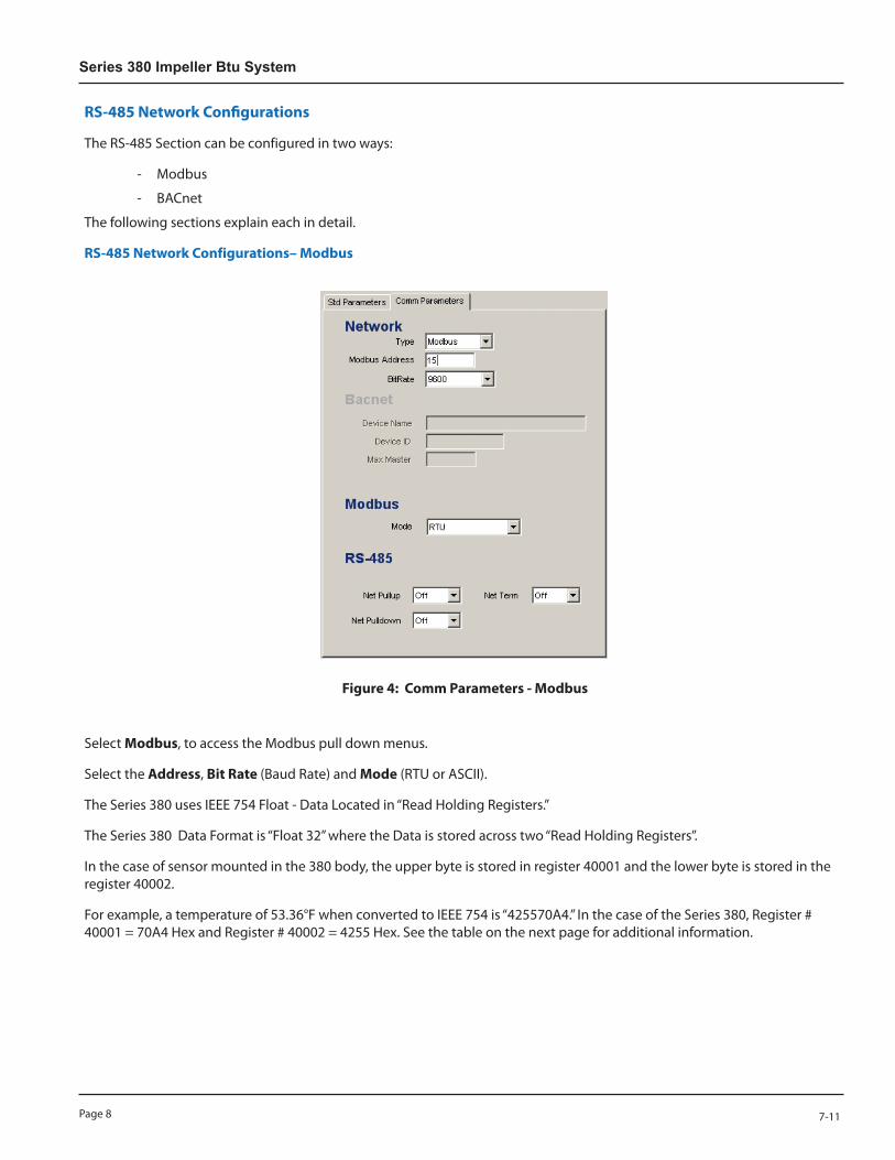
Figure 3 shows the communication parameters tab. The user can select BACnet or Modbus along with the network address. If using BACnet, the the Device Name, Device ID BACnet BitRate and the Max Master number should be entered for the appropriate network for which the 380 is being connected.
Figure 2: Main Setup Screen
Figure 3: Communication Parameters
Page 8 7-11
Series 380 Impeller Btu System
RS-485 Network Configurations
The RS-485 Section can be configured in two ways:
- Modbus
- BACnet
The following sections explain each in detail.
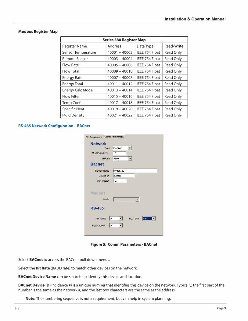
RS-485 Network Configurations– Modbus
Figure 4: Comm Parameters - Modbus
Select Modbus, to access the Modbus pull down menus.
Select the Address, Bit Rate (Baud Rate) and Mode (RTU or ASCII).
The Series 380 uses IEEE 754 Float - Data Located in “Read Holding Registers.”
The Series 380 Data Format is “Float 32” where the Data is stored across two “Read Holding Registers”.
In the case of sensor mounted in the 380 body, the upper byte is stored in register 40001 and the lower byte is stored in the register 40002.
For example, a temperature of 53.36°F when converted to IEEE 754 is “425570A4.” In the case of the Series 380, Register # 40001 = 70A4 Hex and Register # 40002 = 4255 Hex. See the table on the next page for additional information.
Page 97-11
Installation & Operation Manual
Modbus Register Map
Series 380 Register Map
Register Name Address Data Type Read/Write
Sensor Temperature 40001 + 40002 IEEE 754 Float Read Only
Remote Sensor 40003 + 40004 IEEE 754 Float Read Only
Flow Rate 40005 + 40006 IEEE 754 Float Read Only
Flow Total 40009 + 40010 IEEE 754 Float Read Only
Energy Rate 40007 + 40008 IEEE 754 Float Read Only
Energy Total 40011 + 40012 IEEE 754 Float Read Only
Energy Calc Mode 40013 + 40014 IEEE 754 Float Read Only
Flow Filter 40015 + 40016 IEEE 754 Float Read Only
Temp Coef 40017 + 40018 IEEE 754 Float Read Only
Specific Heat 40019 + 40020 IEEE 754 Float Read Only
Fluid Density 40021 + 40022 IEEE 754 Float Read Only
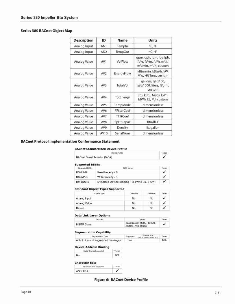
RS-485 Network Configuration – BACnet
Figure 5: Comm Parameters - BACnet
Select BACnet to access the BACnet pull down menus.
Select the Bit Rate (BAUD rate) to match other devices on the network.
BACnet Device Name can be set to help identify this device and location.
BACnet Device ID (Incidence #) is a unique number that identifies this device on the network. Typically, the first part of the number is the same as the network #, and the last two characters are the same as the address.
Note: The numbering sequence is not a requirement, but can help in system planning.
Page 10 7-11
Series 380 Impeller Btu System
Series 380 BACnet Object Map
Description ID Name UnitsAnalog Input AN1 TempIn ºC, ºF
Analog Input AN2 TempOut ºC, ºF
Analog Value AV1 VolFlowgpm, gph, lpm, lps, lph, ft3/s, ft3/m, ft3/h, m3/s, m3/min, m3/h, custom
Analog Value AV2 EnergyFlow kBtu/min, kBtu/h, kW, MW, HP, Tons, custom
Analog Value AV3 TotalVolgallons, galx100,
galx1000, liters, ft3, m3, custom
Analog Value AV4 TotEnergy Btu, kBtu, MBtu, kWh, MWh, kJ, MJ, custom
Analog Value AV5 TempMode dimensionless
Analog Value AV6 FFilterCoef dimensionless
Analog Value AV7 TFiltCoef dimensionless
Analog Value AV8 SpHtCapac Btu/lb-F
Analog Value AV9 Density lb/gallon
Analog Value AV10 SerialNum dimensionless
BACnet Protocol Implementation Conformance Statement
BMA Doc. x – 00x Page 1 of 1
BACnet Standardized Device Profile Device Profile Tested
BACnet Smart Actuator (B-SA) �
Supported BIBBs Supported BIBBs BIBB Name Tested
DS-RP-B ReadProperty - B � DS-WP-B WriteProperty - B � DM-DDB-B Dynamic Device Binding - B (Who-Is, I-Am) �
Standard Object Types Supported
Object Type Creatable Deletable Tested
Analog Input No No � Analog Value No No � Device No No �
Data Link Layer Options Data Link Options Tested
MS/TP Slave baud rates: 9600, 19200, 38400, 76800 bps �
Segmentation Capability Segmentation Type Supported Window Size
(MS/TP product limited to 1) Tested
Able to transmit segmented messages No N/A
Device Address Binding Static Binding Supported Tested
No N/A
Character Sets Character Sets supported Tested
ANSI X3.4 �
Figure 6: BACnet Device Profile
Page 117-11
Installation & Operation Manual
SPECIFICATIONSSensor Assembly: Housing: PEEK Impeller: 316SS Shaft: Tungsten Carbide CS Specific: Torlon® Bearing, EDPM O-Rings HS Specific: Ketron® Bearing, Aflas® O-Rings
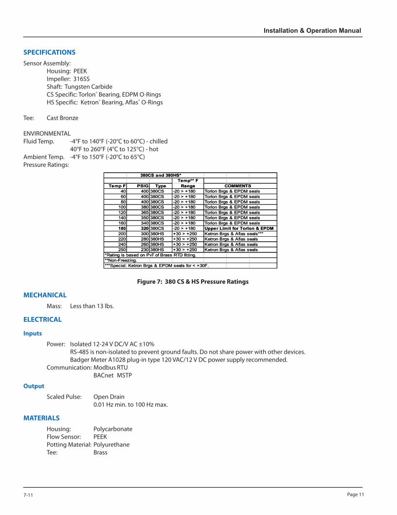
Tee: Cast Bronze ENVIRONMENTAL Fluid Temp. -4°F to 140°F (-20°C to 60°C) - chilled 40°F to 260°F (4°C to 125°C) - hot Ambient Temp. -4°F to 150°F (-20°C to 65°C) Pressure Ratings:
Badger Data Industrial Series 380 BTU Systems
SpecificationsMECHANICAL
Sensor Assembly Mass < 15lbHouseing: PEEKImpeller: 316SS ELECTRICALShaft: Tungston Carbide InputsCS Specific: Torlon Bearing, EDPM O‐Rings Power 12‐35VDCHS Specific: Ketron Bearing, Aflas O‐Rings 9‐28VAC rms
Communication ModbusTee BACnet
Cast Bronze OutputScaled Pulse Open Drain
Temperature Rating For Wetted MaterialsCS: ‐20F to 180F MATERIALSHS: 30F to 250F Housing Polycarbonate
Flow Sensor PEEKAmbient Temperature Rating Potting Material Polyurethane
‐20C to 65C Tee Brass
Pressure Ratings Sensor Body SizesTee Sizes 0.75", 1", 1.25", 1.5", and 2"
Recommended Design Flow Range1 to 15 FPS
380CS and 380HS*Temp** F
Temp F PSIG Type Range COMMENTS40 400 380CS -20 > +180 Torlon Brgs & EPDM seals60 400 380CS -20 > +180 Torlon Brgs & EPDM seals80 400 380CS -20 > +180 Torlon Brgs & EPDM seals
100 380 380CS -20 > +180 Torlon Brgs & EPDM seals120 365 380CS -20 > +180 Torlon Brgs & EPDM seals140 350 380CS -20 > +180 Torlon Brgs & EPDM seals160 340 380CS -20 > +180 Torlon Brgs & EPDM seals180 320 380CS -20 > +180 Upper Limit for Torlon & EPDM200 300 380HS +30 > +250 Ketron Brgs & Aflas seals***220 280 380HS +30 > +250 Ketron Brgs & Aflas seals240 260 380HS +30 > +250 Ketron Brgs & Aflas seals250 230 380HS +30 > +250 Ketron Brgs & Aflas seals
*Rating is based on PvT of Brass RTD fitting.**Non-Freezing.***Special: Ketron Brgs & EPDM seals for < +30F.
AccuracyFlow Calculation: ±1% of RateTemperature Calculation: ±1% BTU Calculation: ±1%
Output Pulse Width10, 50, 150, 200, or 250mS
Put Image of Dimentional Drawing here
380CS and 380HS*Temp** F
Temp F PSIG Type Range COMMENTS40 400 380CS -20 > +180 Torlon Brgs & EPDM seals60 400 380CS -20 > +180 Torlon Brgs & EPDM seals80 400 380CS -20 > +180 Torlon Brgs & EPDM seals
100 380 380CS -20 > +180 Torlon Brgs & EPDM seals120 365 380CS -20 > +180 Torlon Brgs & EPDM seals140 350 380CS -20 > +180 Torlon Brgs & EPDM seals160 340 380CS -20 > +180 Torlon Brgs & EPDM seals180 320 380CS -20 > +180 Upper Limit for Torlon & EPDM200 300 380HS +30 > +250 Ketron Brgs & Aflas seals***220 280 380HS +30 > +250 Ketron Brgs & Aflas seals240 260 380HS +30 > +250 Ketron Brgs & Aflas seals250 230 380HS +30 > +250 Ketron Brgs & Aflas seals
*Rating is based on PvT of Brass RTD fitting.**Non-Freezing.***Special: Ketron Brgs & EPDM seals for < +30F.
Figure 7: 380 CS & HS Pressure Ratings
MECHANICAL Mass: Less than 13 lbs.
ELECTRICAL
Inputs
Power: Isolated 12-24 V DC/V AC ±10% RS-485 is non-isolated to prevent ground faults. Do not share power with other devices. Badger Meter A1028 plug-in type 120 VAC/12 V DC power supply recommended. Communication: Modbus RTU BACnet MSTP
Output
Scaled Pulse: Open Drain 0.01 Hz min. to 100 Hz max.
MATERIALS Housing: Polycarbonate Flow Sensor: PEEK Potting Material: Polyurethane Tee: Brass
Page 12 7-11
Series 380 Impeller Btu System
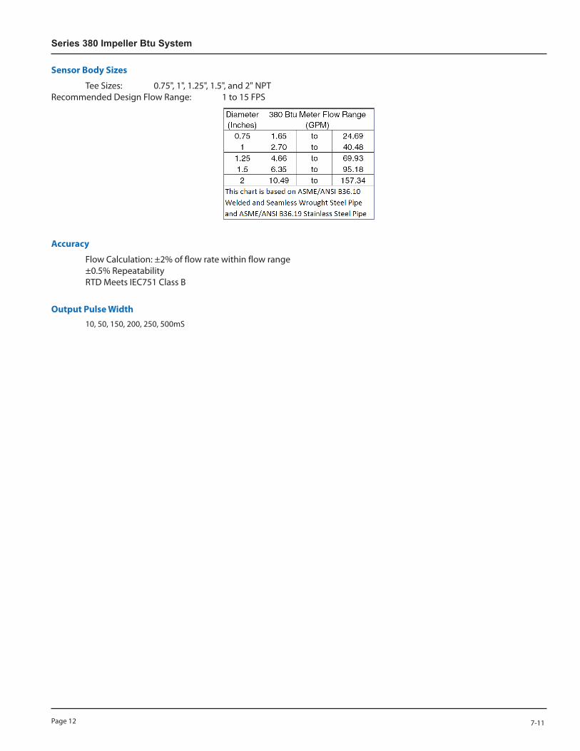
Sensor Body Sizes
Tee Sizes: 0.75", 1", 1.25", 1.5", and 2" NPT Recommended Design Flow Range: 1 to 15 FPS
Accuracy
Flow Calculation: ±2% of flow rate within flow range ±0.5% Repeatability RTD Meets IEC751 Class B
Output Pulse Width 10, 50, 150, 200, 250, 500mS

Page 137-11
Installation & Operation Manual
Intentional Blank Page

Data Industrial is a registered trademark of Badger Meter, Inc.
Other trademarks appearing in this document are the property of their respective entities.
Copyright 2011, Badger Meter, Inc. All rights reserved.
Due to continuous research, product improvements and enhancements, Badger Meter reserves the right to change product or system specifications without notice, except to the extent an outstanding contractual obligation exists.
Badger Meter | P.O. Box 245036, Milwaukee, Wisconsin 53224-9536 800-876-3837 | [email protected] | www.badgermeter.com
Please see our website at www.badgermeter.comfor specific contacts.


