• Energy Efficient • Easy to Install • Extended Service Life Horizontal Direct Drive Blower Coils INSTALLATION, OPERATIONS AND MAINTENANCE MANUAL • Engineered to save our customers money • Eliminate the belt and pulleys • Energy efficient EC Motor • Improve indoor air quality • Experience quieter operations • Reduce costs • Nominal CFM range of 600 to 3,000 CFM
Transcript
• Energy Efficient • Easy to Install• Extended Service Life
Horizontal Direct Drive Blower CoilsINSTALLATION, OPERATIONS AND MAINTENANCE MANUAL
• Engineered to save our customers money• Eliminate the belt and pulleys • Energy efficient EC Motor• Improve indoor air quality• Experience quieter operations• Reduce costs• Nominal CFM range of 600 to 3,000 CFM
International Environmental Corporation (IEC) works continually to improve its products. As a result, the design and specifications of each product may be changed without notice and may not be as described herein. Please contact IEC for information regarding current design and product specifications. Statements and other information contained herein are not express warranties and do not form the basis of any bargain between the parties but are merely IEC’s opinion or commendation of its products. Manufacturer’s standard limited warranty applies.
3 Preface
4 Unpacking and Inspection
5 Installation – Mounting
6 Operating weight
7 Mixing Box Installation
8 Piping
8 -9 Electrical Connections, ductwork
9 Start-up
12 Service, maintenance
14-15 Filters
16-17 Piping connection location
18-19 HDY Physical data/submittal drawings
20 Electric heat data
21-32 Typical wiring diagram examples
33 Equipment Installation and Start-Up Check List
34 Replacement parts
35 Terms and conditions
Horizontal Direct Drive Blower CoilsINSTALLATION, OPERATION AND MAINTENANCE MANUAL
2
SECTION 1 – IntroductionInternational Environmental Corporation (IEC) fan coil units represent a prudent investment, offering trouble-free operation and long service with proper installation, operation, and regular maintenance. The equipment covered by this manual is available with a variety of options and accessories. Always consult the approved unit submittals, order acknowledgement, and other manuals for specific details on unit options and accessories. Always follow proper procedures related to safety, handling, installation, operation, and servicing of mechanical equipment as the manufacturer assumes no responsibility for personal injury or property damage resulting from improper or unsafe practices during the handling, installation, service, or operation of any equipment.
SafetyIEC equipment is initially protected under the manufacturer’s standard warranty; however, this warranty is provided under the condition that the steps outlined in this manual for initial inspection, proper installation, commissioning, regular periodic maintenance, and everyday operation of the equipment be followed in detail. This manual should be fully reviewed and understood in advance of initial installation, startup, and any maintenance. Should any questions arise, please contact your local Sales Representative or the factory BEFORE proceeding.
WARNING: NO ATTEMPT SHOULD BE MADE TO HANDLE, INSTALL, OR SERVICE ANY UNIT WITHOUT FOLLOWING SAFE PRACTICES REGARDING MECHANICAL EQUIPMENT.
Always use proper equipment support. Secure all pre-installation supports.
CAUTION: Disconnect all power prior to any installation or service (unit may use more than one power source; ensure all are disconnected)
Power to remote mounted control devices may not be supplied by unit.
Install approved Lock-Out/Tag-Out protection devices on ALL incoming power sources to equipment being
installed or serviced prior to beginning any work. Always verify all incoming power sources are de-energized using an electrical multi-meter.
CAUTION: Never wear bulky or loose fitting clothing when working on any mechanical equipment. Gloves should always be worn for
protection against sharp sheet metal edges, heat, and other possible injuries. Safety glasses or goggles should always be worn, especially when drilling, cutting, or working with refrigerants, lubricants or cleaning chemicals.
WARNING: Never pressurize any equipment beyond specified test pressures listed on the unit rating plate. Always pressure test with an inert fluid or gas such as clear water or dry nitrogen to avoid possible damage or injury in the event of a leak or component failure during testing.
CAUTION: Always protect adjacent flammable material when welding or soldering. Use a suitable heat shield material to contain sparks or
drops of solder. Have a fire extinguisher readily available.
CAUTION: Always protect chilled and hot water valve bodies, strainers, ball valves, and other flow control related devices from heat caused
by soldering or brazing processes.
Safety should always be first priority when handling, installing, operating or servicing mechanical equipment. Always follow all safety codes, procedures and protocols.
Consult applicable local building codes and National Electrical Codes (NEC) for special requirements. Be alert to safety information: symbols, words such as DANGER, WARNING and CAUTION.
Improper installation, adjustment, service, maintenance, or use can cause explosion, fire, electrical shock, or other conditions, which may result in personal injury or property damage. This product must be installed only by personnel with the training, experience, skills, and applicable licensing that makes him/her “a qualified professional HVACR installer".
3
Horizontal Direct Drive Blower Coils INSTALLATION, OPERATION AND MAINTENANCE MANUAL
SECTION 2 – Pre-Installation Unpacking and InspectionAll units are carefully inspected at the factory throughout the manufacturing process under a strict detailed quality assurance program. All major components and sub-assemblies are carefully tested for proper operation and verified for full compliance with factory standards. Operational testing of some customer-furnished components such as DDC controls, pneumatic control valves and switches may be a possible exception.
Each unit is carefully packaged for shipment to prevent damage during normal transit and handling. Equipment should always be stored in a dry and covered place, and in proper orientation marked on the carton.
All shipments are made F.O.B. ex-factory and it is the responsibility of the receiving party to inspect the equipment upon arrival. Any obvious damage to the packaging and/or its contents should be recorded on the bill of lading and a claim filed with the freight carrier.
After inspecting condition of packaging exterior, carefully remove each unit from the carton and inspect for hidden damage. Any hidden damage or missing components should be recorded and immediately reported to the carrier and a claim filed. In the event a claim for shipping damage is filed, the unit, shipping carton, and all packing must be retained for physical inspection by the freight carrier. All equipment must be stored in the factory shipping carton with internal packing in place until installation.
At time of receipt, equipment type and arrangement must be verified by review of order documents. Should any discrepancy be found, the local Sales Representative must be notified immediately so that proper action may be taken.
Should any questions arise concerning field warranty repairs, factory must be notified BEFORE any corrective action is taken.
When repairs or alterations can be accomplished locally, the factory must be fully informed of the extent and expected cost of repairs before work begins. When factory operations are required, the factory must be contacted for authorization to return equipment and a Return Authorization Number will be issued.
Unauthorized return shipments of equipment and shipments not marked with an authorization number will be refused. In addition, any claims for unauthorized expenses will not be accepted by the manufacturer.
Prepare Job site for Unit InstallationTo save time and to reduce the possibility of costly errors, set up a complete sample installation in a typical room at the job site. Check all the critical dimensions such as field piping, wiring, and duct connection to ensure they agree with job requirements. Refer to job drawings and product dimension drawings as required (See Figures 16-17 for sample drawings). Instruct all trades in their part of the installation. Should any discrepancies be discovered, contact your local representative before continuing with unit installations.
Identify and Prepare UnitsFor each unit, confirm incoming and control power requirements match available power source. Refer to unit nameplate and wiring diagram.
1. Review all tags on unit to determine if shipping screws are to be removed. Remove screws as directed.
2. Rotate fan wheel by hand to ensure that fan is unrestricted and can rotate freely. Inspect for shipping damage and fan obstructions. Adjust blower wheel as required.
Protect Units from DamageCare must be taken to assure that no force or pressure is applied to the coil, piping or drain stub-outs during handling. The equipment covered in this manual IS NOT suitable for outdoor installations. The equipment is never to be stored or installed where it may be subjected to a hostile environment such as rain, snow, or extreme temperatures.
Before, during, and after installation, take specific caution to prevent foreign material such as paint, plaster, and drywall dust from being deposited in the drain pan, on the motor or blower wheels and cooling/heating coils. Failure to do so may have serious adverse effects on unit operation, and in the case of motor and blower assembly, may result in immediate or premature failure and voiding all manufacturers’ warranties. Some units and/or job conditions may require some form of temporary covering
Horizontal Direct Drive Blower CoilsINSTALLATION, OPERATION AND MAINTENANCE MANUAL
4
during construction. While the manufacturer is not involved in the design and selection of support methods and components, it shall be noted that unacceptable system operating characteristics and/or performance may result from improper or inadequate unit structural support. After mounting, the unit is then ready for the various service connections such as water, drain and electrical. Verify which proper type of services are actually provided to the unit. On units requiring chilled water and/or hot water, verify proper line size and water supply availability.
SECTION 3 – Installation Horizontal Units (Standard)
Place Units In Position.
Install mixing box when ordered with unit. Follow mixing box installation instructions outlined in the next section. The horizontal blower coil units have 5/8" knockouts in each corner of the top and bottom panels for 1/2" all thread (not supplied with unit) to pass through (see Figure 2). Always support the unit at the base until mounting is complete.
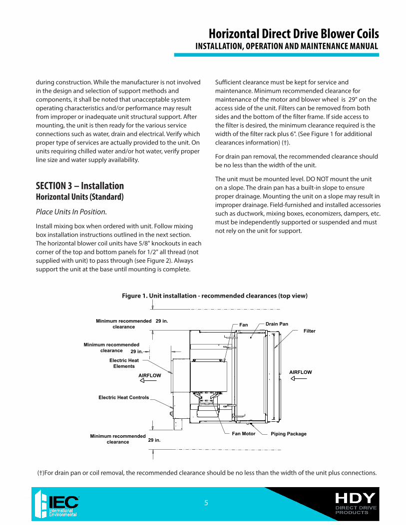
Sufficient clearance must be kept for service and maintenance. Minimum recommended clearance for maintenance of the motor and blower wheel is 29" on the access side of the unit. Filters can be removed from both sides and the bottom of the filter frame. If side access to the filter is desired, the minimum clearance required is the width of the filter rack plus 6". (See Figure 1 for additional clearances information) (†).
For drain pan removal, the recommended clearance should be no less than the width of the unit.
The unit must be mounted level. DO NOT mount the unit on a slope. The drain pan has a built-in slope to ensure proper drainage. Mounting the unit on a slope may result in improper drainage. Field-furnished and installed accessories such as ductwork, mixing boxes, economizers, dampers, etc. must be independently supported or suspended and must not rely on the unit for support.
Minimum recommended clearance
Minimum recommended clearance
Electric Heat Controls
AIRFLOW AIRFLOW
FilterDrain Pan
Electric Heat Elements
29 in.
Minimum recommended clearance
29 in.
29 in.Fan Motor Piping Package
Fan
Figure 1. Unit installation - recommended clearances (top view)
(†)For drain pan or coil removal, the recommended clearance should be no less than the width of the unit plus connections.
5
Horizontal Direct Drive Blower Coils INSTALLATION, OPERATION AND MAINTENANCE MANUAL
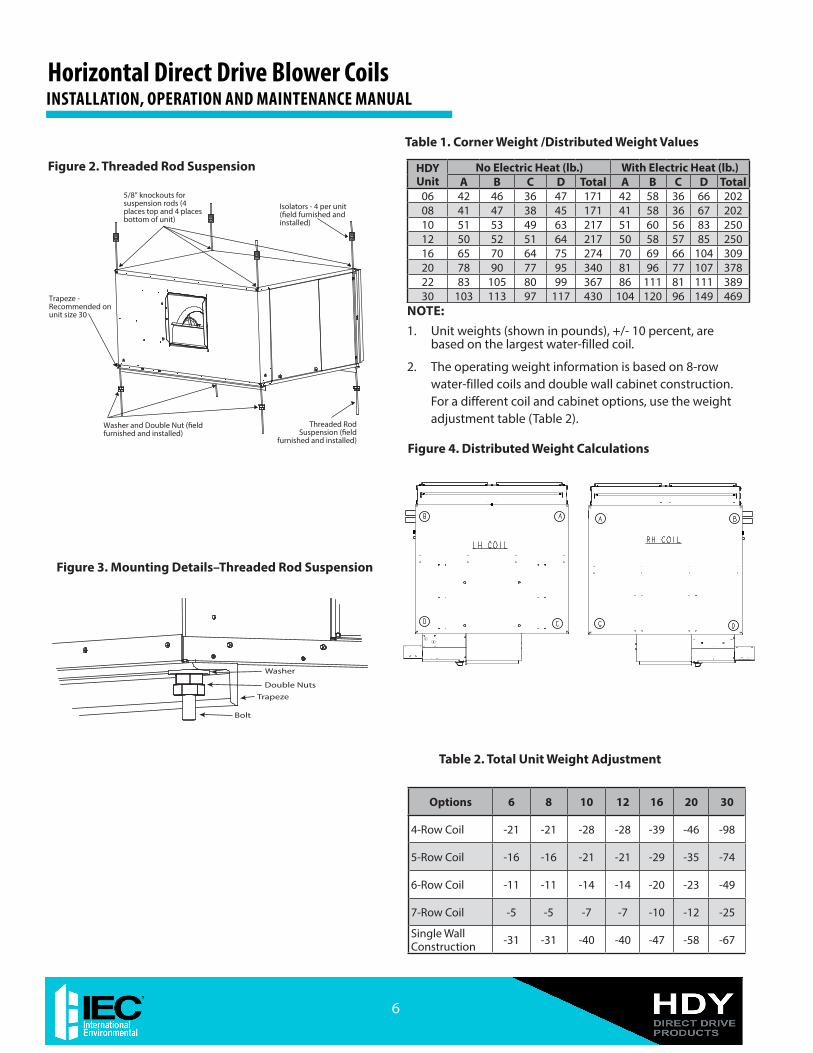
Washer
Double Nuts
Trapeze
Bolt
Figure 3. Mounting Details–Threaded Rod Suspension
Figure 2. Threaded Rod Suspension
Isolators - 4 per unit (�eld furnished and installed)
Washer and Double Nut (�eld furnished and installed)
5/8” knockouts forsuspension rods (4 places top and 4 places bottom of unit)
Threaded Rod Suspension (�eld
furnished and installed)
Trapeze - Recommended on unit size 30
HDY Unit
No Electric Heat (lb.) With Electric Heat (lb.)A B C D Total A B C D Total
Single Wall Construction -31 -31 -40 -40 -47 -58 -67
Figure 4. Distributed Weight Calculations
Table 2. Total Unit Weight Adjustment
Table 1. Corner Weight /Distributed Weight Values
NOTE: 1. Unit weights (shown in pounds), +/- 10 percent, are
based on the largest water-filled coil.
2. The operating weight information is based on 8-row water-filled coils and double wall cabinet construction. For a different coil and cabinet options, use the weight adjustment table (Table 2).
Horizontal Direct Drive Blower CoilsINSTALLATION, OPERATION AND MAINTENANCE MANUAL
6
Figure 7. HDY with Mixing BoxMixing Box Installation
1. Mixing boxes are pre-assembled from the factory for ease of installation. A linkage kit consisting of two crank arms, 2 swivels, and either a 25" (sizes 06-16) or a 34" (sizes 20-30) length of 5/16" rod is provided for field installation of an actuator. Mixing boxes are only compatible with side/bottom access-style filter frames (non-magnetic latching doors).
2. Assemble the base rails (provided with mixing box). All hardware required for assembly is included and the base rails are letter coded for ease of assembly, as shown in Figure 6.
3. Place HDY unit on the base rails. Unit is mounted flush to the outer edge of the end base rail at the aligning unit mounting holes indicated (as shown in Figure 7, Detail A). It may be necessary to remove factory installed sheet metal screws to enable access to all mounting holes and to ensure proper fitment. Do not remove screws unless necessary. Secure base rail to unit with supplied #8x1/2" sheet metal screws, two per side.
Figure 5. Base Rails
Figure 6. Letter Coding on Base Rail Parts DETAIL A
SEE DETAIL A
7
Horizontal Direct Drive Blower Coils INSTALLATION, OPERATION AND MAINTENANCE MANUAL
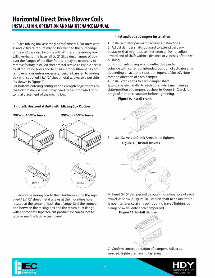
Figure 8. Horizontal Units with Mixing Box Option
DETAIL A DETAIL B
SEE DETAIL BSEE DETAIL A
4. Place mixing box assembly onto frame rail. For units with 1” and 2” filters, mount mixing box flush to the outer edge of the end base rail, for units with 4" filters, the mixing box will over-hang the base rail by 2". Slide duct flanges of box over the flanges of the filter frame. It may be necessary to remove factory installed sheet metal screws to enable access to all mounting holes and to ensure proper fitment. Do not remove screws unless necessary. Secure base rail to mixing box with supplied #8x1/2" sheet metal screws, two per side (as shown in Figure 8).For bottom-entering configurations, length adjustments to the bottom damper shaft may need to be completed prior to final placement of the mixing box.
5. Secure the mixing box to the filter frame using the sup-plied #8x1/2" sheet metal screws at the mounting hole located at the center of each duct flange. Seal the connec-tion between the mixing box and the return duct flange with appropriate tape/sealant product. Be careful not to tape or seal the filter access panel.
1. Install actuator per manufacturer's instructions. 2. Adjust damper shafts outward to extend past any obstacles that might cause interference. Do not adjust inward end of shaft within a distance of 2 inches of bronze bushing.3. Position inlet damper and outlet damper to coincide with current or intended position of actuator arm, depending on actuator's position (opened/closed). Note rotation direction of each damper. 4. Install crank arms to each damper shaft approximately parallel to each other while maintaining state/position of dampers, as show in Figure 9. Check for range of motion clearances before tightening.
Figure 9. Install crank.
5. Install Swivels to Crank Arms, hand tighten.
6. Insert 5/16" damper rod through mounting hole of each swivel, as show in Figure 10. Position shaft to ensure there is not interference at any point during travel. Tighten rod clamp of swivel onto each damper rod.
Figure 11. Install damper
7. Confirm correct operation of dampers. Adjust as needed. Tighten remaining fasteners.
Figure 10. Install swivels
SEE DETAIL A
DETAIL A
Inlet and Outlet Dampers Installation
HDY with 2" Filter frame HDY with 4" Filter frame
Horizontal Direct Drive Blower CoilsINSTALLATION, OPERATION AND MAINTENANCE MANUAL
8
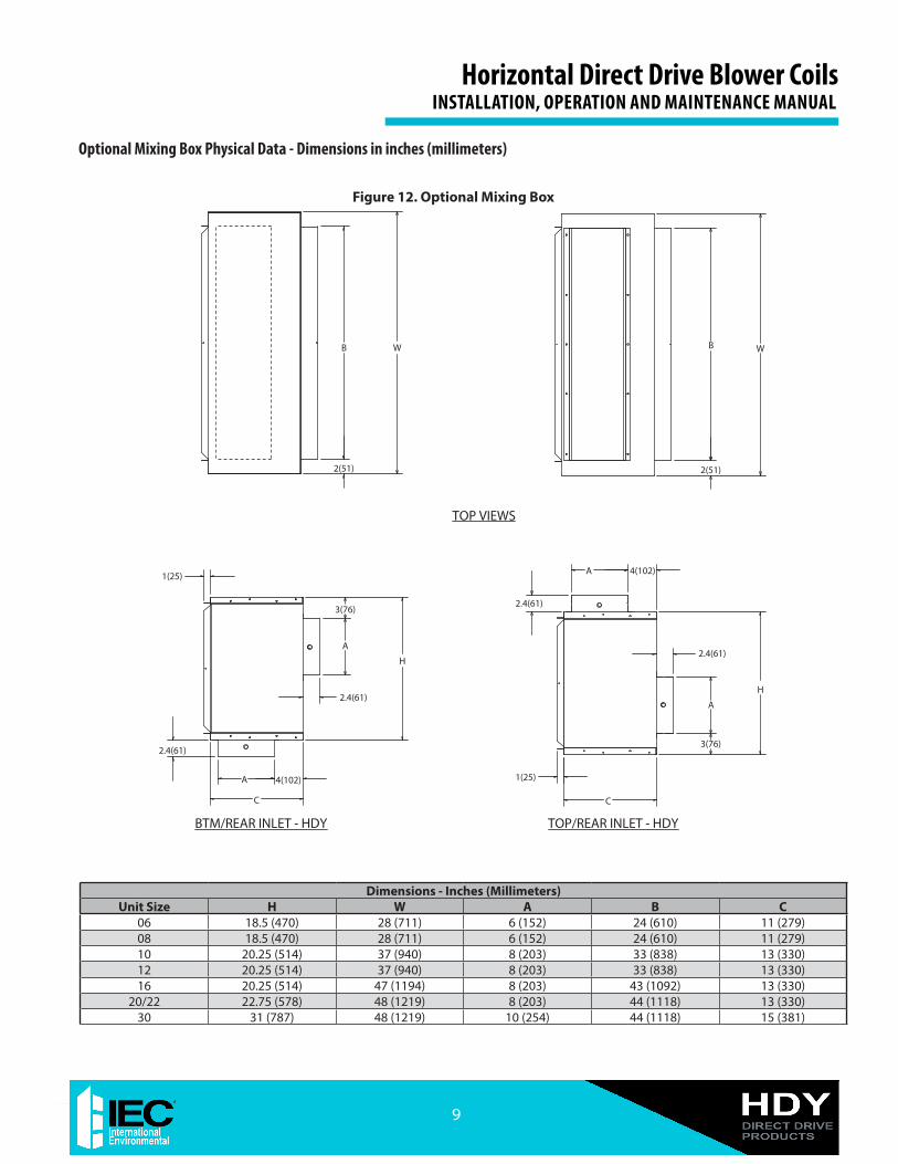
Dimensions - Inches (Millimeters)Unit Size H W A B C
Optional Mixing Box Physical Data - Dimensions in inches (millimeters)
3(76)
A
C
2.4(61)
4(102)
H
2.4(61)
3(76)
1(25)
2(51)2(51)
WB
TOP VIEWS
BTM/REAR INLET - HDY TOP/REAR INLET - HDY
RIGHT HAND SIDE VIEWS
W
4(102)
2.4(61)
C
1(25)
H
A
A
B
A
2.4(61)
Figure 12. Optional Mixing Box
9
Horizontal Direct Drive Blower Coils INSTALLATION, OPERATION AND MAINTENANCE MANUAL
Cooling/Heating Pipe ConnectionsCAUTION: Residue and loose particles resulting from manufacturing and field piping techniques
such as joint compounds, soldering flux, and metal shavings may be present in the unit and the piping system. Ensure system cleanliness when connecting to solar, domestic or potable water systems.
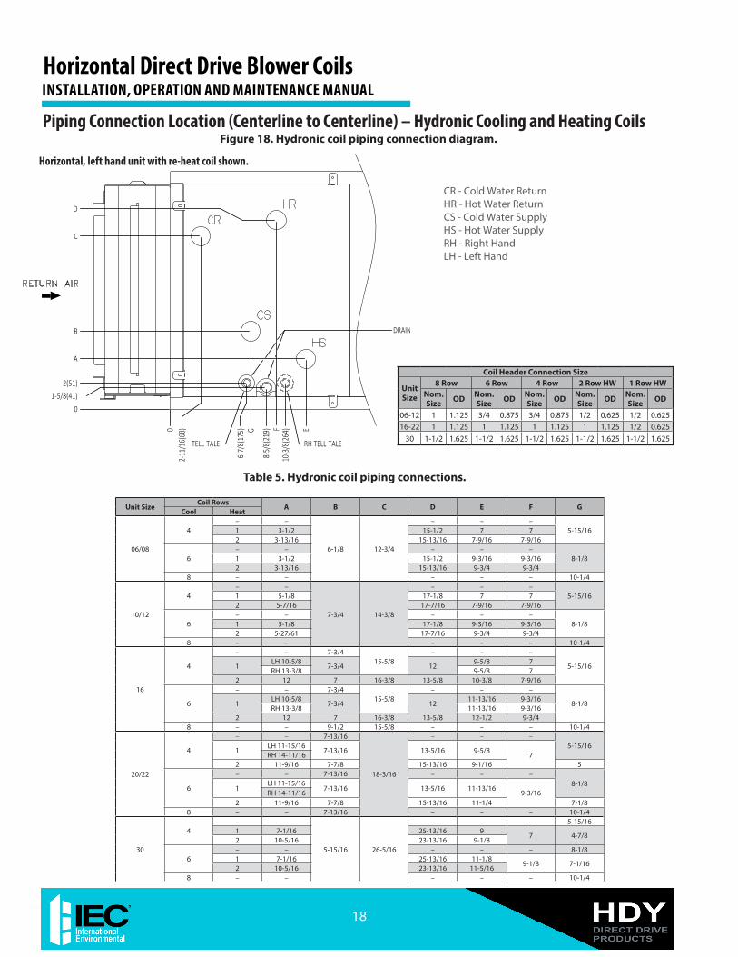
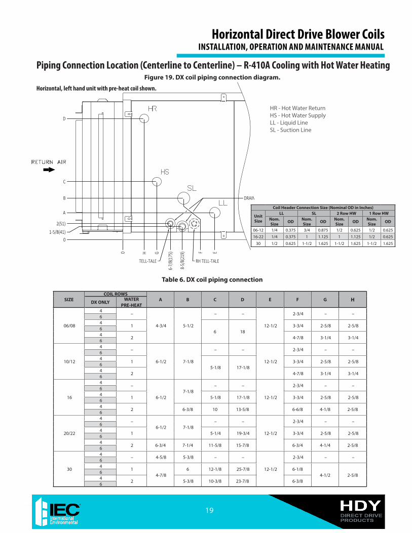
Thoroughly review submittals and product literature detailing unit operation, controls, and connections BEFORE beginning the connection of the various cooling and/or heating mediums to the unit. The supply and return connections are marked with a “HS/CS” meaning Hot/Cold water Supply or inlet and “HR/CR” meaning Hot/Cold water Return or outlet indicating fluid flow direction into and from the coil. Refer to Figures 18 and 19 for details and DX coils marking and piping locations.
Leak TestingAfter securing the connections, test the system for any leaks. Always test hydronic systems with water as some components are not designed to be inert gas pressurized.
Field pressure testing for leaks should not exceed 300 psi for hydronic coil and valve package components. Consult factory if higher limits are required.
CAUTION: Protect all water coils from freezing after initial filling with water. Even if the system
is drained, unit coils may still hold enough water to cause damage when exposed to temperatures below freezing.
Refrigerant Coil TestingTest refrigerant systems with dry nitrogen rather than air to prevent the introduction of moisture into the system. In the event that leaking or defective components are discovered, notify the Sales Representative BEFORE any repairs are attempted. All leaks must be repaired before proceeding with the installation. In combination units with refrigerant and water coils, freeze protection device should be field-provided and installed. External equaliser should be installed by others.
Piping InsulationAfter system integrity has been established, insulate the piping in accordance with the project specifications. This is the responsibility of the installing or insulation contractor.
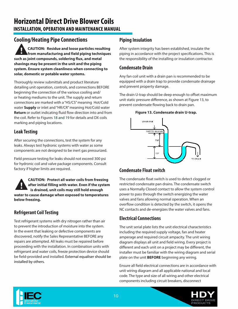
Condensate DrainAny fan coil unit with a drain pan is recommended to be equipped with a drain trap to provide condensate drainage and prevent property damage.
The drain U-trap should be deep enough to offset maximum unit static pressure difference, as shown at Figure 13, to prevent condensate flowing back to drain pan.
Condensate Float switchThe condensate float switch is used to detect clogged or restricted condensate pan drains. The condensate switch uses a Normally Closed contact to allow the system control power to pass through the switch energizing the water valves and fans allowing normal operation. When an overflow condition is detected by the switch, it opens the NC contacts and de-energizes the water valves and fans.
Electrical ConnectionsThe unit serial plate lists the unit electrical characteristics including the required supply voltage, fan and heater amperage and required circuit ampacity. The unit wiring diagram displays all unit and field wiring. Every project is different and each unit on a project may be different, the installer must be familiar with the wiring diagram and serial plate on the unit BEFORE beginning any wiring.
Ensure all field electrical connections are in accordance with unit wiring diagram and all applicable national and local code. The type and size of all wiring and other electrical components including circuit breakers, disconnect
Figure 13. Condensate drain U-trap.
reconnection, flooding of the
Horizontal Direct Drive Blower CoilsINSTALLATION, OPERATION AND MAINTENANCE MANUAL
10
switches, etc. shall be determined by the individual job requirements. Verify conductor size is suitable for the distance to the equipment connection and will support the equipment electrical load. All installations including field wiring shall be made in compliance with all governing codes and ordinances. Compliance with all codes is the responsibility of the installing contractor.
All components furnished for field installation by either the factory or the controls contractor shall be located and checked for proper function and compatibility. Inspect all internal components for shipping damage. Inspect all electrical connections within the unit control box and accessories and tighten if necessary.
NOTE: All field wiring must be in accordance with governing codes and ordinances. Any modification of unit wiring without factory authorization will invalidate all factory warranties and nullify any agency listings. The manufacturer assumes no responsibility for any damages and/or injuries resulting from improper field installation and/or wiring.
Cabinet/Control Box Maintenance Light
The optional Service Light provides a source of illumination in the main unit cabinet and the control box during routine maintenance and troubleshooting in the dark ceiling spaces. Light turns "ON" when access panel or control box door is open, but unit is not powered. (See Figure 16).
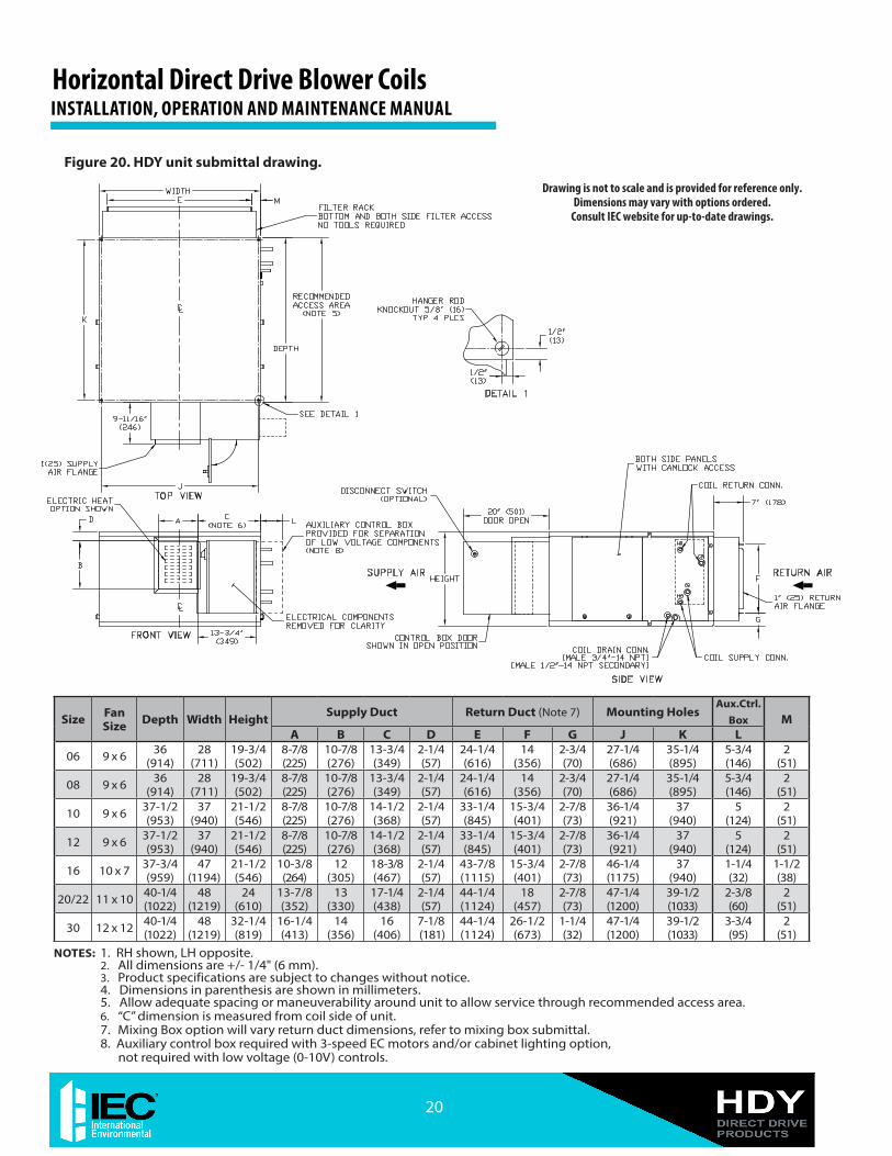
Connecting DuctworkAll ductwork shall be installed in accordance with the project plans and specifications. See Figure 20 and 21 for supply and return duct flanges location and dimensions.
NOTE: When installing units that attach to branch duct piping, use industry approved duct standards and configuration such as those published by Air Conditioning Contractors of America or American Society of Heating, Refrigeration and Air Conditioning Engineers. The standards provide necessary information on sizing, layout and installing supply and return air duct systems.
Flexible duct connections should be used on all air handling equipment. All ductwork and insulation shall be installed to allow proper access to all components for service and repair such as filters, motor/blower assemblies, etc.
Make Final Preparations
1 Power unit(s) off (open unit electrical disconnect) and install lockout tags on all power supplies to the unit.
2. Install field-supplied thermostats and perform all other final wiring needed. Ensure all electrical connections are secure.
3. Perform final visual inspection. All equipment, ductwork, and piping should be inspected to verify all systems are complete and properly installed and mounted, and that no debris or foreign articles are left in the unit(s). Clean dirt, dust, and other construction debris from unit interior. Assess fan wheel and housing and clean if necessary.
4. Verify drain line is properly and securely positioned and that the line is clear. Pour water into drain to verify operation.
5. Rotate fan wheel by hand to be sure it is free and does not rub housing.
6. Install the filter into the filter frame. If field-supplied filters are used, verify filter size (see Table 4).
7. Ensure all panels and filters are installed before checking fan operation. Turn on power to the unit.
8. Inspect the fan and motor operation.
SECTION 4 – StartupBefore beginning any startup operation, the startup personnel shall familiarize themselves with the unit, options and accessories, and control sequence to understand the proper system operation. All personnel shall have a good working knowledge of general startup procedures and have the appropriate startup and balancing guides available for consultation.
The building must be completely finished including doors, windows, and insulation. All internal walls and doors should be installed. In some cases, the interior decorations and furniture may influence overall system performance. The entire building should be as complete as possible before beginning any system balancing.
Cooling/Heating SystemPrior to the water system startup and balancing, flush the chilled/hot water systems to clean out dirt and debris which may have collected in the piping during construction. During this procedure, all unit service valves must be in the closed position to prevent foreign matter from entering the unit and clogging the valves and metering devices. Strainers shall be installed in the piping mains to prevent such material from entering units during normal operation.
11
Horizontal Direct Drive Blower Coils INSTALLATION, OPERATION AND MAINTENANCE MANUAL
During system filling, air venting from the unit is accomplished by the use of the standard, manual air vent fitting, or the optional, automatic air vent fitting installed on the coil ( Figure 14). Manual air vents are basic schrader valves that could be accessed from the coil side of the unit and are located between the coil header and end sheet. To vent the air from the coil, depress the valve until the air has vented the coil. When water begins to escape through the valve, release the valve.
Automatic air vents may be unscrewed one turn counterclockwise to speed initial venting, but should be screwed in for automatic venting after startup operations.
Figure 14. Air vents.
Manual Air Vent
Automatic Air Vent
CAUTION: The air vent provided on the unit is not intended to replace the main system air vents and may not release air trapped in other
parts of the system. Independently inspect the entire system for potential air traps and vent those areas as required. In addition, some systems may require repeated venting over a period of time to properly eliminate air from the system.
Air Balance SystemAll ductwork must be complete and connected. All filters and access doors and panels must be properly installed to establish actual system operating conditions BEFORE beginning air balancing operations.
Each individual unit and the attached ductwork is a unique system with its own operating characteristics. For this reason, air balancing is normally done by balance specialists who are familiar with all procedures required to properly establish air distribution and fan-system operating conditions. These procedures shall not be attempted by unqualified personnel.
After proper system operation is established, the actual unit air delivery and the actual fan motor amperage draw for each unit should be recorded in a convenient place for future reference.
Electronically Commutated Motor (ECM).
All HDY units are equipped with Electronically Commu-tated Motors (ECM) - constant speed brushless DC, which are easily adjustable in the field for desired performance. Motors are pre-programmed for constant speed mode.1/2 HP and 1 HP motors have an integrated control module with overload and short circuit protection.1-1/2 HP and 3 HP motors have a remote mounted control module with overload and short circuit protection. The control module is mounted in the cabinet interior.
Control Board adjustment.
Adjusting the Low, Medium and High potentiometer requires the use of multimeter capable of measuring 0~10 VDC.
CAUTION: Only trained and qualified individuals should attempt to adjust or service components on any energized electrical equipment. Failure to follow established safety rules and guidelines could result in serious injury or death.
Unit must be powered to perform the following procedure. Set the electrical multimeter to VDC (Volts Direct Current).Attach black negative (-) lead of meter to the terminal labeled “L2” (shown above the potentiometers).Attach the RED positive (+) lead of the meter to the terminal labeled “L1” and confirm that there is approximately 5~10 VDC present.
PotentiometerLow, Med, High CFM adjust
When HDY unit is shipped from the factory with motor control board (which has Hi, Med and Low airflow settings), it is pre-programmed at the factory to “High” speed and delivers the airflow and cooling/heating capacity specified at the time of order, while Medium and Low Speeds are set
Figure 15. Motor Control board.
Horizontal Direct Drive Blower CoilsINSTALLATION, OPERATION AND MAINTENANCE MANUAL
Auxillary Control Box (supplied when ordered with 3-speed controls and/or service light)
Service Light Strip
Battery Charger
Service Light Battery
Door Switch
Bonded Ground
24V Control Fuse
Disconnect Switch
Figure 16. Control box layout.
Above is the example of Control box for Size 20 unit with electric heat, disconnect switch and service light.
CAUTION: Turning the voltage up past the setting for High Speed may introduce the risk of condensate blow off.
Attach the RED positive (+) lead of the meter to the DC OUTPUTS. LOW, MED & HIGH are typically connected together.1. Close either the LOW, MED & HIGH speed relay contacts
by applying 24 VAC to the corresponding LOW, MED or HIGH 24 VAC INPUT and COM.
2. Measure voltage at the DC OUTPUTS and adjust the potentiometer for that speed (VR1 LOW, VR2 MED, VR3 HIGH)
3. In order to achieve higher CFM, turn the potentiometer Clock-Wise .
NOTE: For specific voltages adjustment please contact IEC factory representative.
to defaults based on High speed. Should airflow require adjustment after installation, the control board settings for Low, Medium and High could be adjusted by turning screws, as shown in Figure 15, using a small Phillips Screwdriver. It will adjust the control voltage to the motor. A clockwise rotation increases the voltage to the motor (i.e. increases airflow), while counter clockwise rotation reduces it (i.e. reduces airflow).
CAUTION: On HDY units with Electric Heat – the factory default setting for Low airflow prevents nuisance tripping of the Electric Heat protection circuit. Turning the Low Speed screw counter clockwise
can cause interruptions in the Heating performance of the unit due to the activation of this protective circuit.When HDY is ordered with Proportional Control, IEC Ratings Program will identify the High and Low speed control volt-age range in which to program the Thermostat/Controller.
13
Horizontal Direct Drive Blower Coils INSTALLATION, OPERATION AND MAINTENANCE MANUAL
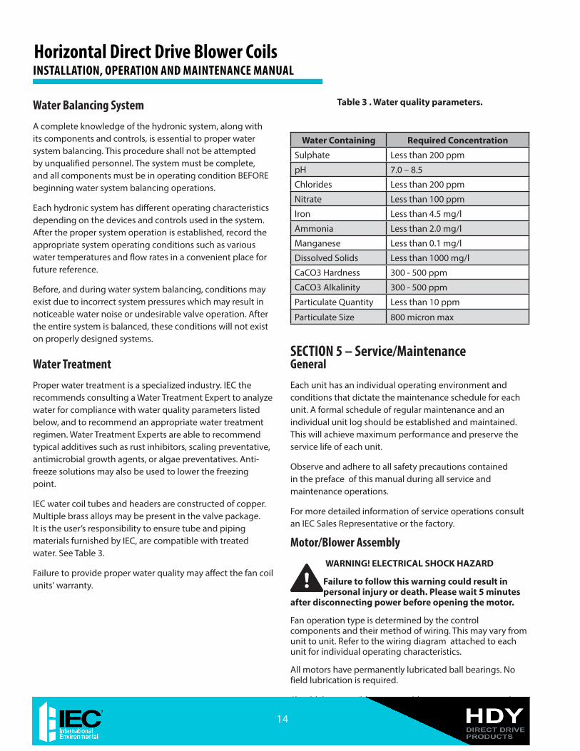
Water Containing Required Concentration
Sulphate Less than 200 ppm
pH 7.0 – 8.5
Chlorides Less than 200 ppm
Nitrate Less than 100 ppm
Iron Less than 4.5 mg/l
Ammonia Less than 2.0 mg/l
Manganese Less than 0.1 mg/l
Dissolved Solids Less than 1000 mg/l
CaCO3 Hardness 300 - 500 ppm
CaCO3 Alkalinity 300 - 500 ppm
Particulate Quantity Less than 10 ppm
Particulate Size 800 micron max
SECTION 5 – Service/Maintenance GeneralEach unit has an individual operating environment and conditions that dictate the main te nance schedule for each unit. A formal schedule of regular main tenance and an individual unit log should be established and maintained. This will achieve maximum performance and preserve the service life of each unit.
Observe and adhere to all safety precautions contained in the preface of this manual during all service and maintenance operations.
For more detailed information of service operations consult an IEC Sales Representative or the factory.
Failure to follow this warning could result in personal injury or death. Please wait 5 minutes
after disconnecting power before opening the motor.
Fan operation type is determined by the control components and their method of wiring. This may vary from unit to unit. Refer to the wiring diagram attached to each unit for individual operating characteristics.
All motors have permanently lubricated ball bearings. No field lubrication is required.
Should the motor/blower assembly require service, it may be
Table 3 . Water quality parameters.Water Balancing SystemA complete knowledge of the hydronic system, along with its components and controls, is essential to proper water system balancing. This procedure shall not be attempted by unqualified personnel. The system must be complete, and all components must be in operating condition BEFORE beginning water system balancing operations.
Each hydronic system has different operating characteristics depending on the devices and controls used in the system. After the proper system operation is established, record the appropriate system operating conditions such as various water temperatures and flow rates in a convenient place for future reference.
Before, and during water system balancing, conditions may exist due to incorrect system pressures which may result in noticeable water noise or undesirable valve operation. After the entire system is balanced, these conditions will not exist on properly designed systems.
Water TreatmentProper water treatment is a specialized industry. IEC the recommends consulting a Water Treatment Expert to analyze water for compliance with water quality parameters listed below, and to recommend an appropriate water treatment regimen. Water Treatment Experts are able to recommend typical additives such as rust inhibitors, scaling preventative, antimicrobial growth agents, or algae preventatives. Anti-freeze solutions may also be used to lower the freezing point.
IEC water coil tubes and headers are constructed of copper. Multiple brass alloys may be present in the valve package. It is the user’s responsibility to ensure tube and piping materials furnished by IEC, are compatible with treated water. See Table 3.
Failure to provide proper water quality may affect the fan coil units' warranty.
Horizontal Direct Drive Blower CoilsINSTALLATION, OPERATION AND MAINTENANCE MANUAL
14
removed from unit to facilitate operations such as motor or blower wheel/housing replacement, etc.
Dirt and dust must not be allowed to accumulate on blower wheel or housing. This can result in an unbalanced blower wheel condition which will damage a blower wheel or the motor. The wheel and housing must be cleaned periodically using a vacuum cleaner and a brush taking care not to dislodge factory balancing weights on the blower wheel blades.
CoilsCoils should be cleaned by brushing the entering air face between fins with a stiff brush. Brushing should be followed by cleaning with a vacuum cleaner. If a compressed air source is available, the coil may also be cleaned by blowing air through the coil fins from the leaving air face. This should again be followed by vacuuming. Units equipped with regularly replaced air filters will require less frequent coil cleaning.
Electric Resistance Heater AssemblyElectric resistance heaters typically require no scheduled maintenance when unit air filters are changed properly. The operation and service life may be affected by other conditions and equipment in the system. The two most important operating conditions for an electric heater are proper airflow and proper supply voltage. High supply voltage and/or poorly distributed or insufficient airflow over the element may result in the heater cycling on the high limit thermal cutout. Open-strip heaters have an automatic reset switch and high-limit thermal switch as a backup. Automatic limit switches reset after heater has cooled down.
Secondary high-limit thermal switches must be replaced once the circuit has been broken.
After proper airflow and supply power are assured, regular filter maintenance is important to provide clean air over the heater. Dirt allowed to deposit on the heating element will cause hot spots and eventual element burn through. These hot spots will normally not be enough to trip the high-limit thermal cut-out device and may not be evident until actual heater element failure.
Electrical Wiring and ControlsRefer to wiring diagram attached to unit for type and number of controls provided on each unit.
Verify integrity of incoming electrical connections at least twice during the first year of operation. Subsequently, all controls must be inspected periodically for proper operation. Wall thermostats may also become clogged with dust and lint, and must be periodically inspected and
cleaned to provide reliable operation.
CAUTION! When replacing any components such as fuses or relays, use only the exact type, size and voltage component as furnished from the
factory. Any deviation without factory authorization could result in personnel injury or damage to the unit. This will also void all factory warranties. Only factory supplied replacement parts ensure that the warranty and agency status remain in effect. All repair work shall be done in such a manner as to maintain the equipment in compliance with governing codes, ordinances and testing agency listings.
DrainInspect drain before initial startup, and prior to each cooling season to assure that drain trap and line are clear. When clogged, clear the debris so condensate easily flows.
Periodically inspect drain during cooling season to maintain a free-flowing condensate. Units are provided with a secondary or “tell-tale” drain connection that will indicate a clogged main-drain line by flow from “tell-tale” connection.
Should algae and/or bacteria growth become a concern, consult an air conditioning and refrigeration supply organization familiar with local conditions for chemicals, or other solutions available to control these agents.
15
Horizontal Direct Drive Blower Coils INSTALLATION, OPERATION AND MAINTENANCE MANUAL
Filters, Replacement,InstallationEach unit is equipped with return air filters. Filters must be periodically replaced.
HDY units' filters are 1", 2" or 4" thick. Filters can be easily accessed from the side or bottom of the filter rack . See Figure 17.
To remove filters from the side of the filter rack:
1. Remove the side access panel (A) of the filter rack by pulling tab at the bottom of the panel to free from magnets, and lower it out of the slot (B) in the top of the filter frame
2. Pull out dirty filters.
3. Replace with new appropriate size filters.
4. To re-install side access panel into filter rack :
a) Insert the tab of panel into the slot in filter frame's top (B).
b) Rotate panel toward the frame, ensure magnets are engaged.
To remove filters from the bottom of the filter rack:
1. Open hinged bottom access panel (C) - pull down to disengage magnets.
2. Pull out dirty filters.
3. Replace with new appropriate size filters.
4. Secure bottom access panels, make sure magnets are re-engaged.
HDY units are designed to accept various filter sizes depending on job requirements. Each filter frame is equipped with Filter Support Angle Brackets (D) and 1" or 2" filter slots on all four sides of filter frame. The Filter Support Angle Brackets (D) are designed to provide guidance and support to the new filter as it is being inserted.
In order to accommodate 1" and 2" filters, the bracket should be attached to corresponding holes on all (3) sides of the filter frame and secured with screws. When 4" filter is installed, the brackets should be stored for future use with different filter thickness, or discarded if 4" filter will always be used.
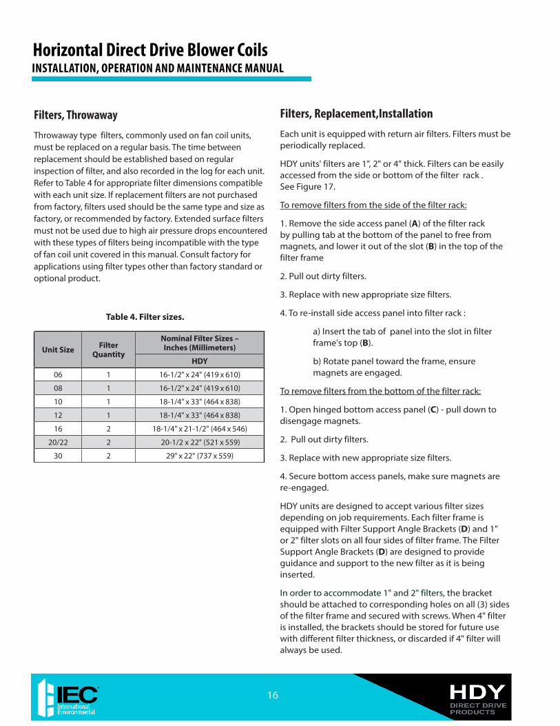
Filters, ThrowawayThrowaway type filters, commonly used on fan coil units, must be replaced on a regular basis. The time between replacement should be established based on regular inspection of filter, and also recorded in the log for each unit. Refer to Table 4 for appropriate filter dimensions compatible with each unit size. If replacement filters are not purchased from factory, filters used should be the same type and size as factory, or recommended by factory. Extended surface filters must not be used due to high air pressure drops encountered with these types of filters being incompatible with the type of fan coil unit covered in this manual. Consult factory for applications using filter types other than factory standard or optional product.
Table 4. Filter sizes.
Unit Size Filter Quantity
Nominal Filter Sizes – Inches (Millimeters)
HDY
06 1 16-1/2" x 24" (419 x 610)
08 1 16-1/2" x 24" (419 x 610)
10 1 18-1/4" x 33" (464 x 838)
12 1 18-1/4" x 33" (464 x 838)
16 2 18-1/4" x 21-1/2" (464 x 546)
20/22 2 20-1/2 x 22" (521 x 559)
30 2 29" x 22" (737 x 559)
Horizontal Direct Drive Blower CoilsINSTALLATION, OPERATION AND MAINTENANCE MANUAL
16
Figure 17. Filter rack
4” FILTER
2” FILTER
1” FILTER
MAGNETS
DETAIL X
SEE DETAIL X
SEE DETAIL Y DETAIL Y
1” FILTER MOUNTING HOLES
2” FILTER MOUNTING HOLES
D - FILTER SUPPORT ANGLE BRACKET
A
17
Horizontal Direct Drive Blower Coils INSTALLATION, OPERATION AND MAINTENANCE MANUAL
Figure 18. Hydronic coil piping connection diagram.Piping Connection Location (Centerline to Centerline) – Hydronic Cooling and Heating Coils
NOTES: 1. RH shown, LH opposite. 2. All dimensions are +/- 1/4" (6 mm). 3. Product specifications are subject to changes without notice. 4. Dimensions in parenthesis are shown in millimeters. 5. Allow adequate spacing or maneuverability around unit to allow service through recommended access area. 6. “C” dimension is measured from coil side of unit. 7. Mixing Box option will vary return duct dimensions, refer to mixing box submittal. 8. Auxiliary control box required with 3-speed EC motors and/or cabinet lighting option, not required with low voltage (0-10V) controls.
Horizontal Direct Drive Blower CoilsINSTALLATION, OPERATION AND MAINTENANCE MANUAL
20
Figure 21. HDY unit with Mixing Box submittal drawing.Drawing is not to scale and is provided for reference only.
Dimensions may vary with options ordered. Consult IEC website for up-to-date drawings.
NOTES:1. RH shown, LH opposite. 2. All dimensions are +/- 1/4” (6 mm). 3. Product specifications are subject to changes without notice. 4. Dimensions in parenthesis are shown in (millimeters). 5. Allow adequate spacing or maneuverability around unit to allow service through recommended access area. 6. “C” dimension is measured from coil side of unit. 7. Mixing Box option will vary return duct dimensions, refer to mixing box submittal. 8. Mixing Box options include: a) Knockdown base rails for field assembly; b) Pre-assembled Mixing Box. 9. Linkage kit supplied with Mixing Box is provided for field installation of actuator. 10. Add 2”(51) if using a Prefilter, or 4”(102) filter. 11. Auxiliary control box required with 3-speed EC motors and/or cabinet lighting option, not required with low voltage (0-10V) controls.
21
Horizontal Direct Drive Blower Coils INSTALLATION, OPERATION AND MAINTENANCE MANUAL
1.5 4.2 3.6 1.8 X − X − X − X − − − − − − − − − − −
2.0 5.6 4.8 2.4 X − X − X − X − − − − − − − − − − −
2.5 6.9 6.0 3.0 X − X − X − X − − X − − − − − − − −
3.0 8.3 7.2 3.6 X _ X _ X _ X _ − X _ − − − − − − −
3.5 9.7 8.4 4.2 X _ X _ X _ X _ − X _ − X _ − − − −
4.0 11.1 9.6 4.8 X X X X X X X X − X X − X X − − − −
4.5 12.5 10.8 5.4 X X X X X X X X − X X − X X − − − −
5.0 13.9 12.0 6.0 X X X X X X X X − X X − X X − − − −
6.0 16.7 14.4 7.2 X X X X X X X X − X X − X X − X X −
7.0 19.4 16.8 8.4 − − X X X X X X − X X − X X − X X −
8.0 22.2 19.2 9.6 − − X X X X X X − X X − X X − X X −
9.9 27.5 23.8 11.9 − − − − X X X X − X X − X X − X X −
12.0 33.3 28.9 14.4 − − − − − − X X X X X X X X X X X X
14.0 38.9 33.7 16.8 − − − − − − − − − X X X X X X X X X
15.0 41.6 36.1 18.0 − − − − − − − − − X X X X X X X X X
16.0 − 38.5 19.2 − − − − − − − − − X X X X X X X X X
18.0 − − 21.7 − − − − − − − − − − − − X X X X X X
19.9 − − 23.9 − − − − − − − − − − − − X X X X X X
25.0 − − 30.1 − − − − − − − − − − − − − − − X X X
30.0 − − 36.1 − − − − − − − − − − − − − − − X X X
X Available option− Not available optionNOTES:1. Electric Heating Capacities BTUh)=Heater kW x 34132. Electric Heater Amp. for 3-phase Power = (Heater kW x 1000)/(Applied Voltage x 1.73).
Table 8. Three Phase Electric Heater Availability
23
Horizontal Direct Drive Blower Coils INSTALLATION, OPERATION AND MAINTENANCE MANUAL
MOTOR TYPE VOLTAGE
UNIT SIZE
06, 10 08, 12, 16, 20 22 30
MOTOR HORSEPOWER AND FLA
1/2 HP 1 HP 1-1/2 HP 3 HP
1-PHASE SINGLE SPEED
STANDARD EFFICIENCY
115V/1 PHASE/50-60 HZ 6.4 10.7 N/A N/A
208V/1 PHASE/50-60 HZ 3.8 6.3 N/A N/A
230V/1 PHASE/50-60 HZ 3.6 5.8 N/A N/A
277V/1 PHASE/50-60 HZ 3.2 5.1 N/A N/A
3-PHASE SINGLE SPEED
STANDARD EFFICIENCY
208V/3 PHASE/50-60 HZ 2.0 3.7 4.4 8.9
230V/3 PHASE/50-60 HZ 1.85 3.3 4.4 8.9
460V/3 PHASE/50-60 HZ 1.0 1.75 2.2 4.4
Table 9. Motor Performance Data (Full Load AMPS)
NOTES:
1. Motor Full Load amps refer to National Electric Code (NEC) amps; actual motor nameplate amps may vary. 2. Motors are UL recognized, constant speed brushless DC type, open drip proof, ball bearing, multi-voltage options, 0-10 V control.
Horizontal Direct Drive Blower CoilsINSTALLATION, OPERATION AND MAINTENANCE MANUAL
24
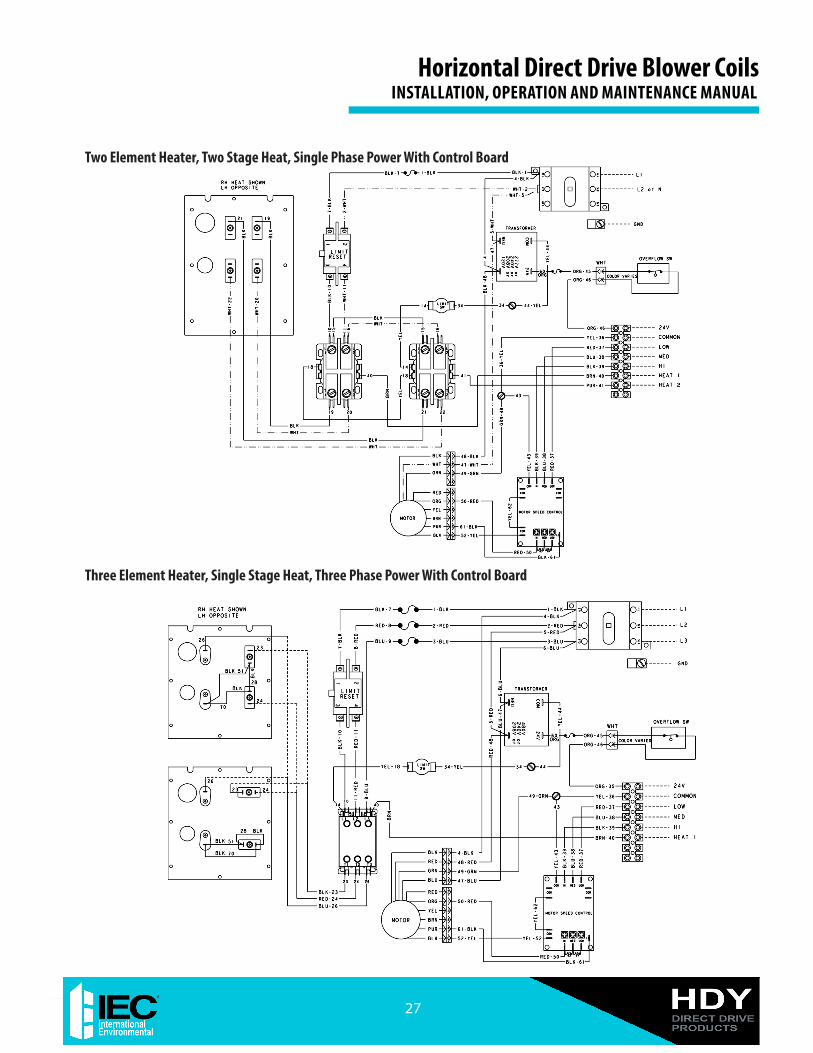
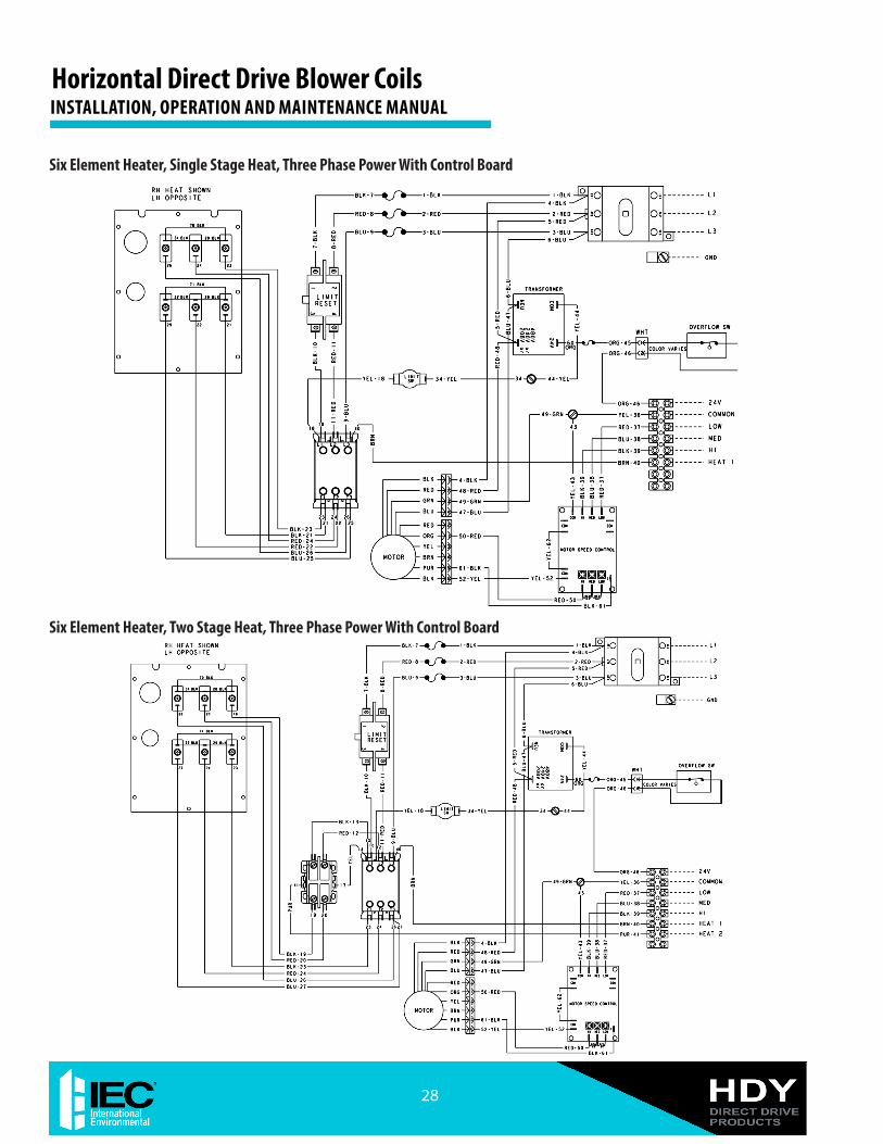
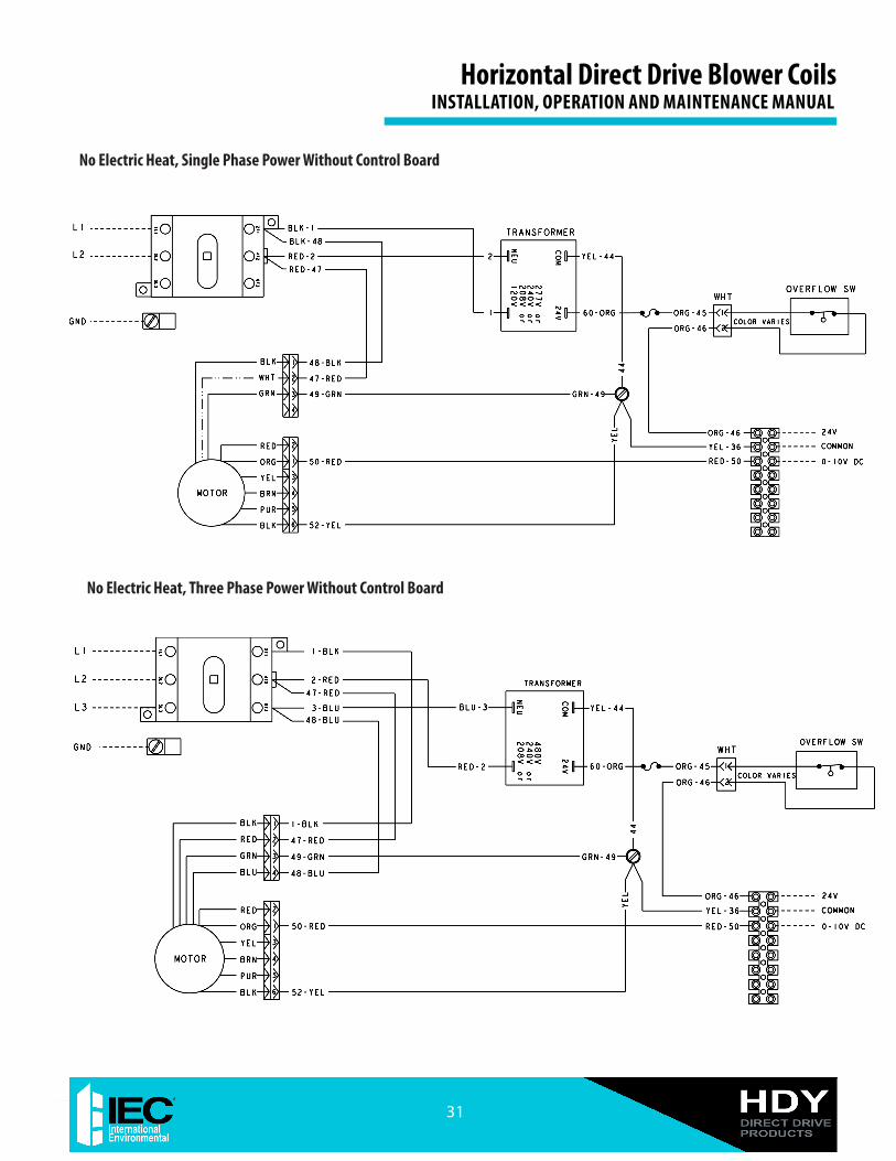
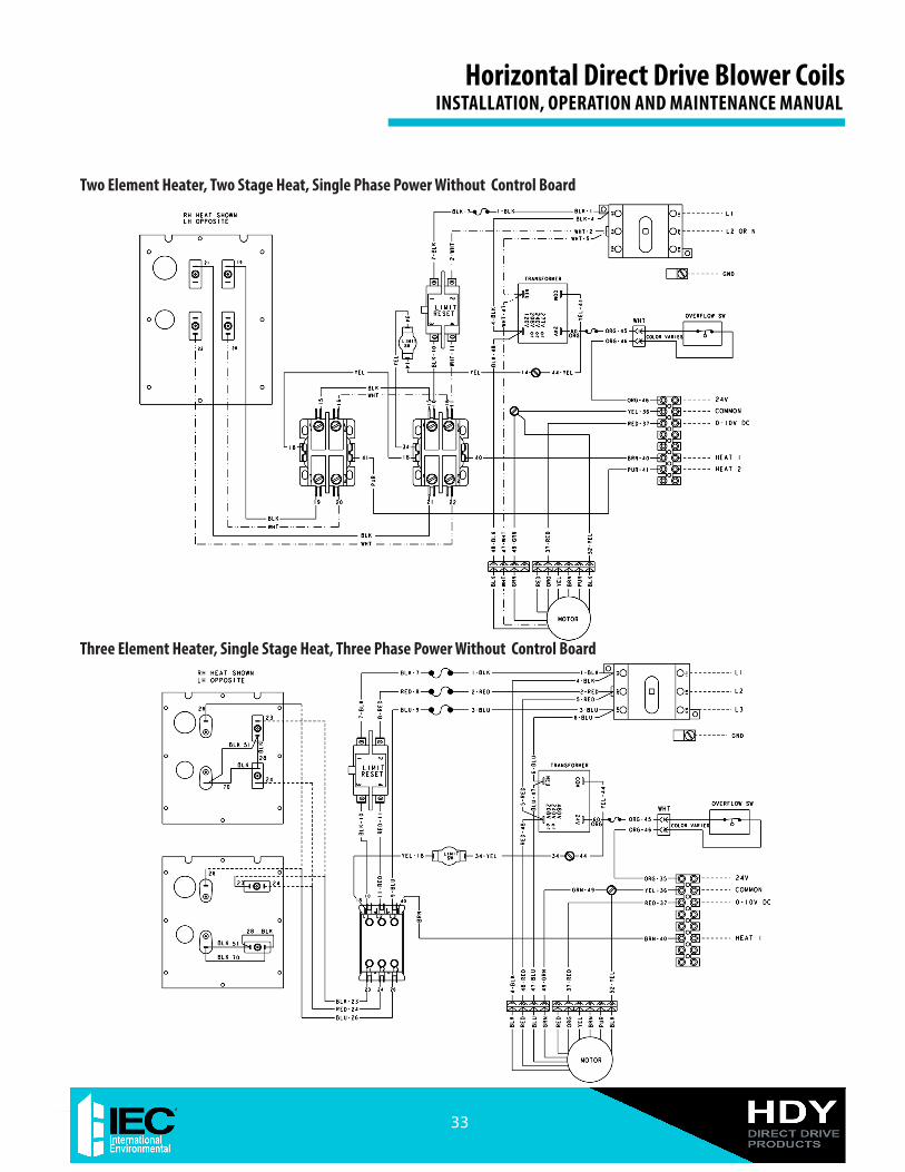
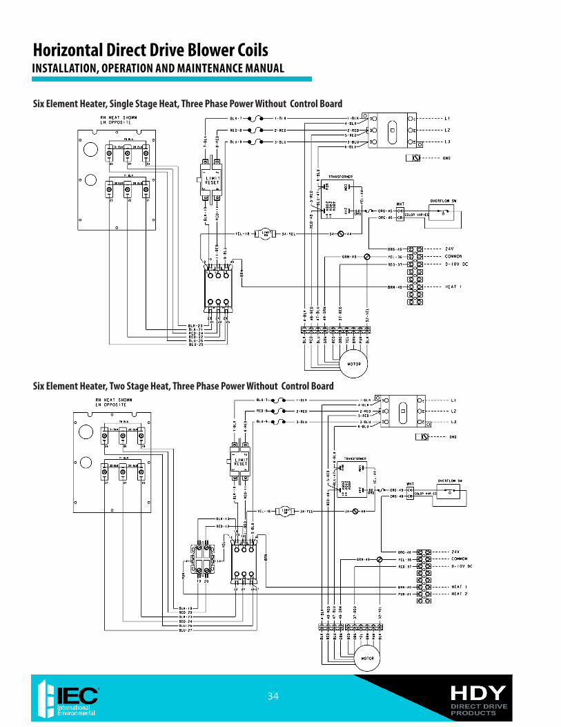
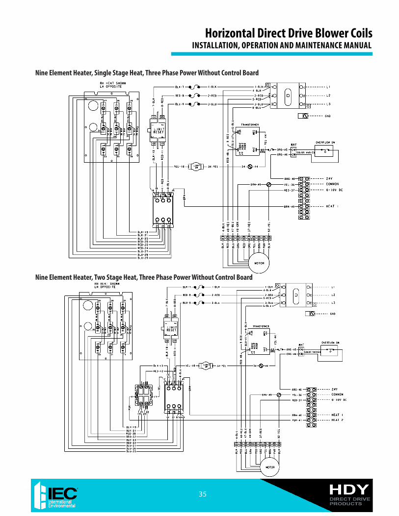
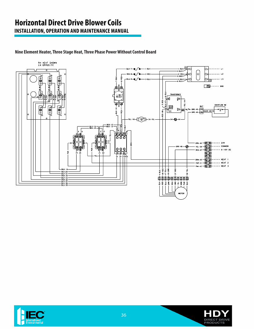
WARNING: Wiring diagrams are provided as an example only, ALWAYS refer to WIRING DIAGRAM attached to the unit!
25
Horizontal Direct Drive Blower Coils INSTALLATION, OPERATION AND MAINTENANCE MANUAL
Appendix I - Typical Wiring Diagram Examples
No Electric Heat, Three Phase Power With Control Board
No Electric Heat, Single Phase Power With Control Board
Horizontal Direct Drive Blower CoilsINSTALLATION, OPERATION AND MAINTENANCE MANUAL
26
Single Element Heater, Single Stage Heat, Single Phase Power With Control Board
Two Element Heater, Single Stage Heat, Single Phase Power With Control Board
27
Horizontal Direct Drive Blower Coils INSTALLATION, OPERATION AND MAINTENANCE MANUAL
Two Element Heater, Two Stage Heat, Single Phase Power With Control Board
Three Element Heater, Single Stage Heat, Three Phase Power With Control Board
Horizontal Direct Drive Blower CoilsINSTALLATION, OPERATION AND MAINTENANCE MANUAL
28
Six Element Heater, Single Stage Heat, Three Phase Power With Control Board
Six Element Heater, Two Stage Heat, Three Phase Power With Control Board
29
Horizontal Direct Drive Blower Coils INSTALLATION, OPERATION AND MAINTENANCE MANUAL
Nine Element Heater, Single Stage Heat, Three Phase Power With Control Board
Nine Element Heater, Two Stage Heat, Three Phase Power With Control Board
Horizontal Direct Drive Blower CoilsINSTALLATION, OPERATION AND MAINTENANCE MANUAL
30
Nine Element Heater, Three Stage Heat, Three Phase Power With Control Board
31
Horizontal Direct Drive Blower Coils INSTALLATION, OPERATION AND MAINTENANCE MANUAL
No Electric Heat, Single Phase Power Without Control Board
No Electric Heat, Three Phase Power Without Control Board
Horizontal Direct Drive Blower CoilsINSTALLATION, OPERATION AND MAINTENANCE MANUAL
32
Single Element Heater, Single Stage Heat, Single Phase Power Without Control Board
33
Horizontal Direct Drive Blower Coils INSTALLATION, OPERATION AND MAINTENANCE MANUAL
Two Element Heater, Two Stage Heat, Single Phase Power Without Control Board
Three Element Heater, Single Stage Heat, Three Phase Power Without Control Board
Horizontal Direct Drive Blower CoilsINSTALLATION, OPERATION AND MAINTENANCE MANUAL
34
Six Element Heater, Single Stage Heat, Three Phase Power Without Control Board
Six Element Heater, Two Stage Heat, Three Phase Power Without Control Board
35
Horizontal Direct Drive Blower Coils INSTALLATION, OPERATION AND MAINTENANCE MANUAL
Nine Element Heater, Single Stage Heat, Three Phase Power Without Control Board
Nine Element Heater, Two Stage Heat, Three Phase Power Without Control Board
Horizontal Direct Drive Blower CoilsINSTALLATION, OPERATION AND MAINTENANCE MANUAL
36
Nine Element Heater, Three Stage Heat, Three Phase Power Without Control Board
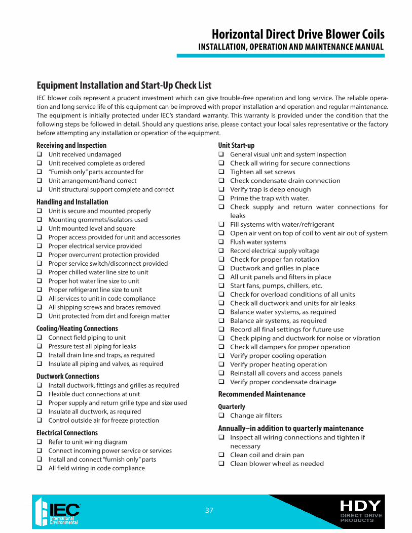
Equipment Installation and Start-Up Check ListIEC blower coils represent a prudent investment which can give trouble-free operation and long service. The reliable opera-tion and long service life of this equipment can be improved with proper installation and operation and regular maintenance. The equipment is initially protected under IEC’s standard warranty. This warranty is provided under the condition that the following steps be followed in detail. Should any questions arise, please contact your local sales representative or the factory before attempting any installation or operation of the equipment.
Receiving and Inspection Unit received undamaged Unit received complete as ordered “Furnish only” parts accounted for Unit arrangement/hand correct Unit structural support complete and correct
Handling and Installation Unit is secure and mounted properly Mounting grommets/isolators used Unit mounted level and square Proper access provided for unit and accessories Proper electrical service provided Proper overcurrent protection provided Proper service switch/disconnect provided Proper chilled water line size to unit Proper hot water line size to unit Proper refrigerant line size to unit All services to unit in code compliance All shipping screws and braces removed Unit protected from dirt and foreign matter
Cooling/Heating Connections Connect field piping to unit Pressure test all piping for leaks Install drain line and traps, as required Insulate all piping and valves, as required
Ductwork Connections Install ductwork, fittings and grilles as required Flexible duct connections at unit Proper supply and return grille type and size used Insulate all ductwork, as required Control outside air for freeze protection
Electrical Connections Refer to unit wiring diagram Connect incoming power service or services Install and connect “furnish only” parts All field wiring in code compliance
Unit Start-up General visual unit and system inspection Check all wiring for secure connections Tighten all set screws Check condensate drain connection Verify trap is deep enough Prime the trap with water. Check supply and return water connections for
leaks Fill systems with water/refrigerant Open air vent on top of coil to vent air out of system Flush water systems Record electrical supply voltage Check for proper fan rotation Ductwork and grilles in place All unit panels and filters in place Start fans, pumps, chillers, etc. Check for overload conditions of all units Check all ductwork and units for air leaks Balance water systems, as required Balance air systems, as required Record all final settings for future use Check piping and ductwork for noise or vibration Check all dampers for proper operation Verify proper cooling operation Verify proper heating operation Reinstall all covers and access panels Verify proper condensate drainage
Recommended Maintenance
Quarterly Change air filters
Annually–in addition to quarterly maintenance Inspect all wiring connections and tighten if
necessary Clean coil and drain pan Clean blower wheel as needed
37
Horizontal Direct Drive Blower Coils INSTALLATION, OPERATION AND MAINTENANCE MANUAL
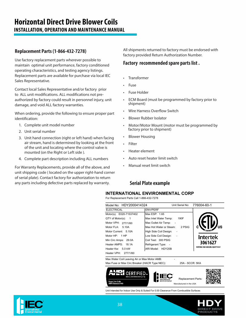
Replacement Parts (1-866-432-7278)
Use factory replacement parts wherever possible to maintain optimal unit performance, factory conditioned operating characteristics, and testing agency listings. Replacement parts are available for purchase via local IEC Sales Representative.
Contact local Sales Representative and/or factory prior to ALL unit modifications. ALL modifications not pre-authorized by factory could result in personnel injury, unit damage, and void ALL factory warranties.
When ordering, provide the following to ensure proper part identification:
1. Complete unit model number
2. Unit serial number
3. Unit hand connection (right or left hand) when facing air stream, hand is determined by looking at the front of the unit and locating where the control valve is mounted (on the Right or Left side ).
4. Complete part description including ALL numbers
For Warranty Replacements, provide all of the above, and unit shipping code ( located on the upper right-hand corner of serial plate). Contact factory for authorization to return any parts including defective parts replaced by warranty.
All shipments returned to factory must be endorsed with factory provided Return Authorization Number.
Factory recommended spare parts list .
• Transformer
• Fuse
• Fuse Holder
• ECM Board (must be programmed by factory prior to shipment)
• Wire Harness Overflow Switch
• Blower Rubber Isolator
• Motor/Motor Mount (motor must be programmed by factory prior to shipment)
• Blower Housing
• Filter
• Heater element
• Auto reset heater limit switch
• Manual reset limit switch
Serial Plate example
INTERNATIONAL ENVIRONMENTAL CORP
Max Water Coil Leaving Air or Max Motor AMB:Max Fuse or Max Circ Breaker (HACR Type NEC):
Unit Intended for Indoor Use Only & Suited For 0.00 Clearance From Combustible Surfaces
-25A - SCCR: 5KA
Unit Serial No:Model No: HDY2000414324 776004-60-1
For Replacement Parts Call 1-866-432-7278
ELECTRICAL ENV/PERFMotor(s):
Motor VPH:Motor FLA:
Heater AMPS:
QTY of Motor(s):
Motor HP:Min Circ Amps:
Heater VPH:
E020-71537402
277/1/605.10A
18.1A5.0 kW
1
1 HP29.0A
277/1/60
Max ESP:Max Inlet Water Temp:
Coil Test:
High Side Coil Design:
Refrigerant Type:
1.65
300 PSIG
-
-
Max Outlet Air Temp:Max Hot Water or Steam:
ARI Model:
Low Side Coil Design:
-
HDY20B
-
190F
2 PSIG
Heater Kw:
Motor Current: 5.10A
Replacement Parts:
Manufactured in the USA
Horizontal Direct Drive Blower CoilsINSTALLATION, OPERATION AND MAINTENANCE MANUAL
38
Forms\IEC\Standard Forms\Word Files\IEC Terms and Conditions 1-Page 09-10.doc
TERMS AND CONDITIONS 1. Orders shall not be binding upon International Environmental Corporation, an Oklahoma
corporation (hereinafter referred to as “IEC”) unless accepted by an authorized representative of IEC at its office in Oklahoma City, Oklahoma. No distributor, sales representative or any other person or entity (except authorized employees of IEC at its office in Oklahoma City, Oklahoma) has any authority whatsoever to bind IEC to any representation or agreement of any kind.
2. IEC does not build items to plans and specifications. IEC agrees to furnish only the items as
described in IEC’s acknowledgment unless IEC’s office in Oklahoma City, Oklahoma has previously received and accepted, in writing, approved submittals from Purchaser.
3. Prices acknowledged are firm only if Purchaser releases the goods covered by this order for
immediate production by IEC within sixty (60) days from the date of Purchaser’s initial offer to purchase and for shipment by IEC within IEC’s estimated shipping date, unless otherwise agreed to in writing by IEC at its office in Oklahoma City, Oklahoma. If Purchaser does not meet the terms and conditions of this paragraph, the prices are subject to escalation to those prices in effect at time of shipment without notice to Purchaser.
4. All prices are F.O.B. IEC’s factory, unless otherwise agreed by IEC in writing; and, all payments
and prices shall be in U.S.A. dollars. 5. If goods are released for production but IEC is prevented by the Purchaser from shipping upon
completion or by IEC’s estimated shipping date, whichever is later, IEC may at its option, in addition to all other remedies, invoice Purchaser to be payable within thirty (30) days and store the goods at Purchaser’s sole expense.
6. Title to and risk of loss to the goods passes to the Purchaser F.O.B. IEC’s factory. 7. Disclaimer It is expressly understood that unless a statement is specifically identified as a warranty,
statements made by IEC or its representatives relating to IEC’s products, whether oral, written or contained in any sales literature, catalog or any other agreement, are not express warranties and do not form a part of the basis of the bargain, but are merely IEC’s opinion or commendation of IEC’s products. EXCEPT AS SPECIFICALLY SET FORTH HEREIN, THERE IS NO EXPRESS WARRANTY AS TO ANY OF IEC’S PRODUCTS. IEC MAKES NO WARRANTY AGAINST LATENT DEFECTS. IEC MAKES NO WARRANTY OF MERCHANTABILITY OF THE GOODS OR OF THE FITNESS OF THE GOODS FOR ANY PARTICULAR PURPOSE.
8. Grant of Limited Express Warranty IEC warrants IEC products purchased and retained in the United States of America and Canada to
be free from defects in material and workmanship under normal use and maintenance as follows: (1) All complete fan coil units built or sold by IEC for twelve (12) months from date of unit start up or eighteen (18) months from date of shipment (from factory), whichever comes first.
All parts must be returned to IEC’s factory in Oklahoma City, Oklahoma, freight prepaid, no later
than sixty (60) days after the date of the failure of the part; if IEC determines the part to be defective and within IEC’s Limited Express Warranty, IEC shall, when such part has been either replaced or repaired, return such to a factory recognized contractor or service organization, F.O.B. IEC’s factory, Oklahoma City, Oklahoma, freight prepaid. The warranty on any parts repaired or replaced under warranty expires at the end of the original warranty period. For information and warranty service contact:
International Environmental Corporation Customer Service 5000 West I-40 Oklahoma City, OK 73128 (405) 605-5000
This warranty does not cover and does not apply to: (1) Air filters, fuses, fluids; (2) Products
relocated after initial installation; (3) Any portion or component of any system that is not supplied by IEC, regardless of the cause of the failure of such portion or component; (4) Products on which the unit identification tags or labels have been removed or defaced; (5) Products on which payment to IEC is or has been in default; (6) Products which have defects or damage which result from improper installation, wiring, electrical imbalance characteristics or maintenance; or are caused by accident, misuse or abuse, fire, flood, alteration or misapplication of the product; (7) Products which have defects or damage which result from a contaminated or corrosive air or liquid supply or operation at abnormal temperatures; (8) Mold, fungus or bacteria damages; (9) Products subjected to corrosion or abrasion; (10) Products manufactured or supplied by others; (11) Products which have been subjected to misuse, negligence or accidents; (12) Products which have been operated in a manner contrary to IEC’s printed instructions; or (13) Products which have defects, damage or insufficient performance as a result of insufficient or incorrect system design or the improper application of IEC’s products.
IEC is not responsible for: (1) The cost of any fluids or other system components, or associated
labor to repair or replace the same, which is incurred as a result of a defective part covered by IEC’s Limited Express Warranty; (2) The costs of labor, materials or service incurred in removal of the defective part, or in obtaining and replacing the new or repaired part; or, (3) Transportation costs of the defective part from the installation site to IEC or of the return of any part not covered by IEC’s Limited Express Warranty.
Limitation: This Limited Express Warranty is given in lieu of all other warranties. If, notwithstanding the disclaimers contained herein, it is determined that other warranties exist, any such warranties, including without limitation any express warranties or any implied warranties of fitness for particular purpose and merchantability, shall be limited to the duration of the Limited Express Warranty.
9. Limitation of Remedies In the event of a breach of the Limited Express Warranty, IEC will only be obligated at IEC’s
option to repair the failed part or unit or to furnish a new or rebuilt part or unit in exchange for the part or unit which has failed. If after written notice to IEC’s factory in Oklahoma City, Oklahoma of each defect, malfunction or other failure and a reasonable number of attempts by IEC to correct the defect, malfunction or other failure and the remedy fails of its essential purpose, IEC shall refund the purchase price paid to IEC in exchange for the return of the sold good(s). Said refund shall be the maximum liability of IEC. THIS REMEDY IS THE SOLE AND EXCLUSIVE REMEDY OF THE BUYER OR THEIR PURCHASER AGAINST IEC FOR BREACH OF CONTRACT, FOR BREACH OF ANY WARRANTY OR FOR IEC’S NEGLIGENCE OR IN STRICT LIABILITY.
10. Limitation of Liability IEC shall have no liability for any damages if IEC’s performance is delayed for any reason or is
prevented to any extent by any event such as, but not limited to: any war, civil unrest, government restrictions or restraints, strikes, or work stoppages, fire, flood, accident, shortages of transportation, fuel, material or labor, acts of God or any other reason beyond the sole control of IEC. IEC EXPRESSLY DISCLAIMS AND EXCLUDES ANY LIABILITY FOR CONSEQUENTIAL OR INCIDENTAL DAMAGE IN CONTRACT, FOR BREACH OF ANY EXPRESS OR IMPLIED WARRANTY, OR IN TORT, WHETHER FOR IEC’s NEGLIGENCE OR AS STRICT LIABILITY.
11. IEC shall have no system design, application or maintenance responsibility or responsibility for
mold, fungus or bacteria to Purchaser or any other third party. 12. All sales, goods and services, use, excise, value added, transportation, privilege, occupational
consumption, storage, document, transaction or other taxes which may be levied by any taxing authority as a result of this transaction shall be paid by the Purchaser.
13. Unless otherwise agreed to in writing by IEC any technical data furnished in conjunction with this
order and not obtainable from another source shall not be duplicated, used, or disclosed in whole or in part for any purpose other than to evaluate this order.
14. IEC shall have no liability or other obligation hereunder, if IEC’s performance is delayed for any
reason or is prevented to any extent by any event such as, but not limited to: any act of God, strike or work stoppage, fire, flood, accident, allocation, or other controls of Government authorities, shortages of transportation, fuel, material or labor, or any other cause beyond IEC’s sole control. Any shipping date stated by IEC is IEC’s best estimate but IEC makes no guarantee of shipment by any such date and shall have no liability or other obligation for failure to ship on such date, regardless of cause.
15. Payment terms are net thirty (30) days from date of shipment on approved credit. One and one
half percent (1 1/2%) per month (18% annual rate) may be charged on past due accounts or the highest rate permitted by applicable law, whichever is lesser. In the event the account is placed for collection, Purchaser shall be responsible for all reasonable attorneys fees or costs on a solicitor and client basis, plus all other costs and expenses incurred by IEC in securing payment.
16. Purchaser shall not cancel the contract without prior written consent of an authorized
representative of IEC at its offices in Oklahoma City, Oklahoma. In the event Purchaser cancels the contract with the prior written consent of IEC after the Purchaser’s offer to purchase is received and acknowledged in writing, IEC shall be entitled to receive from Purchaser IEC’s cost incurred to time of cancellation plus a reasonable allowance for overhead and profit.
17. Purchaser shall not assign any of its interest or rights under this agreement without written consent
of IEC. 18. IEC will protect all its lien rights. IEC will not furnish lien waivers or releases until IEC receives
payment, in full, at its office in Oklahoma City, Oklahoma from Purchaser for the goods covered by this order. There is no authorized retainage for any reason.
19. This Agreement shall be construed, and the rights and liabilities of the parties hereunder shall be
determined in accordance with the laws of the State of Oklahoma. If it shall be found that any portion of this agreement violates any particular law of the United States or any state in the United States having jurisdiction or, if applicable, any law of Canada or any province or territory in Canada having jurisdiction, such portion of the agreement shall be of no force and effect in that political unit, division or sub-division in which they are illegal or unenforceable and the agreement shall be treated as if such portion or portions had not been inserted. In the event that any dispute or disagreement in connection with any order should arise or exist between Purchaser and IEC, jurisdiction and venue for any legal action shall be, if IEC so elects, exclusively in the state or federal courts in Oklahoma County, Oklahoma. The statute of limitations on any claim of the Purchaser against the IEC shall be one (1) year from the date the cause of action accrues.
20. Without regard to any other agreement, all obligations of Purchaser to IEC shall become
immediately due and payable if Purchaser becomes insolvent or if Purchaser does not make payments when due or breaches any other agreement or fails to perform any obligation.
21. All orders are expressly limited and made conditional upon acceptance by Purchaser of the terms
and conditions set forth above without change. There shall be no understandings, agreements, or obligations (outside these terms and conditions) unless specifically set forth in writing and accepted by signature of an authorized representative of IEC in Oklahoma City, Oklahoma.
22. The parties hereto have requested that these presents and all judicial proceedings relating thereto
be drafted in English. Les parties aux présentes ont demandé à ce que les présentes et toutes procedures judiciaires y afférentes soient rédigées en anglais
39
Horizontal Direct Drive Blower Coils INSTALLATION, OPERATION AND MAINTENANCE MANUAL
Contact your local IEC Sales Representative for further details and pricing applicable to this product. Visit our website (iec-okc.com) to find your local IEC Sales Rep.