25
INSTALLATION REQUIREMENTS 2015 NBIC PART,1 Joel T. Amato Chief Boiler Inspector
INSTALLATION REQUIREMENTS 2015 NBIC PART,1
Joel T. Amato Chief Boiler Inspector
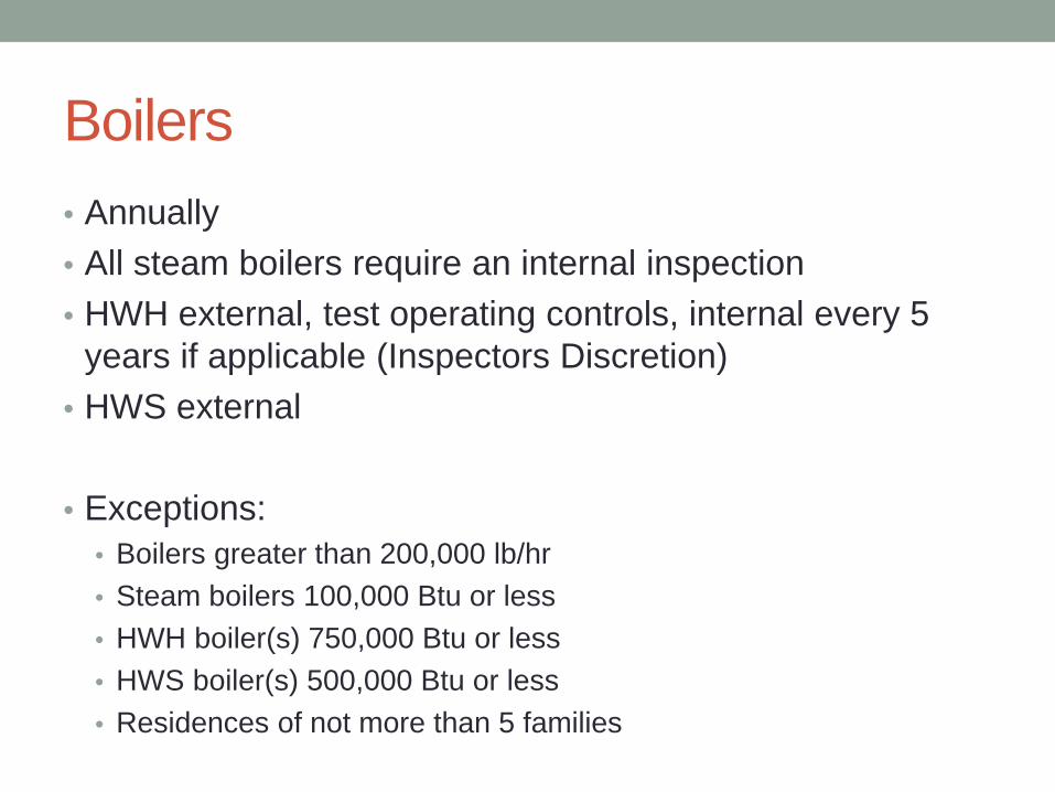
Boilers • Annually • All steam boilers require an internal inspection • HWH external, test operating controls, internal every 5
years if applicable (Inspectors Discretion) • HWS external
• Exceptions:
• Boilers greater than 200,000 lb/hr • Steam boilers 100,000 Btu or less • HWH boiler(s) 750,000 Btu or less • HWS boiler(s) 500,000 Btu or less • Residences of not more than 5 families
Pressure Vessels
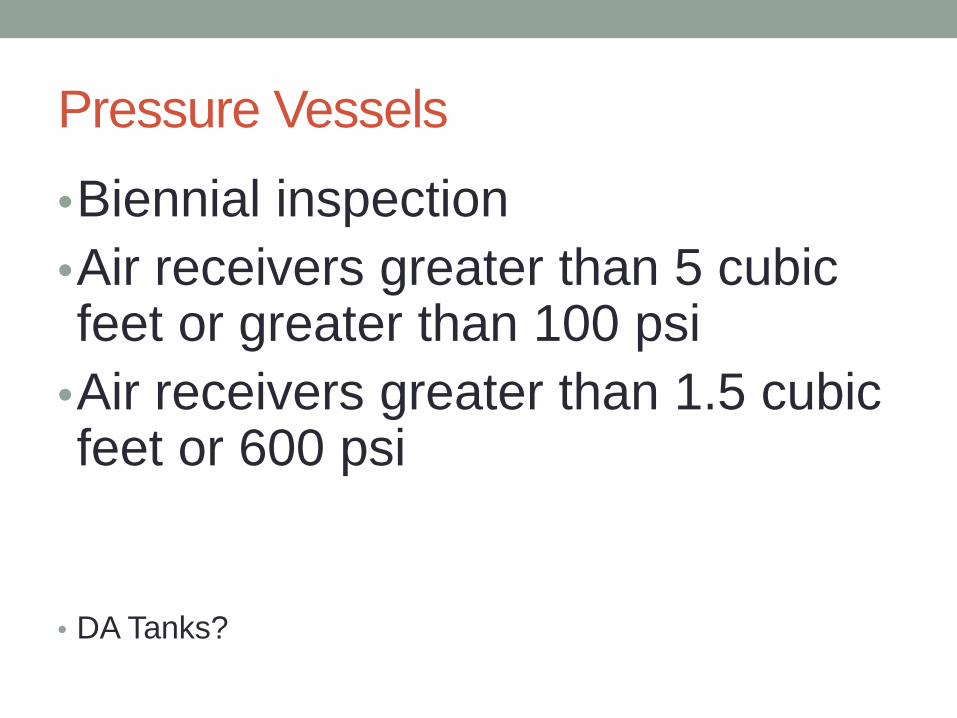
•Biennial inspection •Air receivers greater than 5 cubic feet or greater than 100 psi
•Air receivers greater than 1.5 cubic feet or 600 psi
• DA Tanks?
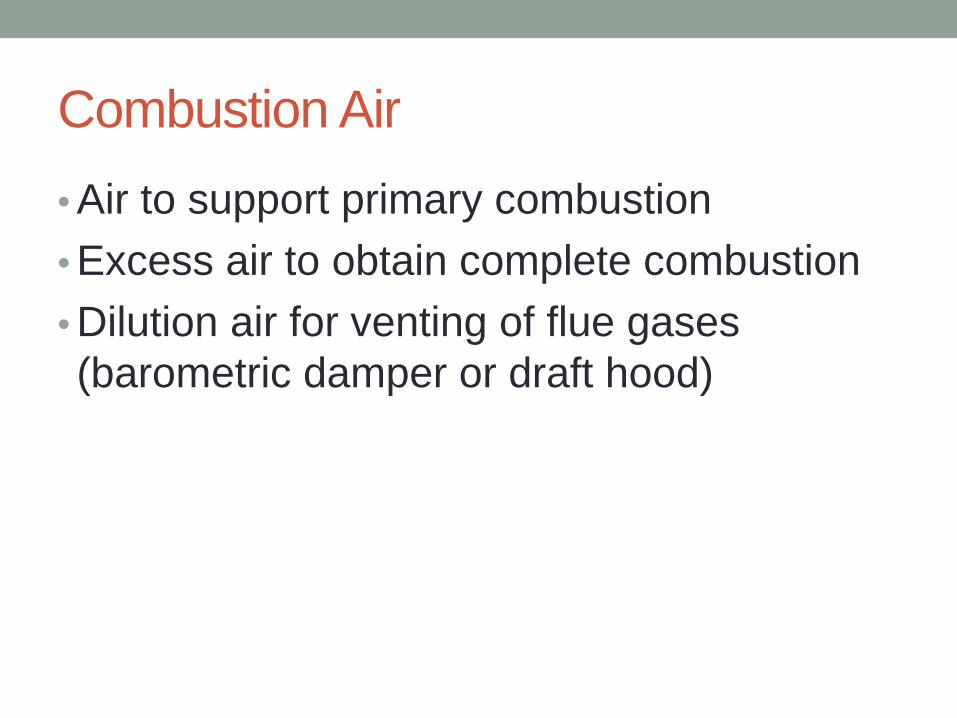
Combustion Air • Air to support primary combustion • Excess air to obtain complete combustion • Dilution air for venting of flue gases (barometric damper or draft hood)
Current, NBIC Part 1, 2.5.4 and 3.5.4 a) Minimum of 19.5 % oxygen b) Unobstructed openings 1 square inch per 2,000 btu’s c) Power Ventilators .2cfm per 1,000 btu’s d) Power ventilators or fans must be interlocked with burners e) Independent duct must be installed per boiler manufacturer
(sealed combustion) f) Size of openings in (b) may be reduced if approved by
jurisdiction g) Steam and water lines should not be routed across
combustion air openings • Same requirement for Power Boilers and Heating boilers with
the exception of 3.5.4 (e) combustion air supplied by an independent duct to a Heating boiler.

NBIC Part 1, • Combustion Air • Currently no justification for combustion air openings for large industrial boilers with power burners. As a result the openings can be excessively sized.
• NBIC Example: 10,000,000 btu input power boiler must have a free air opening of 5,000 square inches to the outside. (300 horsepower, 150 for licensing purposes) • 34.7 square feet • 5.8 feet by 5.8 feet square

Power Boiler VS Heating Boiler • Power Burner
• Uses a fan to force air into the boiler for combustion • Requires smaller openings for combustion air
• Power Burner with draft control device
• Uses a fan to force air into the boiler for combustion • Barometric damper for dilution air
• Atmospheric Burner
• Utilizes natural draft to provide air for combustion • Requires larger openings for combustion air
• Why does NBIC separate them as Power Boiler and Heating
Boiler and not as Power Burner and Atmospheric Burner?

Minnesota Building Code • Power Burner
• .2 square inches per 1,000 Btu, for appliances equipped with draft control device
• .1 square inches per 1,000 Btu, for appliances without draft control device • Example: 10,000,000 with draft control = 3.7 foot by 3.7 foot opening • Example: 10,000,000 without draft control = 2.6 foot by 2.6 foot opening
• Atmospheric Burner • 1 square inch per 3,000 Btu’s
• Example: 10,000,000 = 4.8 X 4.8 free opening

Heating Boiler Clearances • Top- 36 inches • With Manway- 84 inches • Alternative clearances in accordance with the
manufacturer's recommendations are subject to acceptance by the jurisdiction
• Modular boilers in accordance with Manufacturers recommendations, subject to acceptance by the jurisdiction.
• Heating boilers shall be location so that adequate space is provided for proper operation, maintenance, and inspection.
Heating Boilers, Water Supply • A connection to add water or fill the boiler shall be
provided • A valve or threaded plug may be used to shut off the fill
connection when the boiler is in service. • A means shall be provided at or near the boiler to prevent
back-feeding. The device must be rated for the boiler pressure and temperature.

Steam Heat, HWH, HWS, and Potable Water heaters. • 3.5.3.1 and 3.5.3.2 • Shutdown switch shall be located outside the equipment room door and marked for easy identification.
• Boiler disconnect switch capable of being locked in the open position shall be installed.

Steam Heating Boilers, 3.8.1 • Pressure Gage
• 30 to 60 psi, travel of pointer at least 3 inches • Water gage glass
• Lowest visible part of gage glass shall be at least 1 inch above the lowest permissible water level established by the manufacturer. Shall be indicated on boiler exterior.
• Both low water cut offs must shut off the boiler at or before the lowest visible part the sight glass.
• Pressure Control • Shall have two pressure operated controls
• Operating control • High pressure limit • Shut off valves of any type shall not be placed between the boiler and
the control
Steam Boiler, LWCO, 3.8.1.5 • Must have two, and must shut off the fuel supply to the
boiler at or before the water level falls to the lowest visible part of the gage glass.
• Must have a vertical drain pipe of ¾ inch or larger

Lowest Permissible Water Level, Sight Glass location

Low water cut off location

Modular Steam Heating Boilers

HWH and HWS • Shall have a pressure or altitude gage
• May have a valve or lever handle shut off • Handle must be parallel to pipe when open
• Shall have a thermometer to indicate the temperature of the water at or near the boiler outlet
• Must have two temperature operated controls • Operating • High limit, must shut off fuel supply at or before the maximum
allowable temperature at or near the boiler outlet.
HWH and HWS, 3.8.2.4 • Only one required • Manual reset • May have a flow switch that must shutdown the boiler
when inadequate flow is detected, and may restart boiler when adequate flow is restored.
• Must be testable without draining the entire system • Must not render the device inoperable (except for test and
check valves) • The connection may have a cock placed at the device
with a tee or lever handle arranged to be parallel with the pipe when it is open.

Modular HWH

Potable Water Heaters • Two temperature controls
• Operator • High limit (max temp 210)
• Gas fired: shall shut off fuel supply other than operating control valve
• Electric: shall cut off all power to operating controls • Oil fired: shall cut off all current flow to burner mechanism • Indirect: shall cut off the source of heat
Pressure Vessel Installation • Air tanks, DA tanks, Heat exchangers, HW storage tanks,
CO2, etc. • Shall be safety supported • Shall have sufficient clearance for operation,
maintenance, and inspection • Piping shall be sized correctly for weight of pipe, contents
of pipe, expansion of pipe, and be designed to prevent the negative effects of vibration. (5.1)
• Pressure Relief Device (4.5)

Biomass Boilers • Fuel Transport Systems shall address particle size distribution, fire
prevention, and the suppression of fires or explosions
• Conveyor systems • Belt • Bucket elevator • Auger
• Lean phase pneumatic systems • Fuel is dropped into airstream • Velocity: 5,000 feet per minute • Pressure: 25 inches of water column
• Dense phase pneumatic systems • Batch feed • Pressure vessel 30 to 100 psi

Biomass Boilers, Combustion Requirements • Overfire/ Underfire air distribution
• Controls must be capable of maintaining the correct distribution over entire firing rate
• Loss of either shall cause shutdown and lockout • Minimize particle emissions
• Programming Controls • Shall be limited to qualified individuals • Password protected • Must not over-ride safety controls or prevent shutdown

Biomass Boilers, Combustion Requirements • Pre-firing Checklists/Interlocks
• Induced draft fans • Fuel transport fans • Underfire / Overfire air fans • Re-injection fans (Carbon or flyash)
• Pre-purging • Boiler and injection system (required) • Purge air volume shall be set by system manufacturer and shall not
be capable of being reset by operating personnel
• Ignition systems • Shall be in accordance with manufacturers requirements

Biomass Boilers, Combustion Requirements • Firing Rate
• Capable of maintaining desired fuel air ratio over entire operating range
• Re-injection systems • Must ensure plugging of the reinjection piping does not occur
• Shutdown and Post Purge • Unless otherwise stated, the fuel supply must be terminated at
shutdown • Overfire air must remain on until fuel bed is burned out and residue
has cooled.


