WARNINGImproper installation, adjustment, alteration, service ormaintenance can cause property damage, personal injury or loss of life. Installation and service must be performed by a licensed professional HVAC installer orequivalent, service agency, or the gas supplier
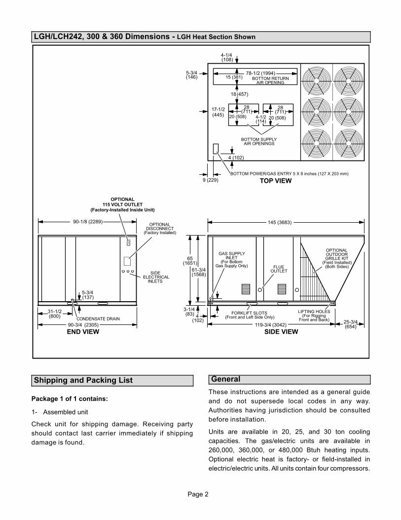
BOTTOM POWER/GAS ENTRY 5 X 8 inches (127 X 203 mm)
BOTTOM SUPPLYAIR OPENINGS
BOTTOM RETURNAIR OPENING
(108)
28(711)
28(711)
9 (229)
17-1/2
CONDENSATE DRAIN
(137)
(83)
GAS SUPPLYINLET
(For BottomGas Supply Only)
OPTIONALDISCONNECT
(Factory Installed)
SIDEELECTRICAL
INLETS
(102)
OPTIONALOUTDOORGRILLE KIT
(Field Installed)(Both Sides)FLUE
OUTLET
OPTIONAL115 VOLT OUTLET
(Factory-Installed Inside Unit)
5-3/4
90-3/4 (2305)
65(1651)
61-3/4(1568)
3-1/4
4
119-3/4 (3042)25-3/4(654)
145 (3683)
4-1/4
15 (381)78-1/2 (1994)5-3/4
(146)
18(457)
20 (508) 20 (508)4-1/2(114)
4 (102)
(445)
Shipping and Packing List
Package 1 of 1 contains:
1- Assembled unit
Check unit for shipping damage. Receiving party
should contact last carrier immediately if shipping
damage is found.
General
These instructions are intended as a general guide
and do not supersede local codes in any way.
Authorities having jurisdiction should be consulted
before installation.
Units are available in 20, 25, and 30 ton cooling
capacities. The gas/electric units are available in
260,000, 360,000, or 480,000 Btuh heating inputs.
Optional electric heat is factory- or field-installed in
electric/electric units. All units contain four compressors.
Page 3
LGH/LCH242 units are available with variable air volume
only. LGH/LCH300 and 360 are available in constant air
volume, variable air volume, or multi-staged air volume.
Refer to the 9th character of the model number to
determine type of blower:
B - Constant Air Volume
V - Variable Air Volume
M - Multi-Stage Air Volume
Units are available using R410A, an ozone-friendly HFC
refrigerant. Refer to the Cooling Start-Up section for
precautions when installing unit.
IMPORTANTSupply air VFD motor rotation is controlled independently from scroll compressor rotation. SeeBlower Operation and Adjustments section forcorrect compressor rotation. Compressor damage due to improper rotation is the responsibility ofthe installer.
Requirements
Use of this unit as a construction heater or air conditioner
is not recommended during any phase of construction.
Very low return air temperatures, harmful vapors and
operation of the unit with clogged or misplaced filters will
damage the unit.
If this unit has been used for heating or cooling of
buildings or structures under construction, the following
conditions must be met or the warranty will be void:
� The vent hood must be installed per these installation
instructions.
� A room thermostat must control the unit. The use of
fixed jumpers that will provide continuous heating or
cooling is not allowed.
� A pre-filter must be installed at the entry to the return
air duct.
� The return air duct must be provided and sealed to
the unit.
� Return air temperature range between 55°F (13°C)
and 80°F (27°C) must be maintained.
� Air filters must be replaced and pre-filters must be
removed upon construction completion.
� The input rate and temperature rise must be set per
the unit rating plate.
� The heat exchanger, components, duct system, air
filters and evaporator coil must be thoroughly
cleaned following final construction clean-up.
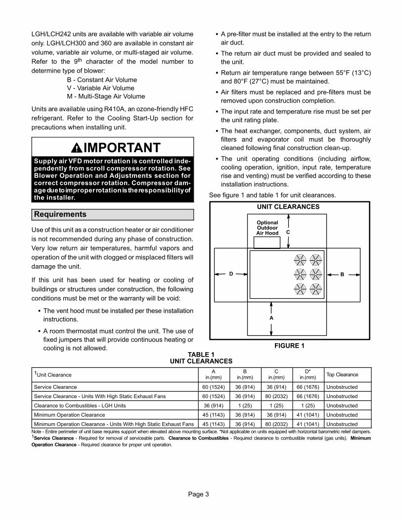
� The unit operating conditions (including airflow,
cooling operation, ignition, input rate, temperature
rise and venting) must be verified according to these
Minimum Operation Clearance - Units With High Static Exhaust Fans 45 (1143) 36 (914) 80 (2032) 41 (1041) Unobstructed
Note - Entire perimeter of unit base requires support when elevated above mounting surface. *Not applicable on units equipped with horizontal barometric relief dampers.1Service Clearance - Required for removal of serviceable parts. Clearance to Combustibles - Required clearance to combustible material (gas units). Minimum
Operation Clearance - Required clearance for proper unit operation.
Page 4
WARNINGElectric shock hazard and danger ofexplosion. Can cause injury, death orproduct or property damage. Turn offgas and electrical power to unit beforeperforming any maintenance orservicing operations on the unit. Followlighting instructions attached to unitwhen putting unit back into operationand after service or maintenance.
IMPORTANTThe Clean Air Act of 1990 bans the intentional ventingof refrigerant (CFC's and HCFC's) as of July 1, 1992.Approved methods of recovery, recycling or reclaiming must be followed. Fines and/or incarceration maybe levied for non-compliance.
CAUTIONAs with any mechanical equipment, contact withsharp sheet metal edges can result in personal injury.Take care while handling this equipment and weargloves and protective clothing.
NOTICERoof Damage!This system contains both refrigerant and oil. Somerubber roofing material may absorb oil, causing therubber to swell. Bubbles in the rubber roofingmaterial can cause leaks. Protect the roof surface toavoid exposure to refrigerant and oil during serviceand installation. Failure to follow this notice couldresult in damage to roof surface.
Unit Support
In downflow discharge installations, install the unit on a
non-combustible surface only. Unit may be installed on
combustible surfaces when used in horizontal discharge
applications or in downflow discharge applications when
installed on an S6CURB roof mounting frame.
Note - Securely fasten roof frame to roof per local codes.
CAUTIONTo reduce the likelihood of supply / return air bypassand promote a proper seal with the RTU, duct work /duct drops / diffuser assemblies must be supportedindependently to the building structure.
A-Downflow Discharge Application
Roof Mounting with S6CURB
1- The roof mounting frame must be installed, flashed
and sealed in accordance with the instructions
provided with the frame.
2- The roof mounting frame should be square and level
to 1/16” per linear foot (5mm per linear meter) in any
direction.
3- Duct must be attached to the roof mounting frame
and not to the unit; supply and return plenums must
be installed before setting the unit.
Installer's Roof Mounting Frame
Many types of roof frames can be used to install the unit
depending upon different roof structures. Items to keep
in mind when using the building frame or supports are:
1- The base is fully enclosed and insulated, so an
enclosed frame is not required.
2- The frames or supports must be constructed with
non-combustible materials and should be square and
level to 1/16” per linear foot (5mm per linear meter)
in any direction.
3- Frame or supports must be high enough to prevent any
form of moisture from entering unit. Recommended
minimum frame height is 14” (356mm).
4- Duct must be attached to the roof mounting frame
and not to the unit. Supply and return plenums must
be installed before setting the unit.
5- Units require support along all four sides of unit base.
Supports must be constructed of steel or suitably
treated wood materials.
Note-When installing a unit on a combustible surface for
downflow discharge applications, an S6CURB roof
mounting frame is required.
B-Horizontal Discharge Applications
1- Units installed in horizontal airflow applications must
use an LARMFH30/36 horizontal roof mounting
frame. The supply air duct connects to the horizontal
supply air opening on the LARMFH30/36. The return
air duct connects to the unit horizontal return air
opening. Refer to unit dimensions.
2- Specified installation clearances must be maintained
when installing units. Refer to figure 1.
3- Top of support slab should be approximately 4”
(102mm) above the finished grade and located so no
run-off water from higher ground can collect around
the unit.
4- Units require support along all four sides of unit base.
Supports must be constructed of steel or suitably
treated wood materials.
Page 5
Duct Connection
All exterior ducts, joints and openings in roof or building
walls must be insulated and weather-proofed with
flashing and sealing compounds in accordance with
applicable codes. Any duct passing through an
unconditioned space must be insulated.
CAUTIONIn downflow applications, do not drill or punch holesin base of unit. Leaking in roof may occur if unit base ispunctured.
Rigging Unit For Lifting
Rig unit for lifting by attaching four cables to holes in unit
base rail. See figure 2.
1- Detach wooden base protection before rigging.
2- Connect rigging to the unit base using both holes in
each corner.
3- All panels must be in place for rigging.
4- Place field‐provided H‐style pick in place just above
top edge of unit. Frame must be of adequate
strength and length. (H-style pick prevents damage
to unit.)
LGH
FIGURE 2
CAUTION - Do notwalk on unit.
IMPORTANT - ALL PANELS MUSTBE IN PLACE FOR RIGGING.
RIGGING
LIFTING POINT SHOULD BE DIRECTLYABOVE CENTER OF GRAVITY
3485 1581
Unit*Weight
Lbs. Kg.
*Maximum weight with all availablefactory-installed accessories.
LCH 15463409
Condensate Drains
Remove cap and make drain connection to the 1” N.P.T.
drain coupling provided on unit. A trap must be installed
between drain connection and an open vent for proper
condensate removal. See figure 3. It is sometimes
acceptable to drain condensate onto the roof or grade;
however, a tee should be fitted to the trap to direct
condensate downward. The condensate line must be
vented. Check local codes concerning condensate disposal.
Refer to pages 1 and 2 for condensate drain location.
Note - The drain pan is made with a glass reinforced
engineered plastic capable of withstanding typical joint
torque but can be damaged with excessive force. Tighten
pipe nipple hand tight and turn an additional quarter turn.
FIGURE 3
ÁÁÁÁÁÁÁÁÁÁÁÁÁÁÁÁÁÁÁÁÁÁÁÁÁÁÁÁ
UNIT
Minimum Pitch
1” (25 mm) per
10' (3 m) of line
MOUNTINGFRAME
OPEN VENT
CONDENSATE DRAIN CONNECTION
Note - Allow clearance to opendoors when installing condensate piping.
CAULK AROUND
CONDENSATE
COUPLING
Connect Gas Piping (Gas Units)
Before connecting piping, check with gas company or
authorities having jurisdiction for local code
requirements. When installing gas supply piping, length
of run from gas meter must be considered in determining
pipe size for 0.5” w.c. (.12kPa) maximum pressure drop.
Do not use supply pipe smaller than unit gas connection.
For natural gas units, operating pressure at the unit gas
connection must be a minimum of 4.7” w.c. (1.17kPa) and
a maximum of 10.5” (2.60kPa) w.c. For LP/propane gas
units, operating pressure at the unit gas connection must
be a minimum of 11” w.c. (2.74kPa) and a maximum of
13.5” w.c. (3.36kPa).
When making piping connections a drip leg should be
installed on vertical pipe runs to serve as a trap for
sediment or condensate. A 1/8” N.P.T. plugged tap is
located on gas valve for test gauge connection. Refer to
Heating Start-Up section for tap location. Install a ground
joint union between the gas control manifold and the main
manual shut-off valve. See figure 4 for gas supply piping
entering outside the unit. Figure 5 shows complete
bottom gas entry piping.
Page 6
Compounds used on threaded joints of gas piping shall be
resistant to the action of liquified petroleum gases.
TOGAS
SUPPLY
FIGURE 4
TO GASVALVE
MANUAL MAIN
SHUT-OFF VALVE
GAS PIPING
SUPPORT
GROUND
JOINT UNION
(REFER TO
LOCAL CODES) DRIP LEG
OUTSIDE OF UNIT GAS PIPING
DRIP LEG
MANUAL MAIN
SHUT-OFF VALVE
TO GASVALVE
GROUND
JOINT UNION
FIGURE 5
BOTTOM ENTRY GAS PIPING
CAP
EXISTINGSUPPLY
Pressure Test Gas Piping (Gas Units)
When pressure testing gas lines, the gas valve must
be disconnected and isolated. Gas valves can be
damaged if subjected to more than 0.5 psig (3.5kPa).
See figure 6.
Note-Codes may require that manual main shut-off
valve and union (furnished by installer) be installed in
gas line external to unit. Union must be of the ground
joint type.
After all connections have been made, check all piping
connections for gas leaks. Also check existing unit gas
connections up to the gas valve; loosening may occur
during installation. Use a leak detection solution or other
preferred means. Do not use matches candles or other
sources of ignition to check for gas leaks.
CAUTIONSome soaps used for leak detection are corrosive tocertain metals. Carefully rinse piping thoroughlyafter leak test has been completed. Do not usematches, candles, flame or othe sources of ignition tocheck for gas leaks.
GAS VALVE CAP
MANUAL MAIN
SHUT-OFF VALVE
FIGURE 6
PRESSURE TEST GAS LINE
WARNINGDanger of explosion. Can cause injuryor product or property damage. Do notuse matches, candles, flame or othersources of ignition to check for leaks.
Note-In case emergency shut down is required, turn off
the main manual shut-off valve and disconnect main
power to unit. These devices should be properly labeled
by the installer.
Page 7
High Altitude Derate
Locate the high altitude conversion sticker in the unit
literature bag. Fill out the conversion sticker and affix next
to the unit nameplate.
Refer to table 2 for high altitude adjustments.
TABLE 2HIGH ALTITUDE DERATE
Altitude Ft.* Gas Manifold Pressure
2000-4500 See Unit Nameplate
4500 And Above Derate 2% / 1000 Ft. Above Sea Level
*Units installed at 0-2000 feet do not need to be modified.
Note ‐ This is the only permissible derate for these units.
Factory-Installed Options
A-Economizer
The Unit Controller A55 controls economizer operation
and provides potentiometers to control minimum damper
position and enthalpy control adjustments. See the
economizer control settings section.
B-Intake Hood
Outdoor air hood is shipped folded down over the
horizontal supply air opening. The intake hood filters and
support brackets are shipped unassembled in the blower
compartment. Install as follows:
1- Remove left side from hood top panel. See figure 7.
REMOVE LEFT SIDE OF HOOD FROM UNIT
FIGURE 7
HOOD TOPPANEL
LEFTSIDE
LONGERFRONT
BRACKET
SHORTERFRONT
BRACKET
2- Remove and retain screws securing hood to unit.
3- Lift (rotate) the bottom of the hood top panel and
attach left side to hood top panel. See figure 8.
4- Secure sides of hood to unit mullions with retained
screws.
5- Caulk hinge opening on each end of air hood.
6- Install back filter bracket on unit division panel as
shown in figure 9.
OUTDOOR AIR HOOD
FIGURE 8
HOOD TOPPANEL
LIFT
CAULKBOTH ENDS
See Detail A
Detail A
LEFTSIDE
FIGURE 9
HOOD SIDE VIEW
HOOD TOP
UNITDIVISIONPANEL
BACK FILTERBRACKET
FRONT FILTERBRACKETS (2)
FILTERS
HOOD SIDE
7- Secure side seals to the hood sides as shown in
figure 10.
8- Install longer front filter bracket on hood top as shown
in figures 7 and 9. Insert four filters.
9- Slide fifth filter into back filter bracket and hold in
place at the top of the opening with the shorter front
bracket. Align holes on hood with bracket holes and
secure filter bracket with sheet metal screws.
Page 8
FIGURE 10
LEFTFILTERSEAL
RIGHTFILTERSEAL
FILTERS
Electrical Connections
POWER SUPPLY
Route field wiring in conduit between bottom power entry
disconnect. See figure 11. This does not supersede local
codes or authorities having jurisdiction.
SEALWATERTIGHT
RUN FIELDWIRING IN
FIELD PROVIDED CONDUIT
SIDE ENTRYKNOCKOUTS
BOTTOMPOWER ENTRY
OPTIONAL120V GFI
MAKE-UP BOX
FIGURE 11
FIELD WIRE ROUTING
WARNINGDo not apply power or close disconnect switch untilinstallation is complete. Refer to start-up directions.Refer closely to unit wiring diagram.
Refer to unit nameplate for minimum circuit ampacity
and maximum fuse size.
1- Units are factory-wired for 230/460/575 volt supply.
For 208V supply, remove the insulated terminal
cover from the 208V terminal on the control
transformer. Move the wire from the transformer
230V terminal to the 208V terminal. Place the
insulated terminal cover on the unused 230V
terminal.
2- Route power through the bottom power entry area
and connect to line side of unit disconnect, circuit
breaker or terminal block. See unit wiring diagram.
3- Units With Optional 120v GFCI Outlet -
Route and connect separate 120v wiring to GFCI
outlets which do not have factory-installed wiring.
Route field wiring in conduit between bottom power
entry and GFCI. See figure 11.
CONTROL WIRING
A-Thermostat Location
Room thermostat mounts vertically on a standard 2” X 4”
handy box or on any non-conductive flat surface.
Locate thermostat approximately 5 feet (1524mm)
above the floor in an area with good air circulation at
average temperature. Avoid locating the room
thermostat where it might be affected by:
-drafts or dead spots behind doors and in corners
-hot or cold air from ducts
-radiant heat from sun or appliances
-concealed pipes and chimneys
Page 9
B-Wire Routing
Route thermostat cable or wires from subbase through
knockout provided in unit. For thermostat wire runs up to
60 feet, use 18 gauge wire. For 60 to 90 feet runs, use 16
gauge wire.
IMPORTANT - Unless field thermostat wires are rated
for maximum unit voltage, they must be routed away
from line voltage wiring.
C-Wiring Connections
The Unit Controller will operate the unit from a thermostat
or zone sensor based on the System Mode. The default
System Mode is the thermostat mode. Refer to the Unit
Controller Setup Guide to change the System Mode.
1- Default Thermostat Mode -
The Unit Controller will operate two stages of heating
and cooling based on thermostat demands. Install
thermostat assembly in accordance with instructions
provided with thermostat. See figure 12 for field
wiring and wiring diagrams on unit.
IMPORTANT-Terminal connections at the wall plate or
subbase must be made securely. Loose control wire
connections may result in intermittent operation.
2- Zone Sensor Mode
The Unit Controller will operate heating and cooling
based on the Unit Controller internal setpoints and
the temperature from the A2 zone sensor. An optional
Network Control Panel (NCP) can also be used to
provide setpoints. A thermostat or return air sensor
can be used as a back-up mode. Make zone sensor
wiring connections as shown in figure 13.
Note - Install sensor and make communication wiring
connections as shown in literature provided with sensor.
FIGURE 12
FIELD WIRING WITH ELECTRONIC ANDELECTRO-MECHANICAL THERMOSTATS
(Thermostat Mode)
J262
C
10
11
12
P297J297A1
2B
3
4
5
6
7
8C
9
10
24 V POWER
W1
W2
P26
2
A55R
OCP
C
G
W1
W2
Y1
Y2
FIGURE 13
FIELD WIRING IN ZONE SENSOR MODE(Zone Sensor Mode)
A2 SENSOR
OUTPUTSSENSOR
SENSOR24VAC
R C
IAQ
HUMAI1 D01TMP D02
A57 UNIT CONTROLLER
J298
Page 10
CONTROL WIRING (continued)
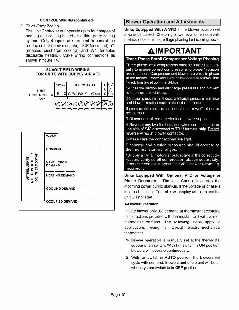
3- Third-Party Zoning -
The Unit Controller will operate up to four stages of
heating and cooling based on a third-party zoning
system. Only 4 inputs are required to control the
rooftop unit: G (blower enable), OCP (occupied), Y1
(enables discharge cooling) and W1 (enables
discharge heating). Make wiring connections as
shown in figure 14.
24VAC
COMMON
VENTILATION
HEATING DEMAND
COOLING DEMAND
OCCUPIED DEMAND
24 VOLT FIELD WIRINGFOR UNITS WITH SUPPLY AIR VFD
24VAC
R C
THERMOSTAT
G W1 W2 Y1 Y2 OCP
G
L
O
DEMAND
UNITCONTROLLER
J297
Blower Operation and Adjustments
Units Equipped With A VFD - The blower rotation will
always be correct. Checking blower rotation is not a valid
method of determining voltage phasing for incoming power.
IMPORTANTThree Phase Scroll Compressor Voltage Phasing
Three phase scroll compressors must be phased sequentially to ensure correct compressor and blower* rotationand operation. Compressor and blower are wired in phaseat the factory. Power wires are color-coded as follows: line1-red, line 2-yellow, line 3-blue.
1-Observe suction and discharge pressures and blower*rotation on unit start-up.
2-Suction pressure must drop, discharge pressure must riseand blower* rotation must match rotation marking.
If pressure differential is not observed or blower* rotation isnot correct:
3-Disconnect all remote electrical power supplies.
4-Reverse any two field-installed wires connected to theline side of S48 disconnect or TB13 terminal strip. Do notreverse wires at blower contactor.
5-Make sure the connections are tight.
Discharge and suction pressures should operate attheir normal start‐up ranges.
*Supply air VFD motors should rotate in the correct direction; verify scroll compressor rotation separately.Contact technical support if the VFD blower is rotatingincorrectly.
Units Equipped With Optional VFD or Voltage or
Phase Detection - The Unit Controller checks the
incoming power during start-up. If the voltage or phase is
incorrect, the Unit Controller will display an alarm and the
unit will not start.
A-Blower Operation
Initiate blower only (G) demand at thermostat according
to instructions provided with thermostat. Unit will cycle on
thermostat demand. The following steps apply to
applications using a typical electro-mechanical
thermostat.
1- Blower operation is manually set at the thermostat
subbase fan switch. With fan switch in ON position,
blowers will operate continuously.
2- With fan switch in AUTO position, the blowers will
cycle with demand. Blowers and entire unit will be off
when system switch is in OFF position.
Page 11
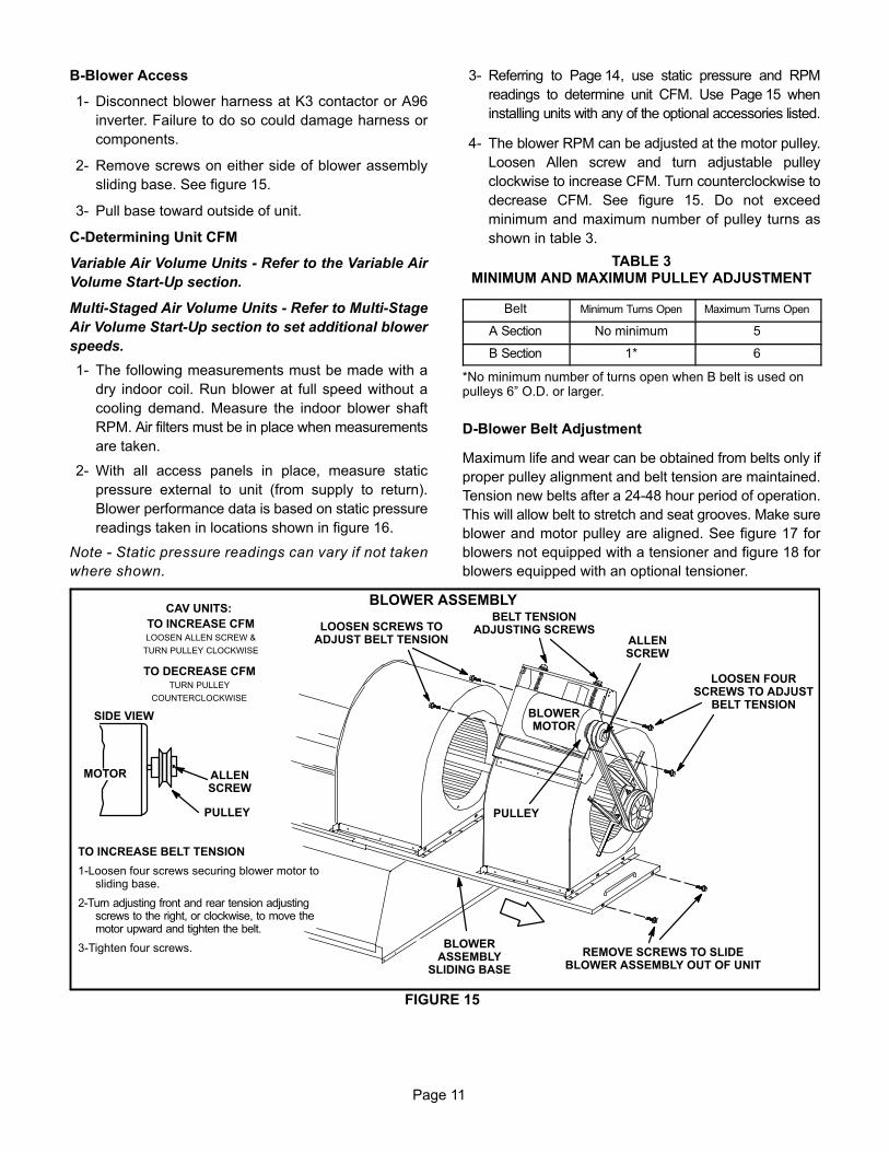
B-Blower Access
1- Disconnect blower harness at K3 contactor or A96
inverter. Failure to do so could damage harness or
components.
2- Remove screws on either side of blower assembly
sliding base. See figure 15.
3- Pull base toward outside of unit.
C-Determining Unit CFM
Variable Air Volume Units - Refer to the Variable Air
Volume Start-Up section.
Multi-Staged Air Volume Units - Refer to Multi-Stage
Air Volume Start-Up section to set additional blower
speeds.
1- The following measurements must be made with a
dry indoor coil. Run blower at full speed without a
cooling demand. Measure the indoor blower shaft
RPM. Air filters must be in place when measurements
are taken.
2- With all access panels in place, measure static
pressure external to unit (from supply to return).
Blower performance data is based on static pressure
readings taken in locations shown in figure 16.
Note - Static pressure readings can vary if not taken
where shown.
3- Referring to Page 14, use static pressure and RPM
readings to determine unit CFM. Use Page 15 when
installing units with any of the optional accessories listed.
4- The blower RPM can be adjusted at the motor pulley.
Loosen Allen screw and turn adjustable pulley
clockwise to increase CFM. Turn counterclockwise to
decrease CFM. See figure 15. Do not exceed
minimum and maximum number of pulley turns as
shown in table 3.
TABLE 3MINIMUM AND MAXIMUM PULLEY ADJUSTMENT
Belt Minimum Turns Open Maximum Turns Open
A Section No minimum 5
B Section 1* 6
*No minimum number of turns open when B belt is used onpulleys 6” O.D. or larger.
D-Blower Belt Adjustment
Maximum life and wear can be obtained from belts only if
proper pulley alignment and belt tension are maintained.
Tension new belts after a 24-48 hour period of operation.
This will allow belt to stretch and seat grooves. Make sure
blower and motor pulley are aligned. See figure 17 for
blowers not equipped with a tensioner and figure 18 for
blowers equipped with an optional tensioner.
BLOWER ASSEMBLY
FIGURE 15
TO INCREASE BELT TENSION
1-Loosen four screws securing blower motor tosliding base.
2-Turn adjusting front and rear tension adjustingscrews to the right, or clockwise, to move themotor upward and tighten the belt.
3-Tighten four screws.
TO INCREASE CFMLOOSEN ALLEN SCREW &
TURN PULLEY CLOCKWISE
TO DECREASE CFMTURN PULLEY
COUNTERCLOCKWISE
LOOSEN FOURSCREWS TO ADJUST
BELT TENSIONBLOWERMOTOR
REMOVE SCREWS TO SLIDEBLOWER ASSEMBLY OUT OF UNIT
LOOSEN SCREWS TOADJUST BELT TENSION
PULLEY
ALLENSCREW
BELT TENSIONADJUSTING SCREWS
BLOWERASSEMBLY
SLIDING BASE
PULLEY
MOTOR ALLENSCREW
SIDE VIEW
CAV UNITS:
Page 12
Blowers Without Belt Tensioner
1- Loosen four screws securing blower motor to sliding
base. See figure 15.
2- To increase belt tension -
Turn belt tension adjusting screw to the right, or
clockwise, to tighten the belt. This increases the
distance between the blower motor and the blower
housing.
To loosen belt tension -
Turn the adjusting screw to the left, or
counterclockwise to loosen belt tension.
3- Tighten four screws securing blower motor to sliding
base once adjustments have been made.
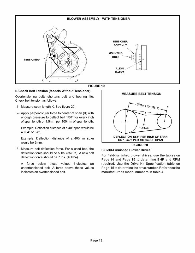
Blowers Equipped With Belt Tensioner
1- Loosen the bolt in the center of the tensioner. See
figure 19.
2- Place belt over all three pulleys. Tensioner pulley
must be oriented toward blower, not motor.
3- Using a 15/16” wrench on the tensioner body nut, turn
the tensioner nut until marks align (3rd mark).
4- Hold the tensioner with marks aligned and tighten the
bolt to 22 ft.lbs. using the 9/16” wrench.
5- If tensioner pulley is past 7 o'clock when secured,
The distance between the motor and blower pulleys
need to be increased. Refer to the steps in figure 15
to increase belt tension.
FIGURE 16
LOCATION OF STATIC PRESSURE READINGS
SUPPLY AIRREADINGLOCATION
SUPPLYRE
TURN
INSTALLATIONS WITH DUCTWORK
SUPPLY RETURN
INSTALLATIONS WITH CEILING DIFFUSERS
MAINDUCT RUN
FIRST BRANCHOFF OF MAIN RUN
DIFFUSER
ROOFTOP UNIT ROOFTOP UNIT
SUPPLY AIRREADINGLOCATION
RETURN AIRREADING LOCATION
RETURN AIRREADINGLOCATION
FIGURE 17
PULLEY ALIGNMENT - NO TENSIONER
BELTBLOWERPULLEY
MOTORPULLEY
NOT ALIGNED
ALIGNED
BELTBLOWERPULLEY
MOTORPULLEY
NOT ALIGNED
ALIGNED
TENSIONER
PULLEY ALIGNMENT - WITH TENSIONER
FIGURE 18
Page 13
BLOWER ASSEMBLY - WITH TENSIONER
FIGURE 19
TENSIONER
TENSIONER
BODY NUT
MOUNTING
BOLT
ALIGN
MARKS
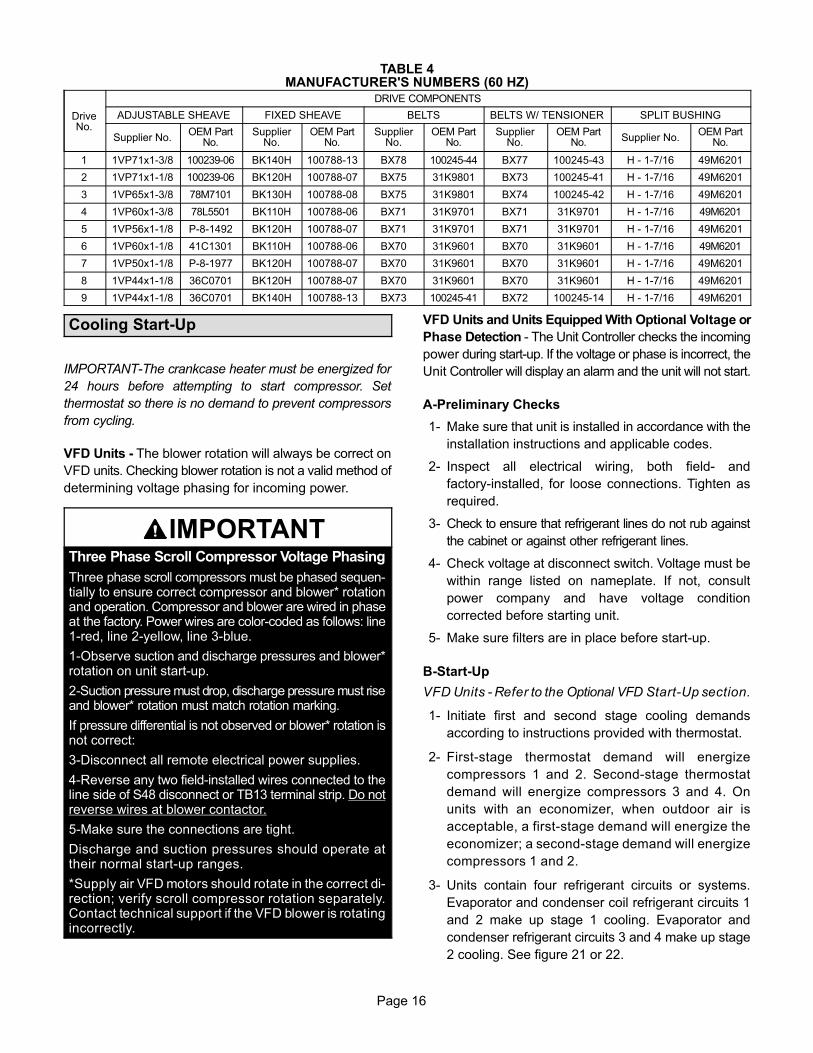
E-Check Belt Tension (Models Without Tensioner)
Overtensioning belts shortens belt and bearing life.
Check belt tension as follows:
1- Measure span length X. See figure 20.
2- Apply perpendicular force to center of span (X) with
enough pressure to deflect belt 1/64” for every inch
of span length or 1.5mm per 100mm of span length.
Example: Deflection distance of a 40” span would be
40/64” or 5/8”.
Example: Deflection distance of a 400mm span
would be 6mm.
3- Measure belt deflection force. For a used belt, the
deflection force should be 5 lbs. (35kPa). A new belt
deflection force should be 7 lbs. (48kPa).
A force below these values indicates an
undertensioned belt. A force above these values
indicates an overtensioned belt.
MEASURE BELT TENSION
FIGURE 20
DEFLECTION 1/64” PER INCH OF SPANOR 1.5mm PER 100mm OF SPAN
FORCE
F-Field-Furnished Blower Drives
For field-furnished blower drives, use the tables on
Page 14 and Page 15 to determine BHP and RPM
required. Use the Drive Kit Specification table on
Page 15 to determine the drive number. Reference the
manufacturer's model numbers in table 4.
Page 14
BLO
WE
R D
ATA
BLO
WE
R T
AB
LE IN
CLU
DE
S R
ES
ISTA
NC
E F
OR
BA
SE
UN
IT O
NLY
WIT
H D
RY
IND
OO
R C
OIL
& A
IR F
ILTE
RS
IN P
LAC
E
FOR
ALL
UN
ITS
AD
D:
1 - W
et in
door
coi
l air
resi
stan
ce o
f sel
ecte
d un
it.
2 - A
ny fa
ctor
y in
stal
led
optio
ns a
ir re
sist
ance
(ele
ctric
hea
t, ec
onom
izer
, etc
.) 3
- Any
fiel
d in
stal
led
acce
ssor
ies
air r
esis
tanc
e (e
lect
ric h
eat,
duct
resi
stan
ce, d
iffus
er, e
tc.)
Then
det
erm
ine
from
blo
wer
tabl
e bl
ower
mot
or o
utpu
t and
driv
e re
quire
d.
See
pag
e 15
for w
et c
oil a
nd o
ptio
n/ac
cess
ory
air r
esis
tanc
e da
ta.
See
pag
e 15
for f
acto
ry in
stal
led
driv
e ki
t spe
cific
atio
ns.
MIN
IMU
M A
IR V
OLU
ME
REQ
UIR
ED F
OR
USE
WIT
H O
PTIO
NA
L EL
ECTR
IC H
EAT
All
units
requ
ire 1
0,50
0 cf
m m
inim
um a
ir w
ith e
lect
ric h
eat.
Air
Volu
me
cfm
TOTA
L ST
ATIC
PR
ESSU
RE
- In.
w.g
.0.
200.
400.
600.
801.
001.
201.
401.
601.
802.
002.
202.
402.
60
RPM
BH
PR
PMB
HP
RPM
BH
PR
PMB
HP
RPM
BH
PR
PMB
HP
RPM
BH
PR
PMB
HP
RPM
BH
PR
PMB
HP
RPM
BH
PR
PMB
HP
RPM
BH
P
4000
372
0.26
433
0.65
497
0.99
565
1.27
630
1.54
687
1.79
738
2.04
784
2.30
824
2.56
861
2.82
897
3.10
932
3.40
- - -
- - -
4500
382
0.41
441
0.79
506
1.12
574
1.41
638
1.69
694
1.95
744
2.22
790
2.50
831
2.77
868
3.05
903
3.35
938
3.66
974
4.01
5000
392
0.56
451
0.93
516
1.25
584
1.55
646
1.85
702
2.12
751
2.41
796
2.70
837
3.00
874
3.30
909
3.61
944
3.93
980
4.30
5500
402
0.73
462
1.08
527
1.40
594
1.72
655
2.02
710
2.31
758
2.61
802
2.92
843
3.24
880
3.56
916
3.88
951
4.22
987
4.60
6000
414
0.89
473
1.24
539
1.56
605
1.90
665
2.21
718
2.51
766
2.83
809
3.16
850
3.51
887
3.84
922
4.18
957
4.52
994
4.91
6500
426
1.07
486
1.41
551
1.74
616
2.10
675
2.42
727
2.73
774
3.07
817
3.43
857
3.80
894
4.15
929
4.49
964
4.85
1001
5.24
7000
439
1.26
499
1.60
565
1.93
628
2.31
685
2.64
737
2.97
782
3.34
825
3.72
864
4.11
901
4.48
937
4.83
971
5.19
1008
5.59
7500
453
1.46
513
1.79
579
2.14
641
2.55
696
2.88
747
3.24
792
3.63
833
4.04
872
4.45
909
4.83
945
5.20
979
5.56
1016
5.97
8000
467
1.66
528
2.00
593
2.38
653
2.81
708
3.15
757
3.53
801
3.95
843
4.39
881
4.82
918
5.22
953
5.59
988
5.96
1025
6.37
8500
483
1.88
544
2.22
608
2.65
667
3.10
720
3.44
768
3.85
812
4.30
852
4.78
890
5.22
927
5.63
962
6.01
997
6.39
1034
6.81
9000
499
2.11
561
2.47
624
2.95
681
3.41
733
3.76
780
4.20
823
4.69
862
5.19
900
5.65
936
6.07
972
6.46
1007
6.85
1044
7.28
9500
516
2.36
578
2.75
640
3.26
696
3.73
746
4.10
792
4.58
834
5.11
873
5.64
910
6.12
946
6.54
982
6.93
1018
7.34
1055
7.78
10,0
0053
42.
6459
63.
0665
73.
6071
14.
0776
04.
4880
55.
0084
55.
5788
46.
1292
16.
6195
77.
0399
27.
4310
287.
8610
668.
3210
,500
553
2.93
615
3.39
674
3.95
727
4.44
775
4.90
817
5.46
857
6.06
895
6.62
932
7.12
967
7.55
1003
7.96
1039
8.40
1077
8.89
11,0
0057
23.
2463
43.
7469
24.
3174
44.
8378
95.
3583
05.
9586
96.
5890
77.
1694
37.
6597
88.
0910
138.
5110
508.
9810
899.
4911
,500
592
3.58
653
4.12
711
4.70
760
5.27
803
5.85
843
6.49
881
7.13
918
7.71
954
8.21
989
8.65
1025
9.10
1062
9.59
1101
10.1
212
,000
613
3.95
674
4.53
729
5.14
776
5.75
818
6.39
857
7.06
894
7.71
930
8.30
965
8.80
1000
9.25
1036
9.71
1073
10.2
211
1210
.77
12,5
0063
54.
3769
54.
9874
85.
6279
26.
2983
26.
9887
07.
6790
68.
3394
18.
9197
69.
4210
119.
8710
4810
.35
1085
10.8
611
2411
.42
13,0
0065
74.
8371
55.
5076
66.
1880
86.
8984
77.
6188
38.
3291
88.
9895
39.
5698
810
.06
1023
10.5
210
5911
.00
- - -
- - -
- - -
- - -
13,5
0068
05.
3573
66.
0678
46.
7882
47.
5386
18.
2989
69.
0093
09.
6696
510
.24
1000
10.7
410
3511
.20
- - -
- - -
- - -
- - -
- - -
- - -
14,0
0070
45.
9275
76.
6780
17.
4483
98.
2387
59.
0090
99.
7294
310
.38
977
10.9
410
1211
.43
- - -
- - -
- - -
- - -
- - -
- - -
- - -
- - -
14,5
0072
76.
5577
77.
3481
88.
1685
48.
9788
99.
7592
210
.48
955
11.1
2- -
-- -
-- -
-- -
-- -
-- -
-- -
-- -
-- -
-- -
-- -
-- -
-15
,000
750
7.23
797
8.07
834
8.92
868
9.75
902
10.5
493
511
.26
- - -
- - -
- - -
- - -
- - -
- - -
- - -
- - -
- - -
- - -
- - -
- - -
- - -
- - -
Page 15
FACTORY INSTALLED OPTIONS/FIELD INSTALLED ACCESSORY AIR RESISTANCE
Air Volume
cfm
Wet Indoor
Coil
Gas Heat ExchangerElectric
heat EconomizerFilters
Horizontal Roof CurbStandard
HeatMedium
HeatHigh Heat MERV 8 MERV 13
in. w.g. in. w.g. in. w.g. in. w.g. in. w.g. in. w.g. in. w.g. in. w.g. in. w.g.4000 0.07 0.08 0.08 0.11 0.01 0.00 0.00 0.00 0.04
BLOWER DATAFACTORY INSTALLED BELT DRIVE KIT SPECIFICATIONS
Motor Efficiency Nominal hp
Maximum hp
Drive Kit Number RPM Range
Standard 5 5.75 5 660 - 810
Standard 5 5.75 6 770 - 965
Standard 5 5.75 7 570 - 720
Standard 5 5.75 8 480 - 630
Standard 5 5.75 9 410 - 535
Standard 7.5 8.63 3 715 - 880
Standard 7.5 8.63 4 770 - 965
Standard 10 11.50 1 740 - 895
Standard 10 11.50 2 870 - 1045
NOTESUsing total air volume and system static pressure requirements determine from blower performance tables rpm and motor output required. Maximum usable output of motors furnished are shown. In Canada, nominal motor output is also maximum usable motor output. If motors of comparable output are used, be sure to keep within the service factor limitations outlined on the motor nameplate.For VFD applications, nominal motor output is also maximum usable motor output.
IMPORTANT-The crankcase heater must be energized for
24 hours before attempting to start compressor. Set
thermostat so there is no demand to prevent compressors
from cycling.
VFD Units - The blower rotation will always be correct on
VFD units. Checking blower rotation is not a valid method of
determining voltage phasing for incoming power.
IMPORTANTThree Phase Scroll Compressor Voltage Phasing
Three phase scroll compressors must be phased sequentially to ensure correct compressor and blower* rotationand operation. Compressor and blower are wired in phaseat the factory. Power wires are color-coded as follows: line1-red, line 2-yellow, line 3-blue.
1-Observe suction and discharge pressures and blower*rotation on unit start-up.
2-Suction pressure must drop, discharge pressure must riseand blower* rotation must match rotation marking.
If pressure differential is not observed or blower* rotation isnot correct:
3-Disconnect all remote electrical power supplies.
4-Reverse any two field-installed wires connected to theline side of S48 disconnect or TB13 terminal strip. Do notreverse wires at blower contactor.
5-Make sure the connections are tight.
Discharge and suction pressures should operate attheir normal start‐up ranges.
*Supply air VFD motors should rotate in the correct direction; verify scroll compressor rotation separately.Contact technical support if the VFD blower is rotatingincorrectly.
VFD Units and Units Equipped With Optional Voltage or
Phase Detection - The Unit Controller checks the incoming
power during start-up. If the voltage or phase is incorrect, the
Unit Controller will display an alarm and the unit will not start.
A-Preliminary Checks
1- Make sure that unit is installed in accordance with the
installation instructions and applicable codes.
2- Inspect all electrical wiring, both field‐ and
factory‐installed, for loose connections. Tighten as
required.
3- Check to ensure that refrigerant lines do not rub against
the cabinet or against other refrigerant lines.
4- Check voltage at disconnect switch. Voltage must be
within range listed on nameplate. If not, consult
power company and have voltage condition
corrected before starting unit.
5- Make sure filters are in place before start‐up.
B-Start-Up
VFD Units - Refer to the Optional VFD Start-Up section.
1- Initiate first and second stage cooling demands
according to instructions provided with thermostat.
2- First-stage thermostat demand will energize
compressors 1 and 2. Second-stage thermostat
demand will energize compressors 3 and 4. On
units with an economizer, when outdoor air is
acceptable, a first-stage demand will energize the
economizer; a second-stage demand will energize
compressors 1 and 2.
3- Units contain four refrigerant circuits or systems.
Evaporator and condenser coil refrigerant circuits 1
and 2 make up stage 1 cooling. Evaporator and
condenser refrigerant circuits 3 and 4 make up stage
2 cooling. See figure 21 or 22.
Page 17
4- Each refrigerant circuit is separately charged with
R410A refrigerant. See unit rating plate for correct
amount of charge.
5- Refer to Cooling Operation and Adjustment section for
proper method to check refrigerant charge.
EVAPORATORCOIL
STAGE 1CONDENSER COIL
FIGURE 21
STAGE 2CONDENSER COIL
STAGE 1EVAPORATOR
COIL
STAGE 2EVAPORATOR
COIL
CONSTANT AIR VOLUME SUPPLY AIR REFRIGERANT CIRCUITS
VARIABLE AND STAGED SUPPLY AIR UNIT REFRIGERANT CIRCUITS
CONDENSERCOIL
FIGURE 22
CONDENSERCOIL
EVAPORATORCOIL
EVAPORATORCOIL
CIRCUIT 3
CIRCUIT 4
Page 18
C-R410A Refrigerant
Units charged with R410A refrigerant operate at much
higher pressures than R22. The expansion valve and
liquid line drier provided with the unit are approved for use
with R410A. Do not replace them with components
designed for use with R22.
R410A refrigerant is stored in a pink cylinder.
IMPORTANTMineral oils are not compatible with R410A. If oil mustbe added, it must be a polyol ester oil.
Manifold gauge sets used with systems charged with
R410A refrigerant must be capable of handling the higher
system operating pressures. The gauges should be rated
for use with pressures of 0-800 on the high side and a low
side of 30” vacuum to 250 psi with dampened speed to
500 psi. Gauge hoses must be rated for use at up to 800
psi of pressure with a 4000 psi burst rating.
D-Refrigerant Charge and Check
WARNING-Do not exceed nameplate charge under
any condition.
This unit is factory charged and should require no further
adjustment. If the system requires additional refrigerant,
reclaim the charge, evacuate the system, and add
required nameplate charge.
Note - System charging is not recommended below 60�F
(15�C). In temperatures below 60�F (15�C), the charge
must be weighed into the system.
If weighing facilities are not available, or to check the
charge, use the following procedure:
IMPORTANT - Charge unit in standard cooling mode.
1- Make sure outdoor coil is clean. Attach gauge
manifolds and operate unit at full CFM in cooling
mode with economizer disabled until system
stabilizes (approximately five minutes). Make sure all
outdoor air dampers are closed.
2- Check each system separately with all stages
operating. Compare the normal operating pressures
(see tables 5 - 9) to the pressures obtained from the
gauges. Check unit components if there are
significant differences.
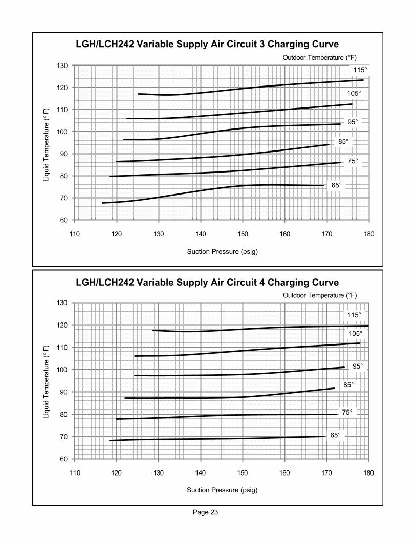
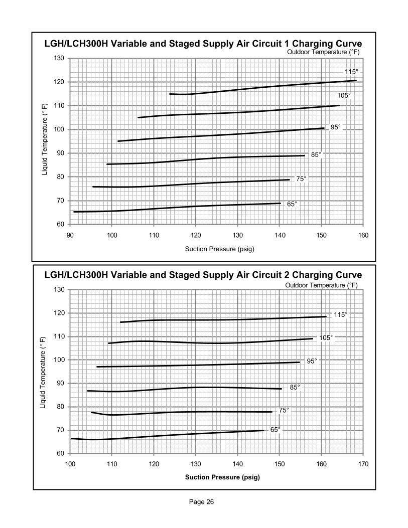
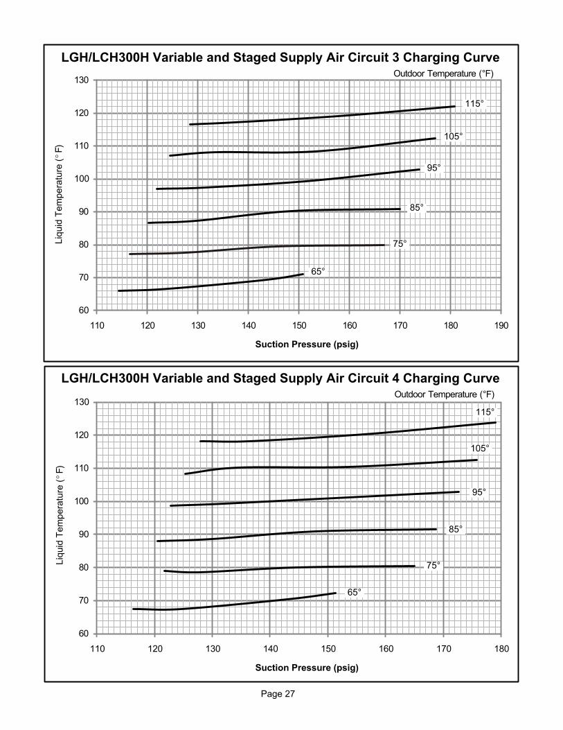
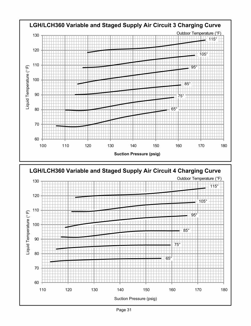
3- Measure the outdoor ambient temperature and the
suction pressure. Refer to the appropriate circuit
charging curve to determine a target liquid
temperature.
Note - Pressures are listed for sea level applications.
4- Use the same thermometer to accurately measure the
liquid temperature (near the liquid service tap).
� If measured liquid temperature is higher than
the target liquid temperature, add refrigerant to
the system.
� If measured liquid temperature is lower than
the target liquid temperature, recover some
refrigerant from the system.
5- Add or remove charge in increments. Allow the
system to stabilize each time refrigerant is added or
removed.
6- Continue the process until measured liquid
temperature agrees with the target liquid
temperature. Do not go below the target liquid
temperature when adjusting charge. Note that
suction pressure can change as charge is adjusted.
7- Example LGH/LCH242H Circuit 1: At 95°F outdoor
ambient and a measured suction pressure of
130psig, the target liquid temperature is 98°F. For a
measured liquid temperature of 106°F, add charge in
increments until measured liquid temperature agrees
with the target liquid temperature.
Page 19
TABLE 5
LGH/LCH242 VAV Normal Operating Pressures
Outdoor Coil Entering Air Temperature
65 °F 75 °F 85 °F 95 °F 105 °F 115 °FSuct(psig)
Disc(psig)
Suct(psig)
Disc(psig)
Suct(psig)
Disc(psig)
Suct(psig)
Disc(psig)
Suct(psig)
Disc(psig)
Suct(psig)
Disc(psig)
Circuit 1
97 232 99 268 102 309 104 358 104 407 109 465
106 234 109 269 111 310 113 358 116 409 118 467
129 241 126 275 129 318 132 363 134 416 139 469
148 247 152 283 148 325 152 372 154 422 158 475
Circuit 2
103 225 104 263 107 303 108 353 108 407 113 471
110 227 113 262 116 305 117 354 119 407 122 473
133 236 130 267 133 313 135 358 138 414 141 475
151 243 155 275 152 319 155 366 158 420 160 478
Circuit 3
117 237 118 273 120 321 122 370 123 422 125 478
126 239 128 272 130 322 131 371 133 422 135 479
149 245 148 280 149 328 151 376 153 430 157 483
169 254 173 288 170 335 173 383 176 435 179 485
Circuit 3
118 234 120 271 122 313 124 361 124 409 129 471
127 236 129 270 131 317 133 364 136 411 139 475
150 244 149 277 150 325 153 370 156 421 159 476
169 254 172 289 172 331 174 379 178 428 180 482
TABLE 6
LGH/LCH300H CAV Normal Operating Pressures
Outdoor Coil Entering Air Temperature
65 °F 75 °F 85 °F 95 °F 105 °F 115 °FSuct(psig)
Disc(psig)
Suct(psig)
Disc(psig)
Suct(psig)
Disc(psig)
Suct(psig)
Disc(psig)
Suct(psig)
Disc(psig)
Suct(psig)
Disc(psig)
Circuit 1
103 243 105 282 108 327 110 377 112 429 114 489
112 244 114 283 116 327 119 378 121 432 124 489
131 251 133 289 136 334 138 383 140 434 143 496
147 259 154 299 157 342 160 390 163 444 167 499
Circuit 2
105 251 108 291 109 337 112 391 113 456 115 552
114 254 116 293 118 339 120 392 122 453 125 537
135 258 137 297 138 343 140 394 142 449 144 520
150 268 158 306 161 351 165 399 167 455 168 513
Circuit 3
107 237 109 277 111 323 112 379 114 434 117 494
116 239 118 280 120 324 122 377 124 432 126 495
136 245 138 285 140 330 142 381 144 431 146 499
151 250 159 295 161 339 164 387 166 443 169 502
Circuit 4
102 252 105 293 108 328 110 393 112 449 114 523
109 256 114 297 116 345 118 399 121 455 123 529
130 261 133 303 135 348 137 402 139 456 141 525
148 266 156 312 158 358 161 407 163 464 166 526
Page 20
TABLE 7
LGH/LCH300H Variable and Staged Supply Air Normal Operating Pressures
Outdoor Coil Entering Air Temperature
65 °F 75 °F 85 °F 95 °F 105 °F 115 °FSuct(psig)
Disc(psig)
Suct(psig)
Disc(psig)
Suct(psig)
Disc(psig)
Suct(psig)
Disc(psig)
Suct(psig)
Disc(psig)
Suct(psig)
Disc(psig)
Circuit 1
91 273 96 304 99 354 102 400 106 451 114 505
102 278 107 315 110 356 112 404 114 455 119 509
120 287 124 323 127 368 130 409 132 460 138 522
140 297 142 332 146 372 151 422 154 467 158 525
Circuit 2
100 264 105 306 104 345 107 393 109 450 112 514
107 269 111 306 113 348 116 395 118 452 121 515
125 276 128 312 131 357 134 399 137 451 140 517
146 284 148 318 151 359 155 410 158 456 161 520
Circuit 3
114 279 117 317 120 366 122 417 125 475 129 539
124 282 128 323 130 370 132 420 134 478 137 539
144 294 146 332 149 378 151 423 153 478 158 542
151 298 167 339 170 383 174 436 177 484 181 546
Circuit 4
116 268 122 311 121 349 123 397 125 452 128 508
125 270 128 309 130 353 132 400 135 454 136 512
143 283 145 319 148 364 151 405 154 455 156 519
151 288 165 327 169 369 173 419 176 466 179 525
TABLE 8
LGH/LCH360 CAV Normal Operating Pressures
Outdoor Coil Entering Air Temperature
65 °F 75 °F 85 °F 95 °F 105 °F 115 °FSuct(psig)
Disc(psig)
Suct(psig)
Disc(psig)
Suct(psig)
Disc(psig)
Suct(psig)
Disc(psig)
Suct(psig)
Disc(psig)
Suct(psig)
Disc(psig)
Circuit 1
96 254 102 295 105 338 107 393 107 446 111 511
106 260 111 298 112 345 115 395 117 448 120 508
126 267 131 307 133 356 135 399 137 456 140 511
144 275 151 318 154 360 157 412 159 462 162 525
Circuit 2
98 255 104 301 106 349 108 405 109 477 113 563
108 262 112 305 114 353 116 408 118 468 121 547
129 272 133 313 135 363 136 407 138 468 141 532
146 279 154 326 156 369 159 423 160 474 162 540
Circuit 3
99 253 108 299 110 345 112 400 113 452 116 525
110 256 116 302 118 348 120 398 122 452 125 518
132 266 137 314 139 362 140 405 142 460 145 522
148 281 156 326 159 372 162 425 164 478 166 537
Circuit 4
102 258 104 313 106 359 110 414 110 471 114 544
112 267 112 320 115 366 116 418 118 471 121 539
130 287 133 330 136 378 137 422 138 479 142 541
148 298 153 345 157 392 159 444 162 497 163 558
Page 21
TABLE 9
LGH/LCH360 Variable and Staged Supply Air Normal Operating Pressures
Outdoor Coil Entering Air Temperature
65 °F 75 °F 85 °F 95 °F 105 °F 115 °FSuct(psig)
Disc(psig)
Suct(psig)
Disc(psig)
Suct(psig)
Disc(psig)
Suct(psig)
Disc(psig)
Suct(psig)
Disc(psig)
Suct(psig)
Disc(psig)
Circuit 1
88 252 90 301 97 351 98 388 102 450 104 516
100 255 102 305 105 355 107 403 111 456 113 523
115 268 119 314 123 361 125 403 129 463 129 527
133 282 137 327 140 371 144 425 147 473 152 544
Circuit 2
97 257 100 303 102 349 104 385 106 447 107 524
104 256 107 305 110 353 112 399 115 451 117 523
121 270 125 313 128 355 130 397 134 454 134 521
135 280 140 322 145 364 148 416 151 464 154 535
Circuit 3
106 272 110 319 115 366 116 404 118 469 120 537
118 266 120 320 123 375 124 422 127 472 130 545
137 285 139 332 142 379 144 418 147 477 148 544
155 294 158 344 161 393 164 443 167 492 172 563
Circuit 4
113 258 115 304 117 349 119 384 121 445 123 511
119 253 122 305 125 356 128 399 130 450 132 520
138 280 142 320 145 359 147 400 149 456 151 521
156 293 159 333 163 374 166 424 169 471 173 539
Page 22
60
70
80
90
100
110
120
130
90 100 110 120 130 140 150 160
Suction Pressure (psig)
Outdoor Temperature (°F)
115°
105°
95°
85°
75°
65°
LGH/LCH242 Variable Supply Air Circuit 1 Charging CurveLiq
uid
Tem
pera
ture
(°F
)
60
70
80
90
100
110
120
130
90 100 110 120 130 140 150 160
Suction Pressure (psig)
Outdoor Temperature (°F)
115°
105°
95°
85°
75°
65°
LGH/LCH242 Variable Supply Air Circuit 2 Charging Curve
Liq
uid
Tem
pera
ture
(°F
)
Page 23
60
70
80
90
100
110
120
130
110 120 130 140 150 160 170 180
Suction Pressure (psig)
Outdoor Temperature (°F)
115°
105°
95°
85°
75°
65°
LGH/LCH242 Variable Supply Air Circuit 3 Charging CurveLiq
uid
Tem
pera
ture
(°F
)
60
70
80
90
100
110
120
130
110 120 130 140 150 160 170 180
Suction Pressure (psig)
Outdoor Temperature (°F)
115°
105°
95°
85°
75°
65°
LGH/LCH242 Variable Supply Air Circuit 4 Charging Curve
Liq
uid
Tem
pera
ture
(°F
)
Page 24
110 120 130 140 150 160 170100
60
70
80
90
100
110
120
130
Suction Pressure (psig)
115°
105°
95°
85°
75°
65°
Outdoor Temperature (°F)
Liq
uid
Tem
pera
ture
(°F
)LGH/LCH300H CAV Circuit 1 Charging Curve
60
70
80
90
100
110
120
130
100 110 120 130 140 150 160 170
Suction Pressure (psig)
115°
105°
95°
85°
75°
65°
Outdoor Temperature (°F)
Liq
uid
Tem
pera
ture
(°F
)
LGH/LCH300H CAV Circuit 2 Charging Curve
Page 25
60
70
80
90
100
110
120
130
100 110 120 130 140 150 160 170
115°
105°
95°
85°
75°
65°
Suction Pressure (psig)
Outdoor Temperature (°F)
Liq
uid
Tem
pera
ture
(°F
)LGH/LCH300H CAV Circuit 3 Charging Curve
60
70
80
90
100
110
120
130
100 110 120 130 140 150 160 170
Suction Pressure (psig)
Liq
uid
Tem
pera
ture
(°F
)
115°
105°
95°
85°
75°
65°
Outdoor Temperature (°F)
LGH/LCH300H CAV Circuit 4 Charging Curve
Page 26
60
70
80
90
100
110
120
130
90 100 110 120 130 140 150 160
Suction Pressure (psig)
Outdoor Temperature (°F)Liq
uid
Tem
pera
ture
(°F
)
115°
105°
95°
85°
75°
65°
LGH/LCH300H Variable and Staged Supply Air Circuit 1 Charging Curve
60
70
80
90
100
110
120
130
100 110 120 130 140 150 160 170
Suction Pressure (psig)
Outdoor Temperature (°F)
Liq
uid
Tem
pera
ture
(°F
)
115°
105°
95°
85°
75°
65°
LGH/LCH300H Variable and Staged Supply Air Circuit 2 Charging Curve
Page 27
60
70
80
90
100
110
120
130
110 120 130 140 150 160 170 180 190
Suction Pressure (psig)
Outdoor Temperature (°F)
Liq
uid
Tem
pera
ture
(°F
)
115°
105°
95°
85°
75°
65°
LGH/LCH300H Variable and Staged Supply Air Circuit 3 Charging Curve
60
70
80
90
100
110
120
130
110 120 130 140 150 160 170 180
Suction Pressure (psig)
Outdoor Temperature (°F)
Liq
uid
Tem
pera
ture
(°F
)
115°
105°
95°
85°
75°
65°
LGH/LCH300H Variable and Staged Supply Air Circuit 4 Charging Curve
Page 28
60
70
80
90
100
110
120
130
90 100 110 120 130 140 150 160 170
Suction Pressure (psig)
Outdoor Temperature (°F)
Liq
uid
Tem
pera
ture
(°F
)
115°
105°
95°
85°
75°
65°
LGH/LCH360 CAV Circuit 1 Charging Curve
60
70
80
90
100
110
120
130
90 100 110 120 130 140 150 160 170
Suction Pressure (psig)
Outdoor Temperature (°F)
Liq
uid
Tem
pera
ture
(°F
)
115°
105°
95°
85°
75°
65°
LGH/LCH360 CAV Circuit 2 Charging Curve
Page 29
60
70
80
90
100
110
120
130
90 100 110 120 130 140 150 160 170
Suction Pressure (psig)
Outdoor Temperature (°F)
Liq
uid
Tem
pera
ture
(°F
)
115°
105°
95°
85°
75°
65°
LGH/LCH360 CAV Circuit 3 Charging Curve
60
70
80
90
100
110
120
130
90 100 110 120 130 140 150 160 170
Suction Pressure (psig)
Outdoor Temperature (°F)
Liq
uid
Tem
pera
ture
(°F
)
115°
105°
95°
85°
75°
65°
LGH/LCH360 CAV Circuit 4 Charging Curve
Page 30
60
70
80
90
100
110
120
130
80 90 100 110 120 130 140 150 160
Suction Pressure (psig)
Outdoor Temperature (°F)
Liq
uid
Tem
pera
ture
(°F
)
115°
105°
95°
85°
75°
65°
LGH/LCH360 Variable and Staged Supply Air Circuit 1 Charging Curve
60
70
80
90
100
110
120
130
90 100 110 120 130 140 150 160
Suction Pressure (psig)
Outdoor Temperature (°F)
Liq
uid
Tem
pera
ture
(°F
)
115°
105°
95°
85°
75°
65°
LGH/LCH360 Variable and Staged Supply Air Circuit 2 Charging Curve
Page 31
60
70
80
90
100
110
120
130
100 110 120 130 140 150 160 170 180
Suction Pressure (psig)
Outdoor Temperature (°F)
Liq
uid
Tem
pera
ture
(°F
)
115°
105°
95°
85°
75°
65°
LGH/LCH360 Variable and Staged Supply Air Circuit 3 Charging Curve
60
70
80
90
100
110
120
130
110 120 130 140 150 160 170 180
Suction Pressure (psig)
Outdoor Temperature (°F)
Liq
uid
Tem
pera
ture
(°F
)
115°
105°
95°
85°
75°
65°
LGH/LCH360 Variable and Staged Supply Air Circuit 4 Charging Curve
Page 32
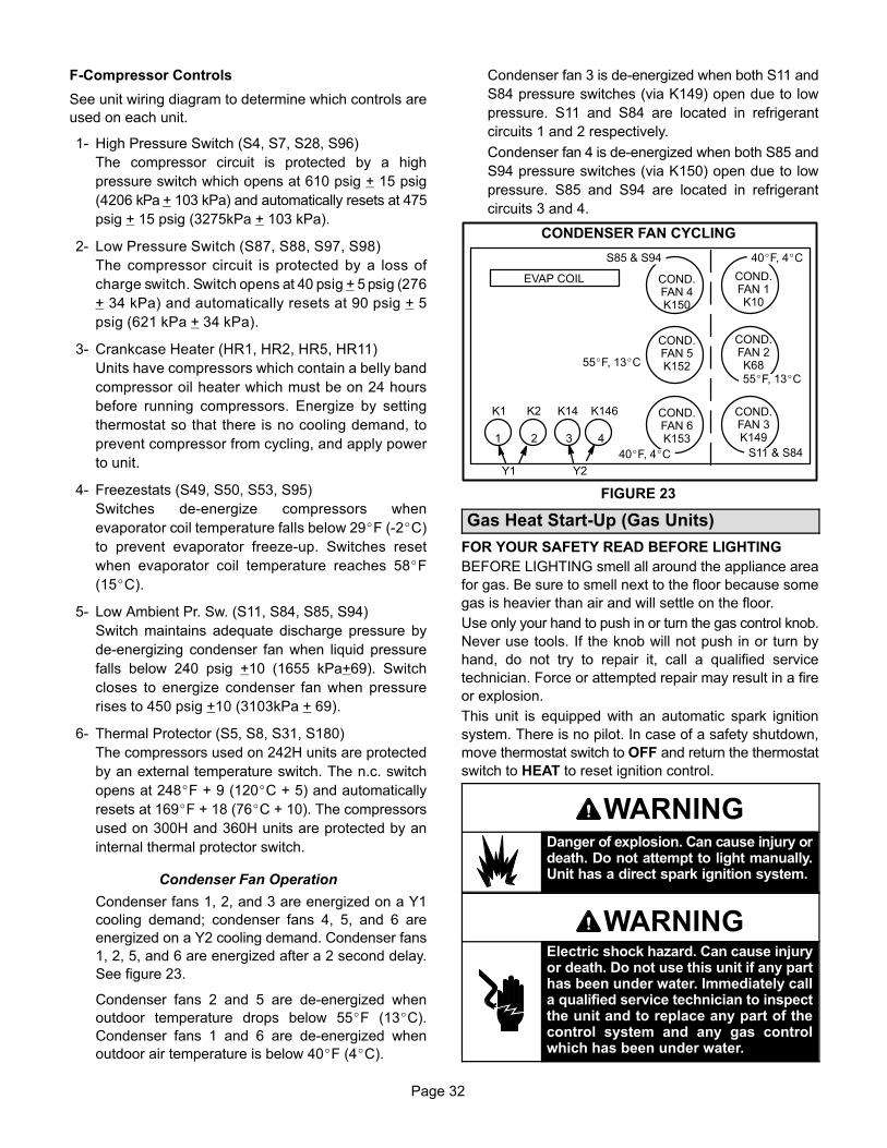
F-Compressor Controls
See unit wiring diagram to determine which controls are
used on each unit.
1- High Pressure Switch (S4, S7, S28, S96)
The compressor circuit is protected by a high
pressure switch which opens at 610 psig + 15 psig
(4206 kPa + 103 kPa) and automatically resets at 475
evaporator coil temperature falls below 29�F (-2�C)
to prevent evaporator freeze-up. Switches reset
when evaporator coil temperature reaches 58�F
(15�C).
5- Low Ambient Pr. Sw. (S11, S84, S85, S94)
Switch maintains adequate discharge pressure by
de-energizing condenser fan when liquid pressure
falls below 240 psig +10 (1655 kPa+69). Switch
closes to energize condenser fan when pressure
rises to 450 psig +10 (3103kPa + 69).
6- Thermal Protector (S5, S8, S31, S180)
The compressors used on 242H units are protected
by an external temperature switch. The n.c. switch
opens at 248�F + 9 (120�C + 5) and automatically
resets at 169�F + 18 (76�C + 10). The compressors
used on 300H and 360H units are protected by an
internal thermal protector switch.
Condenser Fan Operation
Condenser fans 1, 2, and 3 are energized on a Y1
cooling demand; condenser fans 4, 5, and 6 are
energized on a Y2 cooling demand. Condenser fans
1, 2, 5, and 6 are energized after a 2 second delay.
See figure 23.
Condenser fans 2 and 5 are de-energized when
outdoor temperature drops below 55�F (13�C).
Condenser fans 1 and 6 are de-energized when
outdoor air temperature is below 40�F (4�C).
Condenser fan 3 is de-energized when both S11 and
S84 pressure switches (via K149) open due to low
pressure. S11 and S84 are located in refrigerant
circuits 1 and 2 respectively.
Condenser fan 4 is de-energized when both S85 and
S94 pressure switches (via K150) open due to low
pressure. S85 and S94 are located in refrigerant
circuits 3 and 4.
4
CONDENSER FAN CYCLING
FIGURE 23
COND.FAN 4K150
COND.FAN 1K10
COND.FAN 6K153
COND.FAN 3K149
COND.FAN 5K152
COND.FAN 2K68
1 2 3
Y1 Y2
S11 & S84
S85 & S94
55�F, 13�C
55�F, 13�C
40�F, 4�C
40�F, 4�C
EVAP COIL
K1 K2 K14 K146
Gas Heat Start-Up (Gas Units)
FOR YOUR SAFETY READ BEFORE LIGHTING
BEFORE LIGHTING smell all around the appliance area
for gas. Be sure to smell next to the floor because some
gas is heavier than air and will settle on the floor.
Use only your hand to push in or turn the gas control knob.
Never use tools. If the knob will not push in or turn by
hand, do not try to repair it, call a qualified service
technician. Force or attempted repair may result in a fire
or explosion.
This unit is equipped with an automatic spark ignition
system. There is no pilot. In case of a safety shutdown,
move thermostat switch to OFF and return the thermostat
switch to HEAT to reset ignition control.
WARNINGDanger of explosion. Can cause injury ordeath. Do not attempt to light manually.Unit has a direct spark ignition system.
WARNINGElectric shock hazard. Can cause injuryor death. Do not use this unit if any parthas been under water. Immediately calla qualified service technician to inspectthe unit and to replace any part of thecontrol system and any gas controlwhich has been under water.
Page 33
WARNINGDanger of explosion. Can cause injuryor product or property damage. Ifoverheating occurs or if gas supplyfails to shut off, shut off the manual gasvalve to the appliance before shuttingoff electrical supply.
WARNINGSMOKE POTENTIAL
The heat exchanger in this unit could be a source ofsmoke on initial firing. Take precautions with respectto building occupants and property. Vent initial supply air outside when possible.
WARNINGElectric shock hazard. Can causeinjury or death. Before attempting toperform any service or maintenance,turn the electrical power to unit OFF atdisconnect switch(es). Unit may havemultiple power supplies.
A-Placing Unit In Operation
WARNINGDanger of explosion and fire. Can causeinjury or product or property damage.You must follow these instructionsexactly.
Gas Valve Operation for Honeywell VR8305Q (Figure
24) Series Gas Valve
1- Set thermostat to lowest setting.
2- Turn off all electrical power to appliance.
3- This appliance is equipped with an ignition device
which automatically lights the burner. Do not try to
light the burner by hand.
4- Open or remove the heat section access panel.
HONEYWELL VR8305Q SERIES GAS VALVE
Gas valve knob is shown in OFF position.
FIGURE 24
LOW FIREADJUSTMENT
HIGH FIREADJUSTMENT
INLETPRESSURE
TAP
5- Turn the knob on the gas valve clockwise to OFF.
Do not force.
6- Wait five minutes to clear out any gas. If you then
smell gas, STOP! Immediately call your
gas supplier from a neighbor's phone. Follow the gas
supplier's instructions. If you do not smell gas, go to
the next step.
7- Turn the knob on the gas valve counterclockwise
to ON. Do not force.
8- Close or replace the heat section access panel.
9- Turn on all electrical power to unit.
10- Set thermostat to desired setting.
11- The ignition sequence will start.
12- If the appliance does not light the first time (gas line
not fully purged), it will attempt up to two more
ignitions before locking out.
13- If lockout occurs, repeat steps 1 through 10.
14- If the appliance will not operate, follow the
instructions “Turning Off Gas to Appliance” and call
your service technician or gas supplier.
Turning Off Gas to Unit
1- If using an electromechanical thermostat, set to the
lowest setting.
2- Before performing any service, turn off all electrical
power to the unit.
3- Open or remove the heat section access panel.
4- Turn the knob on the gas valve clockwise to
OFF. Do not force.
5- Close or replace the heat section access panel.
Page 34
Heating Operation and Adjustments
(Gas Units)
A-Heating Sequence of Operation
1- On a heating demand the combustion air inducer
starts immediately.
2- Combustion air pressure switch proves inducer
operation. After a 30-second pre-purge, power is
allowed to ignition control. Switch is factory set and
requires no adjustment.
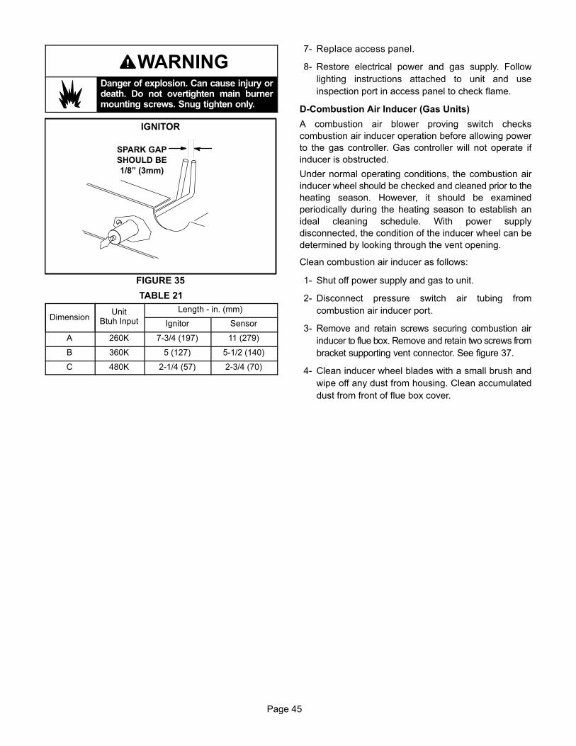
3- Spark ignitor energizes and gas valve solenoid opens.
4- Spark ignites gas, ignition sensor proves the flame
and combustion continues.
5- If flame is not detected after first ignition trial, ignition
control will repeat steps 3 and 4 two more times
before locking out the gas valve.
6- For troubleshooting purposes, an ignition attempt
after lock out may be re-established manually. Move
thermostat to “OFF” and return thermostat switch to
“HEAT” position.
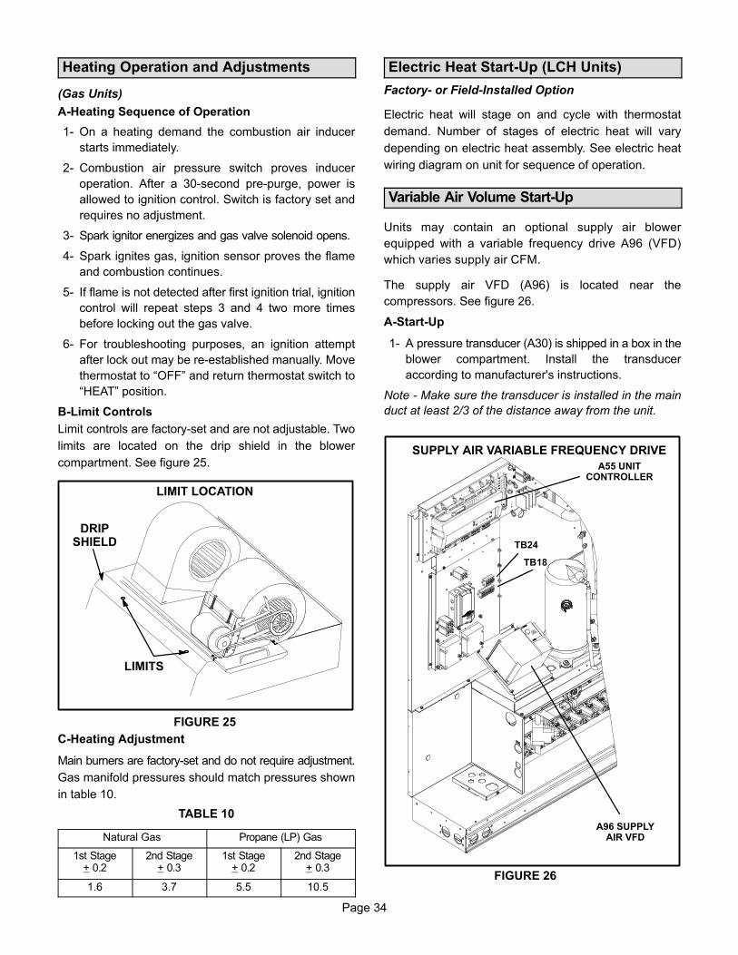
B-Limit Controls
Limit controls are factory-set and are not adjustable. Two
limits are located on the drip shield in the blower
compartment. See figure 25.
LIMIT LOCATION
FIGURE 25
LIMITS
DRIPSHIELD
C-Heating Adjustment
Main burners are factory-set and do not require adjustment.
Gas manifold pressures should match pressures shown
in table 10.
TABLE 10
Natural Gas Propane (LP) Gas
1st Stage+ 0.2
2nd Stage+ 0.3
1st Stage+ 0.2
2nd Stage+ 0.3
1.6 3.7 5.5 10.5
Electric Heat Start-Up (LCH Units)
Factory- or Field-Installed Option
Electric heat will stage on and cycle with thermostat
demand. Number of stages of electric heat will vary
depending on electric heat assembly. See electric heat
wiring diagram on unit for sequence of operation.
Variable Air Volume Start-Up
Units may contain an optional supply air blower
equipped with a variable frequency drive A96 (VFD)
which varies supply air CFM.
The supply air VFD (A96) is located near the
compressors. See figure 26.
A-Start-Up
1- A pressure transducer (A30) is shipped in a box in the
blower compartment. Install the transducer
according to manufacturer's instructions.
Note - Make sure the transducer is installed in the main
duct at least 2/3 of the distance away from the unit.
FIGURE 26
SUPPLY AIR VARIABLE FREQUENCY DRIVE
A96 SUPPLYAIR VFD
A55 UNITCONTROLLER
TB24
TB18
Page 35
PRESSURE TRANSDUCER WIRING
TWISTED
PAIR
UNUSED WIRE
DRAINNOT
CONNECTED
NOT
CONNECTED
TWISTED
PAIR
FIGURE 27
UNITTB18
A30
9
6
26
0
_
+
UNITTB24
2- Two twisted pairs of shielded cable must be used to
connect the pressure transducer. See figure 27.
3- Open all zone dampers and/or boxes.
4- Locate the A55 Unit Controller. Refer to figure 26.
5- Use the Unit Controller to calibrate the blower CFM.
Select the SETUP->TEST & BALANCE->BLOWER
menu to start the blower. The Unit Controller will
display the percent of blower speed. Adjust blower
speed percentage to meet design airflow
specifications. Allow blower speed to stabilize.
6- Press SAVE to display the current static pressure.
If the static pressure meets the design
specification, press SAVE again to set the setpoint.
If the static pressure does not meet the design
specification, adjust the pressure and press SAVE
to set the setpoint.
7- Record new setpoints in table 11.
Note - The Unit Controller will lock-out the unit for 5
minutes if static pressure exceeds 2.0”w.c. for 20
seconds. The Unit Controller will permanently shut down
the unit after three occurrences. See Unit Controller
parameters 110, 42, and 43 to adjust default values.
8- If the desired CFM cannot be met with current pulley
setup, refer to the Blower Operation and Adjustments
section to adjust CFM.
B-Unit Operation
Use the Unit Controller to check unit mechanical
operation. See the Service - Test section of the Unit
Controller manual.
TABLE 11RECORD ADJUSTED SETPOINTS
ParameterSetpoint
DescriptionSetpoint
“w.c.DisplaySetting
386 Smoke
387 Ventilation
388 Heating
389 Cooling
C-Supply Air VFD Bypass (Optional)
IMPORTANT - All dampers must be open to prevent
damage to duct work and dampers.
1- Turn off all power to unit.
2- Locate J/P247 and J/P248 connectors near the VFD.
See figure 28.
3- Disconnect P247 from J247 and connect J249 to
P247. See figure 29.
FIGURE 28
SUPPLY AIR VFD BYPASS COMPONENTS
K203A & B
LOCATED IN
THIS AREA
Page 36
J249
FIGURE 29
SUPPLY AIR VFD BYPASS CONNECTOR
P247
J247
P247
Disconnect Connect
4- Disconnect J248 from P248 and connect connect
P248 jumper plug to J248. P248 jumper plug is
attached to the J248 wire harness near the J248
jack connector. See figure 30.
P248Jumper
Plug
J248
FIGURE 30
SUPPLY AIR VFD BYPASS CONNECTOR
P248
J248
Disconnect
Connect
5- Locate VFD control relay K203 on the lower control
panel next to terminal strip TB24. See figure 28.
6- Locate wires labeled K203-A and K203-B in area
shown in figure 28. Disconnect insulated terminals.
7- Locate wires labeled K3-A and K3-B coming from K3
blower relay. Connect to K203-A to K3-A and K203-B
to K3-B.
8- Restore power to unit. Blower will operate in constant
air volume (CAV) mode.
9- Check the indoor blower motor nameplate for full load
amperage (FLA) value. Measure the amp readings
from the indoor blower motor operating in bypass
mode. If measured amps are higher than nameplate
FLA value, decrease the CFM by opening (turning
counterclockwise) the motor pulley. See figure 15. Do
not exceed minimum and maximum number of pulley
turns as shown in table 3.
Multi-Staged Air Volume Start-Up
LGH/LCH300 & 360 Units Only
Units may contain an optional supply air blower
equipped with a variable frequency drive A96 (VFD)
which stages supply air CFM.
The supply air VFD (A96) is located near the
compressors. See figure 26.
A-Design Specifications
Use table 12 to fill in field-provided, design specified
blower CFM for appropriate unit.
If only high and low cooling design specifications are
provided, set the medium cooling CFM at the high or low
cooling design spec or any CFM between.
B-Set Maximum CFM
Use table 12 to determine highest blower CFM for
appropriate unit. Adjust the blower pulley to deliver that
amount of CFM with only the blower operating. See the
Blower Operation and Adjustment section.
TABLE 12CFM DESIGN SPECIFICATIONS -
300 & 360 UNITS WITH STAGED BLOWER
No. Of Stages / Con
trol TypeBlower Speed1 Design
Specified CFM
2 Stages / T'Stat
Htg.
Clg. High
Clg. Low
Ventilation
3 Stages / T'Stat2
Htg.
Clg. High
Clg. Med.
Clg. Low
Ventilation
4 Stages /
Room Sensor OR
Discharge Air
Control
Htg.
Clg. High
Clg. Med. High
Clg. Med. Low
Clg. Low
Ventilation
1Available blower speeds vary by unit and thermostat stages.2Requires a transfer relay (K27) and three-stage thermostat.
Page 37
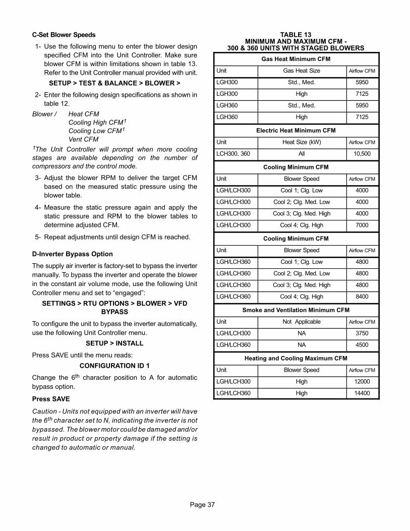
C-Set Blower Speeds
1- Use the following menu to enter the blower design
specified CFM into the Unit Controller. Make sure
blower CFM is within limitations shown in table 13.
Refer to the Unit Controller manual provided with unit.
SETUP > TEST & BALANCE > BLOWER >
2- Enter the following design specifications as shown in
table 12.
Blower / Heat CFM
Cooling High CFM1
Cooling Low CFM1
Vent CFM
1The Unit Controller will prompt when more cooling
stages are available depending on the number of
compressors and the control mode.
3- Adjust the blower RPM to deliver the target CFM
based on the measured static pressure using the
blower table.
4- Measure the static pressure again and apply the
static pressure and RPM to the blower tables to
determine adjusted CFM.
5- Repeat adjustments until design CFM is reached.
D-Inverter Bypass Option
The supply air inverter is factory-set to bypass the inverter
manually. To bypass the inverter and operate the blower
in the constant air volume mode, use the following Unit
Controller menu and set to “engaged”:
SETTINGS > RTU OPTIONS > BLOWER > VFD
BYPASS
To configure the unit to bypass the inverter automatically,
use the following Unit Controller menu.
SETUP > INSTALL
Press SAVE until the menu reads:
CONFIGURATION ID 1
Change the 6th character position to A for automatic
bypass option.
Press SAVE
Caution - Units not equipped with an inverter will have
the 6th character set to N, indicating the inverter is not
bypassed. The blower motor could be damaged and/or
result in product or property damage if the setting is
changed to automatic or manual.
TABLE 13MINIMUM AND MAXIMUM CFM -
300 & 360 UNITS WITH STAGED BLOWERS
Gas Heat Minimum CFM
Unit Gas Heat Size Airflow CFM
LGH300 Std., Med. 5950
LGH300 High 7125
LGH360 Std., Med. 5950
LGH360 High 7125
Electric Heat Minimum CFM
Unit Heat Size (kW) Airflow CFM
LCH300, 360 All 10,500
Cooling Minimum CFM
Unit Blower Speed Airflow CFM
LGH/LCH300 Cool 1; Clg. Low 4000
LGH/LCH300 Cool 2; Clg. Med. Low 4000
LGH/LCH300 Cool 3; Clg. Med. High 4000
LGH/LCH300 Cool 4; Clg. High 7000
Cooling Minimum CFM
Unit Blower Speed Airflow CFM
LGH/LCH360 Cool 1; Clg. Low 4800
LGH/LCH360 Cool 2; Clg. Med. Low 4800
LGH/LCH360 Cool 3; Clg. Med. High 4800
LGH/LCH360 Cool 4; Clg. High 8400
Smoke and Ventilation Minimum CFM
Unit Not Applicable Airflow CFM
LGH/LCH300 NA 3750
LGH/LCH360 NA 4500
Heating and Cooling Maximum CFM
Unit Blower Speed Airflow CFM
LGH/LCH300 High 12000
LGH/LCH360 High 14400
Page 38
Optional Economizer Settings
A-Control Settings
The economizer, when configured, controls:
� Damper position, which determines how much
outdoor air is used to meet free cooling or indoor air
quality requirements, and
� Can be used to control optional power exhaust fans.
On a cooling demand, outdoor air is used for free cooling
instead of first-stage compressor(s) when outdoor air is
suitable.
To enable the economizer, if installed, go to SETUP >
INSTALL and go through the wizard. When reaching
Configuration ID 1, position 2 will need to be set to the
applicable type of economizer. Valid types are as
indicated below:
� M = Motorized Outdoor Air Damper Only
� T = Economizer - Temperature (Note: Used for both
set point and offset temperature control.)
� G = Economizer - Global
� S = Economizer - Single Enthalpy
� D = Economizer - Dual Enthalpy
The following options are available depending on
economizer set above. These settings are available
through the main menu at SETUP > TEST & BALANCE >
DAMPER.
B-Damper Minimum Position Setting
Use the following menu path to modified the minimum
damper positions for both high and low operations.
SETUP > TEST & BALANCE > DAMPER > MINDAMPER POSITION BLOWER ON HIGH = .%
SETUP > TEST & BALANCE > DAMPER > MINDAMPER POSITION BLOWER ON LOW = .%
C-Economizer Operation
Note - Use indicating lights on Unit Controller to determine
thermostat demand.
See table 18 for economizer operation with a standard
two-stage thermostat
Table 19 shows economizer operation with an energy
management system which uses a global sensor.
Both tables show the occupied and unoccupied time
period. The occupied time period is determined by the
thermostat or energy management system.
Table 20 shows economizer operation in zone sensor
mode.
D-IAQ Damper Operation
The Unit Controller has a 0-10VDC IAQ input for a
standard 0-2000ppm CO2 sensor. The economizer
starts opening at a CO2 level of 500 ppm (default) and
reaches full open at a CO2 level of 1000ppm.
Adjustments may be made to the indoor air quality
parameters to alter operation or meet required
specifications. Use the user interface to change
Parameter 117 through 119. Go to SETTINGS > RTU
OPTIONS > EDIT PARAMETER.
If the economizer is operating in the free cooling mode
and the IAQ sensor demands more fresh air, the IAQ
demand will override the free cooling demand to open the
dampers further or to keep them open.
The IAQ function is not energized during the unoccupied
or night time period.
TABLE 14
MENU INTERFACE (LEVEL 1 - SETTINGS) - M (MOTORIZED OUTDOOR AIR DAMPER ONLY)
Level 2 Level 3 Level 4 Level 5USE THE ADJUST AND SET VALUES ARROWS TO SCROLL UP OR DOWN FOR SELECTION OPTIONS.
RTU OPTION DAMPER
MIN DAMPER POSITION
BLOWER ON HIGH = X.X %
MIN DAMPER POSITION
BLOWER ON LOW = X.X %
DEMAND CONTROL VENT
DAMPER START OPEN = XXXX.X PPM
DEMAND CONTROL VENT
DAMPER FULL OPEN = XXXX.X PPM
DEMAND CONTROL VENT
DAMPER MAX OPENING = XXX.X%
FRESH AIR HEATING ENABLE FAH = YES OR NO
FRESH AIR HEATING FAH SETPOINT = XX F
FRESH AIR COOLING ENABLE AFC = YES OR NO
FRESH AIR COOLING AFC SETPOINT = XX F
Page 39
TABLE 15
MENU INTERFACE (LEVEL 1 - SETTINGS) - T (TEMPERATURE ECONOMIZER)
Level 2 Level 3 Level 4 Level 5USE THE ADJUST AND SET VALUES ARROWS TO SCROLL UP OR DOWN FOR SELECTION OPTIONS.
RTU OPTION DAMPER
ECONOMIZER TEMP ECON TYPE = TEMPERATURE OFFSET OR TEMPERATURE SETPT
ECONOMIZER
OAT SETPOINT = XX.X F
FREE COOLING
SUPPLY AIR SETPOINT = XX F
MIN DAMPER POSITION
BLOWER ON HIGH = X.X %
MIN DAMPER POSITION
BLOWER ON LOW = X.X %
DEMAND CONTROL VENT
DAMPER START OPEN = XXXX.X PPM
DEMAND CONTROL VENT
DAMPER FULL OPEN = XXXX.X PPM
DEMAND CONTROL VENT
DAMPER MAX OPENING = XXX.X%
FRESH AIR HEATING ENABLE FAH = YES OR NO
FRESH AIR HEATING FAH SETPOINT = XX F
FRESH AIR COOLING ENABLE AFC = YES OR NO
FRESH AIR COOLING AFC SETPOINT = XX F
TABLE 16
MENU INTERFACE (LEVEL 1 - SETTINGS) - G (GLOBAL ECONOMIZER)
Level 2 Level 3 Level 4 Level 5USE THE ADJUST AND SET VALUES ARROWS TO SCROLL UP OR DOWN FOR SELECTION OPTIONS.
RTU OPTION DAMPER
FREE COOLING
SUPPLY AIR SETPOINT = XX F
MIN DAMPER POSITION
BLOWER ON HIGH = X.X %
MIN DAMPER POSITION
BLOWER ON LOW = X.X %
DEMAND CONTROL VENT
DAMPER START OPEN = XXXX.X PPM
DEMAND CONTROL VENT
DAMPER FULL OPEN = XXXX.X PPM
DEMAND CONTROL VENT
DAMPER MAX OPENING = XXX.X%
FRESH AIR HEATING ENABLE FAH = YES OR NO
FRESH AIR HEATING FAH SETPOINT = XX F
FRESH AIR COOLING ENABLE AFC = YES OR NO
FRESH AIR COOLING AFC SETPOINT = XX F
Page 40
TABLE 17
DEMAND CONTROL VENTILATION PARAMETERS
Control Parameter Control Value
Units DescriptionNo Screen Name
Parameter ShortDescription Min. Default Max.
117 DCV MAX DAMPER OPENDemand Control
Ventilation MaximumDamper Open
0 100 100 %Maximum allowed demand controlventilation damper open position.
118 DCV DAMP START OPENDemand Control
Ventilation DamperStart Open
0 700 2000 PPM
� Damper “start open" CO2 set point
for Demand Control Ventilation.
� Level where fresh air damper be
gins to open.
119 DCV DAMP FULL OPEN
Demand ControlVentilation MaximumDamper Full Open
Set Point
0 1200 2000 PPM
� Damper “full open" CO2 set point
for Demand Control Ventilation.
� Level where fresh air damper is
opened to maximum.
120 DCV HI TMP OV FL CL
Demand ControlVentilation Outdoor
Air Control HiTemperature
Override Full Closed
-31.0 105.0 132.0 °FHigh outdoor air temp. where fresh airdamper is closed to minimum position.
121 DCV HI TMP OV ST CL
Demand ControlVentilation Outdoor
Air Control HiTemperature
Override StartClosing
-31.0 75.0 132.0 °FHigh outdoor air temperature wherefresh air damper begins to close.
122 DCV LO TMP OV FL CL
Demand ControlVentilation Outdoor
Air Control LowTemperature
Override Full Closed
-31.0 10.0 132.0 °FLow outdoor air temperature wherefresh air damper is closed to minimumposition
123 DCV LO TMP OV ST CL
Demand ControlVentilation Outdoor
Air Control LowTemperature
Override StartClosing
-31.0 40.0 132.0 °FLow outdoor air temp. where fresh airdamper begins to close.
134 IAQ INPUT MODEIndoor Air Quality In
put Mode0 1 6 Option
IAQ input source and mode (0-3 operate only when blower is on).
0- Demand Control Ventilation SystemIndoor Air Quality. Either P298-3 ornetwork indoor air quality.
1- Demand Control Ventilation SystemIndoor Air Quality. Either P298-3 ornetwork Indoor Air Quality with nooutdoor air temperature limits.
2- Outdoor Air Control Sensor A24(A133_P194-6) (TB22-6).
3- Outdoor Air Control Sensor A24(A133_P194-6) (TB22-6) with no outdoor air temperature limits.
4- Demand Control Ventilation SystemIndoor Air Quality. Either P298-3 ornetwork Indoor Air Quality withblower on/auto operation.
5- Demand Control Ventilation SystemIndoor Air Quality. Either P298-3 ornetwork Indoor Air Quality withblower on/auto operation with no outdoor air temperature limits.
Page 41
Page 42
TABLE 18
ECONOMIZER OPERATION - Standard Two-Stage Thermostat (Default Option)ÁÁÁÁÁÁÁÁÁÁÁÁÁÁÁÁÁÁÁÁ
*Damper will modulate to maintain 55�F supply air when parameter 164 is changed to setting “0”. Note - Modulating dampers adjust to control supply
air (RT6) to 55�F (13�C).
Page 43
Optional Outdoor Air CFM Control
Outdoor Air CFM Control is a factory-installed option
available on units equipped with a supply air variable
frequency drive (VFD) and economizer.
The Unit Controller modulates outdoor air dampers to
maintain a constant amount of outdoor air regardless of
blower speed. This ensures minimum ventilation
requirements are met at lower supply air speeds.
The Unit Controller uses a velocity sensor (A24) to
modulate dampers. The sensor is located in the outdoor
air stream. See figure 31.
Set Damper Minimum Position
1- Enable the Outdoor Air Control feature and set the
velocity sensor range using the M3 Unit Controller
SETUP > INSTALL menu. Navigate to
Configuration ID 1. Set position 8 to:
H Outdoor air control installed with A24 control set
for low range (0-1968ft/min)
Note - The configuration ID setting (H) must be paired with
the “low” jumper position on the A24 control (see figure
32). The jumper is factory-set at low range (0-1968ft/min).
2- Operate the blower in high speed and adjust the
minimum damper position. Use SETUP > TEST &
BALANCE > DAMPER > MIN DAMPER POSITION
menu. Adjust minimum damper position and press
SAVE. The Unit Controller will automatically save and
display the velocity setpoint. Press SAVE again to
confirm.
Note - The minimum damper position setting MUST be
set lower than the OAC max damper position setting (50%
default). To modify the max damper position setting,
navigate to SETTINGS > EDIT PARAMETERS and select
parameter 117 (DCV MAX DAMPER OPEN).
Additional outdoor air CFM control settings are available.
See parameters 117 and 134 in the Unit Controller manual.
Make adjustments through the SETTINGS > EDIT
PARAMETERS menu; select the required parameter.
3- Replace A24 control cover.
Note - Refer to local codes or authorities having
jurisdiction when determining design minimum outdoor
air requirements.
FIGURE 31
VELOCITY SENSOR LOCATION
A24
SENSOR
A24
CONTROL
Velocity Sensor Settings
The A24 control is factory-set for 0-10m/s (0-1968ft/min).
FIGURE 32
VELOCITY SENSOR (A24) JUMPER SETTINGS
V+GND
AV
0-10m/s (0-1968ft/min.)
24VAC
Common
Airflow Output
(0-10VDC)
123
JUMPERS
t90HIMEDLOIU
t90HI
MEDLOI
U
Sets respond time to 4 sec.
Sets output signal to voltage
Page 44
Service
The unit should be inspected once a year by a qualified
service technician.
CAUTIONLabel all wires prior to disconnection when servicingcontrols. Wiring errors can cause improper and dangerous operation. Verify proper operation after servicing.
A-Filters
Units are equipped with twelve 20 X 20 X 2” (508 X 508
X 51mm) filters. Filters should be checked monthly and
replaced when necessary with filters of like kind and
size. Take note of air flow direction marking on filter
frame when reinstalling filters. See figure 33.
Note - Filters must be U.L.C. certified or equivalent for use
in Canada.
B-Lubrication
All motors are lubricated at the factory. No further
lubrication is required.
FIGURE 33
REMOVE FILTERS
PULL TOREMOVEFILTERS
Blower shaft bearings are prelubricated. For extended
bearing life, relubricate at least once every two years with
a lithium base grease, such as Alvania 3 (Shell Oil),
Chevron BRB2 (Standard Oil) or Regal AFB2 (Texas Oil).
Use a hand grease gun for relubrication. Add only enough
grease to purge through the bearings so that a bead of
grease appears at the seal lip contacts.
C-Burners (Gas Units)
Periodically examine burner flames for proper
appearance during the heating season. Before each
heating season examine the burners for any deposits or
blockage which may have occurred.
Clean burners as follows:
1- Turn off both electrical power and gas supply to unit.
2- Open burner compartment access panel.
3- Remove screws securing burner assembly to burner
support and remove assembly. See figure 34. Clean
as necessary.
BURNER BOX ASSEMBLY480KBTUH SHOWN
FIGURE 34
GASMANIFOLD
GASVALVE BURNER ASSEMBLY
SECURED WITH
MULTIPLE SCREWS
4- Locate the ignitor under the left burners. Check
ignitor spark gap with appropriately sized twist drills
or feeler gauges. See figure 35.
5- Check the alignment of the ignitor and the sensor as
shown in figure 36 and table 21.
6- Replace burners and screws securing burner.
Page 45
WARNINGDanger of explosion. Can cause injury ordeath. Do not overtighten main burnermounting screws. Snug tighten only.
FIGURE 35
IGNITOR
SPARK GAP
SHOULD BE
1/8” (3mm)
TABLE 21
DimensionUnit
Btuh Input
Length - in. (mm)
Ignitor Sensor
A 260K 7-3/4 (197) 11 (279)
B 360K 5 (127) 5-1/2 (140)
C 480K 2-1/4 (57) 2-3/4 (70)
7- Replace access panel.
8- Restore electrical power and gas supply. Follow
lighting instructions attached to unit and use
inspection port in access panel to check flame.
D-Combustion Air Inducer (Gas Units)
A combustion air blower proving switch checks
combustion air inducer operation before allowing power
to the gas controller. Gas controller will not operate if
inducer is obstructed.
Under normal operating conditions, the combustion air
inducer wheel should be checked and cleaned prior to the
heating season. However, it should be examined
periodically during the heating season to establish an
ideal cleaning schedule. With power supply
disconnected, the condition of the inducer wheel can be
determined by looking through the vent opening.
Clean combustion air inducer as follows:
1- Shut off power supply and gas to unit.
2- Disconnect pressure switch air tubing from
combustion air inducer port.
3- Remove and retain screws securing combustion air
inducer to flue box. Remove and retain two screws from
bracket supporting vent connector. See figure 37.
4- Clean inducer wheel blades with a small brush and
wipe off any dust from housing. Clean accumulated
dust from front of flue box cover.
Page 46
A
B
C
FIGURE 36
IGNITOR AND SENSOR POSITION
TOP VIEW
SIDE VIEW IGNITOR SIDE VIEW SENSOR
1-3/4”(45mm)
3/8”(10mm)
1-3/8”(35mm)
BURNER BOX
Gas Flow Gas Flow
13/16”(21mm)
A
B
C
IGNITOR SENSOR
5- Return combustion air inducer motor and vent
connector to original location and secure with
retained screws. It is recommended that the
combustion air inducer gasket be replaced during
reassembly.
6- Clean combustion air inlet louvers on heat access
panel using a small brush.
E-Flue Passageway and Flue Box (Gas Units)
1- Remove combustion air inducer assembly as
described in section D.
2- Remove flue box cover. Clean with a wire brush as
required.
3- Clean tubes with a wire brush.
4- Reassemble the unit. The flue box cover gasket and
combustion air inducer gasket should also be
replaced during reassembly.
HEAT EXCHANGER ASSEMBLY
FIGURE 37
BURNER
COMBUSTIONAIR INDUCER
VENTCONNECTOR
GAS VALVE
HEATEXCHANGER
TUBE
Page 47
F-Evaporator Coil
Inspect and clean coil at beginning of each cooling season.
Clean using mild detergent or commercial coil cleaner.
Flush coil and condensate drain with water taking care not
to get insulation, filters and return air ducts wet.
G-Supply Air Blower Wheel
Annually inspect supply air blower wheel for accumulated dirt
or dust. Turn off power before attempting to remove access
panel or to clean blower wheel.
H-Condenser Coil
Clean condenser coil annually with water and inspect
monthly during the cooling season. Access panels are
provided on front and back of condenser section.
Clean the all-aluminum coil by spraying the coil steadily
and uniformly from top to bottom. Do not exceed 900 psi or a
45� angle; nozzle must be at least 12 inches from the coil
face. Take care not to fracture the braze between the fins