Installation & Service Instructions Performa 24i HE This is a Wall Mounted Powered Flue Condensing Combination Boiler Gas Fired Central Heating Unit. The boiler meets the requirements of Statutory Instrument “ The Boiler (Efficiency) Regulations 1993 N o 3083” and is deemed to meet the requirements of Directive 92/42/EEC on the energy efficiency requirements for new hot water boilers fired with liquid or gaseous fuels:- Type test for purpose of Regulation 5 certified by: Notified Body 0051. Product/Production certified by: Notified Body 0051. For use in GB/IE only.
Transcript
Installation & Service Instructions Performa24i HE
This is a Wall Mounted Powered Flue Condensing Combination Boiler Gas Fired Central Heating Unit.
The boiler meets the requirements of Statutory Instrument “ The Boiler (Efficiency) Regulations 1993 No 3083” and isdeemed to meet the requirements of Directive 92/42/EEC on the energy efficiency requirements for new hot waterboilers fired with liquid or gaseous fuels:-
Type test for purpose of Regulation 5 certified by: Notified Body 0051.
Product/Production certified by:Notified Body 0051.
For use in GB/IE only.
2 Publication No. 5111813
Natural Gas
Potterton Performa 24i HEG.C.No 47 393 12
This product has an energy rating (B) on a scale of A to G.For more information see www.boilers.org.uk. This is a certification mark.
3
CONTENTS
Publication No. 5111813
Legislation 4
1.0 Introduction 5
2.0 General Layout 6
3.0 Appliance Operation 7
4.0 Technical Data 9
5.0 Dimensions and Fixings 10
6.0 System Details 11
7.0 Site Requirements 14
8.0 Installation 20
9.0 Commissioning 25
10.0 Completion 27
11.0 Servicing 28
12.0 Changing Components 30
13.0 Electrical 40
14.0 Short Parts List 41
15.0 Fault Finding 42
Section Page
LEGISLATION
4 Publication No. 5111813
Codes of Practice, most recent version shouldbe used
IMPORTANT - Installation, Commissioning, Service & Repair
This appliance must be installed in accordance with the manufacturer’sinstructions and the regulations in force. Read the instructions fully beforeinstalling or using the appliance.
In GB, this must be carried out by a competent person as stated in the GasSafety (Installation & Use) Regulations.
Definition of competence: A person who works for a CORGI registeredcompany and holding current certificates in the relevant ACS modules, orvalid ACoP equivalents, is deemed competent.
In IE, this must be carried out by a competent person as stated in I.S. 813“Domestic Gas Installations”.
Lifting - This product should be lifted and handled by two people. Stoopingshould be avoided and protective equipment worn where necessary. Carrying& lifting equipment should be used as required, e.g. when installing in a loftspace.
The addition of anything that may interfere with the normal operation of theappliance without express written permission from the manufacturer or hisagent could invalidate the appliance warranty. In GB this could also infringethe Gas Safety (Installation and Use) Regulations.
Warning - Check the information on the data plate is compatible with localsupply conditions.
“Benchmark” Log Book
As part of the industry-wide “Benchmark” initiative all Potterton boilers nowinclude an Installation, Commissioning and Service Record Log Book. Pleaseread the Log Book carefully and complete all sections relevant to theappliance and installation. These include sections on the type of controlsemployed, flushing the system, burner operating pressure etc. The details ofthe Log Book will be required in the event of any warranty work. Also, there isa section to be completed at each subsequent regular service visit. The LogBook must be left with the user.
All CORGI registered installers carry a CORGI identification card and have aregistration number. Both should be recorded in your boiler Log Book. Youcan check your installer is registered by telephoning +44 (0)1256 372300 orwriting to:-
1 Elmwood,Chineham Business Park,
Crockford Lane,Basingstoke. RG24 8WG
Potterton declare that no substances harmful tohealth are contained in the appliance or usedduring appliance manufacture.
The appliance is suitable only for installation in GBand IE and should be installed in accordance withthe rules in force, and only used in a suitablyventilated location.
In GB, the installation must be carried out by a CORGIRegistered Installer. It must be carried out in accordancewith the relevant requirements of the:• Gas Safety (Installation & Use) Regulations.• The appropriate Building Regulations either The
Building Regulations, The Building Regulations (Scotland), Building Regulations (Northern Ireland).
• The Water Fittings Regulations or Water Byelaws in Scotland.
• The Current I.E.E. Wiring Regulations.
Where no specific instructions are given, referenceshould be made to the relevant British Standard Code ofPractice.
In IE, the installation must be carried out by a competentPerson and installed in accordance with the currentedition of I.S. 813 ‘Domestic Gas Installations’, thecurrent Building Regulations and reference should bemade to the current ETCI rules for electrical installation.
All systems must be thoroughly flushed andtreated with inhibitor (see section 6.2).
In GB the following Codes of Practice apply:Standard ScopeBS 6891 Gas Installation.BS 5546 Installation of hot water supplies for
domestic purposes.BS 5449 Forced circulation hot water systems.BS 6798 Installation of gas fired hot water boilers.BS 5440 Part 1 Flues.BS 5440 Part 2 Ventilation.BS 7074 Expansion vessels and ancillary equipment
for sealed water systems.BS 7593 Treatment of water in domestic hot water
central heating systems.
In IE the following Codes of Practice apply:Standard ScopeI.S. 813 Domestic Gas Installations.The following BS standards give valuable additional information;BS 5546 Installation of hot water supplies for
domestic purposes.BS 5449 Forced circulation hot water systems.BS 7074 Expansion vessels and ancillary equipment
for sealed water systems.BS 7593 Treatment of water in domestic hot water
central heating systems.
5
1.0 INTRODUCTION
Publication No. 5111813
1.1 Description
1. The Potterton Performa 24i HE is a fully automaticgas fired wall mounted condensing combination boiler.It is room sealed and fan assisted, and will servecentral heating and mains fed domestic hot water.
2.The unit incorporates a small storage cylinder builtinto the boiler providing hot water the moment the tapis turned on.
3. The boiler is set to give a maximum output of 29.4 kW in both modes.
4. It is designed for use on Natural Gas (G20) and canbe converted to use Propane.
5. The boiler is suitable for use only on fully pumpedsealed heating systems. Priority is given to domestichot water.
6. The boiler data badge gives details of the model,serial number and Gas Council number and is situatedon the control box. It is visible when the case frontpanel is removed (Fig. 1).
7. The boiler is intended to be installed in residential /commercial / light industrial E.M.C. environments on agoverned meter supply only.
8. The boiler must be installed with one of the purposedesigned flues such as the standard horizontal flue kit,part no. 5111073.
9. All systems must be thoroughly flushed andtreated with inhibitor (see section 6.2).
1.2 Instant Domestic Hot Water(Expansion Vessel & Pre-Heat Store)
1. The boiler expansion vessel incorporates a smallvolume of stored primary hot water.
2. When the boiler has been off and there is then ademand for domestic hot water the stored primary hotwater ensures that domestic hot water is suppliedinstantly at temperature.
3. The stored hot water is part of the primary circuit.This is not supplied as domestic hot water, which isfresh mains water heated by a heat exchanger withinthe boiler.
4. The stored primary hot water temperature ismaintained whilst the boiler is in operation. During aperiod when there is no demand for heating or hotwater the temperature of the stored primary hot waterwill eventually fall. The boiler will operate occasionallyin order to maintain the temperature. This is indicatedby the domestic hot water mode neon flashing.
1.3 Optional Extras
1. Various flue extensions, bends, vertical flue kits,control accessories etc. are available as optionalextras. These are detailed in a separate publication.
Data Badge
Fig. 1
Control Box
Case Front Panel
2.0 GENERAL LAYOUT
6 Publication No. 5111813
2.1 Layout
1. Air Pressure Switch
2. Expansion Vessel & Pre-Heat Store
3. Burner Manifold
4. Automatic Air Vent
5. DHW Plate Heat Exchanger
6. Circulation Pump
7. Drain Off Point
8. Pressure Relief Valve
9. Position for Optional Integral Timer
10. Central Heating System Pressure Gauge
11. PCB
12. Control Box
13. 3-Way Valve Assembly
14. Condensate Trap
15. Flame Sensing Electrode
16. Spark Electrode
17. Burner
18. Primary Heat Exchanger
19. Fan Assembly
20. Secondary Heat Exchanger
21. On/Off/Reset Selector Switch
22. Central Heating Temperature Control
23. Domestic Hot Water Pre-Heat Control
24. Flame Failure or Blocked Condensate Drain
25. Safety Thermostat Activated (Boiler or Flue)
26. Fault on Fan or Flue
27. Fault on Pump or Low System Pressure
28. Fault on Hot Water Sensor
29. Fault on Central Heating Sensor
30. Power On
31. Domestic Hot Water Mode
32. Central Heating Mode
33. Burner On
When neons 24 to 29 are constantly illuminated, theyindicate the temperature of the central heating water.
19
18
17
14
15
16
13
12 1110
9
21 22 23 10 9
7
6
3
4
5
8
2
1
2
1
0 4
3
bar
30° 40° 50° 60° 70° 80°
Reset
Off
On Preheat
30° 40° 50° 60° 70° 80°
24 25 26 27 28 29
30 31 32 33
20
7
3.0 APPLIANCE OPERATION
Publication No. 5111813
NOTE: All delay timers mentioned in 3.1 and 3.2 are
overridden by domestic hot water demand.
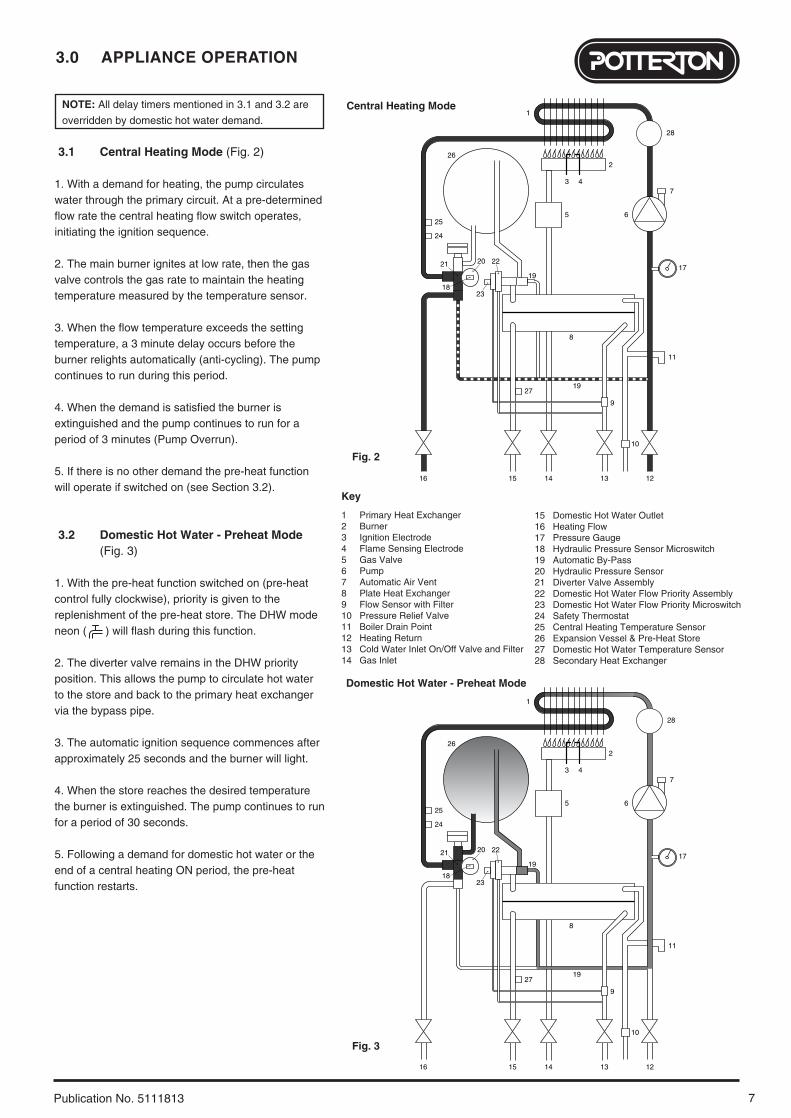
3.1 Central Heating Mode (Fig. 2)
1. With a demand for heating, the pump circulateswater through the primary circuit. At a pre-determinedflow rate the central heating flow switch operates,initiating the ignition sequence.
2. The main burner ignites at low rate, then the gasvalve controls the gas rate to maintain the heatingtemperature measured by the temperature sensor.
3. When the flow temperature exceeds the settingtemperature, a 3 minute delay occurs before theburner relights automatically (anti-cycling). The pumpcontinues to run during this period.
4. When the demand is satisfied the burner isextinguished and the pump continues to run for aperiod of 3 minutes (Pump Overrun).
5. If there is no other demand the pre-heat functionwill operate if switched on (see Section 3.2).
3.2 Domestic Hot Water - Preheat Mode (Fig. 3)
1. With the pre-heat function switched on (pre-heatcontrol fully clockwise), priority is given to thereplenishment of the pre-heat store. The DHW modeneon ( ) will flash during this function.
2. The diverter valve remains in the DHW priorityposition. This allows the pump to circulate hot waterto the store and back to the primary heat exchangervia the bypass pipe.
3. The automatic ignition sequence commences afterapproximately 25 seconds and the burner will light.
4. When the store reaches the desired temperaturethe burner is extinguished. The pump continues to runfor a period of 30 seconds.
5. Following a demand for domestic hot water or theend of a central heating ON period, the pre-heatfunction restarts.
2719
16 15 14 13 12
10
9
11
8
1721
23
20 22
19
28
26
5 6
7
2
3 4
1
25
24
18
1 Primary Heat Exchanger2 Burner 3 Ignition Electrode4 Flame Sensing Electrode5 Gas Valve6 Pump7 Automatic Air Vent8 Plate Heat Exchanger9 Flow Sensor with Filter10 Pressure Relief Valve11 Boiler Drain Point12 Heating Return13 Cold Water Inlet On/Off Valve and Filter14 Gas Inlet
15 Domestic Hot Water Outlet16 Heating Flow17 Pressure Gauge18 Hydraulic Pressure Sensor Microswitch19 Automatic By-Pass20 Hydraulic Pressure Sensor21 Diverter Valve Assembly22 Domestic Hot Water Flow Priority Assembly23 Domestic Hot Water Flow Priority Microswitch24 Safety Thermostat25 Central Heating Temperature Sensor26 Expansion Vessel & Pre-Heat Store27 Domestic Hot Water Temperature Sensor28 Secondary Heat Exchanger
Key
Central Heating Mode
Fig. 2
2719
16 15 14 13 12
10
9
11
8
1721
23
20 22
19
26
5 6
7
2
3 4
1
25
24
18
28
Domestic Hot Water - Preheat Mode
Fig. 3
3.0 APPLIANCE OPERATION
8 Publication No. 5111813
3.3 Domestic Hot Water Mode (Fig. 4)
1. Priority is given to the domestic hot water supply. Ademand at a tap or shower will override any centralheating requirement.
2. The flow of water will operate the DHW flow switchwhich requests the 3 way valve to change position.This will allow the pump to circulate the primary waterthrough the DHW plate heat exchanger and take thestored water to give instant hot water.
3. The burner will light automatically and thetemperature of the domestic hot water is controlled bythe temperature sensor.
4. When the domestic hot water demand ceases theburner will extinguish and the diverter valve willremain in the domestic hot water mode, unless thereis a demand for central heating.
5. If there is no other demand the pre-heat functionwill operate if switched on (see Section 3.2)
IMPORTANT: When the selector switch is in the‘0’ (Off) position the electrical supply to the boiler isisolated. The boiler will not operate and theintegral timer (if fitted) will require resetting oncethe selector switch is set to either Position (i) orPosition (ii).
3.4 Frost Protection Mode
1. The frost protection mode is integral to theappliance and functions only with the selector switch(Section 2.1) in the domestic hot water and centralheating position. If the system temperature falls below5° C then the boiler will fire on its minimum settinguntil a flow temperature of 30° C is reached. Furtherprotection can be incorporated by using a systemfrost thermostat.
3.5 Pump Protection
1. With the selector switch (see Section 2.1) in eitherthe central heating or central heating and domestichot water position the pump will automatically operatefor 1 minute in every 24 hours to prevent sticking.
2719
16 15 14 13 12
10
9
11
8
1721
23
20 22
19
26
5 6
2
3 4
1
25
24
18
7
28
1 Primary Heat Exchanger2 Burner 3 Ignition Electrode4 Flame Sensing Electrode5 Gas Valve6 Pump7 Automatic Air Vent8 Plate Heat Exchanger9 Flow Sensor with Filter10 Pressure Relief Valve11 Boiler Drain Point12 Heating Return13 Cold Water Inlet On/Off Valve and Filter14 Gas Inlet
15 Domestic Hot Water Outlet16 Heating Flow17 Pressure Gauge18 Hydraulic Pressure Sensor Microswitch19 Automatic By-Pass20 Hydraulic Pressure Sensor21 Diverter Valve Assembly22 Domestic Hot Water Flow Priority Assembly23 Domestic Hot Water Flow Priority Microswitch24 Safety Thermostat25 Central Heating Temperature Sensor26 Expansion Vessel & Pre-Heat Store27 Domestic Hot Water Temperature Sensor28 Secondary Heat Exchanger
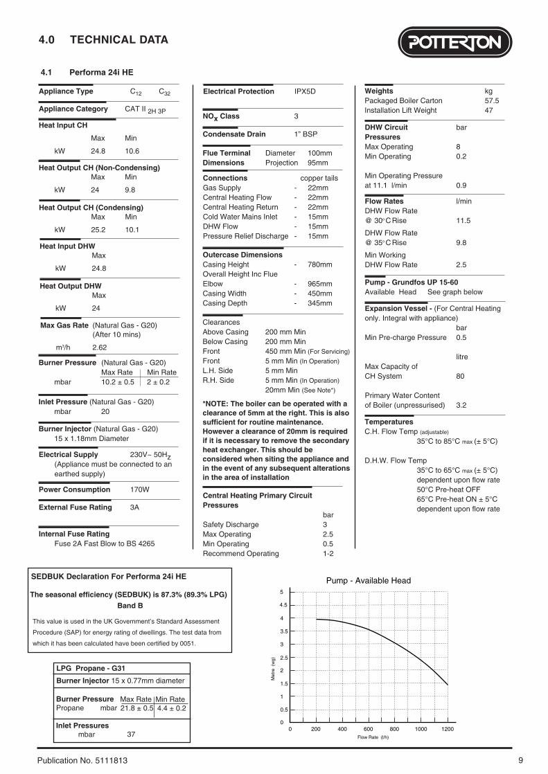
D.H.W. Flow Temp 35°C to 65°C max (± 5°C)dependent upon flow rate50°C Pre-heat OFF65°C Pre-heat ON ± 5°Cdependent upon flow rate
NOx Class 3
Electrical Protection IPX5D
0200 400 600 800 1000 1200
0.5
1
1.5
2
2.5
3
3.5
4
Met
re (
wg)
Flow Rate (l/h)
Pump - Available Head
0
5
4.5
ClearancesAbove Casing 200 mm MinBelow Casing 200 mm MinFront 450 mm Min (For Servicing)
Front 5 mm Min (In Operation)
L.H. Side 5 mm MinR.H. Side 5 mm Min (In Operation)
20mm Min (See Note*)
*NOTE: The boiler can be operated with aclearance of 5mm at the right. This is alsosufficient for routine maintenance.However a clearance of 20mm is requiredif it is necessary to remove the secondaryheat exchanger. This should beconsidered when siting the appliance andin the event of any subsequent alterationsin the area of installation
This value is used in the UK Government’s Standard Assessment
Procedure (SAP) for energy rating of dwellings. The test data from
which it has been calculated have been certified by 0051.
SEDBUK Declaration For Performa 24i HE
The seasonal efficiency (SEDBUK) is 87.3% (89.3% LPG)
Band B
Heat Input CH
Max Min
kW 24.8 10.6
Heat Output CH (Non-Condensing)Max Min
kW 24 9.8
Electrical Supply 230V~ 50Hz (Appliance must be connected to an earthed supply)
Power Consumption 170W
External Fuse Rating 3A
Internal Fuse Rating Fuse 2A Fast Blow to BS 4265
Appliance Category CAT II 2H 3P
Inlet Pressure (Natural Gas - G20)mbar 20
Burner Injector (Natural Gas - G20)15 x 1.18mm Diameter
Burner Pressure (Natural Gas - G20)Max Rate Min Rate
mbar 10.2 ± 0.5 2 ± 0.2
Appliance Type C12 C32
Heat Output CH (Condensing)Max Min
kW 25.2 10.1
Heat Input DHWMax
kW 24.8
Heat Output DHWMax
kW 24
LPG Propane - G31
Burner Injector 15 x 0.77mm diameter
Burner PressurePropane mbar
Inlet Pressuresmbar
Max Rate21.8 ± 0.5
Min Rate4.4 ± 0.2
37
Max Gas Rate (Natural Gas - G20)(After 10 mins)
m3/h 2.62
Condensate Drain 1” BSP
5.0 DIMENSIONS AND FIXINGS
10 Publication No. 5111813
Dimensions
A 780mm
B 345mm
C 450mm
D 116mm Ø Min.
E 185mm
F 190mm
G 131mm
360° Orientation
Tube Ø 100mm
D C
B
A
EG
F
Domestic Hot Water Outlet
(15mm)
Cold WaterInlet
(15mm)
HeatingReturn(22mm)
HeatingFlow
(22mm)
Pressure ReliefValve
(15mm)
GasInlet
(22mm)
65 mm 65 mm 65 mm 65 mm 65 mm
Tap Rail
3o
28mmCondensateDrain
11
6.0 SYSTEM DETAILS
Publication No. 5111813
6.1 Information
1. The Potterton Performa 24i HE CondensingCombination Boiler is ‘Water Byelaws Scheme - ApprovedProducts’.To comply with the Water Byelaws your attention is drawnto the following installation requirements and notes (IRN).
a) IRN 001 - See text of entry for installation requirements and notes.
b) IRN 116 - Byelaw 90 and 91.c) IRN 302 - Byelaw 14.
2. Reference to the WRc publications, ‘Water fittings andmaterials directory’ and ‘Water supply byelaws guide’ givefull details of byelaws and the IRNs.
6.2 Central Heating Circuit
1. The appliance is suitable for fully pumped SEALEDSYSTEMS ONLY.
Treatment of Water Circulating Systems• All recirculatory water systems will be subject to corrosion unless an appropriate water treatment is applied. This means that the efficiency of the system willdeteriorate as corrosion sludge accumulates within thesystem, risking damage to pump and valves, boiler noiseand circulation problems.
• When upgrading existing systems that exhibit evidenceof sludging, it is advisable to clean the system prior totreatment in order to remove any sludge and reduce thelikelihood of these deposits damaging new components.
• When fitting new systems flux will be evident within thesystem, which can lead to damage of system components.
• All systems must be thoroughly drained and flushed out.The recommended flushing and cleansing agents areBetz-Dearborn Sentinel X300 or X400 and Fernox Superfloc Universal Cleanser which should be usedfollowing the flushing agent manufacturer’s instructions.
• System additives - corrosion inhibitors and flushing agents/descalers should be suitable for aluminium andcomply to BS7593 requirements. The only systemadditives recommended are Betz-Dearborn Sentinel X100and Fernox-Copal which should be used following theinhibitor manufacturer’s instructions.
Failure to flush and add inhibitor to the system willinvalidate the appliance warranty.
• It is important to check the inhibitor concentration afterinstallation, system modification and at every service in accordance with the manufacturer’s instructions. (Test kits are available from inhibitor stockists.)
• For information or advice regarding any of the abovecontact the Baxi Helpline.
6.3 Bypass
1. The boiler is fitted with an automatic integral bypass.
6.4 System Control
1. The boiler is designed for use in a heating systemthat incorporates external controls, i.e. a minimum of atimer device.
2. Suitable timer kits are available as optional extras.
3. For optimum operating conditions and maximumeconomy the fitting of a programmable roomthermostat is recommended.
6.0 SYSTEM DETAILS
12 Publication No. 5111813
6.5 System Filling and Pressurising
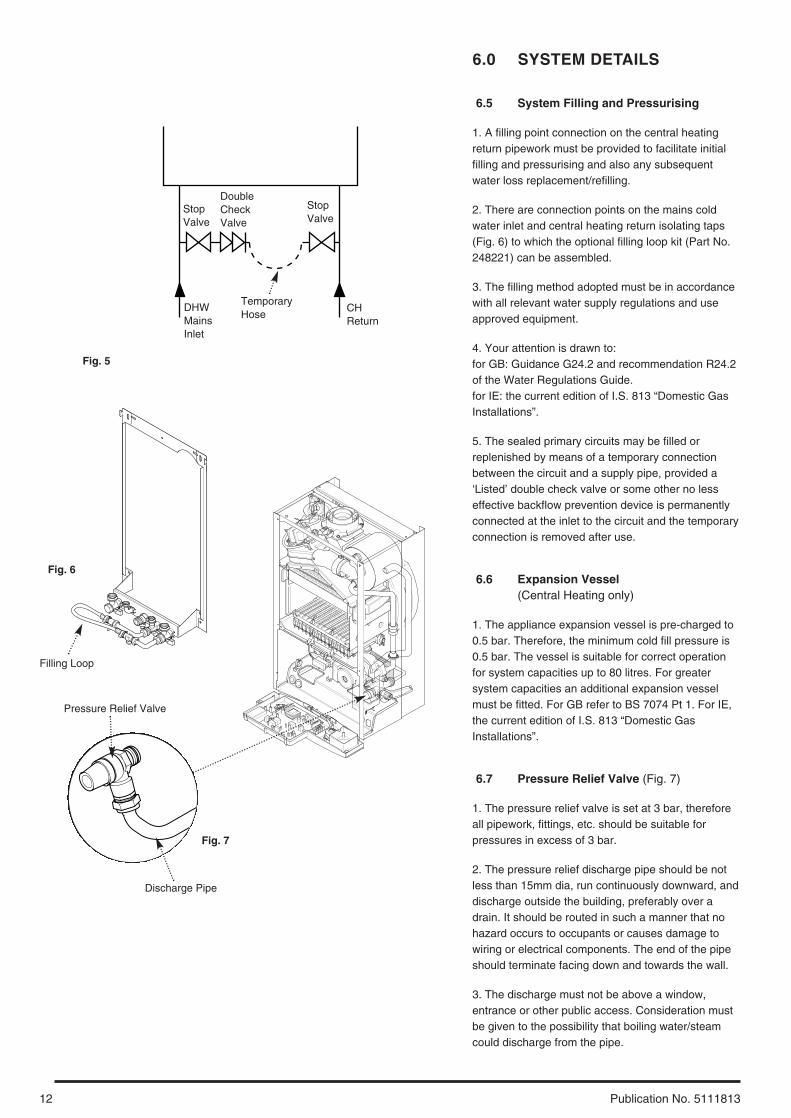
1. A filling point connection on the central heatingreturn pipework must be provided to facilitate initialfilling and pressurising and also any subsequentwater loss replacement/refilling.
2. There are connection points on the mains coldwater inlet and central heating return isolating taps(Fig. 6) to which the optional filling loop kit (Part No.248221) can be assembled.
3. The filling method adopted must be in accordancewith all relevant water supply regulations and useapproved equipment.
4. Your attention is drawn to: for GB: Guidance G24.2 and recommendation R24.2of the Water Regulations Guide. for IE: the current edition of I.S. 813 “Domestic GasInstallations”.
5. The sealed primary circuits may be filled orreplenished by means of a temporary connectionbetween the circuit and a supply pipe, provided a‘Listed’ double check valve or some other no lesseffective backflow prevention device is permanentlyconnected at the inlet to the circuit and the temporaryconnection is removed after use.
6.6 Expansion Vessel (Central Heating only)
1. The appliance expansion vessel is pre-charged to0.5 bar. Therefore, the minimum cold fill pressure is0.5 bar. The vessel is suitable for correct operationfor system capacities up to 80 litres. For greatersystem capacities an additional expansion vesselmust be fitted. For GB refer to BS 7074 Pt 1. For IE,the current edition of I.S. 813 “Domestic GasInstallations”.
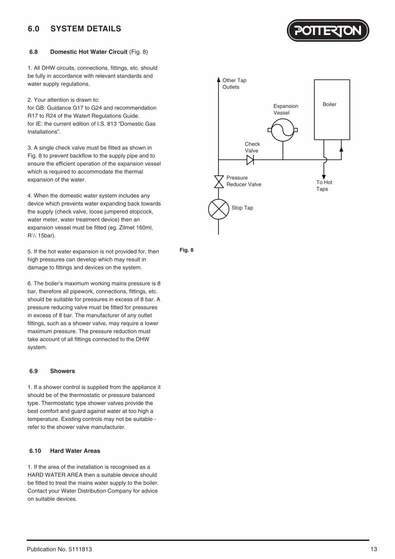
6.7 Pressure Relief Valve (Fig. 7)
1. The pressure relief valve is set at 3 bar, thereforeall pipework, fittings, etc. should be suitable forpressures in excess of 3 bar.
2. The pressure relief discharge pipe should be notless than 15mm dia, run continuously downward, anddischarge outside the building, preferably over adrain. It should be routed in such a manner that nohazard occurs to occupants or causes damage towiring or electrical components. The end of the pipeshould terminate facing down and towards the wall.
3. The discharge must not be above a window,entrance or other public access. Consideration mustbe given to the possibility that boiling water/steamcould discharge from the pipe.
Fig. 7
StopValve
DoubleCheckValve
DHWMainsInlet
CHReturn
TemporaryHose
Pressure Relief Valve
Filling Loop
Discharge Pipe
Fig. 5
Fig. 6
StopValve
13
6.0 SYSTEM DETAILS
Publication No. 5111813
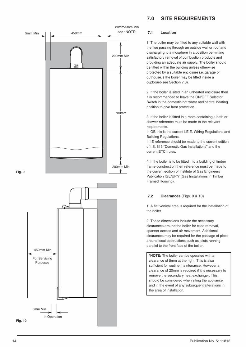
6.8 Domestic Hot Water Circuit (Fig. 8)
1. All DHW circuits, connections, fittings, etc. shouldbe fully in accordance with relevant standards andwater supply regulations.
2. Your attention is drawn to: for GB: Guidance G17 to G24 and recommendationR17 to R24 of the Watert Regulations Guide.for IE: the current edition of I.S. 813 “Domestic GasInstallations”.
3. A single check valve must be fitted as shown inFig. 8 to prevent backflow to the supply pipe and toensure the efficient operation of the expansion vesselwhich is required to accommodate the thermalexpansion of the water.
4. When the domestic water system includes anydevice which prevents water expanding back towardsthe supply (check valve, loose jumpered stopcock,water meter, water treatment device) then anexpansion vessel must be fitted (eg. Zilmet 160ml,R1/2 15bar).
5. If the hot water expansion is not provided for, thenhigh pressures can develop which may result indamage to fittings and devices on the system.
6. The boiler’s maximum working mains pressure is 8bar, therefore all pipework, connections, fittings, etc.should be suitable for pressures in excess of 8 bar. Apressure reducing valve must be fitted for pressuresin excess of 8 bar. The manufacturer of any outletfittings, such as a shower valve, may require a lowermaximum pressure. The pressure reduction musttake account of all fittings connected to the DHWsystem.
6.9 Showers
1. If a shower control is supplied from the appliance itshould be of the thermostatic or pressure balancedtype. Thermostatic type shower valves provide thebest comfort and guard against water at too high atemperature. Existing controls may not be suitable -refer to the shower valve manufacturer.
6.10 Hard Water Areas
1. If the area of the installation is recognised as aHARD WATER AREA then a suitable device shouldbe fitted to treat the mains water supply to the boiler.Contact your Water Distribution Company for adviceon suitable devices.
Boiler
Other TapOutlets
ExpansionVessel
To HotTaps
CheckValve
PressureReducer Valve
Stop Tap
Fig. 8
7.0 SITE REQUIREMENTS
14 Publication No. 5111813
7.1 Location
1. The boiler may be fitted to any suitable wall withthe flue passing through an outside wall or roof anddischarging to atmosphere in a position permittingsatisfactory removal of combustion products andproviding an adequate air supply. The boiler shouldbe fitted within the building unless otherwiseprotected by a suitable enclosure i.e. garage orouthouse. (The boiler may be fitted inside acupboard-see Section 7.3).
2. If the boiler is sited in an unheated enclosure thenit is recommended to leave the ON/OFF SelectorSwitch in the domestic hot water and central heatingposition to give frost protection.
3. If the boiler is fitted in a room containing a bath orshower reference must be made to the relevantrequirements.In GB this is the current I.E.E. Wiring Regulations andBuilding Regulations.In IE reference should be made to the current editionof I.S. 813 “Domestic Gas Installations” and thecurrent ETCI rules.
4. If the boiler is to be fitted into a building of timberframe construction then reference must be made tothe current edition of Institute of Gas EngineersPublication IGE/UP/7 (Gas Installations in TimberFramed Housing).
7.2 Clearances (Figs. 9 & 10)
1. A flat vertical area is required for the installation ofthe boiler.
2. These dimensions include the necessaryclearances around the boiler for case removal,spanner access and air movement. Additionalclearances may be required for the passage of pipesaround local obstructions such as joists runningparallel to the front face of the boiler.
*NOTE: The boiler can be operated with aclearance of 5mm at the right. This is alsosufficient for routine maintenance. However aclearance of 20mm is required if it is necessary toremove the secondary heat exchanger. Thisshould be considered when siting the applianceand in the event of any subsequent alterations inthe area of installation.
200mm Min
780mm
450mm
200mm Min
20mm/5mm Min
see *NOTE:5mm Min
5mm Min
450mm Min
For ServicingPurposes
Fig. 9
Fig. 10In Operation
15
7.0 SITE REQUIREMENTS
Publication No. 5111813
7.3 Ventilation of Compartments
1. Where the appliance is installed in a cupboard orcompartment, no air vents are required.
2. BS 5440: Part 2 Clause 4.2 refers to room sealedappliances installed in compartments. The appliancewill run sufficiently cool without ventilation.
7.4 Gas Supply
1. The gas installation should be in accordance withthe relevant standards. In GB this is BS 6891. In IEthis is the current edition of I.S. 813 “Domestic GasInstallations”.
2. The connection to the appliance is a 22mm coppertail located at the rear of the gas service cock (Fig. 11).
3. Ensure that the pipework from the meter to theappliance is of adequate size. Do not use pipes of asmaller diameter than the boiler gas connection(22mm).
7.5 Electrical Supply
1. External wiring must be correctly earthed,polarised and in accordance with relevantregulations/rules. In GB this is the current I.E.E.Wiring Regulations. In IE reference should be madeto the current edition of ETCI rules.
2. The mains supply is 230V ~ 50Hz fused at 3A.
NOTE: The method of connection to the electricitysupply must facilitate complete electrical isolationof the appliance.
Connection may be via a fused double-poleisolator with a contact separation of at least 3mmin all poles and servicing the boiler and systemcontrols only.
Fig. 11
Gas Service Cock
7.0 SITE REQUIREMENTS
16 Publication No. 5111813
7.6 Condensate Drain
FAILURE TO INSTALL THE CONDENSATEDISCHARGE PIPEWORK CORRECTLY WILL AFFECTTHE RELIABLE OPERATION OF THE BOILER
The condensate discharge pipe MUST NOT RISE atany point along its length. There MUST be a fall of ATLEAST 2.5° (50mm per metre) along the entire run.
1. The condensate outlet terminates in a 1” BSP nut andseal for the connection of 21.5mm (3/4in) plastic overflowpipe which should generally discharge internally into thehousehold drainage system. If this is not possible,discharge into an outside drain is acceptable.
2. Ensure the discharge of condensate complies withany national or local regulations in force. BS 6798:2000 & Part H1 of the Building Regulationsgive further guidance.
3. The discharge pipe should be run in a proprietarydrain pipe material e.g. PVC, PVC-U, ABS, PVC-C orPP.
4. Metal pipework is NOT suitable for use in condensatedischarge systems.
5. The pipe should be a minimum of 21.5mm diameterand must be supported using suitably spaced clips toprevent sagging.
6. Any pipe fitted externally must not exceed 3metres.
7. Any condensate discharge pipework external tothe building (or in an unheated part of it e.g. garage)must be insulated to protect against frost. It is alsorecommended that the pipe diameter is increased to32mm.
8. If the boiler is fitted in an unheated location the entirecondensate discharge pipe should be treated as anexternal run.
9. In all cases discharge pipe must be installed to aiddisposal of the condensate. To reduce the risk ofcondensate being trapped, as few bends and fittings aspossible should be used.
10. When discharging condensate into a soil stack orwaste pipe the effects of existing plumbing must beconsidered. If soil pipes or waste pipes are subjected tointernal pressure fluctuations when WC's are flushed orsinks emptied then back-pressure may force water out ofthe boiler trap and cause appliance lockout.
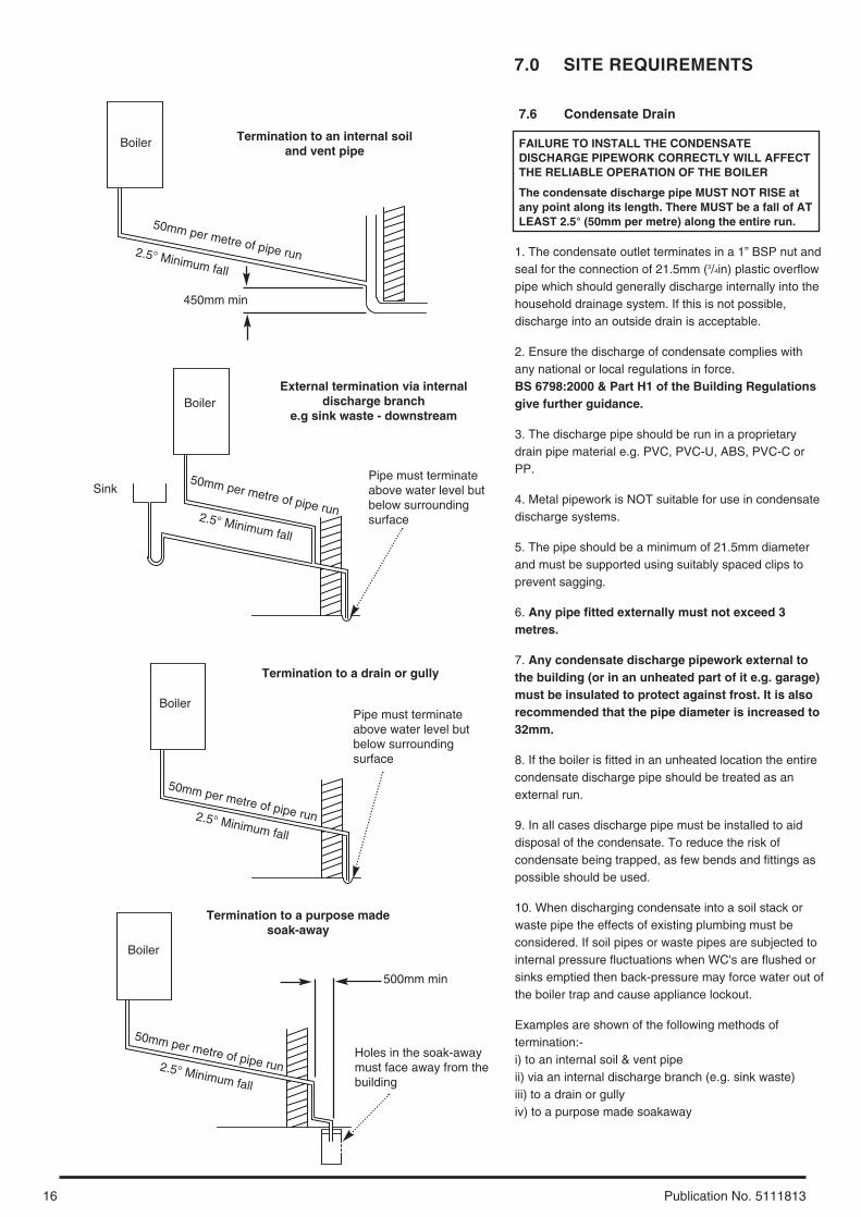
Examples are shown of the following methods oftermination:-i) to an internal soil & vent pipeii) via an internal discharge branch (e.g. sink waste)iii) to a drain or gullyiv) to a purpose made soakaway
Boiler
2.5° Minimum fall
Termination to an internal soiland vent pipe
450mm min
Boiler
2.5° Minimum fall
External termination via internaldischarge branch
e.g sink waste - downstream
SinkPipe must terminateabove water level butbelow surroundingsurface
BoilerPipe must terminateabove water level butbelow surroundingsurface
2.5° Minimum fall
Termination to a drain or gully
Boiler
500mm min
2.5° Minimum fall
Termination to a purpose madesoak-away
Holes in the soak-awaymust face away from thebuilding
50mm per metre of pipe run
50mm per metre of pipe run
50mm per metre of pipe run
50mm per metre of pipe run
17
7.0 SITE REQUIREMENTS
Publication No. 5111813
7.7 Flue
NOTE: Due to the nature of the boiler a plume ofwater vapour will be discharged from the flue. Thisshould be taken into account when siting the flueterminal.
1. The following guidelines indicate the generalrequirements for siting balanced flue terminals. ForGB recommendations are given in BS 5440 Pt 1. ForIE recommendations are given in the current editionof I.S. 813 “Domestic Gas Installations”.
2. If the terminal discharges onto a pathway orpassageway, check that combustion products will notcause a nuisance and that the terminal will notobstruct the passageway.
3. If a terminal is less than 2 metres above a balcony,above ground or above a flat roof to which peoplehave access, then a suitable terminal guard must beprovided.
Terminal Position with Minimum Distance (Fig. 12) (mm)
A* Directly below an openable window, air vent or any other ventilation opening. 300
B Below gutter, drain/soil pipe. 25C Below eaves. 25D Below a balcony/car port roof. 25E From vertical drain pipes and soil pipes. 25F From internal or external corners. 25G Above adjacent ground or balcony level. 300H From a surface facing a terminal. 600I Facing a terminals. 1200J From opening (door/window) in carport into dwelling. 1200K Vertically from a terminal on the same wall. 1500L Horizontally from a terminal on the same wall. 300M* Above an opening, air brick, opening window etc. 300N* Horizontally to an opening, air brick, opening window etc. 300
L
G
G
E
J
D
K
G
AA
D
F
H,I
B,C
F
Likely flue positions requiring a flue terminal guard
M
N
Fig. 12
300 minTerminalAssembly
Top View Rear Flue
Property Boundary LineFig. 13* In addition, the terminal should be no nearer than 150mm to anopening in the building fabric formed for the purpose ofaccommodating a built-in element such as a window frame. SeeBS 5440 Pt. 1.
7.0 SITE REQUIREMENTS
18 Publication No. 5111813
7.8 Flue Dimensions
The standard horizontal flue kit allows for flue lengthsbetween 100mm and 685mm from elbow to terminal(Fig. 14).
The maximum permissible equivalent flue lengthis: 4 metres.
NOTE: Each additional 45° of flue bend willaccount for an equivalent flue length of 0.5m.eg. 45° = 0.5m, 90° = 2 x 45° = 1m etc.
7.9 Flue Trim
1. The rubber flue trim supplied may be fitted to eitherthe outside wall or on the inner wall of installation.
7.10 Terminal Guard (Fig. 15)
1. When codes of practice dictate the use of terminalguards, they can be obtained from most Plumbers’and Builders’ Merchants.
2. There must be a clearance of at least 50mmbetween any part of the terminal and the guard.
3. When ordering a terminal guard, quote theappliance name and model number.
3. The flue terminal guard should be positionedcentrally over the terminal and fixed as illustrated.
Fig. 14
Fig. 15
100mm
685mm
19
7.0 SITE REQUIREMENTS
Publication No. 5111813
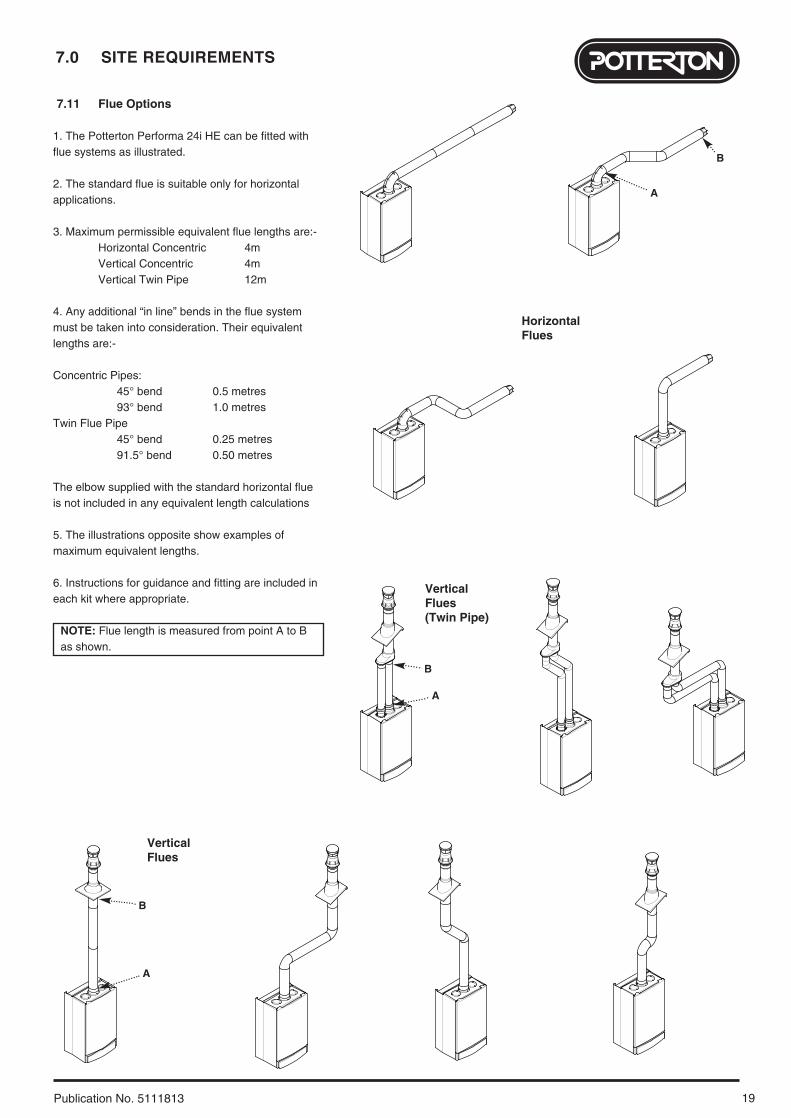
7.11 Flue Options
1. The Potterton Performa 24i HE can be fitted withflue systems as illustrated.
2. The standard flue is suitable only for horizontalapplications.
4. Any additional “in line” bends in the flue systemmust be taken into consideration. Their equivalentlengths are:-
Concentric Pipes:45° bend 0.5 metres93° bend 1.0 metres
Twin Flue Pipe45° bend 0.25 metres91.5° bend 0.50 metres
The elbow supplied with the standard horizontal flueis not included in any equivalent length calculations
5. The illustrations opposite show examples ofmaximum equivalent lengths.
6. Instructions for guidance and fitting are included ineach kit where appropriate.
NOTE: Flue length is measured from point A to Bas shown.
HorizontalFlues
VerticalFlues
VerticalFlues(Twin Pipe)
B
A
B
A
B
A
8.0 INSTALLATION
20 Publication No. 5111813
8.1 Initial Preparation
The gas supply, gas type and pressure must bechecked for suitability before connection (seeSection 7.4).
1. After considering the site requirements (see Section 7.0) position the fixing template on thewall ensuring it is level both horizontally andvertically.
2. Mark the position of the two most suitable fixingslots for the wall plate and boiler lower fixing holes. Itis preferable to use the horizontal fixing slots.
3. Mark the position of the centre of the flue hole(rear exit). For side flue exit, mark as shown (Fig. 16).
4. Note the shaded area on the template.Pipework cannot be routed upwards behind theboiler.
5. If required, mark the position of the gas and waterpipes. Remove the template.
6. Cut the hole for the flue (minimum diameter116mm).
7. Drill the wall as previously marked to accept thewall plugs supplied. Secure the wall plate using thefixing screws.
8. Using a spirit level ensure that the plate is levelbefore finally tightening the screws.
9. Connect the gas and water pipes to the valves onthe wall plate using the copper tails supplied. Ensurethat the sealing washers are fitted between theconnections.
8.2 Flushing
1. Connect a tube to the central heating flow or returnpipe (Fig. 17).
2. Flush thoroughly (see System Details, Section6.2).
3. The use of the optional Filling Loop Kit (Part No.248221) will simplify the flushing and soundnesschecking.
8.3 Preparing The Boiler
1. Remove all packaging.
2. Stand the boiler on its base by using the rear loweredge as a pivot.
NOTE: A small amount of water may drain from theboiler when the plastic caps are removed from theboiler connections.
Fig. 16
Fig. 17
190mm
For Side Flue Exit
Central Heating Return
Flushing TubeWall Plate
Filling Loop
21
8.0 INSTALLATION
Publication No. 5111813
8.4 Fitting The Boiler
1. Remove the sealing caps from the boilerconnections.
2. Lift the boiler using the lower edges. Engage theslots at the top rear of the boiler on the wall plate (Fig. 18).
3. Insert the sealing washers between the valves andpipes on the wall plate and the boiler connections. Therubber washers must be used on the gasconnection.
4. Tighten all the connections.
8.5 Fitting the Pressure Relief Discharge Pipe (Fig. 19)
1. Remove the discharge pipe from the kit.
2. Determine the routing of the discharge pipe in thevicinity of the boiler. Make up as much of the pipeworkas is practical, including the discharge pipe supplied.
3. The pipework must be at least 15mm diameter andrun continuously downwards to a discharge pointoutside the building. See section 6.7 for further details.
4. Utilising one of the sealing washers, connect thedischarge pipe to the adaptor and tighten the nut.
5. Complete the discharge pipework and route it to theoutside discharge point.
IMPORTANT: Make all soldered joints beforeconnecting to the pressure relief valve.
8.6 Condensate Drain (see section 7.6)
1. Connect the condensate drain using the 1” BSP nutand seal supplied.
Ensure the discharge of condensate complies withany national or local regulations in force (see BritishGas “Guidance Notes for the Installation ofDomestic Gas Condensing Boilers”.
2. The condensate outlet terminates in a 1” BSP nutand seal for the connection of 21.5mm (3/4in) plasticoverflow pipe which should generally dischargeinternally into the household drainage system. If this isnot possible, discharge into an outside drain isacceptable.
Fig. 19
Fig. 18
Pressure Relief Valve
Wall Plate
Discharge Pipe
8.0 INSTALLATION
22 Publication No. 5111813
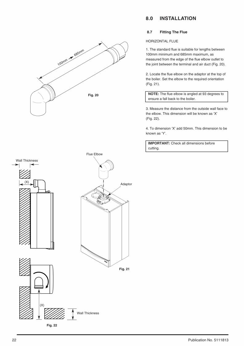
8.7 Fitting The Flue
HORIZONTAL FLUE
1. The standard flue is suitable for lengths between100mm minimum and 685mm maximum, asmeasured from the edge of the flue elbow outlet tothe joint between the terminal and air duct (Fig. 20).
2. Locate the flue elbow on the adaptor at the top ofthe boiler. Set the elbow to the required orientation(Fig. 21).
NOTE: The flue elbow is angled at 93 degrees toensure a fall back to the boiler.
3. Measure the distance from the outside wall face tothe elbow. This dimension will be known as ‘X’ (Fig. 22).
4. To dimension ‘X’ add 50mm. This dimension to beknown as ‘Y’.
IMPORTANT: Check all dimensions beforecutting.
Fig. 22
Wall Thickness
(X)
Wall Thickness
(X)
100mm
685mm
Flue Elbow
Fig. 20
Fig. 21
Adaptor
23
8.0 INSTALLATION
Publication No. 5111813
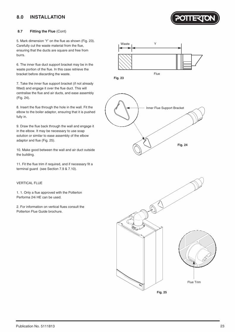
8.7 Fitting the Flue (Cont)
5. Mark dimension ‘Y’ on the flue as shown (Fig. 23).Carefully cut the waste material from the flue,ensuring that the ducts are square and free fromburrs.
6. The inner flue duct support bracket may be in thewaste portion of the flue. In this case retrieve thebracket before discarding the waste.
7. Take the inner flue support bracket (if not alreadyfitted) and engage it over the flue duct. This willcentralise the flue and air ducts, and ease assembly(Fig. 24).
8. Insert the flue through the hole in the wall. Fit theelbow to the boiler adaptor, ensuring that it is pushedfully in.
9. Draw the flue back through the wall and engage itin the elbow. It may be necessary to use soapsolution or similar to ease assembly of the elbowadaptor and flue (Fig. 25).
10. Make good between the wall and air duct outsidethe building.
11. Fit the flue trim if required, and if necessary fit aterminal guard (see Section 7.9 & 7.10).
VERTICAL FLUE
1. 1. Only a flue approved with the PottertonPerforma 24i HE can be used.
2. For information on vertical flues consult thePotterton Flue Guide brochure.
Flue Trim
Inner Flue Support Bracket
Y
Flue
Waste
Fig. 23
Fig. 24
Fig. 25
8.0 INSTALLATION
24 Publication No. 5111813
8.8 Making The Electrical Connections
To connect the mains input cable proceed asfollows:-
1. Slacken the facia panel securing screws and liftthe outercase panel so that its securing tabs areclear of the facia. Remove the panel.
2. Completely undo the screws securing the faciapanel and hinge it down (Fig. 26).
3. Remove the control box cover securing screws.Disengage the barbs on the control box from thecover. Remove the cover (Fig. 27).
4. Slacken the cable clamp on the LH side of theboiler chassis (Fig. 28). Insert the cable through theclamp and route it to the terminal block.
5. Slacken the screws in the terminal block, connectthe input cable, and tighten the screws.
6. If an external control is to be connected it can bedone at this point. Run the input cable from theexternal control through the second cable clamp onthe boiler chassis. Refer to the instructions suppliedwith the control.
7. To connect external control(s) remove the link between terminals 1 & 2. The 230V supply at terminal 1 can be connected to the external control. The switched output from the external control must be connected to terminal 2 (Fig. 29).
NOTE: If the room thermostat being usedincorporates an anticipator it MUST be wired asshown in Fig. 29
IMPORTANT: The external control MUST besuitable for 230V switching.
8. Ensure that both mains input and, where fitted,external control input cables have sufficient slack toallow the control box to drop down. Tighten the cableclamp(s) on the boiler chassis.
9. If the optional integral timer is to be used it shouldbe fitted at this point. Refer to the instructionssupplied with the timer. NOTE: An external frostthermostat cannot be used with the integral timer.
8.9 Preliminary Electrical Checks
1. Prior to commissioning the boiler preliminaryelectrical system checks should be carried out.
2. These should be performed using a suitablemeter, and include checks for Ground Continuity,Resistance to Ground, Short Circuit and Polarity.
Always fit fast blow 2A fuse
Fused supply 3A230V ~ 50Hz
Live (brown)
Neutral (blue)
Earth (green/yellow)
1
2
230V
br
b
g/y
bk
bk
b
br
bk
bk
g/y
1
N
L
Frost Thermostat
Room Thermostat
External Clock
2N
230 V
NL
SL
L230 V
Selector / Reset Switch
ExternalControls Nbr b
Pump
Hydraulic Differential Pressure Switchr
r
DHW Flow Priority Microswitchg
g
Safety Overheat Thermostat
Flue Thermostatb
b
Central HeatingNTC Sensor
r
r
Gas ValveSpark Electrode
Condensate Trap
Flame Sensing Electrode
Nbr b
Fan
bkbk
bbrbk
Pressure Switchbbr
bk
PCB
b
bbr
r
bk
bk
br
DHWNTC Sensor
g
g
Gas Valve Modulator
Fig. 28
Fig. 27
Fig. 29
Fig. 30
Fig. 26
Terminal Block
Fuse
Cable Clamp
Control Box Cover
Facia Panel
Functional Flow Diagram
Key to Wiringb - bluebr - brownbk - blackr - redg - green
IMPORTANT: If an integral timer is fitted to theboiler an external frost thermostat wired asshown will not operate correctly. Only externaltimers may be used in such installations, as inthe diagram.
25
9.0 COMMISSIONING
Publication No. 5111813
9.1 Commissioning the Boiler
1. Reference should be made to BS 5449 Section 5when commissioning the boiler.
2. Open the mains water supply to the boiler.
3. Open all hot water taps to purge the DHW system.
4. Ensure that the filling loop is connected and open,then open the heating flow and return valves on theboiler.
5. Open the screw on the automatic air vent (Fig. 31).
6. The system must be flushed in accordance with BS7593 (see Section 6.2) and the flushing agentmanufacturers instructions.
7. Pressurise the system to 1.0 bar then close anddisconnect the filling loop.
8. Turn the gas supply on and purge the systemaccording to in GB BS 6891 and in IE I.S. 813“Domestic Gas Installations”. BS 6891.
9. Test for gas soundness.
10. If at any time during commissioning it is requiredto terminate a particular cycle, e.g. the pump overrunperiod, turn the selector to the OFF position and thenback to either ( ) or ( ) (Fig. 33).
AutomaticAir Vent
PressureGauge
Screw
2
1
0 4
3
bar
Fig. 31
Selector Switch
Central Heating Temperature Control
Hot Water Temperature Control
Fig. 32
2
1
0 4
3
bar
30° 40° 50° 60° 70° 80°
Reset
Off
On Preheat
Pump
Fig. 33
Power OnNeon
9.0 COMMISSIONING
26 Publication No. 5111813
OU
T
MIN
Pressure Test Point Sealing Screw
Gas Valve
Fig. 34
9.2 Checking the Burner Pressure
1. Turn on the gas and electrical supplies to the boilerand ensure that all external controls are calling forheat.
2. Set the temperature control to maximum and theselector switch to the OFF position (Fig. 37).
3. Slacken the pressure test point sealing screw (Fig.34) on the gas valve and connect a pressure gauge.
4. Undo the screws securing the inner door panel. Liftthe panel slightly to disengage it from the studs ontop of the case and remove the panel.
5. Turn the selector switch fully anticlockwise againstthe spring pressure to the reset position and hold for2 seconds to reset the boiler.
6. Turn the selector switch to the Central Heating andDomestic Hot Water position ( ). The power ONneon ( ) will illuminate (Fig. 37).
7. Turn on a hot water tap to give a flow rate of atleast 10 l/min.
8. the pressure should be as quoted in Section 4.0Technical Data. If not, check that the gas supplypressure is correct (Natural Gas 20mbar, andPropane 37mbar).
9. The pressure can be adjusted if required.
10. To check and set minimum pressure first removeone of the modulator wires.
Adjusting the Pressure (Fig. 35)
11. Remove the plastic protection cap from thepressure adjustment nuts on the valve.
12. The smaller nut (5mm) adjusts minimum pressureand the larger nut (8mm) maximum pressure.
13. Using a suitable spanner adjust the relevant nutuntil the correct pressure is achieved.
14. Once the pressure has been set turn the boiler offand disconnect the pressure gauge.
15. Tighten the pressure test screw and refit themodulator to the valve. Reassemble in reverse order.
Selector Switch
Central Heating Temperature Control
Hot Water Temperature Control
2
1
0 4
3
bar
30° 40° 50° 60° 70° 80°
Reset
Off
On Preheat
Fig. 37
Power OnNeon
PressureGauge
2
1
0 4
3
bar
Fig. 36
Fig. 35
PlasticProtectionCap
ModulatorWire Maximum Rate
Adjustment NutMinimum RateAdjustment Nut
NOTE: Gas Valve ElectricalPlug/Igniter not shown for clarity
27
10.0 COMPLETION
Publication No. 5111813
10.1 Completion
1. Hinge the facia panel upwards and refit the casefront panel. Tighten the securing screws (Fig. 38).
2. Instruct the user in the operation of the boiler andsystem, explaining the operational sequence.
3. Carefully read and complete all sections of the“Benchmark” Installation, Commissioning andService Record Log Book that are relevant to theappliance and installation. The details of the LogBook will be required in the event of any warrantywork. The Log Book must be handed to the user forsafe keeping and each subsequent regular servicevisit recorded.
4. For IE, it is necessary to complete a “Declarationof Conformity” to indicate compliance with I.S. 813.An example of this is given in I.S. 813 “Domestic GasInstallations”. In addition it is necessary to completethe “Benchmark” Log Book.
5. Hand over the Users Operating, Installation andServicing Instructions and the Log Book, givingadvice on the necessity of regular servicing.
Fig. 38Facia Panel
Case Front Panel
11.0 SERVICING
28 Publication No. 5111813
11 .1 Annual Servicing
1. For reasons of safety and economy, it isrecommended that the boiler is serviced annually.Servicing must be performed by a competent person.
2. After servicing, complete the relevant section ofthe “Benchmark” Installation, Commissioning andService Record Log Book. This should be in thepossession of the user.
3. Ensure that the boiler is cool.
4. Ensure that both the gas and electricalsupplies to the boiler are isolated.
5. Slacken the screws securing the facia panel. Liftthe outercase panel so that its securing tabs areclear of the facia. Remove the panel (Fig. 39).
6. Remove the screws securing the inner door panel.Lift the panel slightly to disengage it from the studson top of the case (Fig. 40).
7. Note the positions of the three wires on the fanmotor and remove them. Remove the sensing tubefrom the fan spigot (Fig. 41).
8. Slacken the screws on the fan spigot outlet pipeclamps. Ease the clamps inwards over the pipe.
9. Draw the outlet pipe away from the boiler.
10. Remove the four screws securing the combustionbox door and remove the door (Fig. 40).
Case Front Panel
Fig. 39
Facia PanelSecuring Screws
CombustionBox Door
Inner DoorPanel
Fig. 40
Fan WiresFan
SensingTubes
Ease Fan Spigot OutletPipe Clamp Inwards
Fan Spigot Outlet Pipe
Fig. 41
29
11.0 SERVICING
Publication No. 5111813
11.1 Annual Servicing (Cont)
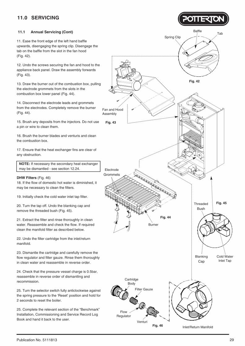
11. Ease the front edge of the left hand baffleupwards, disengaging the spring clip. Disengage thetab on the baffle from the slot in the fan hood (Fig. 42).
12. Undo the screws securing the fan and hood to theappliance back panel. Draw the assembly forwards(Fig. 43).
13. Draw the burner out of the combustion box, pullingthe electrode grommets from the slots in thecombustion box lower panel (Fig. 44).
14. Disconnect the electrode leads and grommetsfrom the electrodes. Completely remove the burner(Fig. 44).
15. Brush any deposits from the injectors. Do not usea pin or wire to clean them.
16. Brush the burner blades and venturis and cleanthe combustion box.
17. Ensure that the heat exchanger fins are clear ofany obstruction.
NOTE: If necessary the secondary heat exchangermay be dismantled - see section 12.24.
DHW Filters (Fig. 46)18. If the flow of domestic hot water is diminished, itmay be necessary to clean the filters.
19. Initially check the cold water inlet tap filter.
20. Turn the tap off. Undo the blanking cap andremove the threaded bush (Fig. 45).
21. Extract the filter and rinse thoroughly in cleanwater. Reassemble and check the flow. If requiredclean the manifold filter as described below.
22. Undo the filter cartridge from the inlet/returnmanifold.
23. Dismantle the cartridge and carefully remove theflow regulator and filter gauze. Rinse them thoroughlyin clean water and reassemble in reverse order.
24. Check that the pressure vessel charge is 0.5bar,reassemble in reverse order of dismantling andrecommission.
25. Turn the selector switch fully anticlockwise againstthe spring pressure to the ‘Reset’ position and hold for2 seconds to reset the boiler.
25. Complete the relevant section of the “Benchmark”Installation, Commissioning and Service Record LogBook and hand it back to the user.
Burner
Electrode
Grommets
Fig. 44
Fig. 46
CartridgeBody
Filter Gauze
FlowRegulator
Venturi
Inlet/Return Manifold
Cold WaterInlet Tap
Blanking
Cap
Threaded
Bush
Fig. 45
Spring Clip
Fan and HoodAssembly
BaffleTab
Fig. 42
Fig. 43
12.0 CHANGING COMPONENTS
30 Publication No. 5111813
IMPORTANT: When changing componentsensure that both the gas and electrical supplies tothe boiler are isolated before any work is started.When the component has been changed turn theselector switch fully anticlockwise against thespring pressure to the reset position and hold for 2seconds to reset the boiler beforerecommissioning.
See Section 11.1 “Annual Servicing” for removal ofcase panel, door etc.
12.1 Fan (Figs. 48 & 49)
1. Note the positions of the three wires on the fanmotor and remove them. Remove the sensing tubefrom the fan spigot.
2. Slacken the screws on the fan spigot outlet pipeclamps. Ease the clamps inwards over the pipe.
3. Draw the outlet pipe away from the boiler.
4. Remove the four screws securing the combustionbox door and remove the door.
5. Ease the front edge of the left hand baffle upwards,disengaging the spring clip. Disengage the tab on thebaffle from the slot in the fan hood.
6. Undo the screws securing the fan hood to theappliance back panel, and draw the fan and hoodassembly forwards.
7. Remove the screws and spring washers securingthe fan to the hood.
8. Fit the new fan to the hood using the screws andspring washers previously removed.
9. Reassemble in reverse order of dismantling.
12.2 Pressure Switch (Fig. 47)
1. Remove the fan as described in section 12.1.
2. Note the positions of the two sensing tubes andthree wires and remove them.
3. Remove the two screws holding the pressureswitch to the bracket on the combustion box toppanel.
4. Fit the new pressure switch and reassemble allcomponents in reverse order of dismantling.
PressureSwitch
SensingTubes
Pressure Switch Wires
Fig. 47b
br
H+’ve
L-’ve
Fan Hood
Spring Washer
Securing Screw
Fan WiresFan
SensingTubes
Ease Fan Spigot OutletPipe Clamp Inwards
Fan Spigot Outlet Pipe
Spring Clip
BaffleTab
Fan
Fig. 48
Fig. 49
31
12.0 CHANGING COMPONENTS
Publication No. 5111813
12.3 Heat Exchanger (Fig. 50)
1. Remove the fan as described in section 12.1.
2. Drain the primary circuit. Prise the pipe connectingclips off the joints in the flow and return pipes.Remove the heat exchanger return pipe.
3. Lift the heat exchanger to disconnect the flow pipejoint. Withdraw it from the appliance, taking care not todamage the rear insulation piece.
4. Fit the new heat exchanger.
5. Reassemble in reverse order of dismantling, andrepressurise the system.
12.4 Burner (Fig. 51)
1. Remove the four screws securing the combustionbox door and remove the door.
2. Draw the burner out of the combustion box, pullingthe electrode grommets from the slots in thecombustion box lower panel.
3. Disconnect the electrode leads and grommets fromthe electrodes. Completely remove the burner.
4. Undo the screws securing the electrodes to theburner. Examine the condition of the electrodes,replacing if necessary. Fit the electrodes to the newburner.
5. Engage the burner location brackets over the studson the injector manifold and reassemble in reverseorder.
Burner
ElectrodeGrommets
Electrode Leads
Electrodes
Fig. 50
Heat Exchanger
Pipe ConnectingClips
Fig. 51
12.0 CHANGING COMPONENTS
32 Publication No. 5111813
12.5 Injectors (Fig. 52)
1. Remove the burner as described in Section 12.4.
2. Undo the screws securing the injector manifold tothe inlet elbow and remove the manifold.
3. Unscrew and replace injectors as required andexamine the sealing gasket, replacing as necessary.Reassemble in reverse order.
12.6 Electrodes (Fig. 52)
1. Remove the four screws securing the combustionbox door and remove the door.
2. Undo the screws securing the burner to theinjector manifold. Draw the burner out of thecombustion box, pulling the electrode grommets fromthe slots in the combustion box lower panel.
3. Disconnect the lead and grommet from theelectrode being replaced. Undo the securing screwand withdraw the electrode to the burner.
4. Reassemble in reverse order.
12.7 Insulation (Fig. 53)
1. Remove the four screws securing the combustionbox door and remove the door.
2. Slide the side insulation pieces carefully out oftheir carriers.
3. To replace the rear insulation piece it is necessaryto remove the heat exchanger as described inSection 12.3 and slide out the side pieces.
4. The combustion box door insulation piece can bereplaced by carefully bending up the two retainingtabs.
5. Replace all insulation pieces and reassemble inreverse order.
13.8
InjectorManifold
Inlet Elbow
Gasket
Injector
Burner
ElectrodeGrommets
Electrode Leads
Side Insulation
Rear Insulation
Front Insulation
CombustionBox Door
Side Insulation
Electrodes
Fig. 52
Fig. 53
33
12.0 CHANGING COMPONENTS
Publication No. 5111813
12.8 Gas Valve (Fig. 54)
1. Undo the nut on the gas feed pipe under the boiler.
2. Completely undo the securing screws and hingethe facia panel down.
3. Disconnect the wires from the valve modulator andthe ignition lead from the spark generator. Disconnectthe pressure sensing pipe from the valve. Undo thescrew securing the spark generator electrical plug tothe valve and disconnect the plug.
4. Pull the earth wire off the spade terminal on thevalve.
5. Remove the screws securing the inlet pipe flangeto the boiler bottom panel and those securing theoutlet manifold to the burner manifold.
6. Remove the valve from the boiler.
7. Note the orientation of the inlet pipe and outletmanifold. Undo the securing screws and remove thepipe and manifold.
8. Examine the ‘O’ ring seals for damage, replacingas necessary.
9. Fit the inlet pipe and outlet manifold to the newvalve, ensuring that the ‘O’ ring seals are in place.
10. Reassemble in reverse order and check theburner pressure (Section 9.2).
12.9 Central Heating Temperature Sensor (Fig. 55)
1. Ease the retaining tab on the sensor away anddisconnect the electrical plug.
2. Unscrew the sensor from it’s pocket andreassemble in reverse order. The electrical plug willonly fit one way.
12.10 Safety Thermostat (Fig. 55)
1. Pull the electrical connections off the thermostat.
2. Remove the screws securing the thermostat to themounting plate on the flow pipe.
3. Reassemble in reverse order. The thermostat is notpolarised - either wire can fit either terminal on thethermostat.
12.11 DHW Temperature Sensor (Fig. 56)
1. Turn off the mains water supply and draw off theresidual domestic hot water.
2. Ease the retaining tab on the sensor away anddisconnect the electrical plug.
3. Unscrew the sensor from the plate heat exchangermanifold. Examine the sealing washer,replacing ifnecessary.
4. Reassemble in reverse order. The electrical plugwill only fit one way.
Gas Valve
Inlet Pipe
Gas FeedPipe
ElectricalPlug
Central HeatingTemperature Sensor
SafetyThermostat
Flow Pipe
Fig. 54
Fig. 55
DHW TemperatureSensor
Fig. 56
Plate HeatExchanger
ModulatorWires
Ignition
Lead
Earth Wire
12.0 CHANGING COMPONENTS
34 Publication No. 5111813
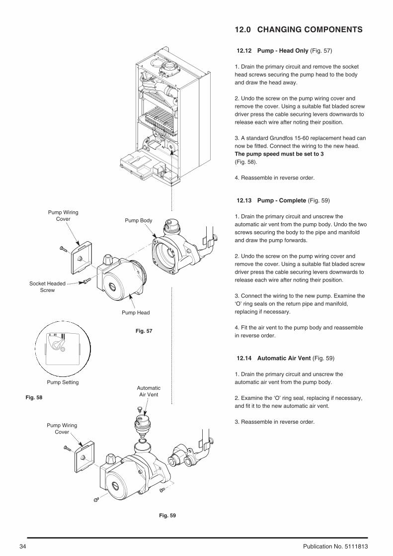
12.12 Pump - Head Only (Fig. 57)
1. Drain the primary circuit and remove the sockethead screws securing the pump head to the bodyand draw the head away.
2. Undo the screw on the pump wiring cover andremove the cover. Using a suitable flat bladed screwdriver press the cable securing levers downwards torelease each wire after noting their position.
3. A standard Grundfos 15-60 replacement head cannow be fitted. Connect the wiring to the new head.The pump speed must be set to 3(Fig. 58).
4. Reassemble in reverse order.
12.13 Pump - Complete (Fig. 59)
1. Drain the primary circuit and unscrew theautomatic air vent from the pump body. Undo the twoscrews securing the body to the pipe and manifoldand draw the pump forwards.
2. Undo the screw on the pump wiring cover andremove the cover. Using a suitable flat bladed screwdriver press the cable securing levers downwards torelease each wire after noting their position.
3. Connect the wiring to the new pump. Examine the‘O’ ring seals on the return pipe and manifold,replacing if necessary.
4. Fit the air vent to the pump body and reassemblein reverse order.
12.14 Automatic Air Vent (Fig. 59)
1. Drain the primary circuit and unscrew theautomatic air vent from the pump body.
2. Examine the ‘O’ ring seal, replacing if necessary,and fit it to the new automatic air vent.
3. Reassemble in reverse order.
Pump Setting
Pump WiringCover
Socket HeadedScrew
Pump Head
Pump Body
Pump WiringCover
AutomaticAir Vent
Fig. 57
Fig. 59
Fig. 58
35
12.0 CHANGING COMPONENTS
Publication No. 5111813
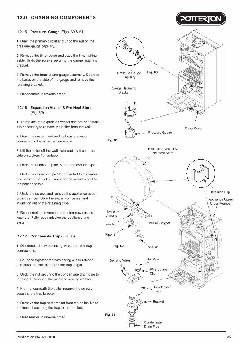
12.15 Pressure Gauge (Figs. 60 & 61)
1. Drain the primary circuit and undo the nut on thepressure gauge capillary.
2. Remove the timer cover and ease the timer wiringaside. Undo the screws securing the gauge retainingbracket.
3. Remove the bracket and gauge assembly. Depressthe barbs on the side of the gauge and remove theretaining bracket.
4. Reassemble in reverse order.
12.16 Expansion Vessel & Pre-Heat Store (Fig. 62)
1. To replace the expansion vessel and pre-heat storeit is necessary to remove the boiler from the wall.
2. Drain the system and undo all gas and waterconnections. Remove the flue elbow.
3. Lift the boiler off the wall plate and lay it on eitherside on a clean flat surface.
4. Undo the unions on pipe ‘A’ and remove the pipe.
5. Undo the union on pipe ‘B’ connected to the vesseland remove the locknut securing the vessel spigot tothe boiler chassis.
6. Undo the screws and remove the appliance uppercross member. Slide the expansion vessel andinsulation out of the retaining clips.
7. Reassemble in reverse order using new sealingwashers. Fully recommission the appliance andsystem.
12.17 Condensate Trap (Fig. 63)
1. Disconnect the two sensing wires from the trapconnections.
2. Squeeze together the wire spring clip to releaseand ease the inlet pipe from the trap spigot.
3. Undo the nut securing the condensate drain pipe tothe trap. Disconnect the pipe and sealing washer.
4. From underneath the boiler reomve the screwssecuring the trap bracket.
5. Remove the trap and bracket from the boiler. Undothe locknut securing the trap to the bracket.
6. Reassemble in reverse order.
Pressure GaugeTimer Cover
Pressure GaugeCapillary
Gauge RetainingBracket
Expansion Vessel &Pre-Heat Store
Retaining Clip
Appliance UpperCross Member
Vessel Spigots
BoilerChassis
Lock Nut
Fig. 60
Fig. 61
Fig. 62
Pipe ‘B’
Pipe ‘A’
Inlet PipeSensing Wires
CondensateTrap
Wire SpringClip
Bracket
CondensateDrain Pipe
Fig. 63
12.0 CHANGING COMPONENTS
36 Publication No. 5111813
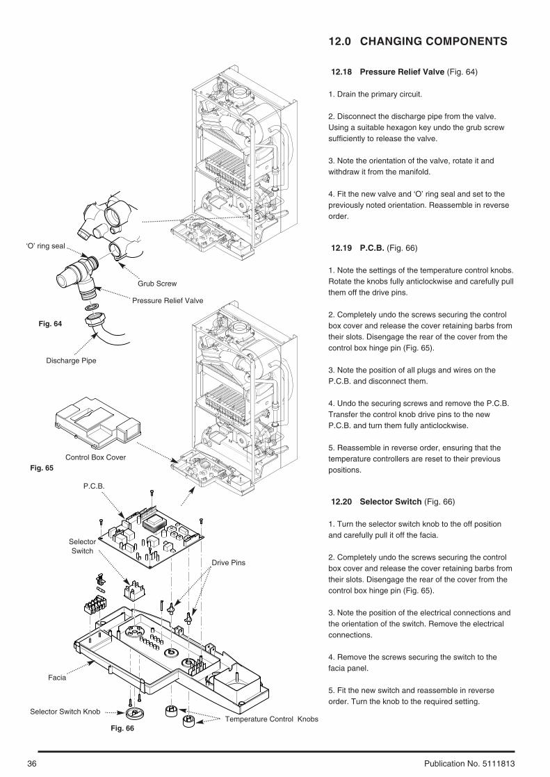
12.18 Pressure Relief Valve (Fig. 64)
1. Drain the primary circuit.
2. Disconnect the discharge pipe from the valve.Using a suitable hexagon key undo the grub screwsufficiently to release the valve.
3. Note the orientation of the valve, rotate it andwithdraw it from the manifold.
4. Fit the new valve and ‘O’ ring seal and set to thepreviously noted orientation. Reassemble in reverseorder.
12.19 P.C.B. (Fig. 66)
1. Note the settings of the temperature control knobs.Rotate the knobs fully anticlockwise and carefully pullthem off the drive pins.
2. Completely undo the screws securing the controlbox cover and release the cover retaining barbs fromtheir slots. Disengage the rear of the cover from thecontrol box hinge pin (Fig. 65).
3. Note the position of all plugs and wires on theP.C.B. and disconnect them.
4. Undo the securing screws and remove the P.C.B.Transfer the control knob drive pins to the newP.C.B. and turn them fully anticlockwise.
5. Reassemble in reverse order, ensuring that thetemperature controllers are reset to their previouspositions.
12.20 Selector Switch (Fig. 66)
1. Turn the selector switch knob to the off positionand carefully pull it off the facia.
2. Completely undo the screws securing the controlbox cover and release the cover retaining barbs fromtheir slots. Disengage the rear of the cover from thecontrol box hinge pin (Fig. 65).
3. Note the position of the electrical connections andthe orientation of the switch. Remove the electricalconnections.
4. Remove the screws securing the switch to thefacia panel.
5. Fit the new switch and reassemble in reverseorder. Turn the knob to the required setting.
Pressure Relief Valve
Grub Screw
‘O’ ring seal
Discharge Pipe
Control Box Cover
P.C.B.
SelectorSwitch
Facia
Selector Switch KnobTemperature Control Knobs
Fig. 64
Fig. 65
Fig. 66
Drive Pins
37
12.0 CHANGING COMPONENTS
Publication No. 5111813
12.21 Plate Heat Exchanger (Fig. 67)
1. Drain the primary circuit.
2. While supporting the heat exchanger undo thescrews securing it to the brass manifolds.
3. Withdraw the heat exchanger upwards and to theleft of the gas valve, taking care not to damage anywires or controls.
Seals4. There are four rubber seals between the manifoldsand heat exchanger which may require replacement.
5. Ease the seals out of the manifolds. Replacecarefully, ensuring that when the seal is inserted intothe manifold it is parallel and pushed fully in.
6. When fitting the new heat exchanger note that theleft hand location stud is offset towards the centremore than the right hand one.
7. Reassemble in reverse order.
12.22 Diverter Valve Assembly (Figs. 68 & 69)
The diverter valve assembly comprises of a centralheating pressure differential valve and a domestic hotwater pressure differential valve. These areconnected to a manifold which is joined to the plateheat exchanger.
1. Isolate the boiler from the central heating flow andreturn pipes and drain the boiler primary circuit.
2. Prise off the spring clip retaining the microswitch.Pull the switch away.
3. Undo the screws securing the differential valvecover.
4. Carefully draw off the cover and remove thediaphragm.
5. Fit the new diaphragm and reassemble in reverseorder.
Diverter Valve Operating Head (Fig. 70)
1. Pull the 3-pin plug off the operating head and priseoff the spring clip retaining the head to the valvebody.
2. Lift the operating head away from the valve body.
3. Fit the new head and reassemble in reverse order.
12.23 Flow Regulator (Figs. 71 & 72)
1. Undo the filter cartridge from the inlet/returnmanifold.
2. Unscrew the venturi and remove the flowregulator.
3. Check the cleanliness of the filter gauze, rinsingthoroughly in clean water as necessary. Fit the newflow regulator and reassemble in reverse order.
Fig. 70
CartridgeBody
Filter Gauze
FlowRegulator
Venturi
Inlet/Return Manifold
Fig. 71
Fig. 72
Diverter Valve
Microswitch
Diverter ValveOperating Head
3-pin Plug
Pushrod
DiaphragmSpring
Diaphragm
Spring Clip
CH PressureDifferential Valve
Cover
Spring Clip
39
12.0 CHANGING COMPONENTS
Publication No. 5111813
12.24 Secondary Heat Exchanger (Fig. 73)
1. Drain the primary circuit
2. Undo the four screws securing the right hand casepanel. Remove the panel.
3. Prise the connecting clips from the heat exchangerreturn pipe and the boiler return pipe. Remove thepipes.
4. Slacken the screws on the left hand fan spigot outletpipe clamp. Ease the clamp to the right.
5. Remove the nut securing the elbow to thesecondary heat exchanger. Draw the elbow and outletpipe forwards.
6. Remove the secondary heat exchanger from theouter drum by easing it forward.
7. Reassemble in reverse order of dismantling.
12.25 Flue Overheat Thermostat (Fig. 74)
NOTE: The flue overheat thermostat includes areset button. Check that the thermostat will notreset before replacing.
1. Remove the fan spigot outlet pipe from the fan andelbow.
2. Pull the two wires off the terminals on the flueoverheat thermostat. Unscrew the thermostat from theadaptor in the outlet elbow.
3. Reassemble in reverse order of dismantling.
Ease Fan Spigot OutletPipe Clamp Inwards
Fan Spigot Outlet Pipe
Overheat Thermostat
Fan Spigot OutletPipe Clamp
Fan Outlet Pipe
Secondary Heat Exchanger
Outer Drum
Boiler Return Pipe
Pipe Connecting Clip
ElbowHeat ExchangerReturn Pipe
Fig. 73
Fig. 74
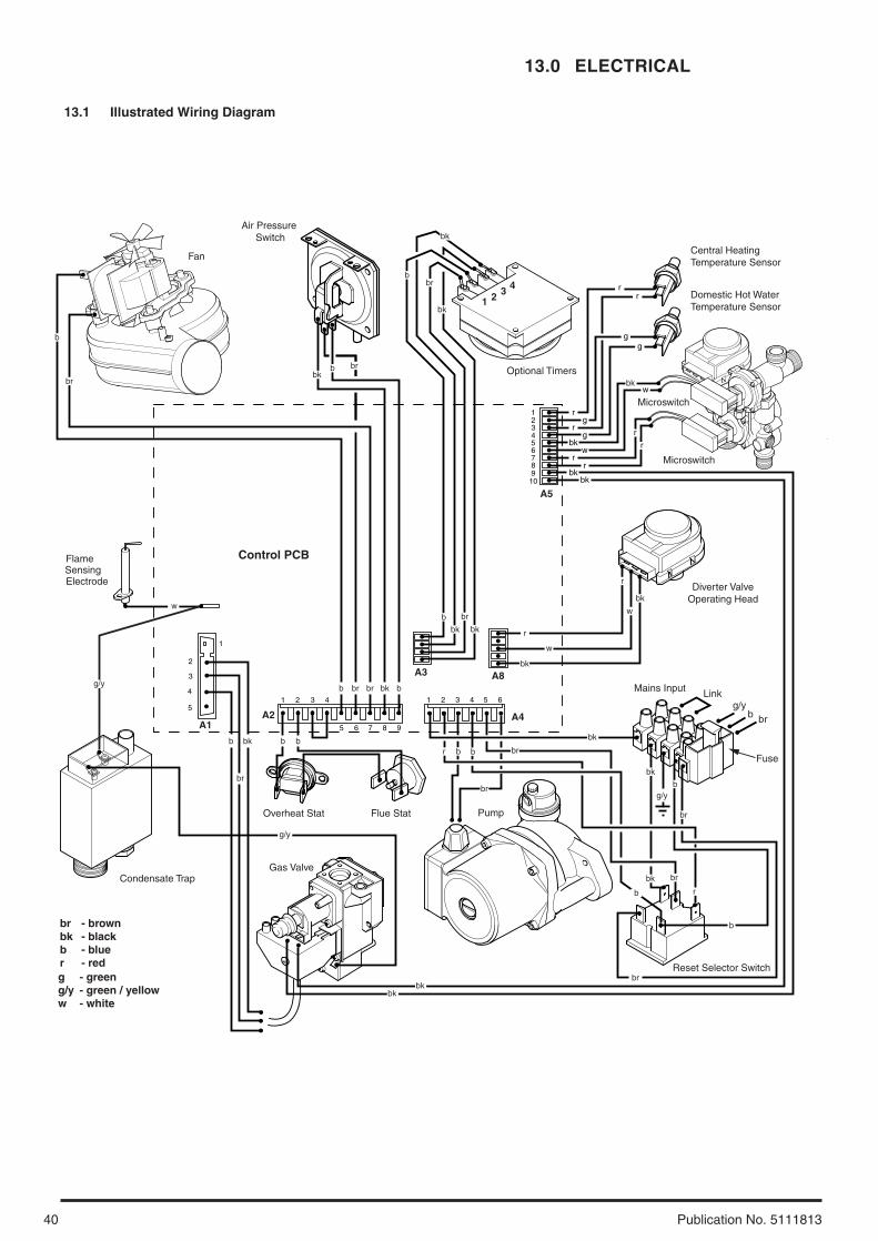
13.0 ELECTRICAL
40 Publication No. 5111813
- brown- black- blue- red
brbkbr
- green- green / yellow- white
gg/yw
Optional Timers
Domestic Hot Water Temperature Sensor
Reset Selector Switch
Control PCB
1
bkbk
rr
wbk
gr
gr
2
1
2
3
3
4 1 2 3 4 5 6
10987654321
4
5
5
6 7 8 9
Central Heating Temperature Sensor
Fan
Gas Valve
Overheat Stat
Microswitch
Air Pressure Switch
Flame
Mains Input
Fuse
Linkg/y
b br
br
b
g/y
SensingElectrode
bb
bbkb b
bkbrbr
Flue Stat
br
Microswitch
Pump
Diverter ValveOperating Head
bk bk
w
bk
r
b br
br
bk
br
b
brbbk
b
bk
br
bk
b br
bk
w
r
br
b
bk
br
b
bk br
r
bkbk
w
A5
A4
A8A3
A2A1
1 2 3 4 rr
gg
bkw
r
r
Condensate Trap
g/y
g/y
13.1 Illustrated Wiring Diagram
41
14.0 SHORT PARTS LIST
Publication No. 5111813
Short Parts List
Key G.C. Description ManufacturersNo. No. Part No.
22 Fan 5112627
23 Pressure Switch 5112999
32 Heat Exchanger 5112431
41 Burner 5112770
44 Injector 1.18 NG 248210
59 E66 408 Electrode Lead 248037
63 E66 411 Spark or Sensing
Electrode 247384
72 E66 539 Pump Complete 248042
131 342 571 Temperature Sensor 247394
135 E66 439 Safety Thermostat 248079
140 Gas Valve 5107339
154 PCB 248731
169 E66 453 Pressure Gauge 248090
387 E68 349 Motor-3way Valve 248733
390 E68 350 Differential Valve-DHW 248734
371 Igniter/Gas Valve
Cable 5112385
A Flue Overheat
Thermostat 5112395
22 140
44
63
154
72
135
59
41
169
131
23
32
390
387
A
371
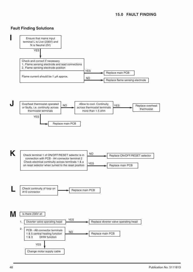
15.0 FAULT FINDING
42 Publication No. 5111813
Carry out initial fault finding checks1. Check that gas, water and electrical supplies are available at the boiler. Electrical supply = 230V ~ 50 Hz.
CH water system pressurised to 0.5 bar when the boiler is cold. The preferred minimum gas pressure is 19.5mbar (natural gas), 27mbar (butane) or 36mbar (propane).
2. Carry out electrical system checks, i.e. Ground Continuity, Resistance to Ground, Short Circuit and Polarity with a suitable meter. NOTE: These checks must be repeated after any servicing or fault finding.
3. Ensure all external controls are calling for heat and check all external and internal fuses. Before any servicing or replacement of parts ensure the gas and electrical supplies are isolated.
Refer to Section 13.1 “Illustrated Wiring Diagram” for position of numbered terminalsDomestic Hot Water - Preheating Function - Follow operational sequence
Turn On/Off/Reset selectorto position.
neon illuminated.
Turn preheat control to on.Preheating function startsafter 25 seconds.
neon flashing.
Primary water diverted toDHW preheating circuit.
Pump runs.
Primary flow switchoperated.
Fan runs at maximumspeed.
Air pressure switch proved.
Spark at ignition electrodefor up to 10 seconds.
Burner lights.
Burner output modulates tominimum heat input until atemperature of 75°C isdetected by central heatingNTC sensor.
Burner extinguishes.
Go to section ‘A’.
External controls andwhere fitted, integral timer
calling for heat.Go to section ‘L’.
Ensure controls are set todemand and verify thecontacts are closed.
Go to section ‘M’.
neon flashing.Go to section ‘B’.
neon flashing.Go to section ‘C’.
neon flashing.Turn the selector to reset.
neon flashing.Go to section ‘D’.
Go to section ‘J’.
neon flashing.Go to section ‘E’.
neon flashing.
Turn selector to the resetposition. If the neon does
not extinguish go tosections H and K.
Change main PCB.
Burner extinguishes after10 seconds.
Go to section ‘F’.
neon flashing.Go to section ‘I’.
Go to section ‘G’.
Fan stops. Pump continues torun for 30 seconds.
Operationsequence correct
YES
NO
YES
YES
YES
YES
YES
YES
YES
YES
YES
NO
NO
NO
NO
NO
NO
NO
NO
NO
NO
YES
NO
YES YES YES
NO
YES
NO
YES
NOTE: When instructed to turn the Selectorto the reset position turn the Selector Switchfully anticlockwise against the springpressure and hold for 2 seconds to reset theboiler.
43
15.0 FAULT FINDING
Publication No. 5111813
Domestic Hot Water - Follow operational sequence
Primary flow switchoperated
Fan runs at max speed.
Pump runs
Turn preheat control to on.Preheating function starts
after 25 seconds.neon flashing.
Primary water is divertedfrom preheating circuit to
DHW heat exchanger.neon illuminated
Air pressure switch proved.
neon flashingSpark at ignition electrode
for up to 10 seconds.
neon flashingGo to section ‘B’
neon flashingGo to section ‘C’
neons flashingGo to section ‘D’
neon flashingGo to section ‘I’
Turn the selector to reset.If regular resetting is
required or appliance stilldoes not operate
investigation is necessary.
neon flashingGo to section ‘E’
YES
YES
YES
NO
Turn On/Off/Reset selectorto position.
neon illuminated.
Primary water diverted toDHW preheating circuit.
Open DHW tap fully. DHWflow switch operated.
Burner lights.
Burner output modulates tomaintain temperature set at
preheat control.
Burner goes out.
Burner extinguishes after10 seconds.
NO
Close DHW tap.
DHW flow valve senses noflow. DHW flow switch
released off.
Preheating functionrestarts.
neon flashing
Go to section ‘A’.
Go to section ‘M’.
External controls andwhere fitted, integral timer
calling for heat.
Go to section ‘L’.
Ensure controls are set todemand and verify thecontacts are closed.
DHW flow rate more than2.5 l/min.
Is mains water filter anddifferential assembly
clean?
DHW flow valve diaphragmdamaged.
Replace diaphragm.
DHW flow valve rodobstructed.
Continuity across DHW flowmicroswitch terminals and
PCB - A5 connectorterminals 5 & 6
Replace DHW flowmicroswitch.
Replace main PCB
Go to section ‘J’.
Turn selector to the resetposition. If the neon does
not extinguish go tosections H and K.
Change main PCB.
Go to section ‘F’.
Reduce the DHW flow rate.If burner does not modulate
clean DHW temperaturesensor and DHW heat
exchanger. If modulationdoes not occur go to
section ‘G’.
External controls and wherefitted, integral timer calling
for heat.
Fan stops.Pump continues torun for 30 seconds.
Operationsequence correct
Ensure controls are set todemand and verify the
controls are closed.
Go to section ‘L’.
YES
NO
NO
YES
NO
NO
YES
YES YES
YES
YES
NONO
YES
YESNO
NO
YES
YES
NO
YES
NO
NO
YES
NO
NO
YESYES
NO
NO
YES
YES
YES NO
YES
YESYES YES YES
neon flashingNO
YES
NO
15.0 FAULT FINDING
44 Publication No. 5111813
Turn selector to neon illuminated.
Turn Central Heatingthermostat to maximum.
neon illuminated.
Go to section ‘A’.
neon flashingGo to section ‘B’.
External controls calling forheat and where fitted,
internal clock calling forheat.
Ensure controls are set todemand and verify thecontacts are closed.
NO
Central Heating - Follow operational sequence
Primary water is divertedfrom preheating circuit to
CH system.neon illuminated.
Primary flow switchoperated.
Pump runs.
Fan runs at max speed.
Air pressure switch proved.
Spark at ignition electrodesfor up to 10 seconds.
neon illuminated
Burner extinguishes after10 seconds.
Preheating function startsafter 25 seconds.
neon flashing(see DHW preheating
function).
Primary water is divertedfrom preheating circuit to
CH system.neon illuminated
Go to section ‘M’.
neon flashingGo to section ‘B’.
neon flashingGo to section ‘C’.
neons flashingGo to section ‘D’.
Turn the selector to reset.If regular resetting is
required or appliance stilldoes not operate
investigation is necessary.
Go to section ‘J’.
NO
YES
neon flashingGo to section ‘E’.
neon flashing
Turn selector to the resetposition. If the neon does
not extinguish go tosections H and K.
Change main PCB.
Go to section ‘F’.
neon flashingGo to section ‘I’
Preheat control is not atminimum position. External
control calling for heat.Go to section ‘L’.
Go to section ‘M’.
YES
NO YES
NO
YES
NO
YESNO
YES
NO
YES
YES
YES
NO
NO NO
YES
YESNO
YES
NO
NO
YES
NO
YES
neon flashingNO
Go to next page
YES
45
15.0 FAULT FINDING
Publication No. 5111813
Burner output modulatesuntil set temperature is
reached.
Burner goes out. Fan stops.Pump continues to run
for 3 minutes. (room thermostat open)
Operationsequence correct
Go to section ‘G’.
YES
NO
YES YES YES
CH temperature higherthan set point of CH
thermostat control. WhenCH temperature decreases
cycle continues.
Central Heating - Follow operational sequence (Continued)
Fan runs at max speed.
Air pressure switch proved.
Spark at ignition electrodesfor up to 10 seconds.
neon illuminated
Burner extinguishes after10 seconds.
neons flashingGo to section ‘D’.
Turn the selector to reset.If regular resetting is
required or appliance stilldoes not operate
investigation is necessary.
Go to section ‘J’.
NO
YES
neon flashingGo to section ‘E’.
neon flashing
Turn selector to the resetposition. If the neon does
not extinguish go tosections H and K.
Change main PCB.
Go to section ‘F’.
neon flashingGo to section ‘I’
YES
YES
NO
NO NO
YES
YESNO
YES
NO
neon flashingNO
Does the burner remain lit ?
NO
Continued fromprevious page
YES
15.0 FAULT FINDING
46 Publication No. 5111813
Fault Finding Solutions
Is there 230V at:
Is there 230V at:
Main terminals L and N Check electrical supply1. NO
Main terminal fuse Replace fuseReplace main PCBneon
illuminated
2. YES
Selector terminals a & band a & 3. PCB - A4connector terminals 4 & 5
Check wiringReplace selector
3. NO
NO
A
Pump Replace pump1. YES
PCB - A4 connector terminals Replace main PCB2. NO
Change pump supply cable
YES
B
CH system pressure 0.5 to 1.5 bar Re-pressurise system1. NO