Part No. 405/0522 - 03 See inside cover for models covered by these instructions Installation & Service Instructions Wall Mounted Fan Assisted Balanced Flue Gas System Boilers THE GAS SAFETY (INSTALLATION AND USE) REGULATIONS 1994. ‘‘ In your own interest, and that of safety, it is law that all gas appliances are installed by competent persons, in accordance with the above regulations. Failure to install appliances correctly could lead to prosecution.’’ The polythene bags used for packaging are a potential hazard to babies and young children and MUST BE DISPOSED OF IMMEDIATELY. Installation must be in accordance with the Installation & Service Instructions and the rules in force. LEAVE THESE INSTRUCTIONS WITH THE USER FOR USE ON FUTURE CALLS For Use With Natural Gas (G20) Only At 20mbar For Use in GB & IE IMPORTANT PLEASE READ THIS BOOK BEFORE INSTALLING, OPERATING OR SERVICING THIS BOILER.
Transcript
Part No. 405/0522 - 03
See inside cover for models covered by these instructions
Installation & Service Instructions
Wall Mounted Fan Assisted Balanced FlueGas System Boilers
THE GAS SAFETY (INSTALLATION AND USE) REGULATIONS 1994.
‘‘ In your own interest, and that of safety, it is law that all gas appliances are installed by competent persons,in accordance with the above regulations. Failure to install appliances correctly could lead to prosecution.’’
The polythene bags used for packaging are a potential hazard to babies and young children andMUST BE DISPOSED OF IMMEDIATELY.
Installation must be in accordance with the Installation & Service Instructions and the rules in force.
LEAVE THESE INSTRUCTIONS WITH THE USER FOR USE ON FUTURE CALLS
For Use With Natural Gas(G20) Only At 20mbarFor Use in GB & IE
IMPORTANTPLEASE READ THIS BOOKBEFORE INSTALLING,OPERATING OR SERVICINGTHIS BOILER.
Contents - Page 2
Technical Data ...................................................................3
1. Installation Requirements.........................................41.1 Health & Safety Information................................41.2 Codes of Practice ...............................................41.3 Gas Supply .........................................................51.4 Electricity Supply ................................................51.5 Location of Boiler................................................51.6 Air Supply ...........................................................81.7 Flue System........................................................81.8 Water Connections .............................................81.9 Sealed System requirements..............................8
2. Installation................................................................102.1 Unpack and Prepare the Boiler.........................102.2 Options available for Ultra 2 .............................112.3 Fit the Optional Wall Spacing Kit ......................122.4 Install the Boiler & Rear Flue............................132.5 Install the Boiler & Side Flue.............................152.6 Flue Extension..................................................172.7 Fit the Optional Vertical Balanced Flue ............182.8 Fit the Optional Vertex Flue..............................212.9 Fit the Optional Fit From the Inside Flue ..........242.10 Connect the Power Supply Cable.....................292.11 Install the Ultra 2 Programmer..........................302.12 Connect the Gas Supply...................................302.13 Connect the Water System & Vent the Boiler...31
3. Commissioning........................................................323.1 Commission the Boiler......................................323.2 Check the Water System..................................343.3 Balance the System..........................................343.4 Complete the Boiler ..........................................343.5 Light the Boiler..................................................343.6 Advise the User ................................................35
5. Routine Maintenance ..............................................365.1 Remove the Case.............................................365.2 Dismantle the Boiler..........................................365.3 Cleaning the Boiler ...........................................365.4 Re-assemble the Boiler ....................................36
6. Replacement Of Parts .............................................386.1 General Access ................................................386.2 Gas Valve .........................................................396.3 Gas Valve Solenoids ........................................396.4 Pump ................................................................406.5 Air Flow Pressure Switch..................................406.6 Diverter Valve Head (Ultra 2 Dv Models)..........416.7 Pressure Gauge................................................416.8 Pressure Relief Valve .......................................426.9 By-Pass Valve ..................................................426.10 Ignition Circuit Board ........................................436.11 Re-Set Switch...................................................43
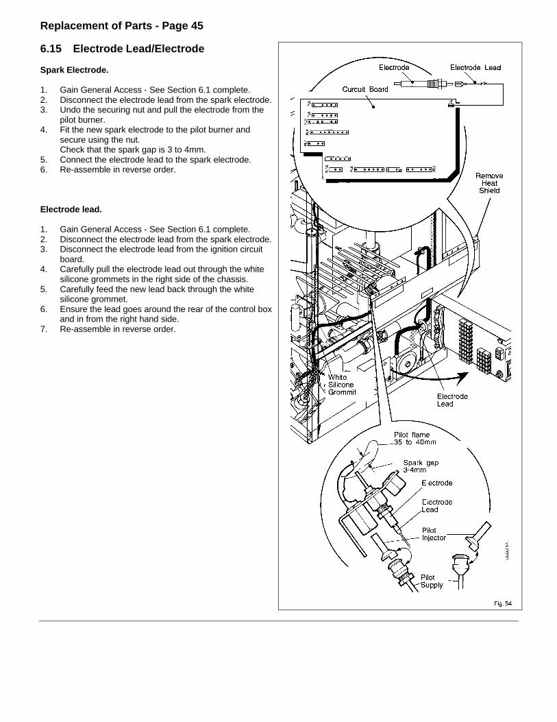
6.12 Potterton Internal Programmer (If Fitted) .........436.13 Test Switch.......................................................446.14 Overheat Cut-Off Device ..................................446.15 Spark Electrode/Electrode Lead.......................456.16 Main Burner......................................................46
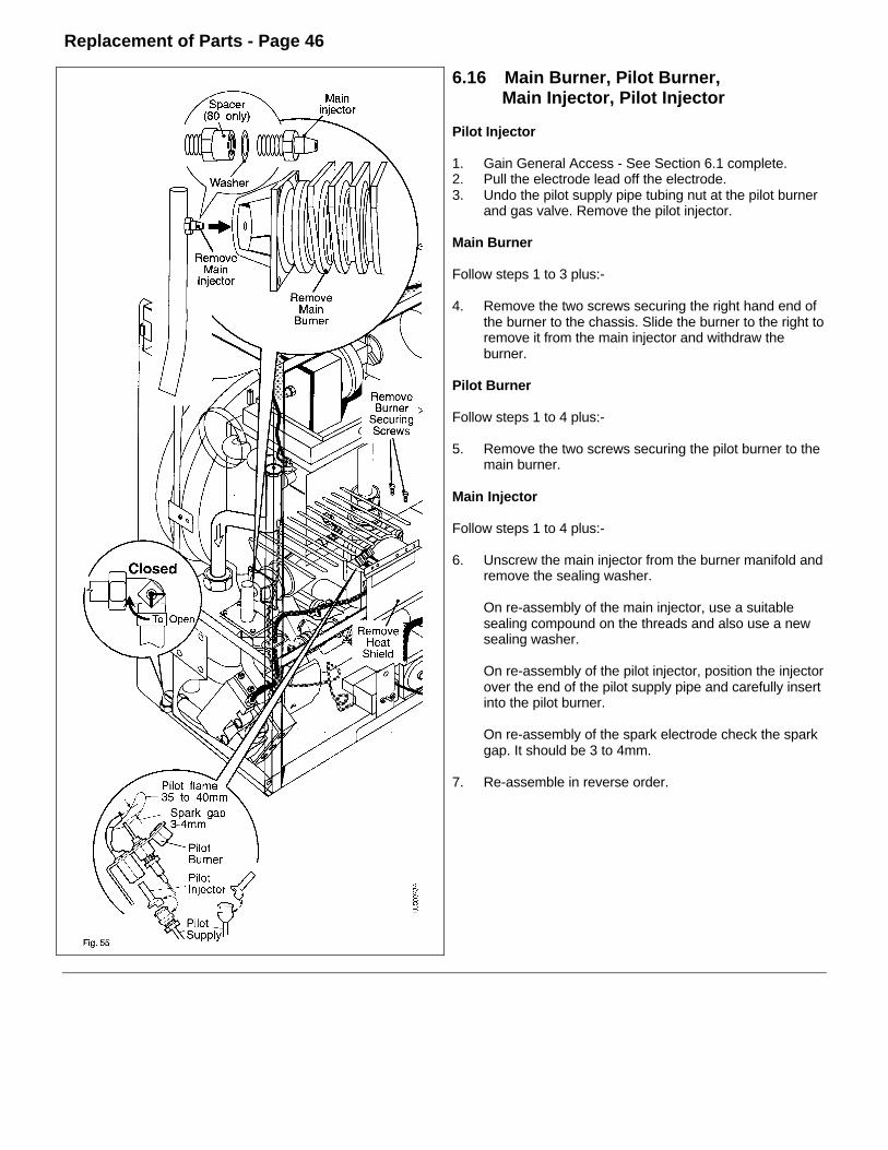
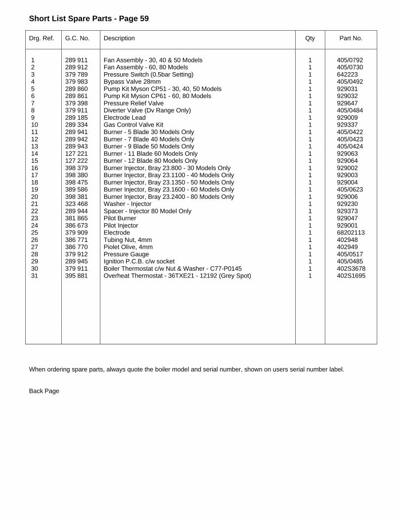
Pilot Burner.......................................................46Pilot Injector......................................................46Main Burner Injector.........................................46
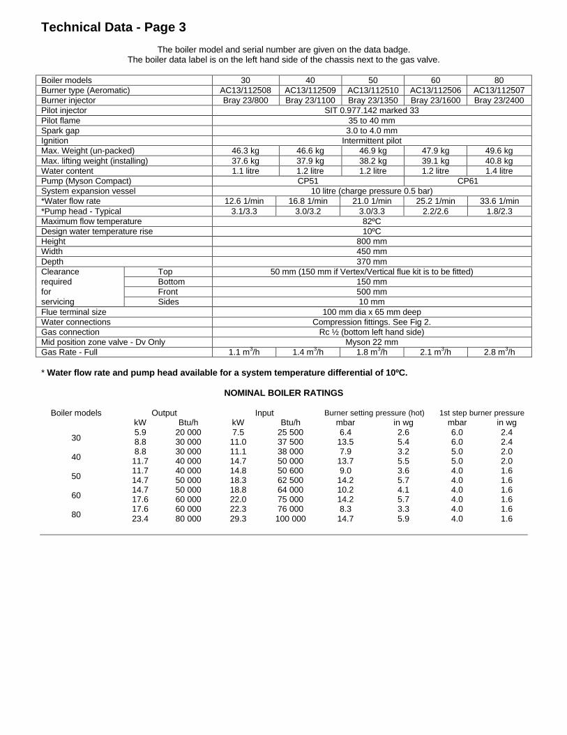
The boiler model and serial number are given on the data badge.The boiler data label is on the left hand side of the chassis next to the gas valve.
Boiler models 30 40 50 60 80Burner type (Aeromatic) AC13/112508 AC13/112509 AC13/112510 AC13/112506 AC13/112507Burner injector Bray 23/800 Bray 23/1100 Bray 23/1350 Bray 23/1600 Bray 23/2400Pilot injector SIT 0.977.142 marked 33Pilot flame 35 to 40 mmSpark gap 3.0 to 4.0 mmIgnition Intermittent pilotMax. Weight (un-packed) 46.3 kg 46.6 kg 46.9 kg 47.9 kg 49.6 kgMax. lifting weight (installing) 37.6 kg 37.9 kg 38.2 kg 39.1 kg 40.8 kgWater content 1.1 litre 1.2 litre 1.2 litre 1.2 litre 1.4 litrePump (Myson Compact) CP51 CP61System expansion vessel 10 litre (charge pressure 0.5 bar)*Water flow rate 12.6 1/min 16.8 1/min 21.0 1/min 25.2 1/min 33.6 1/min*Pump head - Typical 3.1/3.3 3.0/3.2 3.0/3.3 2.2/2.6 1.8/2.3Maximum flow temperature 82ºCDesign water temperature rise 10ºCHeight 800 mmWidth 450 mmDepth 370 mmClearance Top 50 mm (150 mm if Vertex/Vertical flue kit is to be fitted)required Bottom 150 mmfor Front 500 mmservicing Sides 10 mmFlue terminal size 100 mm dia x 65 mm deepWater connections Compression fittings. See Fig 2.Gas connection Rc ½ (bottom left hand side)Mid position zone valve - Dv Only Myson 22 mmGas Rate - Full 1.1 m3/h 1.4 m3/h 1.8 m3/h 2.1 m3/h 2.8 m3/h
* Water flow rate and pump head available for a system temperature differential of 10ºC.
NOMINAL BOILER RATINGS
Boiler models Output Input Burner setting pressure (hot) 1st step burner pressurekW Btu/h kW Btu/h mbar in wg mbar in wg
305.98.8
20 00030 000
7.511.0
25 50037 500
6.413.5
2.65.4
6.06.0
2.42.4
408.8
11.730 00040 000
11.114.7
38 00050 000
7.913.7
3.25.5
5.05.0
2.02.0
5011.714.7
40 00050 000
14.818.3
50 60062 500
9.014.2
3.65.7
4.04.0
1.61.6
6014.717.6
50 00060 000
18.822.0
64 00075 000
10.214.2
4.15.7
4.04.0
1.61.6
8017.623.4
60 00080 000
22.329.3
76 000100 000
8.314.7
3.35.9
4.04.0
1.61.6
Introduction - Page 4
Gas Safety (Installation & Use) Regulations 1994.
This appliance must be installed and serviced by acompetent person, in accordance with the above regulations.
In the UK 'Corgi' Registered Installers (including the regionsof British Gas Plc) undertake the work to a safe andsatisfactory standard.
Failure to install appliances correctly could lead toprosecution.
It is in your own interest, and that of safety, to ensure thatthe regulations are complied with.
The Ultra 2 boilers are range ratable and are factory set tothe maximum output.
The boilers are designed for use on sealed water systemsonly, with an indirect hot water cylinder.
THEY MUST NOT BE CONNECTED TO A DIRECTCYLINDER.
The boilers are for use on Natural Gas (G20) only.
Samples of the Potterton Ultra 2 gas system boilers havebeen examined by B.S.I., a United Kingdom Notified Body.The range is certified to comply with the essentialrequirements of the Gas Appliance Directive, the LowVoltage Directive and shows compliance with the ElectroMagnetic Compatibility Directive 89/336/EEC and aretherefore permitted to carry the CE Mark.
Delivery & Kits Available
The unit is delivered in two packages (1) the boiler withfittings and (2) the flue/terminal assembly.
A 1m Flue Extension Kit is available (the total flue lengthmust not exceed 3 m).
An Internal Programmer is also available that fits into thefacia.
A Vertex Flue Kt is available which allows the flue to exitvertically from the boiler (maximum length is 4.17 m).A Vertical Balanced Flue Kit is available which allows theflue to exit vertically from the boiler (maximum length3.25m).A Wall Spacing Kit is available which allows pipe-work to runbehind the boiler.A Fit From The Inside Flue Kit is available which allows theflue/terminal assembly to be fitted from inside the building.
1. Installation Requirements - Page 4
1.1 Health and Safety Information for theInstaller and Service Engineer
Under the Consumer Protection Act 1987 and Section 6 ofthe Health and Safety at Work Act 1974, we are required toprovide information on substances hazardous to health.
Small quantities of adhesives and sealants used in theproduct are cured and present no known hazards.
The following substances are also present.
Insulation and SealsMaterial - Ceramic Fibre. Alumino - Silicone Fibre.Description - Boards, Ropes, Gaskets.Known Hazards - Some people can suffer reddening and
itching of the skin. Fibre entry into the eye will causeforeign body irritation. Irritation to respiratory tract.
Precautions - People with a history of skin complaints maybe particularly susceptible to irritation. High dust levelsare only likely to arise following harsh abrasion. Ingeneral, normal handling and use will not presentdiscomfort, follow good hygiene practices, wash handsbefore consuming food, drinking or using the toilet.
First Aid - Medical attention must be sought following eyecontact or prolonged reddening of the skin.
Heat ExchangerMaterial - Copper with lead/tin coating.Description - Finned copper tube.Known Hazards - Inhalation or ingestion of lead dust or
fumes may cause headache and nausea.Precautions - Unused heat exchangers present minimal risk
to health other than normal hygiene practices woulddemand regarding washing before eating etc. Depositsfound on or below a heat exchanger that has been in usecould contain lead oxide. Avoid inhalation by using avacuum cleaner in conjunction with other cleaning toolswhen servicing the boiler.
1.2 Codes of Practice
The boiler must be installed in accordance with: The GasSafety (Installation and Use) Regulations 1994 and thecurrent issue of:-
The Building Regulations, Building Standards (Scotland)Regulations, Local Building Regulations, Model and localWater Undertaking Bye-laws, IEE Wiring Regulations andHealth & Safety Document No. 635 "The Electrician At WorkRegulations 1989".Detailed recommendations are stated in the following BritishStandards: BS6891:1988, BS6798:1987, BS5546:1990,BS5440:1:1990, BS5440:2:1989 and BS5449:1990.
Installation Requirements - Page 5
1.3 Gas Supply
The meter and supply pipes must be capable of delivering this quantity of gas in addition to the demand from any otherappliances in the house.
The complete installation must be tested for gas soundness and purged as described in BS6891.
1.4 Electricity Supply
230 / 240V ~ 50Hz via a fused double pole switch with a contact separation of at least 3 mm in both poles adjacent to theboiler. Power consumption is approximately 150W. There must be only one common isolator for the boiler and its controlsystem and it must provide complete electrical isolation.
Fuse the supply at 3 A. The minimum requirement for the power supply cable is that it should be a PVC sheathed cord atleast 0.75 mm² (24 x 0.2 mm) (code designation HO5 VV-F or HO5 VVH2-F) as specified in table 16 of BS6500:1984.
All wiring external to the boiler shall comply with the latest IEE Wiring Regulations, and any local regulations which apply.
WARNING: THIS APPLIANCE MUST BE EARTHED.
In the event of an electrical fault after installation of the boiler, preliminary electrical systems checks must be carried out i.e.Earth Continuity, Short Circuit, Polarity and Resistance to Earth.
1.5 Location of Boiler
The boiler is not suitable for external installation.
The boiler must be mounted on a flat wall which is sufficiently robust to take the weight of the boiler.
The boiler is suitable for installation to a combustible wall e.g. wood cladding, provided that the flue duct is not closer than 25mm to combustible material. A metal sleeve should be installed to surround the flue duct to provide a 25mm annular space.Further guidance is given in BS5440:1:1990, sub-clauses 3.3 and 4.2.5.
If the boiler is to be installed in a timber framed building it should be fitted in accordance with the British Gas publication-“Guide for Gas Installation in Timber Framed Housing” reference DM2. If in doubt advice must be sought from the localregion of British Gas or from Potterton Myson.
The boiler may be installed in any room, although particular attention is drawn to the requirements of the current IEE WiringRegulations and, in Scotland, the electrical provisions of the Building Standards applicable in Scotland with respect to theinstallation of the boiler in a room containing a bath or shower.
Where a room-sealed appliance is installed in a room containing a bath or shower, any electrical switch or appliance control,utilising mains electricity should be so situated that it cannot be touched by a person using the bath or shower.Where the installation of the boiler will be in an unusual position, special procedures may be necessary and BS6798 andBS5546 give detailed guidance on this aspect.
A cupboard or compartment used to enclose the boiler must be designed and constructed specifically for this purpose. Anexisting cupboard or compartment may be used provided that it is modified for the purpose. Details of essential features ofcupboard/compartment design including airing cupboard installations are given in BS6798 and BS5546 and should becomplied with.
The boiler requires only the clearances stated in the Technical Data, Page 3, after installation. If it is felt that extra space isrequired for installation any adjacent kitchen units or fitments may have to be removed.
The boiler must be installed so that the flue terminal is exposed to the external air. It is important that the position of theterminal allows the free passage of air across it at all times.
Installation Requirements - Page 6
Fig 1
Installation Requirements - Page 7
Fig 2
Installation Requirements - Page 8
1.6 Air Supply
The room in which the boiler is installed does not require a purpose provided air vent.If the boiler is installed in a cupboard or compartment, permanent air vents are required in the cupboard or compartment,one at high level and one at low level, either direct to the outside air or to a room. Both high level and low level air ventsmust communicate with the same room or must be on the same wall to outside air. Both the high level and low level ventmust each have a free area as stated below. The free area of each vent may be halved if the ventilation is provided directlyfrom outside.
If the boiler is installed in a cupboard or compartment with a door, allow at least 50 mm clearance between the front of theboiler and the door for air movement.
1.7 Horizontal Flue System
The flue/terminal assembly supplied with the boiler is 600 mm long.A 1 m flue extension is available, if required.Under no circumstances should the total flue length exceed 3 m. A 3 m length flue would comprise of the standard flue andthree 1m extension kits, one of which would be cut down to 400mm.
1.8 Water Connections
Isolation valves are supplied loose with the boiler. See Fig 2.A short safety valve discharge pipe is provided on the boiler. It must be possible to break the joint and the remainder of thedischarge pipe (not provided) should it ever be necessary to remove the boiler from its wall plate.Note: The flow and return connections at the base of the boiler have been temporarily sealed with plastic plugs.Remove ALL plugs before connecting the isolation valves.Use the pressure gauge connection at the water manifold as the drain point for the boiler.Fit one or more draining taps (BS2879) to enable the water system to be fully drained.A factory set by pass is built into the boiler and MUST NOT be adjusted.The pressure relief valve MUST NOT be used to drain the boiler.
1.9 Sealed System Requirements
1. The installation must comply with the requirements of BS6798 and BS5449. Maximum water temperature is 82°C ±3°C.
2. A safety valve set to operate at 3 bar and a pressure gauge covering the range 0 to 6 bar are incorporated within theboiler.
3. A 10 litre expansion vessel to BS4841 is fitted and pre-charged to 0.5 bar. The maximum water content is shown in thetable below.
4. Water lost from the system shall be replaced from a make-up vessel, and double check valve, mounted higher than thetop of the system or manually by a temporary hose connection, remove the temporary hose after use.See Fig 3.Note: Stop valves must comply with the requirements of BS1010:2.
5. The hot water cylinder shall either be the indirect coil type or a cylinder fitted with an immersion calorifier.6. The automatic air vent supplied with the boiler MUST be fitted in a tee on a horizontal section of pipe at the highest
point in the system.
Expansion Vessel.
The expansion vessel is charged to 0.5bar. The volume ofexpansion vessel varies with the overall system volume andthe cold fill pressure. The greater the cold fill pressure, thegreater the volume of the water stored in the vessel toreplace any slight water leaks. At the same time this willreduce the maximum available system volume. Theexpansion vessel volume is 10 litres. Subtract this from thefigures given in the chart opposite, to give the volume of anadditional vessel.
These instructions assume you have decided on the wherethe boiler will be located and the type of flue system to beused.
1. Carefully unpack the boiler.2. Do not discard any packaging until all the items are
accounted for.3. Check that the polythene bag contains the items shown
on the check list.
Note: Leave the transit plate secured to the boiler untilthe boiler is mounted on the wall.
4. Pull down the control cover flap to expose the facia.Pull off the thermostat knob. Remove the 2 screwssecuring the facia to the side panels and remove thefacia/control cover carefully unclipping the two neons asyou pull the facia away.
Note: Unplug programmer (if fitted) from back of thecontrol box
5. Pull the bottom of the white front case forward torelease the bottom ball studs, continue pulling until thetop studs release, then lift slightly and pull away fromthe boiler.
6. Remove the two white side panels - 2 screws eachside.
7. Remove the combustion chamber cover - 4 screws.8. Disconnect the flexible tube and fan motor wires from
the fan assembly.9. Remove the two screws securing the fan assembly to
the flue hood and carefully withdraw the fan.
Go to the applicable option/flue installation section
Wall Spacing Kit - Page 12.
Horizontal Rear Flue - Page 13.
Horizontal Side Flue - Page 15.
Flue Extension - Page 17.
Vertical Flue - Page 18.
Vertex Flue - Page 21.
Horizontal Fit from the Inside Flue - Page 24.
Installation - Page 11
2.2 Options Available for Ultra 2
UL
00
10
1B
Vertex Flue Kit Part No.B4287
Vertical Balanced Flue TerminalKit Part No. B4288
Standard Horizontal Flue Kit Part No. B4285
ExtensionPart No. B4286
OuterSealingPlate
Outer PlateScrews & Plugs
(4 off)
Flue LinerScrews & Plugs
(2 off)
OuterWallPlate
Rubber Gasket
FlueTerminal
Inner WallSeal
Wall Liner
Wall Plugs (2 off)
Self TappingScrews (6 off)
Extension Flue Tube
Vertex FlueTube
Gasket
Gasket
Terminal Securing Brackets & Screws
Adaptor
Adaptor
SpacingPlate
5 Screws (WallMounting Plate
To Spacing Plate)
AdaptorSecuringScrews(4 off)
SealingTape
AdaptorSecuringScrews(4 off)
TerminalCowl
SealingPlate
SealingPlate
Extension Air Tube Centralizing Spring
Fixing Bracket
Woodscrews (2 off)
Flue TubeSleeve
Wall Spacing Kit Part No.B4278
ProgrammerPart No. B4284
Fit From Inside Flue Kit Part No. B4263
FlueRetainingBrackets
Programmer Assembly
ProgrammerSecuringBracket
SecuringScrews(2 off)
WallLiningTube
OuterWallPlate
Fig. 7
Installation - Page 12
H,IK
G
D FJ
N
A
P
R
Q Q
SN
UL00110C
N
A
A
B,C B,C
C
EF
G GGG
K
L L
K
K
F F
UL0
00
53
C
Fig. 8
Dim. Terminal Position (Fanned Balanced Flue models) Min. Spacing
A Directly below an opening, air brick, window, etc. 300
B Below gutters, soil pipes or drain pipes 75 *
C Below eaves 200 *
D Below balconies or car port roofs 200
E From a vertical drain pipe or soil pipe 75
F From an internal or external corner 25
G Above ground, roof or balcony level 300 **
H From a surface facing the terminal 600
I From a terminal facing the terminal 1200
J From an opening in the car port (e.g. door, window) into dwelling 1200
K Vertically from a terminal on the same wall 1500
L Horizontally from a terminal on the same wall 300
N Above roof level (to base of terminal) 300
P From adjacent wall to flue 210
Q From internal corner to flue 230
R Below eaves or balcony 600
S From facing terminal 1200
*If the terminal is fitted within 850mm of a plastic or paintedgutter/pipe or 450mm of painted eaves, an aluminium shield ofat least 750mm in length should be fitted to the underside of thegutter/pipe or painted surface.
** If the terminal is fitted less than 2m above a balcony, aboveground or above a flat roof to which people have access, then asuitable terminal guard must be provided and fitted.
A type K1 (G.C. No. 393 552) protective guard is available from Tower Flue Components Ltd. at: Vale Rise, Tonbridge, Kent TN91TB, Tel: (01732) 351555. The guard must be securely fitted to the wall and centrally located over the flue terminal. Refer to themanufacturers instructions.
2.3 Fit the Optional Wall Spacing KitThe wall spacing kit allows the boiler to be spaced 40 mm fromthe wall, providing sufficient room for all pipework to be runbehind the boiler.
Kit ContentsItem QtySpacing Plate 1M6 x 12lg Screw 5
1. Decide upon the position of the boiler using the wall platesupplied with the boiler. Ensure that the wall plate is leveland mark the centre lines of the flue opening onto the wall.Using these lines as a guide mark the positions of the sixspacing plate fixing holes you will use (12 holes areprovided to avoid drilling into mortar). Drill and plug theseholes to accept 2½" lg. No.12 woodscrews.
2. If rear exit flue is to be used, cut the hole in the wall beforefitting the spacing plate.
3. Secure the spacing plate to the wall with six 2½" lg. No.12woodscrews (not supplied).Ensure that the spacing plate islevel.
4. Secure the wall plate, supplied with the boiler, to thespacing plate with the five screws supplied with this kit.
5. Continue to install the boiler as described in the relevantflue section.
IMPORTANTAs the boiler is now spaced off the wall by 40mm, alldimensions quoted in the flue sections for the position ofthe flue in relation to the wall must be increased by 40mm.
Installation - Page 13
2.4 Install the Boiler and Rear Flue
1. Having noted the clearances needed for installation(flue terminal & boiler), position the wall mounting plateagainst the wall (ensure it is level) and mark theposition of the flue hole and centre, plus a minimum offour of the mounting holes. Remove the wall mountingplate.
Important: Before drilling or cutting the wall ensure there areno water pipes, gas pipes or electric cables.
2. Drill and plug 4 holes (min.) for the wall mounting plateto accept 2½" long woodscrews (not supplied). Fromthe marked flue centre, cut a 127mm diameter holethrough the wall, if possible use a 127mm (5") core drill.
3. Measure the wall thickness and cut the wall liner to thesame length. Insert the wall liner into the wall, ensurethe seam is to the top and that the tabs are horizontal,(no screws are required as the wall liner will be held inplace by the wall mounting plate).
Make good the wall (if required).
4. Attach the wall mounting plate to the wall. Ensure it islevel.
5. Lift the boiler into position over the wall plate. The twoV shaped cut outs in the top mounting bracket locatebehind the two prongs on the wall plate.
6. Choose one of the bottom boiler fixing points, mark theposition then drill and plug to accept a 1" woodscrew(not supplied). See Fig.11.
7. Insert a woodscrew (not supplied) into the bottom fixinghole to secure the boiler to the wall.
Fig. 11
Installation - Page 14
UL
00
10
5B
FlueTerminal
RubberGasket
Slide the sealingring & clamping
plate over the airtube & secure tothe boiler chassis
with 4 screws
BoilerChassis
OuterWallPlate
Mark,drill,
plug &securewith 4screws
OuterSealingPlate
Fig 13
8. Remove the clamping plate & sealing ring from the rearboiler chassis flue hole, place to one side.
9. Measure the wall thickness from the edge of the outerwall to the flue hole in the boiler chassis. Add 15mm(9mm for 80 model)and mark this distance on the fluefrom the terminal flange. See Fig. 12.Put wedges in the end of the flue to stop the outer fluecompressing onto the inner.Cut squarely through both the inner and outer tubes.Remove all burrs.
10. Locate the outer wall plate and rubber gasket onto thedie cast flue terminal.See Fig.13.
11. From the outside, insert the flue through the wall linerand through the wall mounting plate.
12. Ensure that the outer wall plate is flush with the wall.13. Position the outer sealing plate, mark the four mounting
holes and remove.
Note: Cover the terminal before drilling to prevent debrisentering the terminal.
14. Drill and plug the holes to accept No. 8 x 1"woodscrews, remove the covering from the terminal, re-position the outer sealing plate and secure to the wall.
15. Slide the sealing ring and clamping plate over the flueand push up to the boiler chassis. Secure using the fourscrews previously removed. See Fig.13.
16. Ensure that the 'O' ring is in position on the fan outlet,then fit the flue tube sleeve, over the fan outlet andpush it fully home.
17. Place the fan assembly on top of the flue hood with theoutlet facing to the rear and reconnect the two fanmotor leads (polarity not important) and the air pressureswitch tube.
18. With the fan assembly resting on the flue hood push ittowards the rear of the boiler, locate the flue tubesleeve on the fan outlet into the inner tube of theflue/terminal assembly and push the fan assembly fullyhome until the base is located under the returns at therear of the flue hood.
19. Secure the front of the fan assembly to the flue hoodwith the two screws previously removed.
20. Remove the four screws securing the transit plate to thebottom of the boiler, discard the plate and screws.
21. Remove the screw and unhook the base plate - DONOT discard these items.
22. Proceed to Section 2.10.
Installation - Page 152.5 Install the Boiler and Side Flue1. Having noted the clearances needed for installation
(flue terminal & boiler), position the wall mounting plateagainst the wall (ensure it is level) and mark theposition of the flue hole and centre, plus a minimum offour of the mounting holes. Remove the wall mountingplate.
Important: Before drilling or cutting the wall ensure thereare no water pipes, gas pipes or electric cables.
2. Drill and plug 4 holes (min.) for the wall mounting plateto accept 2½" long woodscrews.
3. Attach the wall mounting plate. Ensure it is level.4. From the centre of the flue hole on the wall mounting
plate draw a level horizontal line along the wall to thecorner, continue the horizontal line along the side walland mark the position of the flue hole as shown. SeeFig.15.
5. From the marked flue centre, cut a 127mm diameterhole through the wall, if possible use a 127mm (5")core drill.
6 .Measure the wall thickness and cut the wall liner to thesame length. See Fig.16 Bend back the wall liner lugs(90°).From the inside insert the wall liner into the wall,ensure the seam is to the top and that the tabs arehorizontal, mark, drill, plug & screw the wall liner intoposition.Make good the wall (if required).
7. Remove the four screws and clamping plate & sealingring from the rear of the boiler chassis. Remove theblanking plate from the side of the chassis & fit to therear flue opening.Lift the boiler into position over the wall plate. The twoV shaped cut outs in the top mounting bracket locatebehind the two prongs on the wall plate.Note: If the measurement taken in paragraph 8 belowis less than 600mm carry on with the installation, ifgreater than 600mm go to Section 2.5.
8. Measure the wall thickness from the edge of the outerwall to the flue hole in the boiler chassis. Add 15mmand mark this distance on the flue from the terminalflange.
9. Put wedges in the end of the flue to stop the outer fluecompressing onto the inner. Cut squarely through boththe inner and outer tubes. Remove all burrs.
10. Choose on of the bottom boiler fixing points. Mark theposition then drill and plug to accept a 1" woodscrew(not supplied). Insert a screw into the bottom fixing hole& secure the boiler.
UL00045B
36mmSide
Clearance
Spirit Level
Markfor
horizontal
36mm SideClearance
515mmBottom
Clearance
Mark Off TheFlue Centre.
Use A 127mm(5") Core Drill
To Cut Flue Hole.Make Sure YouDO NOT Cut
Through CablesOr Pipes
These are minimumclearances for side flues
70mm TopClearance
227mm(267mm withwall spacer)
Mark, drill & plug4 holes ready to
take the wallmounting plate
securing screws,(if a you hit a brick
joint use otherholes provided).
Fig 15
Fig 17
Installation - Page 16
UL0
01
08
B
RubberGasket
Inner WallSeal
Take the ClampingPlate & SealingRing of the rear
flue outlet & fit theside blanking plateover the rear flue
hole. Slide thegasket & plate
over the air tube& secure to the
boiler chassiswith 4 screws
Fitted side blanking plateto rear flue outlet
OuterWallPlate
Mark,drill,
plug &securewith 4screws
OuterSealing Plate
Fit thewhiteside
panelbeforefitting
the sideflue
FlueTerminal
Fig. 19
UL00
022
A
FlueHood
Fan & DiverterAssembly
Right handFlue Outlet
Left handFlue Outlet
Connect flue tube sleeve to fan & slidethe whole assembly into position
Connect flue tube sleeveto fan & slide the whole
assembly into position
FlueSampling
Point
Fan
Fig 20
11. Remove the cover plate from the white case side andattach the panel to the boiler.
12. Locate the outer wall plate and rubber gasket onto thedie cast flue terminal.
13. From the outside, insert the flue through the hole in thewall.From the inside slide the inner wall seal over the flueassembly.
14. Ensure that the terminal is flush with the outside walland that the rubber gasket is in the wall liner (sealing offthe wall liner from the outside).
15. Position the outer sealing plate, over the flue terminal,mark the four mounting holes on the outside wall andremove.
Note: Cover the terminal before drilling to prevent debrisentering the terminal.
16. Drill and plug the holes to accept No. 8 x 1"woodscrews, remove the covering from the terminal, re-position the outer sealing plate and secure to the wall.
17. Slide the sealing ring and clamping plate over the flueand push up to the boiler chassis. Secure using the fourscrews previously removed. See Fig 19.
18. Ensure that the 'O' ring is in position on the fan outlet,then fit the flue tube sleeve, over the fan outlet andpush it fully home.
19. Place the fan assembly on top of the flue hood with theoutlet facing to the side and connect the flue together.Reconnect the two fan motor leads (polarity notimportant) and the air pressure switch tube.
20. With the fan assembly clipped on at the back of the fluehood.Secure the front of the fan assembly to the fluehood with the two screws previously removed.
21. Check that the flue tube sleeve is fully connected to thefan assembly & flue.
22. Remove the four screws securing the transit plate to thebottom of the boiler, discard the plate and screws.
23. Remove the screw and unhook the base plate - DONOT discard these items.
24. Proceed to Section 2.10.
Installation - Page 17
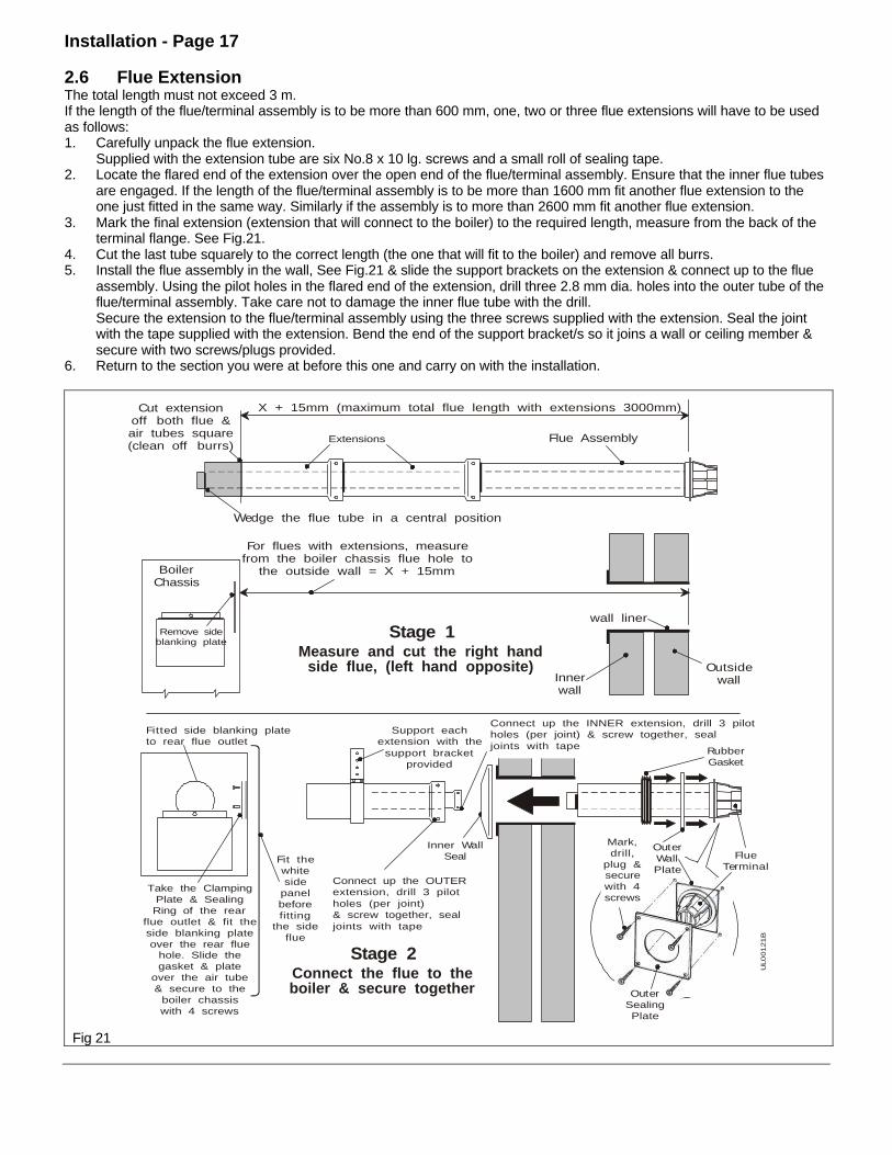
2.6 Flue ExtensionThe total length must not exceed 3 m.If the length of the flue/terminal assembly is to be more than 600 mm, one, two or three flue extensions will have to be usedas follows:1. Carefully unpack the flue extension.
Supplied with the extension tube are six No.8 x 10 lg. screws and a small roll of sealing tape.2. Locate the flared end of the extension over the open end of the flue/terminal assembly. Ensure that the inner flue tubes
are engaged. If the length of the flue/terminal assembly is to be more than 1600 mm fit another flue extension to theone just fitted in the same way. Similarly if the assembly is to more than 2600 mm fit another flue extension.
3. Mark the final extension (extension that will connect to the boiler) to the required length, measure from the back of theterminal flange. See Fig.21.
4. Cut the last tube squarely to the correct length (the one that will fit to the boiler) and remove all burrs.5. Install the flue assembly in the wall, See Fig.21 & slide the support brackets on the extension & connect up to the flue
assembly. Using the pilot holes in the flared end of the extension, drill three 2.8 mm dia. holes into the outer tube of theflue/terminal assembly. Take care not to damage the inner flue tube with the drill.Secure the extension to the flue/terminal assembly using the three screws supplied with the extension. Seal the jointwith the tape supplied with the extension. Bend the end of the support bracket/s so it joins a wall or ceiling member &secure with two screws/plugs provided.
6. Return to the section you were at before this one and carry on with the installation.
UL0
0121B
For flues with extensions, measurefrom the boiler chassis flue hole to
the outside wall = X + 15mm
Outsidewall
Wedge the flue tube in a central position
Cut extensionoff both flue &air tubes square(clean off burrs)
Connect up the OUTER extension, drill 3 pilotholes (per joint)& screw together, sealjoints with tape
Support eachextension with the
support bracketprovided
Extensions Flue Assembly
X + 15mm (maximum total flue length with extensions 3000mm)
wall liner
Innerwall
Remove sideblanking plate
BoilerChassis
Measure and cut the right handside flue, (left hand opposite)
Connect the flue to theboiler & secure together
Stage 1
Stage 2
RubberGasket
Inner WallSeal
Take the ClampingPlate & SealingRing of the rear
flue outlet & fit theside blanking plateover the rear flue
hole. Slide thegasket & plate
over the air tube& secure to the
boiler chassiswith 4 screws
Fitted side blanking plateto rear flue outlet
OuterWallPlate
Mark,drill,
plug &securewith 4screws
OuterSealingPlate
Fit thewhiteside
panelbeforefitting
the sideflue
FlueTerminal
Connect up the INNER extension, drill 3 pilotholes (per joint) & screw together, sealjoints with tape
Fig 21
Installation - Page 12
2.7 Fit the Optional Vertical Balanced Flue
This Vertical Balanced Flue kit is only for use with the Ultra 2 Boiler and allows the flue to run vertically from the boiler,terminating above either a flat or pitched roof.
The kit must be used with at least ONE, and up to THREE 1 metre flue extension kits, in conjunction with the horizontalstandard flue kit. The minimum flue length is 1.2 metres and the maximum permissible flue length is 3.25 metres.
To render the installation weatherproof, a storm collar and an adjustable flashing are recommended. The size of thesecomponents should be to suit a 3 in. Twin Wall B vent flue system from:
A Directly below an openablewindow or other openinge.g. air brick
B Above roof level C From adjacent wall D From internal corner E Below eaves or balcony F From facing terminal
300 mm300 mm210 mm230 mm600 mm1200 mm
Kit Contents
Description Qty
Flue Terminal Cowl 1Vertical flue adaptor ring 1Sealing plate 1Gasket 1M4 x 16 Ig. hex. hd. screw 4Support brackets 3No.8 x 10 Ig. pozi hd. screw 12Ceiling template 1
Installation - Page 19
1. Carefully unpack the kit, do not discard the packaging until all the items are found. The sealing ring and clamping platesupplied with the boiler are not required when the Vertical Balanced Flue kit is used and should be discarded.
2. Having noted the clearances needed for installation (flue terminal & boiler), position the wall plate against the wall(ensure it is level) and mark the position of the flue hole and a minimum of four of the mounting holes. Remove the wallplate.Important: Before cutting through the ceiling ensure there are no water pipes, gas pipes or electric cables.
3. Drill and plug the wall to accept 2½" long woodscrews (not supplied).4. Attach the wall plate to the wall. Ensure it is level.
A line is marked at the top of the mounting plate which indicates the centre line of the Vertical Balanced Flue. Continuethis line vertically upwards to the ceiling. This line must not be closer than 75 mm to any ceiling joist, this will ensurethere is adequate clearance for fitting and spacing from combustible material (BS5440:1:1990). Check that the flue willterminate in accordance with the relevant recommendations given in BS5440:1.
5. Tape the ceiling template to the ceiling with the appropriate edge (indicated on the template) against the wall, and theline drawn vertically downwards, indicating the flue centre line, lined up with the template centre line.
6. Mark the position of the four sealing plate fixing holes and the 134 mm diameter hole on the ceiling. Remove thetemplate and drill and plug the four fixing holes to accept 1 in long No.8 woodscrews (not supplied). Cut the 134 mmdiameter hole in the ceiling as neatly as possible.
7. Lift the boiler into position over the wall plate. The two V shaped cut outs in the top mounting bracket locate behind thetwo prongs on the wall plate.
8. Choose on of the bottom fixing points, mark the position then drill and plug to accept a 1" woodscrew (not supplied).9. Measure from the top of the boiler to the proposed terminal position to obtain dimension ‘A’ - See Fig. 22. The bottom
of the flue terminal cowl MUST be at least 300 mm above the inter-section of the roof and flue, this will ensureadequate clearances for the safe operation of the boiler. From dimension ‘A’, determine the number of flue extensionsrequired, if any, and cut the flue tubes to the required length. Ensure that the tubes are cut square. Remove all burrs.
10. Fit the flue terminal cowl over the end of the flueterminal die-casting and secure the three supportbrackets to the bottom of the cowl. Position the cowlsuch that it’s bottom edge extends 30 mm past the rearedge of the terminal die-casting and that the separatorplate locates over the end of the terminal die-casting.Drill through the six holes in the support brackets, usinga 2.8mm diameter drill, taking care not to damage theinner flue tube with the drill. To assist with theinstallation it is advisable to remove the flue terminalcowl assembly.
11. If a flue extension is to be used, secure and seal to theflue system as follows:- Separate the inner and outerflue extensions, locate the flared end of the innerextension over the open end of the flue systemsupplied with the boiler. Drill through the pilot holes, inthe flared end of the extension after the extension hasbeen fitted - use a 2.8 mm diameter drill. Note: Prior tosecuring the extension(s) to the flue, the storm collarand adjustable flashing must be loosely assembled tothe upper flue. Secure the extension to the flue usingthe three screws supplied with the flue extension. Sealthe joint with the tape supplied with the flue extension.Repeat the procedure for the outer flue extension - takecare not to damage the inner flue extension whendrilling through the outer.
12. Locate the adaptor ring, supplied with the kit, onto theboiler connection of the flue system and drill throughthe three holes using a 2.8 mm diameter drill, takingcare not to damage the inner flue tube with the drill.
UL00
10
9B
36mmSide
Clearance
SpiritLevel
36mm SideClearance
515mmBottom
Clearance
Mark the centre line up to the ceiling& with the sealing template markoff the flue centre. Cut a 134mm diameter hole. Make sure you DO NOTcut through roofmembers,cables Or Pipes
These are minimum clearancesfor vertical/vertex flue
170mm
SealingTemplate
Mark, drill & plug4 holes ready totake the wallmounting plate securingscrews, (if a you hit abrick joint use otherholes provided).
Fig. 23
Installation - Page 20
FlueTerminal
Drill 3 pilot holesin flue tube(2.8mm dia.)
& screw together.
Slide the air tubeover flue tube &
secure in positionusing the
same method,as the
inner flue.
Extension(flue tube)
Extension(air tube)
UL00119B
Wedge theflue tube
in acentralposition
Extension
Seal this jointwith tape supplied
Cut extensionoff both flue &air tubes square(clean off burrs)
FlueTerminalPilot holes
(3 off)Stage 1
Stage 2
Drill 3 holesthrough
2.8mm dia.& secureflue with
No. 8 x 10Lgscrews
Vertical flueadaptor
Gasket
Unscrew 3fixing screws
& rotatefan motor
Inner tubeof flue
M4 x 16Lg Screws (4 off)
NOTE:The fluetubesMUSTNOTprotrudepast thisface
Flue tubesleeve onfan outlet
Support bracketshould be atthe bottom
UL00115B
Fig. 24
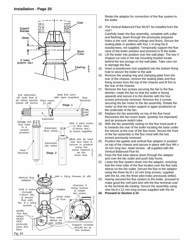
Retain the adaptor for connection of the flue system tothe boiler.
13. The Vertical Balanced Flue MUST be installed from theroof !Carefully lower the flue assembly, complete with collarand flashing, down through the previously preparedholes in the roof, internal ceilings and floors. Secure thesealing plate in position with four 1 in long No.8woodscrews, not supplied. Temporarily support the flueclear of the boiler position and proceed to fit the boiler.
14. Lift the boiler into position over the wall plate. The two Vshaped cut outs in the top mounting bracket locatebehind the two prongs on the wall plate. Take care notto damage the flue.
15. Insert a woodscrew (not supplied) into the bottom fixinghole to secure the boiler to the wall.
16. Remove the sealing ring and clamping plate from therear of the chassis, remove the sealing plate and fourfixing screws from the top of the chassis and fit this tothe rear of the chassis.
17. Remove the four screws securing the fan to the fluediverter, rotate the fan so that the outlet is facingupwards and secure it to the diverter with the fourscrews previously removed. Remove the 3 screwssecuring the fan motor to the fan assembly. Rotate themotor so that the motor support is again positioned atthe underside of the fan.
18. Replace the fan assembly on top of the flue hood.Reconnect the fan motor leads (polarity not important)and air pressure switch tube.
19. With the fan assembly resting on the flue hood push itto towards the rear of the boiler locating the base underthe returns at the rear of the flue hood. Secure the frontof the fan assembly to the flue hood with the twoscrews previously removed.
20. Position the gasket and vertical flue adaptor in positionon top of the chassis and secure in place with four M4 x16 mm long hex. head screws - all supplied with theVertical Balanced Flue kit.
21. Pass the flue tube sleeve down through the adaptorand over the fan outlet and push fully home.
22. Lower the flue system down into the adaptor, ensuringthat the inner tube of the flue locates over the flue tubesleeve on the fan outlet. Secure the flue to the adaptorusing the three No.8 x 10 mm long screws, suppliedwith the kit, into the three pilot holes previously drilled.
23. Having secured the flue system to the boiler, proceed tomake good the roof joint and refit the flue terminal cowlto the terminal die-casting. Secure the assembly usingnine No.8 x 12 mm long screws supplied with the kit.
24. Proceed to Section 2.10
Installation - Page 21
2.8 Fit the Optional Vertex Flue
This Vertex Flue kit is only for use with the Ultra 2 Boiler and allows the flue to be run vertically from the boiler. The kit maybe used as supplied or with one, two or three flue extension kits.
It is important that the roof space is ventilated direct to theoutside with a permanent vent. The minimum effective areaof the vent is given in the table opposite.
The table opposite gives the maximum lengths of thesecondary flue which may be connected to the Vertex Flue.
Note: The minimum length of the secondary flue is 0.5 m.
Boiler models Minimum air vent area
3040506080
198 cm2
265 cm2
330 cm2
428 cm2
527 cm2
Boiler models Max. secondary flue length at Min. boiler input
Max. secondary flue length at Max. boiler input
3040506080
2m 5m 5.5m 8m 10m
5m 5.5m 6m 10m 12m
Carefully unpack the kit, do not discard the packaging until all the items are found.
1. Carefully unpack the kit, do not discard the packaging until all the items are found. The sealing ring and clamping platesupplied with the boiler are not required when the Vertex Flue kit is used and should be discarded.
2. Having noted the clearances needed for installation (flue terminal & boiler), position the wall plate against the wall(ensure it is level) and mark the position of the flue hole and a minimum of four of the mounting holes. Remove the wallplate.Important: Before cutting through the ceiling ensure there are no water pipes, gas pipes or electric cables.
3. Drill and plug the wall to accept 2½" long woodscrews (not supplied).4. Attach the wall plate to the wall. Ensure it is level.
A line is marked at the top of the mounting plate which indicates the centre line of the Vertex Flue. Continue this linevertically upwards to the ceiling. This line must not be closer than 75 mm to any ceiling joist, this will ensure there isadequate clearance for fitting and spacing from combustible material (BS5440:1:1990, sub-clause 3.3 and 4.25). Checkthat the flue will terminate in accordance with the relevant recommendations given in BS5440:1. The flue must be fittedwith a terminal of a type which has been tested and found satisfactory by British Gas.
5. Tape the ceiling template to the ceiling with the appropriate edge (indicated on the template) against the wall, and theline drawn vertically downwards, indicating the flue centre line, lined up with the template centre line.
6. Mark the position of the four sealing plate fixing holes and the 134 mm diameter hole on the ceiling. Remove thetemplate and drill and plug the four fixing holes to accept 1 in long No.8 woodscrews (not supplied). Cut the 134 mmdiameter hole in the ceiling as neatly as possible.
7. The Vertex Flue supplied is 1170 mm long. Up to three flue extensions may be used, which will give a vertex flue lengthfrom 1170 to 4170 mm. The top of the air inlet mesh on the flue must be at least 400 mm above the roof joists, this willensure adequate clearance above any insulation materials.
8. If the distance from the top raised edge of the wall mounting plate to the top of the roof joists is more than 750 mm atleast one flue extension must be used with the Vertex Flue.
9. Fit the sealing plate over the flue (before any flue extensions are fitted).
Installation - Page 22
UL00109B
36mmSide
Clearance
SpiritLevel
36mm SideClearance
515mmBottom
Clearance
Mark the centre line up to the ceiling& with the sealing template markoff the flue centre. Cut a 134mm diameter hole. Make sure you DO NOTcut through roofmembers,cables Or Pipes
These are minimum clearancesfor vertical/vertex flue
170mm
SealingTemplate
Mark, drill & plug4 holes ready totake the wallmounting plate securingscrews, (if a you hit abrick joint use otherholes provided).
Fig. 25
10. If a flue extension is to be used, secure and seal this tothe bottom half of the Vertex Flue as follows:-Locate the flared end of the extension over the openend of the Vertex Flue. Ensure that the inner flue tubesare engaged.Rotate the tube until the three fixing holes line up, thensecure the tubes together using the three screwssupplied with the flue extension. Seal the joint with thetape supplied with the flue extension.If another one or two extensions are to be fitted, you willhave to drill through the pilot holes, in the flared end ofthe extension after the extension has been fitted - use a2.8 mm diameter drill, taking care not to damage theinner flue tube with the drill. Secure the extension usingthe three screws supplied with the flue extension. Sealthe joint with the tape supplied with the flue extension.
11. Pass the Vertex Flue assembly (mesh first) up throughthe hole into the roof space. Secure the sealing plate inposition with four 1 in long No.8 woodscrews, notsupplied. Temporarily support the flue.
12. Remove the sealing ring and clamping plate from therear of the chassis, remove the sealing plate and fourfixing screws from the top of the chassis and fit this tothe rear of the chassis.
13. Lift the boiler into position over the wall plate. The two Vshaped cut outs in the top mounting bracket locatebehind the two prongs on the wall plate. Take care notto damage the flue.
14. Insert a woodscrew (not supplied) into the bottom fixinghole to secure the boiler to the wall.
15. Remove the four screws securing the fan to the fluediverter, rotate the fan so that the outlet is facingupwards and secure it to the diverter with the fourscrews previously removed. Remove the 3 screwssecuring the fan motor to the fan assembly. Rotate themotor so that the motor support is again positioned atthe underside of the fan.
16. Replace the fan assembly on top of the flue hood.Reconnect the fan motor leads (polarity not important)and air pressure switch tube.
17. With the fan assembly resting on the fluehood push it to towards the rear of the boiler locating the base under thereturns at the rear of the flue hood. Secure the front of the fan assembly to the flue hood with the two screwspreviously removed.
18. Position the gasket and vertical flue adaptor in position on top of the chassis and secure in place with four M4 x 16 mmlong hex. head screws - all supplied with the kit.
19. Pass the flue tube sleeve down through the adaptor and over the fan outlet and push fully home.20. Lower the flue system down into the adaptor, ensuring that the inner tube of the flue locates over the flue tube sleeve
on the fan outlet. Secure the flue to the adaptor using the three No.8 x 10 mm long screws, supplied with the kit, intothe three pilot holes previously drilled.
21. Connect the secondary flue system.
Installation - Page 23
Connect The SECONDARY FLUE ToThe VERTEX FLUE
1. Always use compatible flue pipes, sockets, connectors,etc. for the complete flue system. Do not mixcomponents from different manufacturers.
The secondary flue must comply with BS5440:1 inrespect to routing, supporting, weather proofing, fireprecautions and must be connected to a suitable ridgeor roof terminal.
The flue outlet size is suitable for connection to pipeconforming to BS567 or BS715 with a suitable adaptor.
2. Suitable flue systems are available from:-(a) Rite Vent
Armstrong Industrial EstateWashingtonTyne and WearNE37 1LHTel: 0191 4161150
Using their 4'' Twin Wall B Vent flue system with astandard boiler connector, Part No. 145/04.
Using their 4'' Twin Wall IL Gas Vent flue system withspecial draught hood connector, Part No. 55504.
3. Three No.10 x 25 mm long screws are supplied with thekit to centralise the connector into the Vertex Fluesocket. This connector must be adequately sealed tothe Vertex Flue socket.
4. Complete the boiler installation as described in theboiler Installation instructions.
5. Instruct the User not to store anything in the roof spaceadjacent to the openings in the Vertex Flue pipe, nor toblock any purpose designed ventilation openings in theroof space.
Length of Vertex Flue (dimension A)
No flue extensionOne flue extensionTwo flue extensionsThree flue extensions
1170mm2170mm3170mm4170mm
Drill 3 holesthrough
2.8mm dia.& secureflue with
No. 8 x 10Lgscrews
Vertical flueadaptor
Gasket
Unscrew 3fixing screws
& rotatefan motor
Inner tubeof flue
M4 x 16Lg Screws (4 off)
NOTE:The fluetubesMUSTNOTprotrudepast thisface
Flue tubesleeve onfan outlet
Support bracketshould be atthe bottom
UL00115B
Fig. 26
Installation - Page 24
2.9 Fit the Optional Fit From The Inside Flue KitThe Fit From the Inside Flue Kit allows the flue/terminal assembly to be fitted entirely from inside the building and is suitablefor rear or side exit flue. The kit is only suitable for walls 100 - 375 mm thick and requires a 152 mm diameter hole to be cutthrough the wall.
Fig. 27
Description QtyOuter wall plate assembly 1Wall lining tube 1Flue retaining bracket 2Carefully unpack the kit, do not discard the packaging untilall the items are found.
To Fit The FIT FROM THE INSIDE FLUE KIT WithREAR Exit Flue
The rubber seal, inner plate, wall liner and outer wall platesupplied with the horizontal flue terminal are not requiredwith this kit.
1. Having noted the clearances needed for installation(flue terminal & boiler), position the wall plate againstthe wall (ensure it is level) and mark the position of theflue hole and a minimum of four of the mounting holes.Remove the wall plate.
Important: Before cutting through the wall ensure there areno water pipes, gas pipes or electric cables.2. Cut a 152mm diameter hole through the wall.3. Measure the wall thickness and cut the liner supplied
with this kit to the finished wall thickness LESS 2mm.Cut the end without the hooks and ensure the cut issquare. Insert the wall liner into the wall, ensure theseam is to the top and that the tabs are vertical, (noscrews are required as the wall liner will be held inplace by the wall mounting plate).Make good the wall (if required).
4. The outer wall plate is made so that when it is opened itis not flat. Do NOT try to bend it flat. Tie a suitablelength of string to one of the wall plate chains tosupport it if it is inadvertently dropped outside whenfitted. With the other end of the string secure, fold thewall plate, pass it through the wall lining tube andunfold outside. With the springs in line with the hookson the wall lining tube, carefully pull back on the chainsensuring that the four returns are located inside thelining tube. When the springs are well in tension, hookthe chains over the retaining hooks. Remove the stringpreviously tied to the chain.
5. To measure the flue length take the wall thickness &add 113mm, from the flue terminal flange measure &mark the flue. See Fig.27. Add a further 40mm if thewall spacing plate is fitted.Put wedges in the end of the flue to stop the outer fluecompressing onto the inner. Cut squarely through boththe inner and outer tubes. Remove all burrs.
Installation - Page 25
Fit the flue terminal in the wall liner.6. Attach the wall plate to the wall. Ensure it is level. Slide
the flue assembly back into the room, so the flueterminal disengages from the outer wall plate. The flueassembly will then be angled downward ready toaccept the boiler chassis.
7. Remove the clamping plate & sealing ring from theboiler chassis.Remove the flue hood. See Fig. 38Lift the boiler into position guiding the flue assemblythrough the rear flue outlet & hook the boiler onto thewall plate using the two V shaped cut outs in the topmounting bracket. See Fig.28.
8. Choose on of the bottom boiler fixing points. Mark theposition then drill and plug to accept a 1" woodscrew(not supplied). Insert a screw into the bottom fixing hole& secure the boiler.
9. Secure the flue sealing ring in position with theclamping plate using two screws.
10. Fit the two flue retaining brackets, supplied with this kit,to the remaining two holes in the flue sealing ringclamping plate using the remaining two screws.Carefully bend the brackets over the edge of the outerflue tube to retain it in position (to stop the flue beingpushed into the boiler). Refit the flue hood.
11. Insert a woodscrew (not supplied) into the bottom fixinghole to secure the boiler to the wall.
12. Ensure that the 'O' ring is in position on the fan outlet,then fit the flue tube sleeve over the fan outlet andpush it fully home.
13. Place the fan assembly on top of the flue hood with theoutlet facing to the rear and reconnect the two fanmotor leads (polarity not important) and the airpressure switch tube.
14. With the fan assembly resting on the flue hood push ittowards the rear of the boiler, locate the flue tubesleeve on the fan outlet into the inner tube of theflue/terminal assembly and push the fan assembly fullyhome until the base is located under the returns at therear of the flue hood.
15. Secure the front of the fan assembly to the flue hoodwith the two screws previously removed.
16. Remove the four screws securing the transit plate tothe bottom of the boiler, discard the plate and screws.
17. Remove the screw and unhook the base plate - DONOT discard these items.
18. Proceed to Section 2.10.
Installation - Page 26
To Fit The FIT FROM THE INSIDE FLUE KITWith SIDE Exit FlueWith side exit flue a minimum of 25 mm clearance isrequired on the opposite side to the flue for installation.The rubber seal, inner plate, wall liner and outer wall platesupplied with the horizontal flue terminal are not requiredwith this kit.
1. Having noted the clearances needed for installation(flue terminal & boiler), position the wall plate againstthe wall (ensure it is level) and mark the position of fourof the mounting holes. Remove the wall plate.Important: Before drilling or cutting the wall ensurethere are no water pipes, gas pipes or electric cables.
2. Drill and plug the mounting holes to accept 2½" longwoodscrews (not supplied).
3. Attach the wall plate to the wall. Ensure it is level.4. From the centre of the flue hole on the wall plate draw a
level horizontal line along the wall to the corner,continue the line along the side wall and mark theposition of the flue hole as shown.
5. Cut a 152mm diameter hole through the wall.6. Measure the wall thickness and cut the liner supplied
with this kit to the finished wall thickness LESS 2mm.Cut the end without the hooks and ensure the cut issquare. Insert the wall liner into the wall, ensure theseam is to the top and that the tabs are horizontal.
7. The outer wall plate is made so that when it is opened itis not flat. Do NOT try to bend it flat. Tie a suitablelength of string to one of the wall plate chains tosupport it if it is inadvertently dropped outside whenfitted. With the other end of the string secure, fold thewall plate, pass it through the wall lining tube andunfold outside. With the springs in line with the hookson the wall lining tube, carefully pull back on the chainsensuring that the four returns are located inside thelining tube. When the springs are well in tension, hookthe chains over the retaining hooks. Remove the stringpreviously tied to the chain.
8. Lift the boiler into position over the wall plate. The twoV shaped cut outs in the top mounting bracket locatebehind the two prongs on the wall plate.Note: If the measurement taken in 9 below is less than600mm carry on with the installation, if greater than600mm go toSection 2.5.
9. Measure the wall thickness from the edge of the outerwall to the flue hole in the boiler chassis. Add 15mmand mark this distance on the flue from the terminalflange.
Installation - Page 27
Put wedges in the end of the flue to stop the outer fluecompressing onto the inner. Cut squarely through boththe inner and outer tubes. Remove all burrs.
10. Mark one of the boiler fixing points, then drill and plugto accept a 1" woodscrew (not supplied).
11. Remove the clamping plate & sealing ring from the rearflue outlet & place to one side. Remove the blankingplate from the side of the chassis & fit to the rear flueoutlet. Fit the flue terminal in the wall liner. For themoment the flue assembly is not engaged in the outerwall plate, it will be angled downward ready to acceptthe boiler chassis. Slide the inner wall seal over the flueassembly.
12. Remove the cover plate from the white case side. Fitwhite side panel to boiler.
13. Guide the flue assembly through the side flue outlet &hook the boiler onto the wall mounting plate, using thetwo 'V' shaped cut outs in the top mounting bracket.See Fig.32
14. Fit the flue terminal into the outer wall plate. Secure theflue sealing ring in position with the clamping plateusing two screws.Fit the two flue retaining brackets, supplied with this kit,to the remaining two holes in the flue sealing ringclamping plate using the remaining two screws.Carefully bend the brackets over the edge of the outerflue tube to retain it in position (to stop the flue beingpushed into the boiler).
15. Insert a woodscrew (not supplied) into the bottom fixinghole to secure the boiler to the wall . Slide the innerwall seal up to the wall so it covers over the wall liner.
16. Ensure that the 'O' ring is in position on the fan outlet,then fit the flue tube sleeve over the fan outlet andpush it fully home.
17. Place the fan assembly on top of the flue hood with theoutlet facing to the side and reconnect the two fanmotor leads (polarity not important) and the airpressure switch tube.
18. With the fan assembly resting on the flue hood push ittowards the rear of the boiler, slide sideways andlocate the flue tube sleeve on the fan outlet into theinner tube of the flue/terminal assembly. Push the fanassembly fully home until the base is located under thereturns at the rear of the flue hood.
19. Secure the front of the fan assembly to the flue hoodwith the two screws previously removed.
20. Remove the four screws securing the transit plate tothe bottom of the boiler, discard the plate and screws.
Fig. 32
UL00
022
A
FlueHood
Fan & DiverterAssembly
Right handFlue Outlet
Left handFlue Outlet
Connect flue tube sleeve to fan & slidethe whole assembly into position
Connect flue tube sleeveto fan & slide the whole
assembly into position
FlueSampling
Point
Fan
Fig 33
Installation - Page 28
Fig. 34
21. Remove the screw and unhook the base plate - DONOT discard these items.
2.10 Connect the Power Supply Cable
1. Remove the screw securing the control box to thethermostat mounting bracket. Swing the control box out.
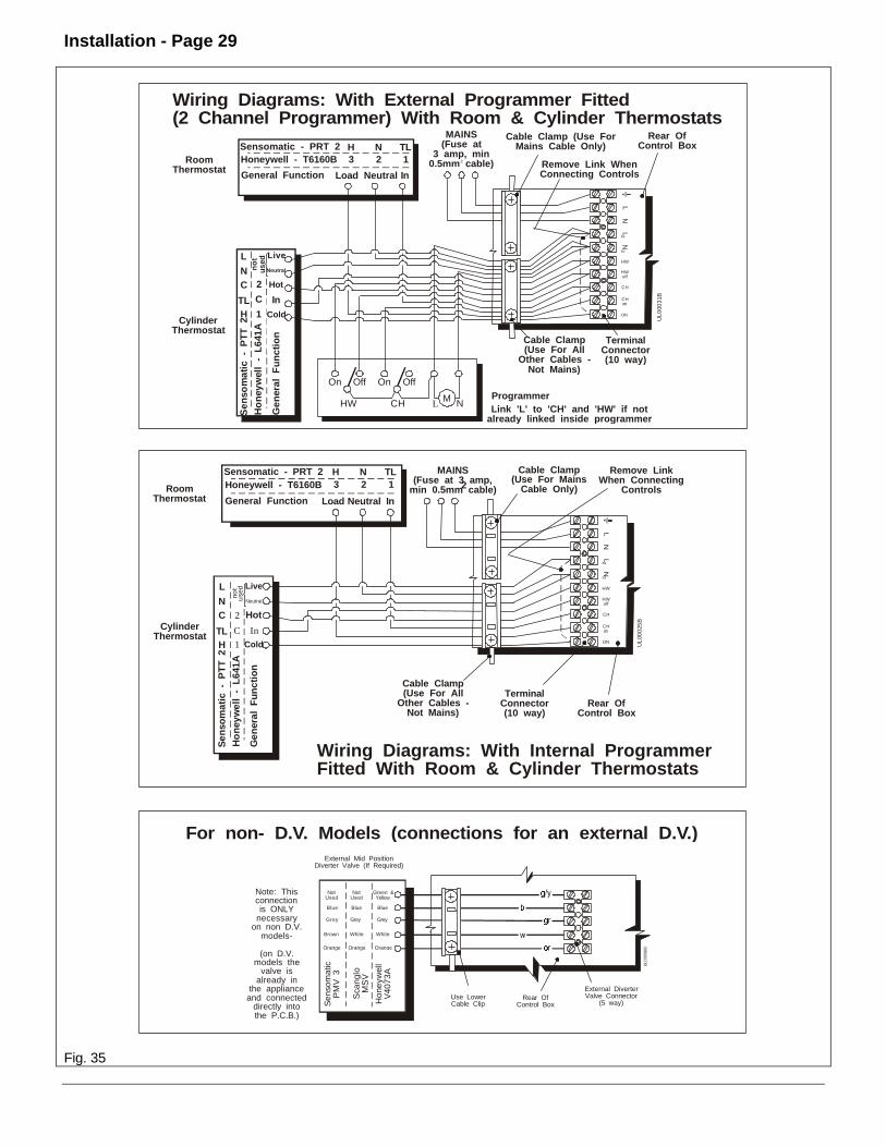
2. Two cable clamps are provided on the back of thecontrol box, use one just for the mains supply and theother for any other external wiring. Slacken thenecessary cable clamp screws. Feed the power supplycable up and over the back of the chassis, through theuppermost clamp and into the terminal connection.Connect the wires, brown to L and blue to N andgreen/yellow to earth ().
Note: When connecting the power supply cable, ensurethat the length of the earth wire is such, that if thepower supply cable pulls out of the cable clamp the liveand neutral wires become taut before the earth wire.
3. Any external control wiring should be routed up andover the back of the chassis, through the lower cableclamp and connect to the terminal connection.
4. Take up excess slack in the power supply cablebetween the terminal block and the cable clamp, thentighten the cable clamp screws. Repeat for any wiresthrough the other cable clamp.
Note: If the optional internal programmer is to be fitted,do so now - See Section 2.11 overleaf.
5. Sufficient slack is available to the cable clamps to alllowpivotel movement.
6. Secure the control box to the thermostat bracket usingthe screw previously removed.Ensure enough cable slack is allocated to allow theControl Box door to open and close.
7. Carry out preliminary electrical system checks i.e. EarthContinuity, Short Circuit, Polarity and Resistance toEarth.
Do not switch on the electricity supply at this stage.
Installation - Page 29
UL
000
31B
TerminalConnector(10 way)
Rear OfControl Box
NN
LL
22
CH
HWoff
HW
CHon
ON
Remove Link WhenConnecting Controls
Cable Clamp (Use ForMains Cable Only)
Gen
eral
Fu
nct
ion
In
Hot
Live
Neutral
Cold
Sensomatic - PRT 2 TLNH
General Function Load Neutral In
Honeywell - T6160B 123RoomThermostat
CylinderThermostat
ProgrammerLink 'L' to 'CH' and 'HW' if not
already linked inside programmer
Cable Clamp(Use For All
Other Cables -Not Mains)
Sen
som
atic
- P
TT
2
TL
CN
L
H
Ho
ney
wel
l -
L64
1An
ot
used
2
C
1
MAINS(Fuse at
3 amp, min0.5mm cable)2
M
On OnOff
HW CH L N
Off
Wiring Diagrams: With External Programmer Fitted(2 Channel Programmer) With Room & Cylinder Thermostats
Cable Clamp(Use For Mains
Cable Only)
Gen
eral
Fu
nct
ion
In
Hot
Live
Neutral
Cold
Sen
som
atic
- P
TT
2
TL
CN
L
H
CylinderThermostat
Cable Clamp(Use For All
Other Cables -Not Mains)
Ho
ney
wel
l -
L64
1Ano
tu
sed
2
C
1
MAINS(Fuse at 3 amp,
min 0.5mm cable)2
UL
000
25B
TerminalConnector(10 way)
Rear OfControl Box
NN
LL
22
CH
HWoff
HW
CHon
ON
Remove LinkWhen Connecting
Controls
Sensomatic - PRT 2 TLNH
General Function Load Neutral In
Honeywell - T6160B 123RoomThermostat
Wiring Diagrams: With Internal ProgrammerFitted With Room & Cylinder Thermostats
UL
00
096
B
External DiverterValve Connector
(5 way)
External Mid PositionDiverter Valve (If Required)
Note: Thisconnectionis ONLY
necessaryon non D.V.
models-
(on D.V.models the
valve isalready in
the applianceand connected
directly intothe P.C.B.)
Rear OfControl Box
Use LowerCable Clip
Orange
White
Grey
Blue
Green &Yellow
Hon
eyw
ell
V40
73A
Orange
White
Grey
Blue
NotUsed
Sca
nglo
MS
V
Orange
Brown
Grey
Blue
NotUsed
Sen
som
atic
PM
V 3
For non- D.V. Models (connections for an external D.V.)
Fig. 35
Installation - Page 30
Fig. 36
2.11 Install the Optional Ultra 2Programmer
1. Connect the programmers electrical plug onto thesocket on the back of the control box.
2. Carefully remove the blanking panel from the facia (thefacia label is self adhesive), locate the programmer intothe cut out, position the retaining bracket and secureusing the screws supplied with the programmer.
3. Leave the facia hanging down for the time being.
2.12 Connect the Gas Supply
Connect the gas supply using a suitable adaptor to the gascock.
The pipe diameter required will depend on the boiler modeland the pipe length from the gas meter. 15mm dia. pipe willbe adequate for the following lengths:
These lengths must be reduced by 0.5m for each elbow andtee fitted.
Longer lengths will require the use of 22mm diameter pipe.
Note: The gas supply must be from below, as the boilerchassis extends below the gas cock.
Do not turn the gas supply on at this stage.
Installation - Page 31
2.13 Connect the Water System& Vent the Boiler
1. Ensure that the plastic plugs are removed from the pipeends and attach the isolation valves. Check the valvesare open.
2. Install the pressure relief valve discharge pipe (min.15mm dia.) and connect to the pressure relief outletusing a 15mm compression fitting. This will enable theconnection to be undone if the boiler has to beremoved.
Important: The pipe run should be as short aspossible, run continuously downwards and dischargeoutside the building and over a drain. It must notdischarge above an entrance, window, any type ofpublic access point, any point where it would behazardous to occupants or cause damage to externalelectrical components or wiring.
3. Screw the pressure gauge connection into the watermanifold, leave the facia hanging down.
4. Fill the system, ensure that all valves are open.
Dv Models Only: The manual lever on the left handside of the diverter valve, must be moved from 'AUTO'to 'MID' (manual override) when filling, venting ordraining the system.
Thoroughly flush the system through. A radiator type airvent is positioned on the left hand side (at the front) ofthe heat exchanger (on 80 models a second vent ispositioned at the rear).
5. Refill and vent the system.6. The pump bearings and shaft rely on system water to
provide lubrication. It is important therefore to ensurethat the bearings have been properly vented and thatthe pump is not run dry otherwise damage may occurto the bearings. Unscrew the pump manual restartknob, and withdraw it to engage in the motor shaft.Rotate the knob and check that the motor shaft rotatesfreely. Apply a sideways pressure to the knob until asmall amount of water becomes visible. The pump isnow vented. After use, the manual restart knob shouldbe screwed back into its original position, finger tight.Take care not to allow any water to drip onto the controlbox or other electrics.
7. Pressurise the system to 1.5 bar and check for leaks,rectifying where necessary. Reset the system pressureto 0.8 bar and set the red adjustable pointer on thepressure gauge to 0.8 bar.
Fig. 38
3. Commissioning - Page 32
UL0
0046
B
COM
P AC
T
Fan & DiverterAssembly
Flue Sampling Point
L.H. Flue Outlet
Flexible Tube Fan
Overheat Thermostat(R.H. Side On 60
& 80 Models)
Heat Exchanger
Insulation
ThermostatPhial
Burner Injector
Main Burner
Gas Valve Outlet Pipe
Programmer(Optional)
Main Burner Pressure Adjusting Screw
CombustionChamber
ExpansionVessel
Flue Hood
R.H. FlueOutlet
Cable Clips
VerticalFlue Outlet
PilotAssembly
IgnitionBoard
HeatShield
Pump
PressureGauge
ThermostatKnob
Test SwitchReset
Button
0
12 12
3
4
5
6
7
8
9
101112
1
112
3
4
5
6
7
8
9
1011
Off
Twice
Once
On
HWADV
CHADVPM AM
Flame
Lockout 5
6
2 bar
1
4
Switch off electricitybefore removing this
cover
- Thermostat +
InletPressure
Test Point
Gas Valve
BurnerPressure
Test Point
IgnitionBoard
IndicatorLights
Sw
itched Liv
e
Perm
anent
Liv
e
Pola
rity
Reve
rsed
Fig. 39
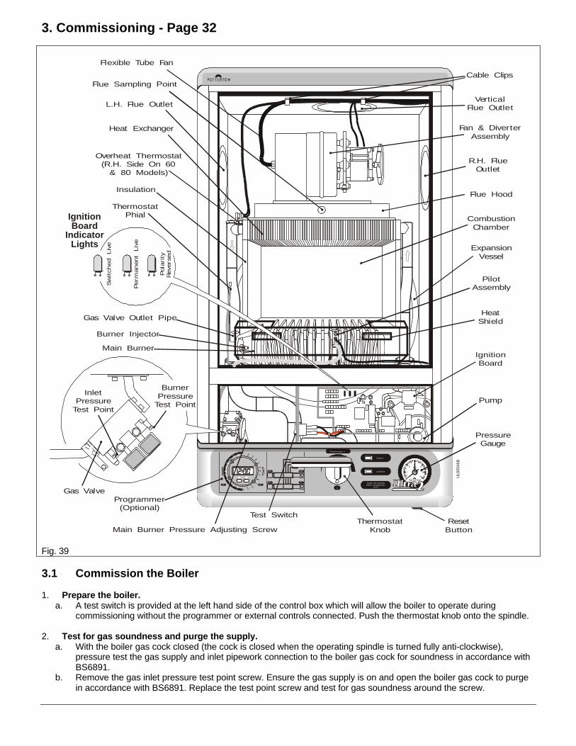
3.1 Commission the Boiler
1. Prepare the boiler.a. A test switch is provided at the left hand side of the control box which will allow the boiler to operate during
commissioning without the programmer or external controls connected. Push the thermostat knob onto the spindle.
2. Test for gas soundness and purge the supply.a. With the boiler gas cock closed (the cock is closed when the operating spindle is turned fully anti-clockwise),
pressure test the gas supply and inlet pipework connection to the boiler gas cock for soundness in accordance withBS6891.
b. Remove the gas inlet pressure test point screw. Ensure the gas supply is on and open the boiler gas cock to purgein accordance with BS6891. Replace the test point screw and test for gas soundness around the screw.
Commissioning - Page 33
3. Check the ignition sequence.With the gas supply isolated check the ignition sequence as follows:
a. Set the test switch to 'Override'.Note: Three indicator lamps are included on the ignition board to aid electrical commissioning. The correctsequence of lights when there is a call for heat is: Permanent Live 'On', Switched Live 'On', Reversed Polarity 'Off'.
b. Switch on the electricity supply and turn the thermostat knob fully clockwise. The automatic ignition sequence willcommence. The fan will start and after a short purge period a click will be heard indicating that the start gassolenoid has opened, ignition sparks will also be heard. The ignition sparks will continue until the pilot is lit but asthe gas supply is not yet turned on the ignition sparks will continue until either the electricity supply is switched off orthe thermostat knob is turned off (fully anti-clockwise).
c. Turn the thermostat knob fully anti-clockwise to terminate the ignition sequence.
4. Check the pilot flame and test the pilot supply for gas soundness.a. Ensure that the gas and electricity supplies are on, the thermostat knob is turned fully anti-clockwise and the test
switch is set to 'Override'.b. Turn the thermostat knob fully clockwise. The unit will go through the ignition sequence. The pilot will light and a
second or so after the pilot has lit the main gas solenoid will open and the main burner will light.c. During the short pilot only period, check that the flame is 35 to 40 mm long and envelops the electrode.
The pilot throttle is factory set fully open (turning the throttle clockwise reduces the flame).d. Turn the thermostat knob fully anti-clockwise. Re-fit the combustion chamber cover and secure with the screws
previously removed. Turn the thermostat knob fully clockwise, to relight the boiler.e. Test the pilot supply connections at the gas valve and pilot assembly for gas soundness using a suitable leak
detecting fluid.f. Turn the thermostat knob fully anti-clockwise.
5. Test the main burner supply for gas soundness.a. Ensure that the gas and electricity supplies are on, the thermostat knob is turned fully anti-clockwise and the test
switch is set to 'Override'.b. Turn the thermostat knob fully clockwise. The unit will go through the automatic ignition sequence and the pilot will
light. A second or so after the pilot is lit the main gas solenoid will open and the main burner will light.c. Test the main burner manifold connection at the gas valve for gas soundness using a suitable leak detecting fluid.
6. Check the main burner setting pressure.After the main burner has been alight for 10 minutes:
a. Turn the thermostat knob fully anti-clockwise. Remove the burner pressure test point screw on the gas valve andconnect a pressure gauge. The pressure increases in two stages, to a 1st step for a few seconds then to fullpressure.
Note: The boiler is factory set to the maximum input, the 1st step pressure is also factory set and should not requirefurther adjustment. See Technical Data, Page 3, for the boiler ratings and setting pressures.The adjusting screw is covered by a plastic cap, carefully prise this off with a suitable screwdriver and replace afteradjusting the pressure.
b. Turn the thermostat knob fully clockwise and check the burner setting pressure.Turn the adjusting screw clockwise to decrease the setting pressure.
c. Turn the thermostat knob fully anti-clockwise, disconnect the pressure gauge and replace the pressure test pointscrew. Turn the thermostat knob fully clockwise to light the main burner and test for gas soundness around thepressure test point screw using a suitable leak detecting fluid. Turn the thermostat knob fully anti-clockwise to turnthe boiler off.
7. Complete the commissioning.a. Check that the arrow on the data label (positioned on the left hand side of the chassis next to the gas valve) is
against the correct boiler rating.b. Switch off the electricity supply to the boiler.c. Set the test switch to 'Normal' if a programmer or external controls are used.
Note: The pilot burner is turned off every time the main burner is off. The ignition sequence is automatically activatedwhen the boiler thermostat requires heat. The boiler is fitted with two neons, a green one that lights when the mainburner is alight and a red neon that will light if the boiler has locked out. If the boiler does lock out a re-set button islocated under the front of the boiler at the right hand side.
Commissioning - Page 34
3.2 Check the Water System
1. When the system has been tested, ensure that the boiler is turned off. Drain the water while it is still hot, in order tocomplete the flushing process.
2. Where the boiler is used on an old system, special care is required. The system should be drained and flushed out,ensuring that all the radiators are drained. Also check the radiator valves.
3. In areas with hard or aggressive water, we recommend that an inhibitor, suitable for use with copper tube boilers,should be used in accordance with the manufacturers instructions.
4. Refill, vent the system, boiler and pump.5. Pressurise the system to 1.5 bar and check for leaks, rectifying where necessary.6. The Boiler Thermostat is factory set & sealed, this MUST NOT be tampered with.
3.3 Balance the System
1. Fully open all the radiator lock shield valves and set any thermostatic radiator valves to maximum.2. With the electricity supply on and the test switch set to 'Override', turn the thermostat knob fully clockwise to light the
boiler.3. Balance the system using the radiator lock shield valves to give a temperature drop of 10°C across the individual
radiators - start with the radiator nearest to the boiler.4. Turn the thermostat knob fully anti-clockwise to turn the boiler off.5. Set the test switch to 'Normal' if a programmer or external controls are used.
3.4 Complete the Boiler
1. Hook the base plate onto the rear of the chassis and secure at the front using the screw previously removed.2. On rear/vertical/vertex flues locate the white case side(s) and secure to the front of the boiler using the screws
previously removed.3. Hook the white front case on at the top of the boiler, position so the ball studs align with the holes in the white case
sides and push firmly to engage them.4. Locate the facia assembly onto the front of the boiler and secure to the white case sides using the two countersunk
screws previously removed.
3.5 Light the Boiler
If a programmer is fitted refer to the Instructions for Use on how to set the programmer.
Do not attempt to light the boiler if the system pressure is less than 0.5 bar. Pressurise the system to 1.5 bar and check forleaks, rectifying where necessary. Adjust the pressure down to 0.8 bar.
With the gas supply on and the electricity supply off.1. Turn the thermostat knob fully anti-clockwise to 0 (Off).2. Switch on the electricity supply, set the programmer to continuous, if a programmer is fitted and check that all system
controls are calling for heat.3. Turn the thermostat knob fully clockwise to maximum. The automatic ignition sequence will commence. The fan will
start and after a short purge period a click will be heard indicating that the start gas solenoid has opened, the ignitionsparks will also be heard. The pilot will light and after a second or so the main gas solenoid will open and the mainburner will light.A green neon, positioned on the facia, will light whenever the main burner is alight.Note: The pilot burner is turned off every time the main burner is off. The ignition sequence is automatically activatedwhen the boiler thermostat requires heat.
4. If a programmer is fitted, ensure that the timer is set to the correct time and the programme is set to the requiredsettings. Ensure that the test switch is set to 'Normal'.
Commissioning - Page 35
3.6 Advise the User
1. If a programmer is fitted, set the timer to the correct time and programme the required settings. For a wall mountedprogramer, see separate programmer instructions. For the Ultra 2 programmer, see the boiler Instructions for Use.
2. Hand the Instructions for Use, these Installation & Service Instructions (and the programmer instructions) to the Userand instruct in the safe operation of the boiler and controls.
3. Advise the User of the precautions necessary to prevent damage to the system and to the building in the event of thesystem remaining inoperative during frost conditions.
4. Advise the User that for continued efficient and safe operation of the boiler it is important that adequate servicing iscarried out at least once a year by the local Gas Region or a C.O.R.G.I. registered Installer.
5. Advise the User how to 'Top Up' the system, to maintain pressure.
6. Leave a permanent card attached to the boiler giving:a. Name and address of installer.b. Date of installation.c. A wiring diagram of the circuit.
4. Annual Service
To ensure continued efficient operation of the appliance, it is recommended that it is checked and cleaned as necessary atregular intervals.The frequency of servicing will depend upon the particular installation conditions and usage but in general once per yearshould be adequate.It is the law that any service work must be carried out by a competent person such as British Gas or other C.O.R.G.I.Registered Personnel.
The following aspects of the boiler and installation should be examined, and rectified as necessary.
1. Check that the system pressure is 0.8 bar (cold).
2. Run the boiler and check the operation of its controls and ensure that it responds to any switches and programmer.
3. Check the installation of the flue terminal and ensure it is not obstructed.Note: A flue sampling point has been provided on this boiler. It is accessible after removal of the white front case, andremoval of the 17mm A/F hexagon head bolt from the combustion chamber cover.
If it is necessary to dismantle the boiler the following checks should be made.1. Remove the combustion fan and ensure that it is clean and free of debris. Check the impellor for freedom of
rotation.2. Remove the combustion chamber front and check if the burner or heat exchanger requires cleaning.3. Examine the main injector orifice and ensure it is clear and undamaged.4. If a sufficiently large pilot flame cannot be achieved examine the pilot injector orifice to ensure it is clear and
undamaged. (See Fig. 54).5. When refitting the inner case front panel check that the seals are in good condition and compress satisfactorily.
On completion of the service run the boiler and ensure that it operates satisfactorily.The Boiler Model and Serial Number/Code, are given on the Data Badge.The boiler data label is on the left hand side of the chassis next to the gas valve.
WARNINGBefore commencing work open the control panel cover (hinges down) and turn the thermostat knob to O (Off).
Allow the boiler to cool, isolate the electricity supply and turn off the gas at the gas service cock.
IMPORTANTAlways test for gas soundness after completing any servicing of gas carrying components and carry out functional
checks of controls.
5. Routine Maintenance - Page 36
5.1 Remove the Case
Ensure that the electricity supply is off.
1. Pull down the control cover flap to expose the facia. Remove the 2 screws securing the facia to the side panels andremove the facia/control cover carefully unclipping the two neons as you pull the facia away.
Note: If required, disconnect the programmer harness from the rear of the control box. The facia can only becompletely removed from the boiler if the pressure gauge connection is unscrewed and the boiler drained.
2. Pull the bottom of the white front case forward to release the bottom ball studs, continue pulling until the top studsrelease, then lift slightly and pull away from the boiler.
3. Place the case parts safely aside to avoid possible damage.
5.2 Dismantle the Boiler
1. Turn off the gas supply at the gas cock (bottom L.H. corner).2. Remove the four screws (two at the top and two at the bottom) securing the combustion chamber cover.3. Disconnect the overheat thermostat leads.4. Remove the two screws securing the fan assembly to the flue hood. Carefully slide the fan assembly away from the flue
to disengage the flue tube sleeve from the flue. Withdraw the fan assembly, disconnecting the fan motor leads andpressure switch tube.Note: If a Vertex or Vertical Flue is fitted, slide the flue tube sleeve up into the flue to disengage it from the fan outlet.
5. Remove the four screws securing the flue hood - two at the back (extended screws) and two at the front (30 to 60Models), or two either side (80 models).
6. Lift the flue hood off the boiler.7. Remove the two screws securing the burner heat shield to the combustion chamber insulation cover and remove the
shield.8. Remove the two screws securing the combustion chamber insulation cover and remove the cover.9. Undo the securing nut and remove the spark electrode, from the pilot assembly.10. Undo the tubing nut and disconnect the pilot supply from the pilot assembly.
Carefully remove and retain the pilot injector.11. Remove the two screws securing the right hand end of the burner to the chassis. Slide the burner to the right, to
remove it from the main injector and withdraw the burner.
5.3 Cleaning the Boiler
1. Brush the heat exchanger from above and below using a suitable brush. Brush back to front NOT sideways. Removeany fallen deposits from the base of the chassis.
2. Brush the burner top and check that the flame ports are clear. Any blockage may be removed with a fine wire brush.Turn the burner open end down and tap gently to remove any debris.
3. If the pilot burner requires cleaning, remove the two screws securing it to the burner and remove, clean the burner headwith a fine wire brush, then refit it to the main burner.
4. Check the condition of the spark electrode, clean with a fine wire brush if necessary.5. Unscrew the main injector from the burner manifold (do not lose the sealing washer and on the 80 models an additional
spacer), clean by blowing through or washing. Do NOT clear the injector with a pin or wire. Clean the pilot injector in asimilar manner.
6. Re-fit the main injector - do not forget to fit the sealing washer and on the 80 models the spacer.7. Remove the four screws securing the fan to the diverter (make a note which way the fan is fitted). Examine the fan
impellor and carefully clean if necessary. Refit the fan to the diverter.
5.4 Re-assemble the Boiler
1. Re-assemble the boiler in reverse order. Also note the following points:-a. After refitting the spark electrode, check that the spark gap is 3 to 4mm.b. Ensure that the pilot supply and electrode lead pass through the white silicone grommet in the bottom of the
chassis.c. The polarity is not important when re-connecting the overheat thermostat leads.d. Referring to the Commissioning Instructions(Page 32), light the pilot and check the flame, test the pilot supply for
gas soundness and check the main burner setting pressure.
Routine Maintenance - Page 37
6. Replacement Of Parts - Page 38
WARNING: Before commencing work open, the control panel cover (hinges down) and turn the thermostat knob to O (Off).Allow the boiler to cool and isolate the electricity supply. Turn off the gas at the gas service cock.
IMPORTANT: Always test for gas soundness after completing any exchange of gas carrying components and carry outfunctional checks of controls.
All Models: When removing and replacing any parts that involve draining the system, close the boiler isolation valves andthen drain the boiler using the presure gauge connection. DO NOT use the safety valve to drain the boiler.Dv Models: When removing and replacing any parts that involve draining the system, the manual lever on the left hand sideof the diverter valve must be moved to the 'MID' (manual override) position. Return it to its original position after the systemhas been filled and vented.Non-Dv Models with external diverter valve: When removing and replacing any parts that involve draining the system, itmay be necessary to move a lever on the diverter valve, see manufacturers instructions for the particular valve. Return it toits original position after the system has been filled and vented.
6.1 General Access
1. Replacement of any component requires the removal ofthe facia assembly and white front case as follows:
a. Pull down the control cover flap to expose the facia.Pull off the thermostat control knob. Remove the 2screws securing the facia to the side panels andremove the facia/control cover, carefully unclippingthe two neons as you pull the facia away.
Note: The facia can only be completely removed fromthe boiler if the pressure gauge connection isunscrewed and the boiler drained. If fitted, disconnectthe programmer harness from the rear of the controlbox.
b. Pull the bottom of the white front case forward torelease the bottom ball studs, continue pulling untilthe top studs release, then lift slightly and pull awayfrom the boiler.
c. Place the case parts safely aside to avoid possibledamage.
d. Remove the screw and unhook the bottom cover.e. Turn off the gas supply to the boiler at the gas
service cock (bottom L.H. corner).f. Turn off the water supply to the boiler at the
isolation valves.g. If required, remove the screw and swing out the
control box.
2. Sections 6.14 to 6.21 involve replacement ofcomponents within the room-sealed section of theboiler. All necessitate the removal of the combustionchamber cover as follows:
a. Remove the four screws securing the combustionchamber cover and lift it off.
b. Remove the two screws and lift off the burner heatshield.
Re-assemble all parts in reverse order.
Replacement of Parts - Page 39
6.2 Gas Valve
1. Gain General Access - See Section 6.1, Paragraph 1.2. Slacken the retaining screw and disconnect the gas
valve electrical plug from the valve.3. Disconnect the pilot supply from the top of the gas
valve.4. Undo the union at the gas service cock.5. Remove the four 3 mm socket screws securing the gas
valve to the burner manifold.6. Remove the screw securing the inlet manifold to the
side of the chassis, withdraw the gas valve.7. Remove and discard the 'O' ring in the burner manifold.8. Remove the four 3mm socket screws securing the inlet
manifold and fit it to the new valve, using a new 'O' ring(both 'O' rings are the same).
9. With a new 'O' ring in the burner manifold secure thenew valve to the manifold using the four socket screwspreviously removed.
10. Reconnect the pilot supply, gas service cock union,plug and secure the inlet manifold to the chassis.
11. Open the gas service cock and test the union and inletmanifold to gas valve connection for gas soundness.
12. Referring to the Commissioning Instructions, light theboiler, test the pilot supply and burner manifoldconnections at the gas valve for gas soundness. Adjustthe burner pressure setting to give the correct rating asshown by the arrow on the data label, then adjust the1st step pressure to that shown in the Technical Dataon Page 3.
13. Re-assemble in reverse order. Ensure the harness isrouted through the cable ties as shown in Figs 40 / 41.
6.3 Gas Valve Solenoids
1. Gain General Access - See Section 6.1, Paragraph 1.2. Slacken the retaining screw and disconnect the gas
valve electrical plug from the valve.3. Remove the screw securing the solenoids mounting
bracket and carefully withdraw the mounting bracket,complete with solenoids, from the valve.
4. Position the new solenoids in the mounting bracket,refit the mounting bracket.
5. Reconnect the plug to the gas valve and re-assembleall remaining parts in reverse order.
6. Refer to the Lighting Instructions on Page 34 and lightthe boiler.
Replacement of Parts - Page 40
6.4 Pump Head/Pump Complete
Pump Head
1. Gain General Access - See Section 6.1, Paragraph 1.2. Remove the screw securing the pressure switch to the
chassis and move the switch out of the way.3. Remove the two screws securing the thermostat
bracket to the chassis and move it out of the way.4. Remove the two pump wiring cover screws, remove the
cover and disconnect the wires.5. Using an allen key, remove the four allen bolts and
remove the pump head.6. Position the new pump head and secure using the four
allen bolts.7. Connect the wires to the new pump as shown. Vent the
pump as shown in Section 2.13
Pump Complete
1. Perform steps 1 to 4 above.2. Place a cloth under the pump as it will contain a small
amount of water when removed.3. Loosen the two pump unions, taking care not to twist
the pipework. Support the pump,fully release the twounions and withdraw the pump.
4. Position the new pump (use two new sealing washers)ensuring the arrow on the side of the pump pointsupwards and fully tighten the unions.
5. Rewire the pump as shown.6. Vent the pump as described in Section 2.13 and check
the pump connections for water soundness.7. Re-assemble in reverse order.
6.5 Air Pressure Switch
1. Gain General Access - See Section 6.1, Paragraph 1.2. Carefully disconnect the flexible tubes and the three
leads from the pressure switch.3. Slacken the screw securing the pressure switch
mounting bracket to the boiler chassis. Note how thepressure switch is secured by the bracket and removethe switch.
4. Reconnect the pressure switch leads as follows:Yellow to 'NO', Red to 'NC' and Black to 'C'.
5. Locate the new pressure switch under the mountingbracket and fully tighten the securing screw.
6. Re-assemble in reverse order.
Replacement of Parts - Page 41
6.6 Diverter Valve HeadDv Models Only
1. Gain General Access - See Section 6.1, Paragraph 1.2. Disconnect the diverter valve head wiring harness plug
from the ignition circuit board.3. Remove the two screws securing the diverter valve
head to the main body and lift off the head.4. Fit the diverter valve head to the valve body (operating
lever at the left hand side), ensuring that the shaft seatscorrectly. Secure the head in position with the two newscrews supplied.
1. Gain General Access - See Section 6.1, Paragraph 1.2. Drain the boiler by removing the pressure gauge
connection from the water manifold.Note: When the boiler is drained, filled or vented, themanual lever on the left hand side of the diverter valvemust be moved to the 'MID' (manual override) position.Return it to its original position after the system hasbeen filled and vented.
3. Compress the clips on the body of the gauge and pushit out of the panel, withdrawing the capillary.
4. Fit the new pressure gauge and connect the sensor tothe safety valve using a new sealing washer.
5. Fill the system and vent the boiler as described inSection 2.13. Check the pressure gauge connection atthe water manifold for water soundness.
6. Re-assemble in reverse order.
Replacement of Parts - Page 42
6.8 Pressure Relief Valve
1. Gain General Access - See Section 6.1, Paragraph 1.2. Drain the system by removing the pressure gauge
connection from the water manifold.Note: When the system is drained, filled or vented, themanual lever on the left hand side of the diverter valvemust be moved to the 'MID' (manual override) position.Return it to its original position after the system hasbeen filled and vented.
3. Disconnect the compression joint securing thedischarge pipe to the valve.
4. Remove the two grub screws (top & bottom) thatsecure the valve to the water manifold then remove thevalve.
5. Fit the new valve and a new 'O' ring. Use a soapsolution as a lubricant.
6. Re-assemble in reverse order.
6.9 By-Pass Valve
1. Gain General Access - See Section 6.1, Paragraph 1.2. Drain the system by removing the pressure gauge
connection from the water manifold.Note: When the system is drained, filled or vented, themanual lever on the left hand side of the diverter valvemust be moved to the 'MID' (manual override) position.Return it to its original position after the system hasbeen filled and vented.
3. Release the two unions securing the valve to the watermanifold and by-pass pipe. Remove the valve.
4. Fit the new valve, use a new washer at the connectionwith the water manifold and check the condition of theolive at the connection with the by-pass pipe.Note: The spare by-pass valve is pre-set and must notbe adjusted.
5. Fill and vent the boiler as described in Section 2.13.Check the unions for water soundness.
6. Re-assemble in reverse order.
Replacement of Parts - Page 43
6.10 Ignition Circuit Board
1. Gain General Access - See Section 6.1, Paragraph 1.2. Disconnect all wiring harness connectors and the
electrode lead from the board. The programmer socketis released by gently compressing the mounting clipwith a screwdriver, also release the earth lead from theearth post.
3. Carefully remove the circuit board from the mountingpillars and replace with a new one.
4. Reconnect the wiring harness connectors and theelectrode lead.
5. Re-assemble in reverse order.
6.11 Reset Button/Neons
Note: The neons and the reset button are one assembly andmust be replaced complete.
1. Remove the bottom cover and facia assembly - SeeSection 6.1, Paragraphs a. & d. Removal of the airpressure switch (Section 6.5) will allow the reset buttonto be slid out to the left.
2. Disconnect the harness from the circuit board.3. Compress the clips on the side and pull the reset button
through the chassis.4. Re-assemble in reverse order.
1. Gain General Access - See Section 6.1, Paragraph 1.2. Note how it fits and unplug the programmer wiring
harness plug from the back of the control box.3. Remove the two screws that secure the retaining
bracket over the programmer and onto the facia.Remove the bracket.
4. Fit the new programmer to the back of the controlpanel, position the bracket and secure using the twoscrews previously removed.
5. Connect the programmer wiring harness plug into therear of the control box.
6. Re-assemble in reverse order.7. Switch on the electricity supply, refer to the
Programmer instructions and set the timer andprogrammes.
Replacement of Parts - Page 44
PL5
PL6
PL9
PL1
0
PL4
PL
1
PL8
PL7
PL3
TestSwitch
Override
Normal
T.S/w
ControlBox
UL00069A
Fig. 52
6.13 Test Switch
1. Gain General Access - See Section 6.1, Paragraph 1.2. Disconnect the two electrical (spade) connectors from
the switch.3. Note which way the switch is fitted, compress the clips
on the switch body and push it out of the control box.4. Fit the new switch as shown with the spade connectors
to the bottom.5. Re-assemble in reverse order.
6.14 Overheat Cut-Off Device
1. Gain General Access - See Section 6.1 complete.2. Disconnect the overheat thermostat leads.3. Remove the two screws securing the overheat
thermostat to the heat exchanger.4. Ensure that the mounting plate is clean, smear some
heat conductive grease onto the plate and secure thenew thermostat to the heat exchanger.
5. Reconnect the leads (the polarity is not important).6. Re-assemble in reverse order.
Replacement of Parts - Page 45
6.15 Electrode Lead/Electrode
Spark Electrode.
1. Gain General Access - See Section 6.1 complete.2. Disconnect the electrode lead from the spark electrode.3. Undo the securing nut and pull the electrode from the
pilot burner.4. Fit the new spark electrode to the pilot burner and
secure using the nut.Check that the spark gap is 3 to 4mm.
5. Connect the electrode lead to the spark electrode.6. Re-assemble in reverse order.
Electrode lead.
1. Gain General Access - See Section 6.1 complete.2. Disconnect the electrode lead from the spark electrode.3. Disconnect the electrode lead from the ignition circuit
board.4. Carefully pull the electrode lead out through the white
silicone grommets in the right side of the chassis.5. Carefully feed the new lead back through the white
silicone grommet.6. Ensure the lead goes around the rear of the control box
and in from the right hand side.7. Re-assemble in reverse order.
Replacement of Parts - Page 46
6.16 Main Burner, Pilot Burner,Main Injector, Pilot Injector
Pilot Injector
1. Gain General Access - See Section 6.1 complete.2. Pull the electrode lead off the electrode.3. Undo the pilot supply pipe tubing nut at the pilot burner
and gas valve. Remove the pilot injector.
Main Burner
Follow steps 1 to 3 plus:-
4. Remove the two screws securing the right hand end ofthe burner to the chassis. Slide the burner to the right toremove it from the main injector and withdraw theburner.
Pilot Burner
Follow steps 1 to 4 plus:-
5. Remove the two screws securing the pilot burner to themain burner.
Main Injector
Follow steps 1 to 4 plus:-
6. Unscrew the main injector from the burner manifold andremove the sealing washer.
On re-assembly of the main injector, use a suitablesealing compound on the threads and also use a newsealing washer.
On re-assembly of the pilot injector, position the injectorover the end of the pilot supply pipe and carefully insertinto the pilot burner.
On re-assembly of the spark electrode check the sparkgap. It should be 3 to 4mm.
7. Re-assemble in reverse order.
Replacement of Parts - Page 47
6.17 Fan
1. Gain General Access - See Section 6.1 complete.2. Disconnect the overheat thermostat leads.3. Remove the two screws securing the fan assembly to
the flue hood. Carefully slide the fan assembly awayfrom the flue to disengage the flue tube sleeve from theflue. Withdraw the fan assembly, disconnecting the fanmotor leads and pressure switch tube.
Note: If a Vertex or Vertical Flue is fitted, slide the flue tubesleeve up into the flue to disengage it from the fan outlet.4. Remove the four screws securing the fan to the diverter
and remove the fan. Remove the flue tube sleeve fromthe old fan. Ensure that the 'O' ring is in position on thefan outlet, then fit the flue tube sleeve over the fanoutlet and push it fully home. Secure the new fan to thediverter with the four screws previously removed.
5. Place the fan assembly on top of the flue hood with theoutlet facing towards the flue. Re-connect the two violetleads (polarity not important) to the fan motor and theair pressure tube to the fan.
6. With the fan assembly resting on the flue hood engagethe flue tube sleeve on the fan outlet into the inner tubeof the flue.Ensure that the base of the fan assembly islocated under the returns at the rear of the flue hood.(For side exit flue locate the base of the fan assemblyunder the returns first then slide the fan across into theflue).
Note: If a Vertex or Vertical Flue is fitted, slide the flue tubesleeve down out of the flue and over the fan outlet.7. Secure the front of the fan assembly to the flue hood
with the two screws previously removed.8. Re-assemble the boiler in reverse order.
Replacement of Parts - Page 48
6.18 Combustion ChamberInsulation Panels
1. Gain General Access - See Section 6.1 complete.2. Remove the fan/diverter assembly - see Section 6.17.3. Remove the four remaining screws securing the
combustion chamber insulation cover and remove thecover.
30-60 Models: Remove the two long screws at theback & slide out the flue hood if the rear insulationneeds to be removed.
80 Model: Remove 2 screws each side.
4. Slide out the damaged insulation panel(s) and carefullyreplace with new one(s).The rear panel should be lifted up a few mm then pulledforwards out of its bottom locating channel.Note: For some models it may be necessary to removethe burner first - refer to Section 6.16.
5. Re-assemble in reverse order.
6.19 Boiler Thermostat
1. Gain General Access - See Section 6.1 complete.2. Remove the two screws securing the thermostat to its
mounting bracket.3. Withdraw the boiler thermostat and disconnect the
electrical plugs.4. Remove the split pin and withdraw the thermostat
capillary from the flow pipe (left hand side of theboiler).
5. Re-assemble in reverse order. Ensure the electricalplugs are connected as shown and that the thermostatcapillary routed through the cable tie(see Fig 40 / 41) and is smeared with heat conductivegrease. Ensure that the split pin is re-fitted.
Replacement of Parts - Page 49
6.20 Heat Exchanger
Note: When removing the heat exchanger it will dischargesome remaining water, suitably protect the electronics.
1. Gain General Access - See Section 6.1 complete.Remove the Main Burner -See Section 6.16Remove the Fan/Diverter Assembly -See Section 6.17Remove the flue hood by taking out two long screws atthe back & the two screws at the front (on 80 modelstwo screws each side). Lift out the flue hood. SeeFig.40, Page 37.
2. Drain the boiler by removing the pressure gaugeconnection from the water manifold.
Note: When the boiler is drained, filled or vented, themanual lever on the left hand side of the diverter valve mustbe moved to the 'MID' (manual override) position. Return it toits original position after the system has been filled andvented.
3. Remove the two screws securing the overheatthermostat to the heat exchanger.
4. Undo the two tubing nuts at the bottom of the heatexchanger and remove it from the boiler - lift it upslightly to disengage the pipes and to clear thecombustion chamber then withdraw it forwards.
5. Fit the new heat exchanger. Refit the overheatthermostat (polarity of wires not important) and securein position with the two screws previously removed.
6. Fill the system and vent the boiler as described inSection 2.13. Check the heat exchanger connectionsfor water soundness.
7. Re-assemble the remaining parts in reverse order
Replacement of Parts - Page 50
6.21 Expansion Vessel
Depending on ease of access, the expansion vessel can beremoved from the left, right or from above the boiler.Alternatively, the boiler can be taken off the wall and thevessel removed from the boiler.
All
1. Gain General Access - See Section 6.1 complete.2. Drain the boiler by removing the pressure gauge
connection from the water manifold.Note: When the boiler is drained filled or vented, themanual lever on the left hand side of the diverter valvemust be moved to the 'MID' (manual override) position.Return it to its original position after the system hasbeen filled and vented.
3. Disconnect the flexible pipe from the water manifold.
Side Removal - Remove the white case side - two screws.
Top Removal - If the flue exits out the rear it will needdisconnecting to allow access.
Boiler off wall - Close all service cocks - water and gas(Section 2.12 & 2.13), isolate electricity supply (Section2.10), remove fan assembly (Section 6.17). Disconnect thewater and gas service cocks, disconnect the electricitysupply and lift the boiler off the wall.
4. Remove the vessel securing bracket(s).5. Remove the vessel.6. Position the new vessel in the frame with the
connection point down and to the right.7. Fill the system and vent the boiler as described in
Section 2.13. Check the expansion vessel connectionfor water soundness.