Installation & Service Manual LFSC5, LF5, LNSC5, LN5 This manual has been designed to be used in conjunction with the General Installation & Service Manual. Save the Instructions in Both Manuals for Future Reference!! This merchandiser conforms to the Commercial Refrigeration Manufacturers Association Health and Sanitation standard CRS-S1-96. PRINTED IN Specifications subject to REPLACES ISSUE PART IN U.S.A. change without notice. EDITION 9/99 DATE 5/04 NO. 9027525 REV. D Tyler Refrigeration * Niles, Michigan 49120 SELF-SERVE SELF-CONTAINED & REMOTE SPOT MERCHANDISERS Low and Medium Temperature Refrigerated Display Cases
Transcript
Installation & ServiceManual
LFSC5, LF5, LNSC5, LN5
This manual has been designed to be used in conjunction with the General Installation & Service Manual.
Save the Instructions in Both Manuals for Future Reference!!This merchandiser conforms to the Commercial Refrigeration Manufacturers Association Health and Sanitation standard CRS-S1-96.
PRINTED IN Specifications subject to REPLACES ISSUE PARTIN U.S.A. change without notice. EDITION 9/99 DATE 5/04 NO. 9027525 REV. D
Tyler Refrigeration * Niles, Michigan 49120
SELF-SERVE SELF-CONTAINED & REMOTE SPOT MERCHANDISERSLow and Medium Temperature Refrigerated Display Cases
Installation & Service Manual LFSC5, LF5, LNSC5, LN5
LNSC5 MEDIUM TEMPERATURE SELF-CONTAINED SPOT MERCHANDISER
LF5 MEDIUM TEMPERATURE REMOTE SPOT MERCHANDISER
LFSC5, LF5, LNSC5, LN5 Tyler Refrigeration
Page 4 November 1999
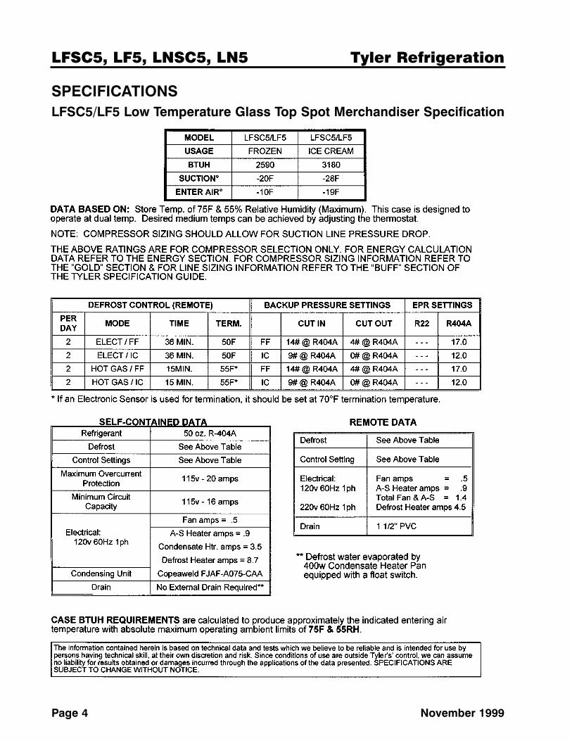
SPECIFICATIONSLFSC5/LF5 Low Temperature Glass Top Spot Merchandiser Specification
Installation & Service Manual LFSC5, LF5, LNSC5, LN5
October, 1996 Page 5
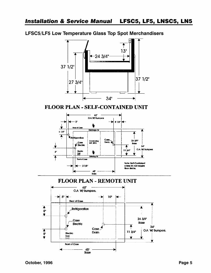
LFSC5/LF5 Low Temperature Glass Top Spot Merchandisers
LFSC5, LF5, LNSC5, LN5 Tyler Refrigeration
Page 6 May, 2004
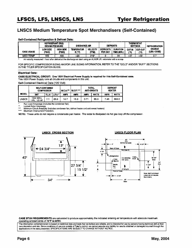
LNSC5 Medium Temperature Spot Merchandisers (Self-Contained)
Installation & Service Manual LFSC5, LF5, LNSC5, LN5
May, 2004 Page 7
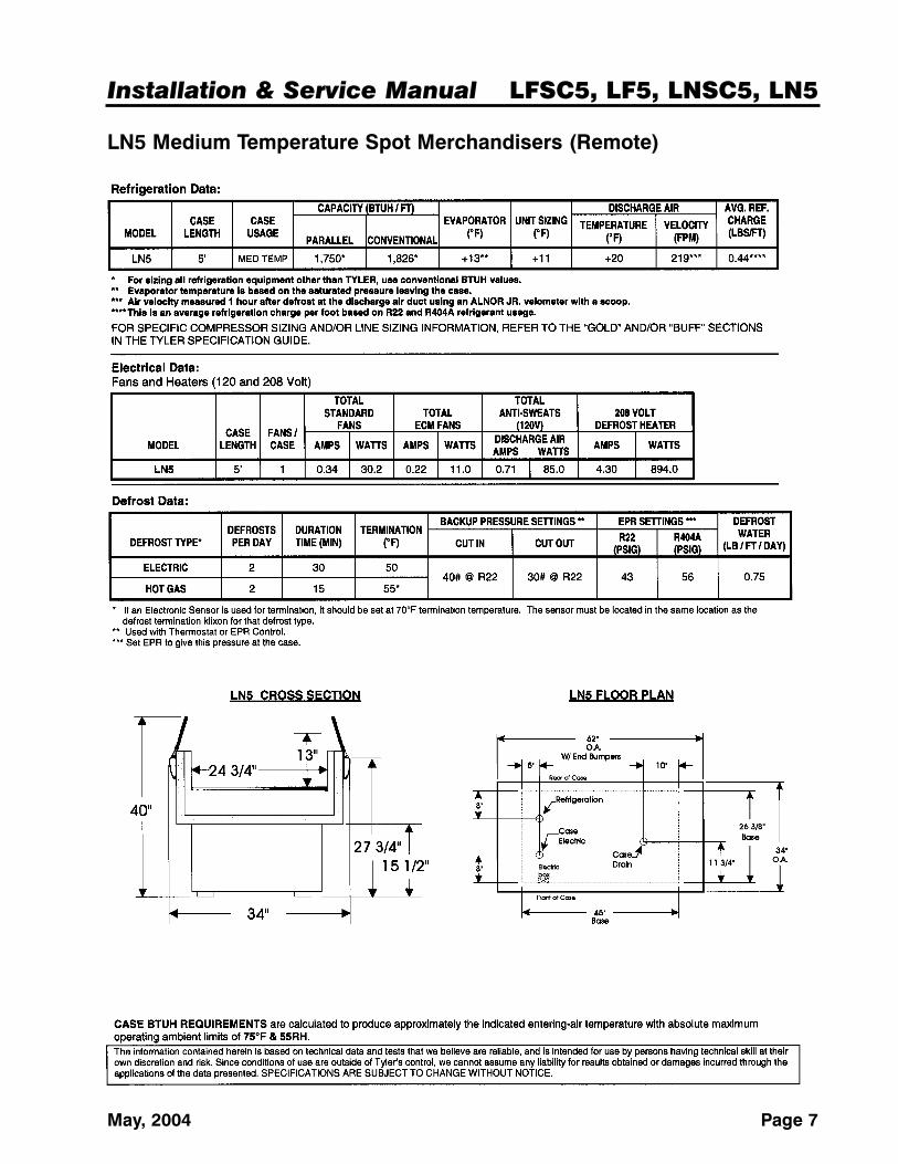
LN5 Medium Temperature Spot Merchandisers (Remote)
LFSC5, LF5, LNSC5, LN5 Tyler Refrigeration
Page 8 May, 2004
INSTALLATION PROCEDURES
Carpentry Procedures
NOTEIf installing LF5 or LN5 remote models, seethe plumbing and refrigeration proceduresections in the “General I&S Manual”.
Electrical Procedures
Electrical Considerations
CAUTIONMake sure all electrical connections aretight. This will prevent burning of electricalterminals and/or premature component failure.
Case Fan Circuit (LF5/LN5 Only)
This circuit is to be supplied by an uninter-rupted, protected 120V circuit. The case fancircuit is not cycled during defrost on any ofthese models.
Self-Contained Circuit (LFSC5/LNSC5 Only)
LFSC5 and LNSC5 cases are self-containedunits. Specific electrical information pertainingto self-contained units should be obtaineddirectly from TYLER Refrigeration.
Installation & Service Manual LFSC5, LF5, LNSC5, LN5
May, 2004 Page 9
LFSC5/LNSC5 Condensing UnitStart-Up and Maintenance
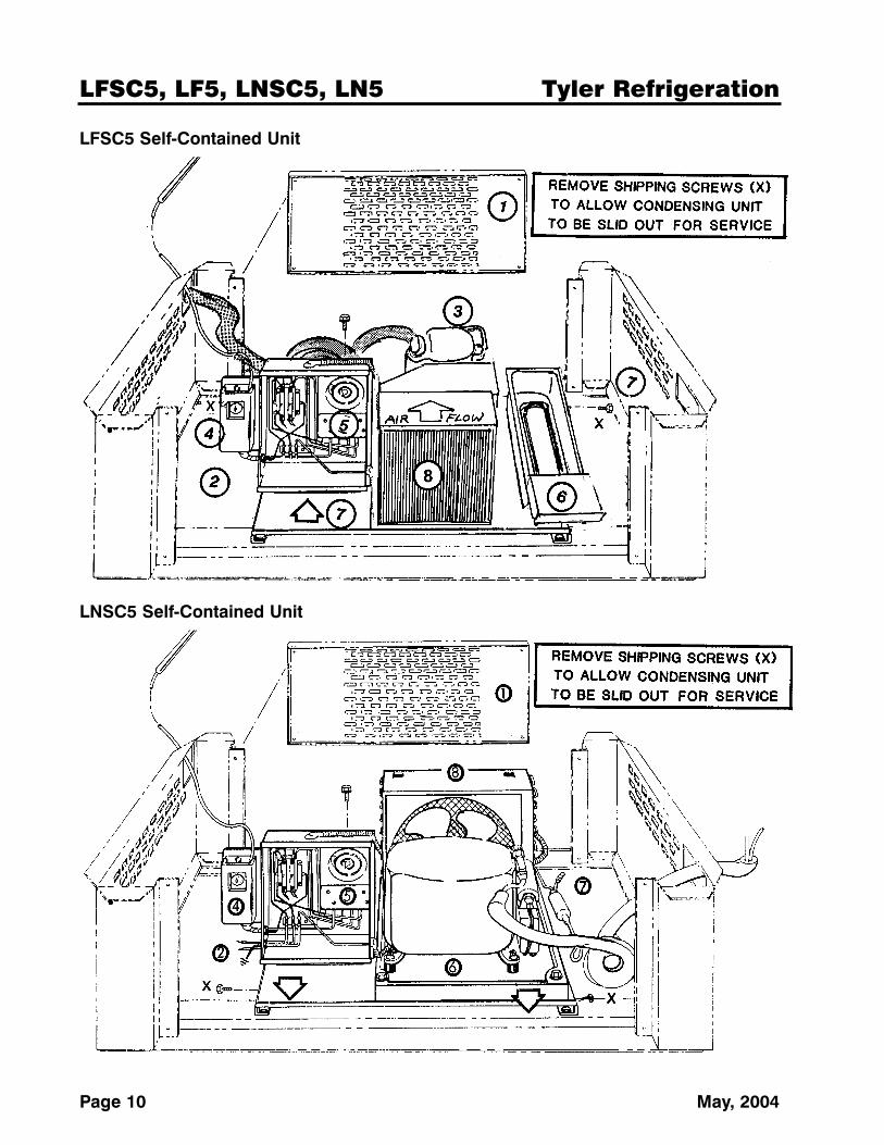
1. Condensing unit access is obtained byremoving the front and rear ventilationpanels.
2. Electrical supply should be wired directlyto the terminal block alongside the defrostclock. Electrical supply should be a 40A,115V 60Hz cicuit. Be sure the case isproperly grounded.
NOTESee “Wiring Diagrams” in this manual forwiring specifics.
3. The compressor is mounted on rubbergrommets. Do not loosen the nuts.
4. Set the thermostat for 0°F to 5°F forLFSC5 or 35°F for LNSC5. A screwdriverwill be required to turn the slotted dial.
NOTEThe sensing bulb should be located in thereturn air. After the air passes through thecoil, it will be about 10° lower.
5. Set defrost control for two defrosts perday at 36 minutes failsafe for the LFSC5or 30 minutes failsafe for the LNSC5.There is a 1000W electric heater whichdefrosts the coil. The defrost limit switchopens at 50°F and turns off the heater.The unit will resume the refrigeration cyclewhen the failsafe is expired.
6. On the LFSC5, the condensate pan isstainless steel and is equipped with a400W heater. The heater is connected toa 190°F limit switch and a float switch toprevent the it from operating when wateris not present.
On the LNSC5, the condensate water iseliminated using the heat from the com-pressor. No resistance electrical heat isrequired. The water from the case coildefrosting makes the unit more efficientwhen water is in the pan.
The pan in either case will not handlewash water! The plastic drain hose canbe pulled out to drain case interior to abucket during cleaning. Be sure toreplace the plastic hose securely aftercleaning.
7. Service pressure access to the system isthrough the Schrader valve and the suc-tion service valve on the compressor. Thecondensing unit is on a slide-out base.
8. Keep the condenser efficient by cleaningit regularly, at least every six months.Clean more frequently if it gets cloggedwith dust in less time. Use a shop vacu-um and/or air pressure to clear the finnedcoil of dust and dirt.
LFSC5, LF5, LNSC5, LN5 Tyler Refrigeration
Page 10 May, 2004
LFSC5 Self-Contained Unit
LNSC5 Self-Contained Unit
Installation & Service Manual LFSC5, LF5, LNSC5, LN5
May, 2004 Page 11
Defrost Information
See “General I&S Manual” for operationaldescriptions for each type of defrost con-trol.
Defrost Control Chart
LFSC5/LF5 Defrost Option SettingsDefrost
Defrost Defrosts Duration Term.Type Per Day (Min) Temp.Electric/FF 2 36 50°FElectric/IC 2 36 50°FGas/FF 2 15 55°FGas/IC 2 15 55°F
LNSC5/LN5 Defrost Option SettingsDefrost
Defrost Defrosts Duration Term.Type Per Day (Min) Temp.Electric 2 30 -----Gas 2 15 -----
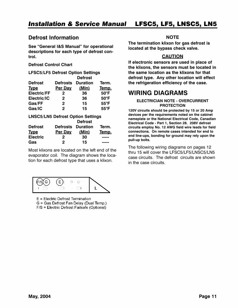
Most klixons are located on the left end of theevaporator coil. The diagram shows the loca-tion for each defrost type that uses a klixon.
NOTEThe termination klixon for gas defrost islocated at the bypass check valve.
CAUTIONIf electronic sensors are used in place ofthe klixons, the sensors must be located inthe same location as the klixons for thatdefrost type. Any other location will effectthe refrigeration efficiency of the case.
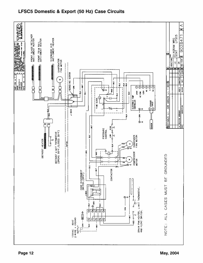
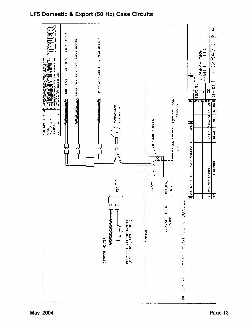
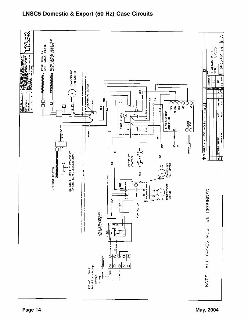
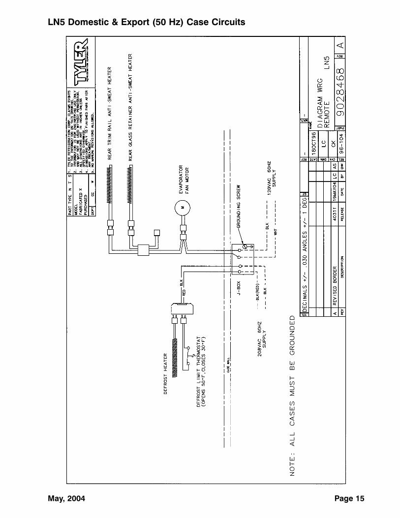
WIRING DIAGRAMSELECTRICIAN NOTE - OVERCURRENT
PROTECTION120V circuits should be protected by 15 or 20 Ampdevices per the requirements noted on the cabinetnameplate or the National Electrical Code, CanadianElectrical Code - Part 1, Section 28. 208V defrostcircuits employ No. 12 AWG field wire leads for fieldconnections. On remote cases intended for end toend line-ups, bonding for ground may rely upon thepull-up bolts.
The following wiring diagrams on pages 12thru 15 will cover the LFSC5/LF5/LNSC5/LN5case circuits. The defrost circuits are shownin the case circuits.
Page 12 May, 2004
LFSC5 Domestic & Export (50 Hz) Case Circuits
May, 2004 Page 13
LF5 Domestic & Export (50 Hz) Case Circuits
Page 14 May, 2004
LNSC5 Domestic & Export (50 Hz) Case Circuits
May, 2004 Page 15
LN5 Domestic & Export (50 Hz) Case Circuits
LFSC5, LF5, LNSC5, LN5 Tyler Refrigeration
Page 16 May, 2004
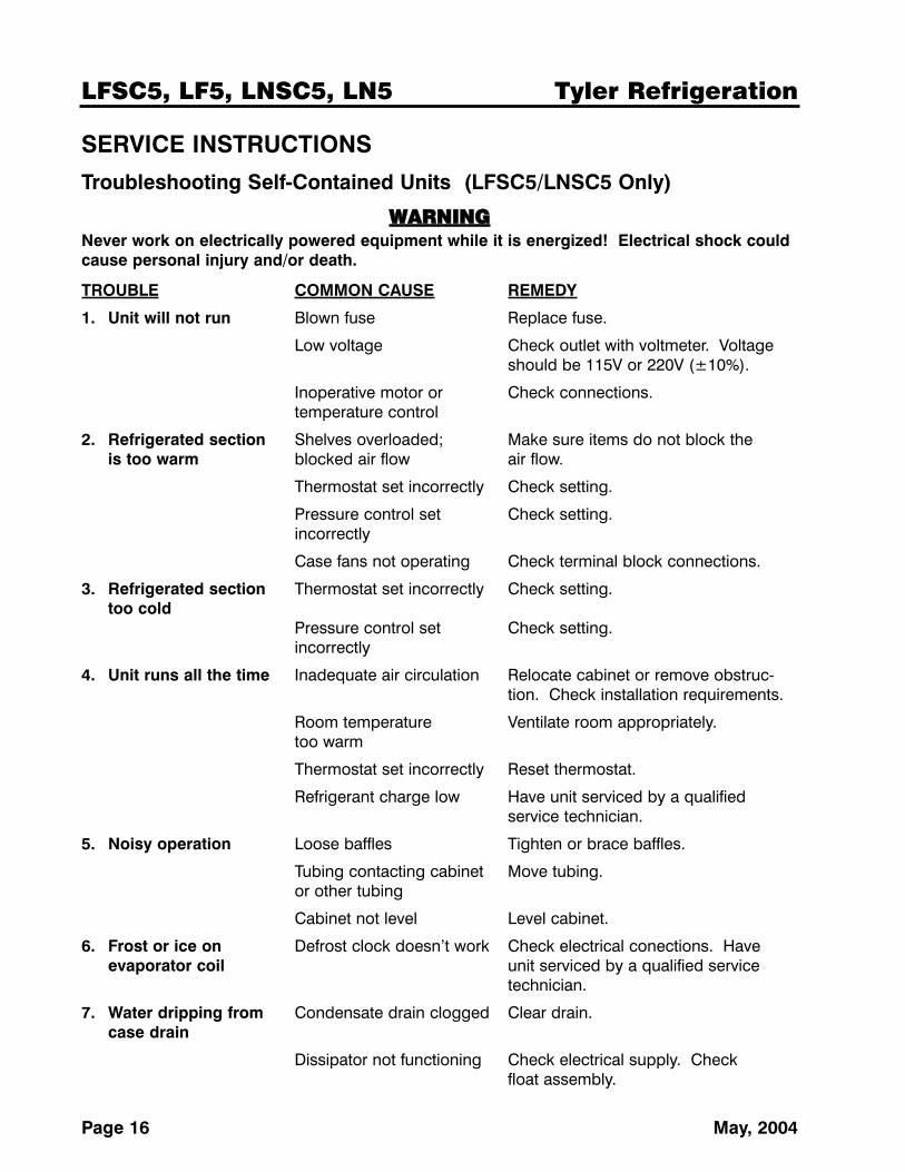
SERVICE INSTRUCTIONS
Troubleshooting Self-Contained Units (LFSC5/LNSC5 Only)
WWAARRNNIINNGGNever work on electrically powered equipment while it is energized! Electrical shock couldcause personal injury and/or death.
TROUBLE COMMON CAUSE REMEDY
1. Unit will not run Blown fuse Replace fuse.
Low voltage Check outlet with voltmeter. Voltage should be 115V or 220V (±10%).
Inoperative motor or Check connections.temperature control
2. Refrigerated section Shelves overloaded; Make sure items do not block the is too warm blocked air flow air flow.
Thermostat set incorrectly Check setting.
Pressure control set Check setting.incorrectly
Case fans not operating Check terminal block connections.
3. Refrigerated section Thermostat set incorrectly Check setting.too cold
Pressure control set Check setting.incorrectly
4. Unit runs all the time Inadequate air circulation Relocate cabinet or remove obstruc-tion. Check installation requirements.
Room temperature Ventilate room appropriately.too warm
Thermostat set incorrectly Reset thermostat.
Refrigerant charge low Have unit serviced by a qualified service technician.
5. Noisy operation Loose baffles Tighten or brace baffles.
Tubing contacting cabinet Move tubing.or other tubing
Cabinet not level Level cabinet.
6. Frost or ice on Defrost clock doesn’t work Check electrical conections. Have evaporator coil unit serviced by a qualified service
technician.
7. Water dripping from Condensate drain clogged Clear drain.case drain
Dissipator not functioning Check electrical supply. Check float assembly.
Installation & Service Manual LFSC5, LF5, LNSC5, LN5
May, 2004 Page 17
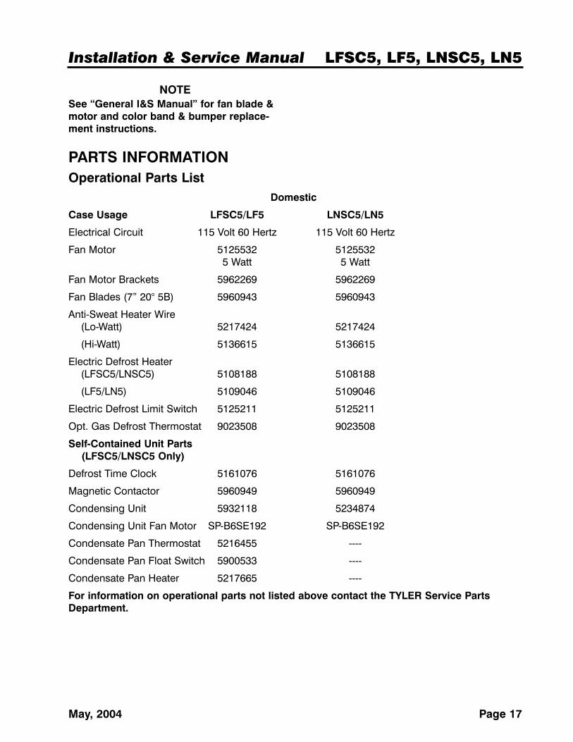
NOTESee “General I&S Manual” for fan blade &motor and color band & bumper replace-ment instructions.
PARTS INFORMATIONOperational Parts List
Domestic
Case Usage LFSC5/LF5 LNSC5/LN5
Electrical Circuit 115 Volt 60 Hertz 115 Volt 60 Hertz
Fan Motor 5125532 51255325 Watt 5 Watt
Fan Motor Brackets 5962269 5962269
Fan Blades (7” 20° 5B) 5960943 5960943
Anti-Sweat Heater Wire(Lo-Watt) 5217424 5217424
(Hi-Watt) 5136615 5136615
Electric Defrost Heater(LFSC5/LNSC5) 5108188 5108188
(LF5/LN5) 5109046 5109046
Electric Defrost Limit Switch 5125211 5125211
Opt. Gas Defrost Thermostat 9023508 9023508
Self-Contained Unit Parts(LFSC5/LNSC5 Only)
Defrost Time Clock 5161076 5161076
Magnetic Contactor 5960949 5960949
Condensing Unit 5932118 5234874
Condensing Unit Fan Motor SP-B6SE192 SP-B6SE192
Condensate Pan Thermostat 5216455 ----
Condensate Pan Float Switch 5900533 ----
Condensate Pan Heater 5217665 ----
For information on operational parts not listed above contact the TYLER Service PartsDepartment.
LFSC5, LF5, LNSC5, LN5 Tyler Refrigeration
Page 18 May, 2004
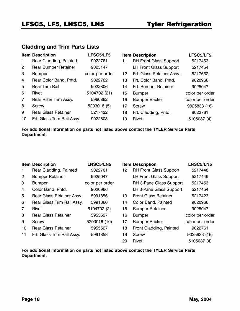
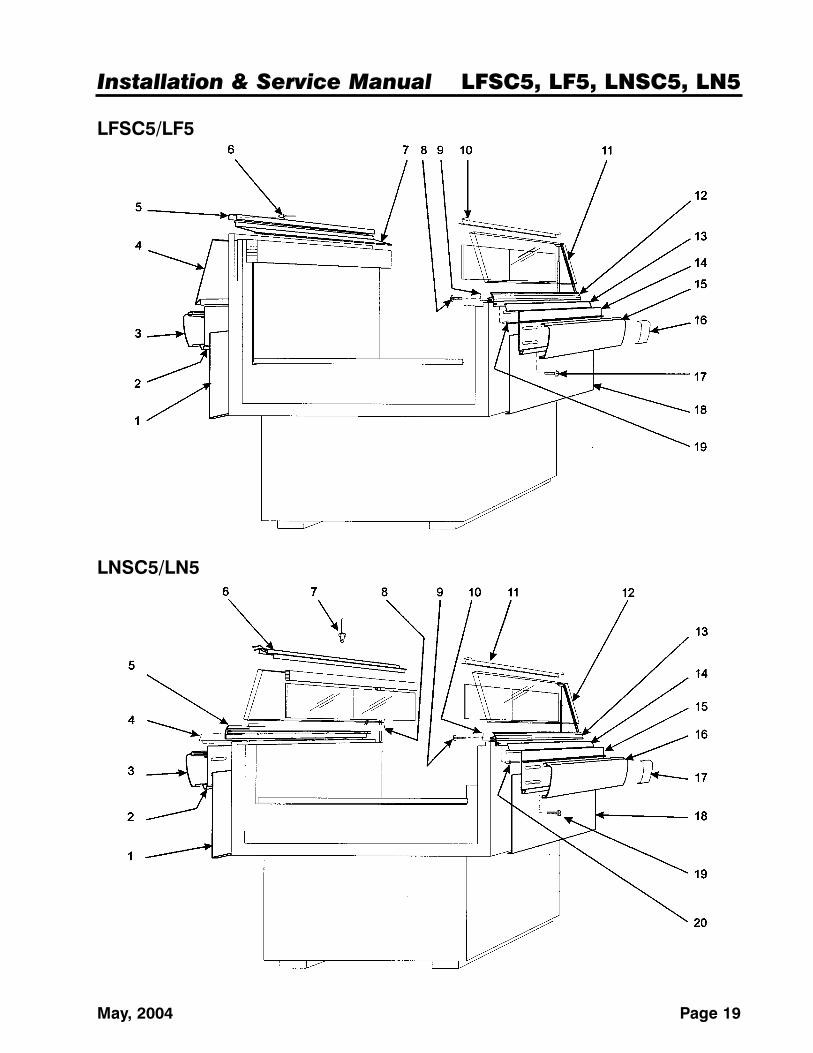
Cladding and Trim Parts ListsItem Description LFSC5/LF51 Rear Cladding, Painted 90227612 Rear Bumper Retainer 90251473 Bumper color per order4 Rear Color Band, Pntd. 90227625 Rear Trim Rail 90228066 Rivet 5104702 (21)7 Rear Riser Trim Assy. 59608628 Screw 5203018 (5)9 Rear Glass Retainer 521742210 Frt. Glass Trim Rail Assy. 9022803
Item Description LFSC5/LF511 RH Front Glass Support 5217453
LH Front Glass Support 521745412 Frt. Glass Retainer Assy. 521766213 Frt. Color Band, Pntd. 902096614 Frt. Bumper Retainer 902504715 Bumper color per order16 Bumper Backer color per order17 Screw 9025833 (16)18 Frt. Cladding, Pntd. 902276119 Rivet 5105037 (4)
For additional information on parts not listed above contact the TYLER Service PartsDepartment.
Item Description LNSC5/LN51 Rear Cladding, Painted 90227612 Bumper Retainer 90250473 Bumper color per order4 Color Band, Pntd. 90209665 Rear Glass Retainer Assy. 59918566 Rear Glass Trim Rail Assy. 59918607 Rivet 5104702 (2)8 Rear Glass Retainer 59555279 Screw 5203018 (10)10 Rear Glass Retainer 595552711 Frt. Glass Trim Rail Assy. 5991858
Item Description LNSC5/LN512 RH Front Glass Support 5217448
LH Front Glass Support 5217449RH 3-Pane Glass Support 5217453LH 3-Pane Glass Support 5217454
13 Front Glass Retainer 521742314 Color Band, Painted 902096615 Bumper Retainer 902504716 Bumper color per order17 Bumper Backer color per order18 Front Cladding, Painted 902276119 Screw 9025833 (16)20 Rivet 5105037 (4)
For additional information on parts not listed above contact the TYLER Service PartsDepartment.
Installation & Service Manual LFSC5, LF5, LNSC5, LN5