Manufacturer reserves the right to discontinue, or change at any time, specifications or designs without notice and without incurring obligations. Catalog No. 02-38HD0001-SI Printed in U.S.A. Form 38HD-4SI Pg 1 1-06 Replaces: 38HDC-3SI Book 1 4 Tab 3e 2f Installation, Start-Up and Service Instructions CONTENTS Page SAFETY CONSIDERATIONS ...................... 1 INSTALLATION ................................ 1-10 Step 1 — Complete Pre-Installation Checks ...... 1 • UNPACK UNIT • INSPECT SHIPMENT • CONSIDER SYSTEM REQUIREMENTS • MATCHING THE CONDENSING UNIT TO AN INDOOR UNIT Step 2 — Rig and Mount Unit ..................... 3 • MOUNTING ON GROUND • MOUNTING ON ROOF • RIGGING Step 3 — Complete Refrigerant Piping Connections ................................... 3 • CHECK ACCURATER CONTROL • FILTER DRIER • MAKE PIPING SWEAT CONNECTORS • PROVIDE SAFETY RELIEF Step 4 — Make Electrical Connections ........... 6 • CONTROL CIRCUIT WIRING • POWER WIRING • CONNECTIONS TO DUCT-FREE FAN COIL UNITS START-UP ....................................... 11 SERVICE ..................................... 11-14 MAINTENANCE ................................. 14 TROUBLESHOOTING..........................14,15 SAFETY CONSIDERATIONS Installing and servicing air conditioning equipment can be hazardous due to system pressure and electrical components. Only trained and qualified service personnel should install or service air conditioning equipment. Untrained personnel can perform basic maintenance, such as cleaning and replacing filters. All other operations should be performed by trained service personnel. When working on air conditioning equipment, observe safety precautions in litera- ture, tags, and labels attached to unit. Follow all safety codes. Wear safety glasses and work gloves. Use quenching cloth for brazing operations. Have fire extinguisher available. Read these instructions thoroughly . Consult local building codes and the National Electrical Code (NEC) for special installation requirements. INSTALLATION Step 1 — Complete Pre-Installation Checks UNPACK UNIT (See Fig. 1) — Move the unit to final loca- tion. Remove unit from carton, being careful not to damage service valves and grilles. INSPECT SHIPMENT — File a claim with the shipping company if shipment is damaged or incomplete. Check unit nameplate to ensure unit matches job requirements. CONSIDER SYSTEM REQUIREMENTS — Consult local building codes and NEC for special installation requirements. Allow sufficient space for airflow clearance, wiring, refrig- erant piping, and servicing unit. See Fig. 2. Locate unit so that condenser airflow is unrestricted on both sides. Refer to Fig. 2. Unit may be mounted on a level pad directly on base legs or mounted on raised pads at support points. See Fig. 2 for center of gravity. MATCHING THE CONDENSING UNIT TO AN INDOOR UNIT — The 38HDF,HDR units can be matched to a corresponding indoor unit. The 38HDF018-036 units can be matched with an in-ceiling cassette or high wall indoor unit. The 38HDR unit can be matched with under-ceiling and resi- dential fan coils. Refer to separate indoor unit literature for more information. Before installing or servicing system, always turn off main power to system. There may be more than one disconnect switch. Turn off accessory heater power if applicable. Elec- trical shock can cause serious personal injury. Puron® (R-410A) refrigerant systems operate at higher pressures than standard R-22 systems. Do not use R-22 ser- vice equipment or components on Puron refrigerant equip- ment. If service equipment is not rated for Puron refrigerant, equipment damage or personal injury may result. 38HDF018-036 Duct Free Condensing Units 38HDR018-060 Ducted Condensing Units Fig. 1 — 38HDF,HDR Unit
Transcript
Manufacturer reserves the right to discontinue, or change at any time, specifications or designs without notice and without incurring obligations.Catalog No. 02-38HD0001-SI Printed in U.S.A. Form 38HD-4SI Pg 1 1-06 Replaces: 38HDC-3SIBook 1 4
Installing and servicing air conditioning equipment can behazardous due to system pressure and electrical components.Only trained and qualified service personnel should install orservice air conditioning equipment.
Untrained personnel can perform basic maintenance, suchas cleaning and replacing filters. All other operations should beperformed by trained service personnel. When working on airconditioning equipment, observe safety precautions in litera-ture, tags, and labels attached to unit.
Follow all safety codes. Wear safety glasses and workgloves. Use quenching cloth for brazing operations. Have fireextinguisher available. Read these instructions thoroughly.Consult local building codes and the National Electrical Code(NEC) for special installation requirements.
INSTALLATION
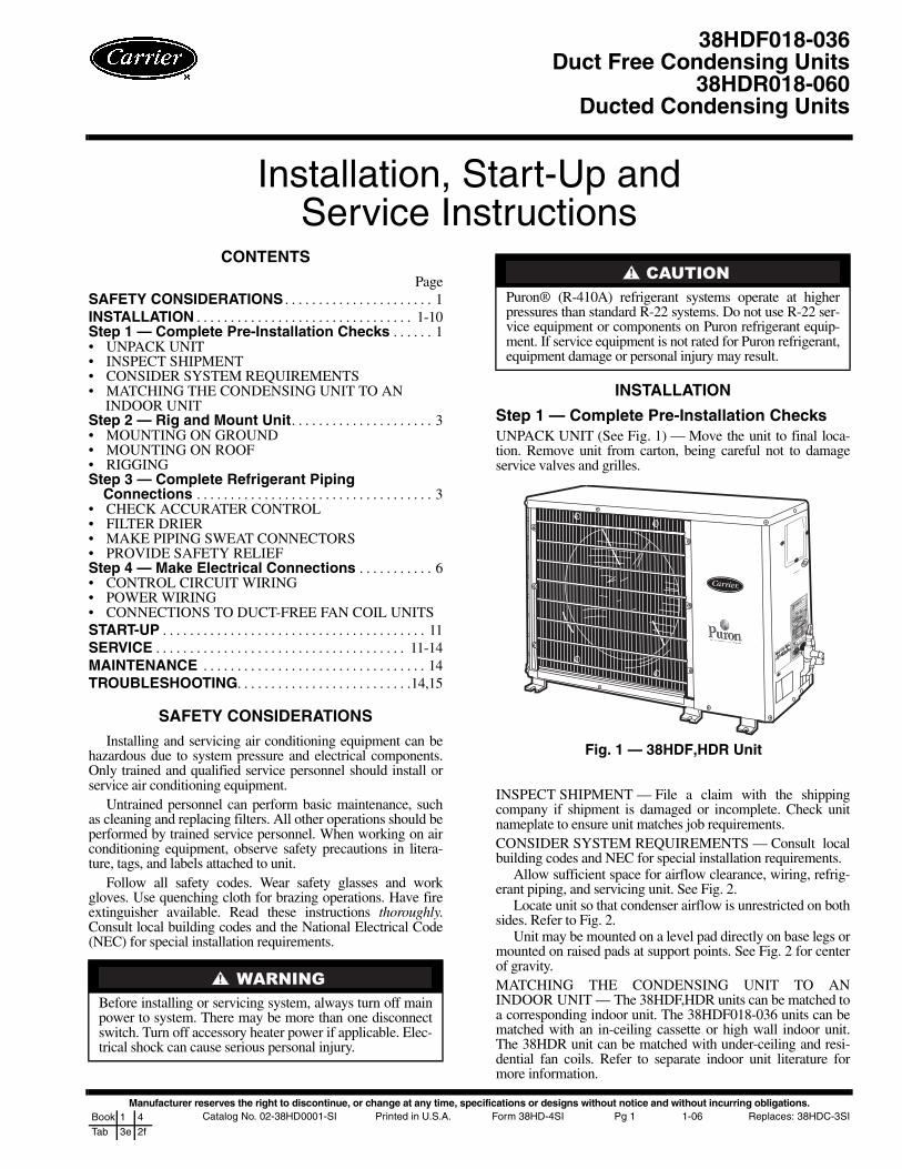
Step 1 — Complete Pre-Installation ChecksUNPACK UNIT (See Fig. 1) — Move the unit to final loca-tion. Remove unit from carton, being careful not to damageservice valves and grilles.
INSPECT SHIPMENT — File a claim with the shippingcompany if shipment is damaged or incomplete. Check unitnameplate to ensure unit matches job requirements.CONSIDER SYSTEM REQUIREMENTS — Consult localbuilding codes and NEC for special installation requirements.
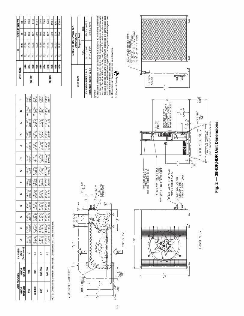
Allow sufficient space for airflow clearance, wiring, refrig-erant piping, and servicing unit. See Fig. 2.
Locate unit so that condenser airflow is unrestricted on bothsides. Refer to Fig. 2.
Unit may be mounted on a level pad directly on base legs ormounted on raised pads at support points. See Fig. 2 for centerof gravity.MATCHING THE CONDENSING UNIT TO ANINDOOR UNIT — The 38HDF,HDR units can be matched toa corresponding indoor unit. The 38HDF018-036 units can bematched with an in-ceiling cassette or high wall indoor unit.The 38HDR unit can be matched with under-ceiling and resi-dential fan coils. Refer to separate indoor unit literature formore information.
Before installing or servicing system, always turn off mainpower to system. There may be more than one disconnectswitch. Turn off accessory heater power if applicable. Elec-trical shock can cause serious personal injury.
Puron® (R-410A) refrigerant systems operate at higherpressures than standard R-22 systems. Do not use R-22 ser-vice equipment or components on Puron refrigerant equip-ment. If service equipment is not rated for Puron refrigerant,equipment damage or personal injury may result.
38HDF018-036Duct Free Condensing Units
38HDR018-060Ducted Condensing Units
Fig. 1 — 38HDF,HDR Unit
2
(FIE
LD P
RO
VID
ED
AN
D IN
STA
LLE
D)
Fig
.2—
38H
DF,
HD
RU
nit
Dim
ensi
on
s
NO
TE
:Dim
ensi
ons
show
nin
feet
-inch
es.D
imen
sion
sin
()
are
mill
imet
ers.
UN
ITM
OD
EL
SC
HA
SS
ISS
IZE
(Ref
eren
ce)
AB
CD
EF
GH
JK
LN
P38
HD
FU
nit
Siz
e38
HD
RU
nit
Siz
e
018
018
02′
-11 /
8″3′
-015
/ 16″
1′-2
9 /16
″1′
-4″
1′-1
17/ 1
6″1′
-53 /
16″
1′-5
1 /8″
1′-1
0″1′
-1″
0′-6
5 /8″
0′-1
11/ 4
″0′
-215
/ 16″
0′-6
″(6
38.2
)(9
38.2
)(3
69.9
)(4
06.4
)(5
95.3
)(4
36.6
)(4
35)
(559
.1)
(330
.2)
(168
.3)
(285
.8)
(75)
(152
.4)
024,
030
024
0.6
2′-7
1 /8″
3′-0
15/ 1
6″1′
-29 /
16″
1′-4
″1′
-117
/ 16″
1′-5
3 /16
″1′
-111
/ 8″
2′-4
″1′
-2″
0′-6
3 /4″
0′-1
15/ 8
″0′
-215
/ 16″
0′-6
″(7
90.6
)(9
38.2
)(3
69.9
)(4
06.4
)(5
95.3
)(4
36.6
)(5
87.4
)(7
11.5
)(3
55.6
)(1
71.5
)(2
95.3
)(7
5)(1
52.4
)
036
030,
036
1.0
3′-1
3 /16
″3′
-89 /
16″
1′-5
1 /16
″1′
-67 /
16″
2′-6
1 /2″
1′-7
5 /8″
2′-5
3 /16
″2′
-101
/ 16″
1′-1
11/ 1
6″0′
-81 /
8″1′
-37 /
8″0′
-37 /
16″
0′-6
1 /2″
(944
.6)
(113
1.9)
(433
.4)
(468
.3)
(774
.7)
(498
.5)
(741
)(8
65.5
)(3
47.7
)(2
06.4
)(4
03.2
)(8
8)(1
65.4
)
—04
8,06
01.
63′
-73 /
16″
3′-8
9 /16
″1′
-51 /
16″
1′-6
7 /16
″2′
-61 /
2″1′
-75 /
8″2′
-113
/ 16″
3′-4
1 /16
″1′
-21 /
2″0′
-81 /
2″1′
-67 /
8″0′
-37 /
16″
0′-6
1 /2″
(109
7)(1
131.
9)(4
33.4
)(4
68.3
)(7
74.7
)(4
98.5
)(8
93.4
)(1
017.
9)(3
54.2
)(2
15.9
)(4
79.4
)(8
8)(1
65.4
)
UN
ITS
IZE
MO
PE
RA
TIN
GW
T
in.
mm
lbkg
38H
DF
018
5 /8
15.8
816
675
.3
024
5 /8
15.8
817
679
.8
030
3 /4
19.0
518
784
.8
036
3 /4
19.0
525
011
3.4
38H
DR
018
5 /8
15.8
816
675
.8
024
5 /8
15.8
817
679
.8
030
3 /4
19.0
518
784
.8
036
3 /4
19.0
525
011
3.4
048
7 /8
22.2
227
812
6.1
060
7 /8
22.2
230
613
8.8
NO
TE
S:
1.R
equi
red
clea
ranc
es:
with
coil
faci
ngw
all,
allo
w6
in.
min
imum
clea
ranc
eon
coil
side
and
coil
end,
and
3fe
etm
inim
umcl
eara
nce
onco
mpr
esso
ren
dan
dfa
nsi
de.
With
fan
faci
ngw
all,
allo
w8
in.
min
imum
clea
ranc
eon
fan
side
and
coil
end,
and
3fe
etm
inim
umcl
eara
nce
onco
mpr
esso
ren
dan
dco
ilsi
de.W
ithm
ulti-
unit
appl
icat
ion,
arra
nge
units
sodi
scha
rge
ofon
edo
esno
tent
erin
leto
fano
ther
.2.
Dim
ensi
ons
inpa
rent
hesi
sar
ein
mill
imet
ers.
3.C
ente
rof
Gra
vity
.
UN
ITS
IZE
MIN
IMU
MM
OU
NT
ING
PAD
DIM
EN
SIO
NS
Su
pp
ort
Fee
t
ft-i
n.
mm
CH
AS
SIS
SIZ
ES
0&
.61′
-11″
x3′
-6″
584.
2x
1066
.8
CH
AS
SIS
SIZ
ES
1&
1.6
2′-0
″x
4′-2
″60
9.6
x12
70
3
Step 2 — Rig and Mount UnitMOUNTING ON GROUND — Mount unit on a solid, levelconcrete pad. Position unit so water or ice from roof does notfall directly onto unit. Accessory stacking kits can be usedwhen units are to be stacked. See installation instructionsprovided with the accessory kit. Use field-provided snow standor ice rack where prolonged subfreezing temperatures or heavysnow occurs.
If conditions or local codes require unit be fastened to a pad,6 field-supplied tiedown bolts should be used and fastenedthrough slots provided in unit mounting feet.MOUNTING ON ROOF — Mount unit on a level platformor frame at least 6 in. above roof surface. Isolate unit and tub-ing from structure.RIGGING
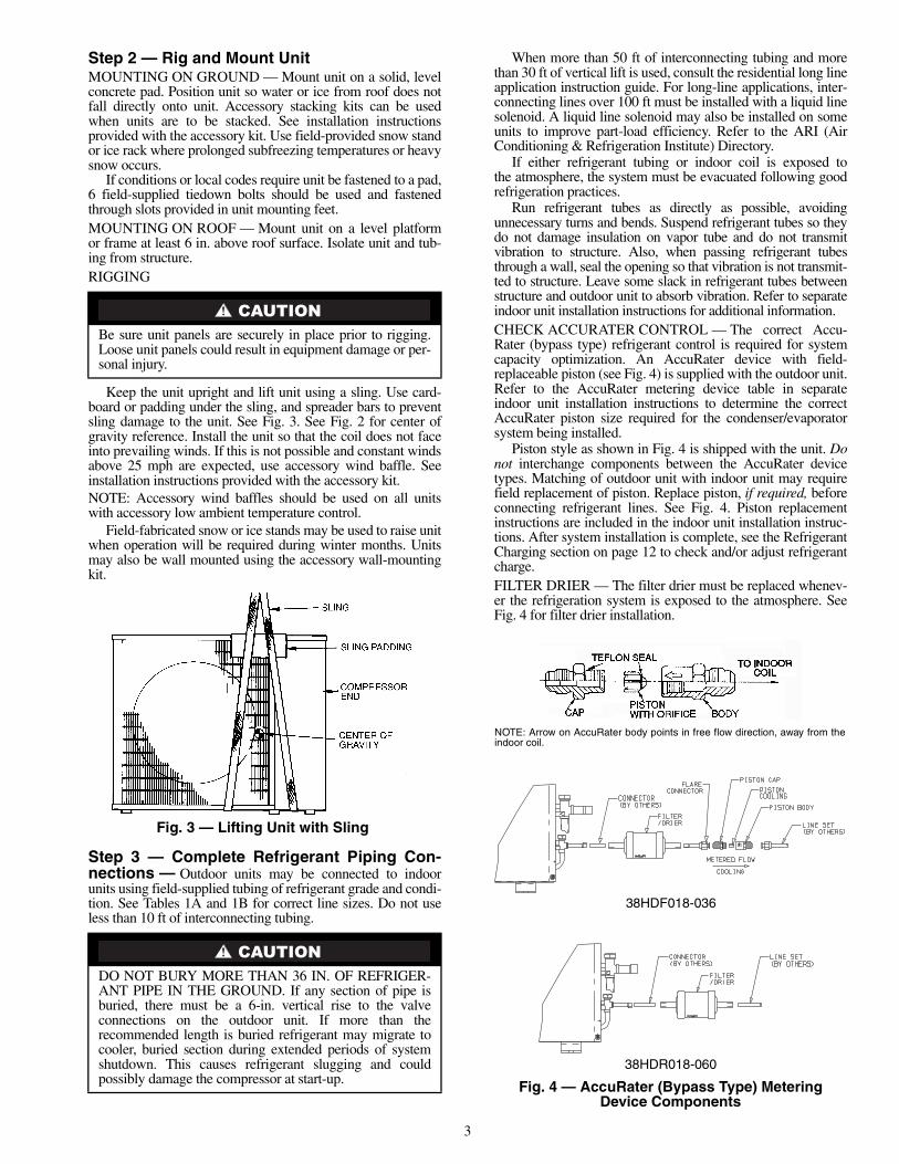
Keep the unit upright and lift unit using a sling. Use card-board or padding under the sling, and spreader bars to preventsling damage to the unit. See Fig. 3. See Fig. 2 for center ofgravity reference. Install the unit so that the coil does not faceinto prevailing winds. If this is not possible and constant windsabove 25 mph are expected, use accessory wind baffle. Seeinstallation instructions provided with the accessory kit.NOTE: Accessory wind baffles should be used on all unitswith accessory low ambient temperature control.
Field-fabricated snow or ice stands may be used to raise unitwhen operation will be required during winter months. Unitsmay also be wall mounted using the accessory wall-mountingkit.
Step 3 — Complete Refrigerant Piping Con-nections — Outdoor units may be connected to indoorunits using field-supplied tubing of refrigerant grade and condi-tion. See Tables 1A and 1B for correct line sizes. Do not useless than 10 ft of interconnecting tubing.
When more than 50 ft of interconnecting tubing and morethan 30 ft of vertical lift is used, consult the residential long lineapplication instruction guide. For long-line applications, inter-connecting lines over 100 ft must be installed with a liquid linesolenoid. A liquid line solenoid may also be installed on someunits to improve part-load efficiency. Refer to the ARI (AirConditioning & Refrigeration Institute) Directory.
If either refrigerant tubing or indoor coil is exposed tothe atmosphere, the system must be evacuated following goodrefrigeration practices.
Run refrigerant tubes as directly as possible, avoidingunnecessary turns and bends. Suspend refrigerant tubes so theydo not damage insulation on vapor tube and do not transmitvibration to structure. Also, when passing refrigerant tubesthrough a wall, seal the opening so that vibration is not transmit-ted to structure. Leave some slack in refrigerant tubes betweenstructure and outdoor unit to absorb vibration. Refer to separateindoor unit installation instructions for additional information.CHECK ACCURATER CONTROL — The correct Accu-Rater (bypass type) refrigerant control is required for systemcapacity optimization. An AccuRater device with field-replaceable piston (see Fig. 4) is supplied with the outdoor unit.Refer to the AccuRater metering device table in separateindoor unit installation instructions to determine the correctAccuRater piston size required for the condenser/evaporatorsystem being installed.
Piston style as shown in Fig. 4 is shipped with the unit. Donot interchange components between the AccuRater devicetypes. Matching of outdoor unit with indoor unit may requirefield replacement of piston. Replace piston, if required, beforeconnecting refrigerant lines. See Fig. 4. Piston replacementinstructions are included in the indoor unit installation instruc-tions. After system installation is complete, see the RefrigerantCharging section on page 12 to check and/or adjust refrigerantcharge.FILTER DRIER — The filter drier must be replaced whenev-er the refrigeration system is exposed to the atmosphere. SeeFig. 4 for filter drier installation.
Be sure unit panels are securely in place prior to rigging.Loose unit panels could result in equipment damage or per-sonal injury.
DO NOT BURY MORE THAN 36 IN. OF REFRIGER-ANT PIPE IN THE GROUND. If any section of pipe isburied, there must be a 6-in. vertical rise to the valveconnections on the outdoor unit. If more than therecommended length is buried refrigerant may migrate tocooler, buried section during extended periods of systemshutdown. This causes refrigerant slugging and couldpossibly damage the compressor at start-up.
Fig. 3 — Lifting Unit with Sling
NOTE: Arrow on AccuRater body points in free flow direction, away from theindoor coil.
Only use factory specified liquid-line filter driers with ratedworking pressures less than 600 psig.NOTE: Do not install a suction-line filter drier in liquid line.MAKE PIPING SWEAT CONNECTIONS — Remove plasticcaps from liquid and suction service valves. Use refrigerantgrade tubing. Service valves are closed from the factory and areready for brazing. After wrapping the service valve with a wetcloth, the tubing set can be brazed to the service valve using ei-ther silver bearing or non-silver bearing brazing material. Con-sult local code requirements. Refrigerant tubing and the indoorcoil are now ready for leak testing.NOTE: Unit is shipped with R-410A factory charge indicatedon nameplate.
Pass nitrogen or other inert gas through piping while braz-ing to prevent formation of copper oxide.
PROVIDE SAFETY RELIEF — A fusible plug is located inunit suction line; do not cap this plug. If local code requiresadditional safety devices, install as directed.
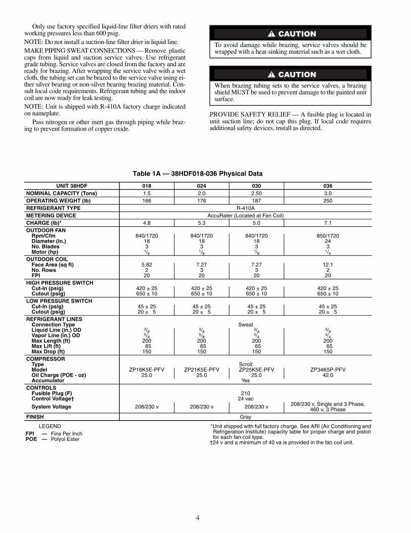
Table 1A — 38HDF018-036 Physical Data
LEGEND *Unit shipped with full factory charge. See ARI (Air Conditioning andRefrigeration Institute) capacity table for proper charge and pistonfor each fan coil type.
†24 v and a minimum of 40 va is provided in the fan coil unit.
To avoid damage while brazing, service valves should bewrapped with a heat-sinking material such as a wet cloth.
When brazing tubing sets to the service valves, a brazingshield MUST be used to prevent damage to the painted unitsurface.
UNIT 38HDF 018 024 030 036NOMINAL CAPACITY (Tons) 1.5 2.0 2.50 3.0OPERATING WEIGHT (lb) 166 176 187 250REFRIGERANT TYPE R-410AMETERING DEVICE AccuRater (Located at Fan Coil)CHARGE (lb)* 4.8 5.3 5.0 7.1OUTDOOR FAN
System Voltage 208/230 v 208/230 v 208/230 v 208/230 v, Single and 3 Phase,460 v, 3 Phase
FINISH Gray
FPI — Fins Per InchPOE — Polyol Ester
5
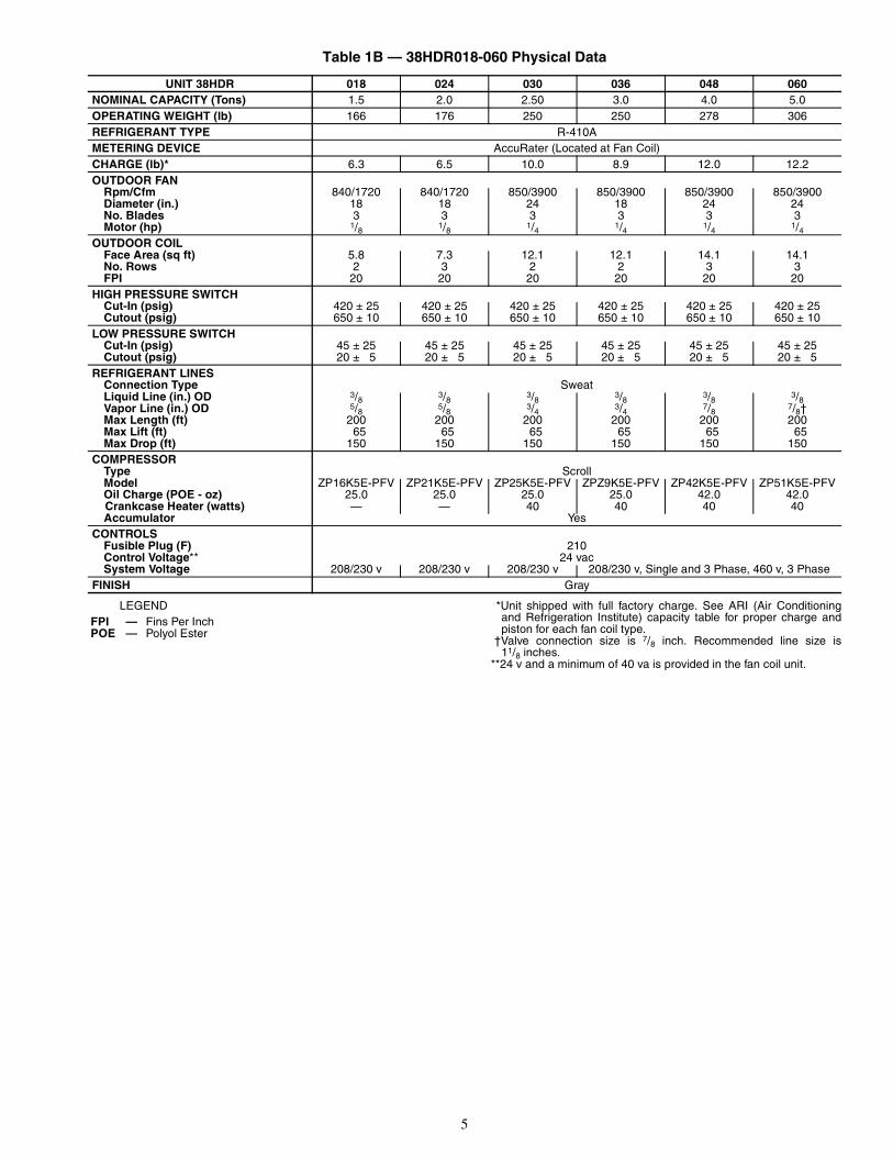
Table 1B — 38HDR018-060 Physical Data
LEGEND *Unit shipped with full factory charge. See ARI (Air Conditioningand Refrigeration Institute) capacity table for proper charge andpiston for each fan coil type.
†Valve connection size is 7/8 inch. Recommended line size is11/8 inches.
**24 v and a minimum of 40 va is provided in the fan coil unit.
UNIT 38HDR 018 024 030 036 048 060NOMINAL CAPACITY (Tons) 1.5 2.0 2.50 3.0 4.0 5.0OPERATING WEIGHT (lb) 166 176 250 250 278 306REFRIGERANT TYPE R-410AMETERING DEVICE AccuRater (Located at Fan Coil)CHARGE (lb)* 6.3 6.5 10.0 8.9 12.0 12.2OUTDOOR FAN
CONTROLSFusible Plug (F) 210Control Voltage** 24 vacSystem Voltage 208/230 v 208/230 v 208/230 v 208/230 v, Single and 3 Phase, 460 v, 3 Phase
FINISH Gray
FPI — Fins Per InchPOE — Polyol Ester
6
Step 4 — Make Electrical Connections
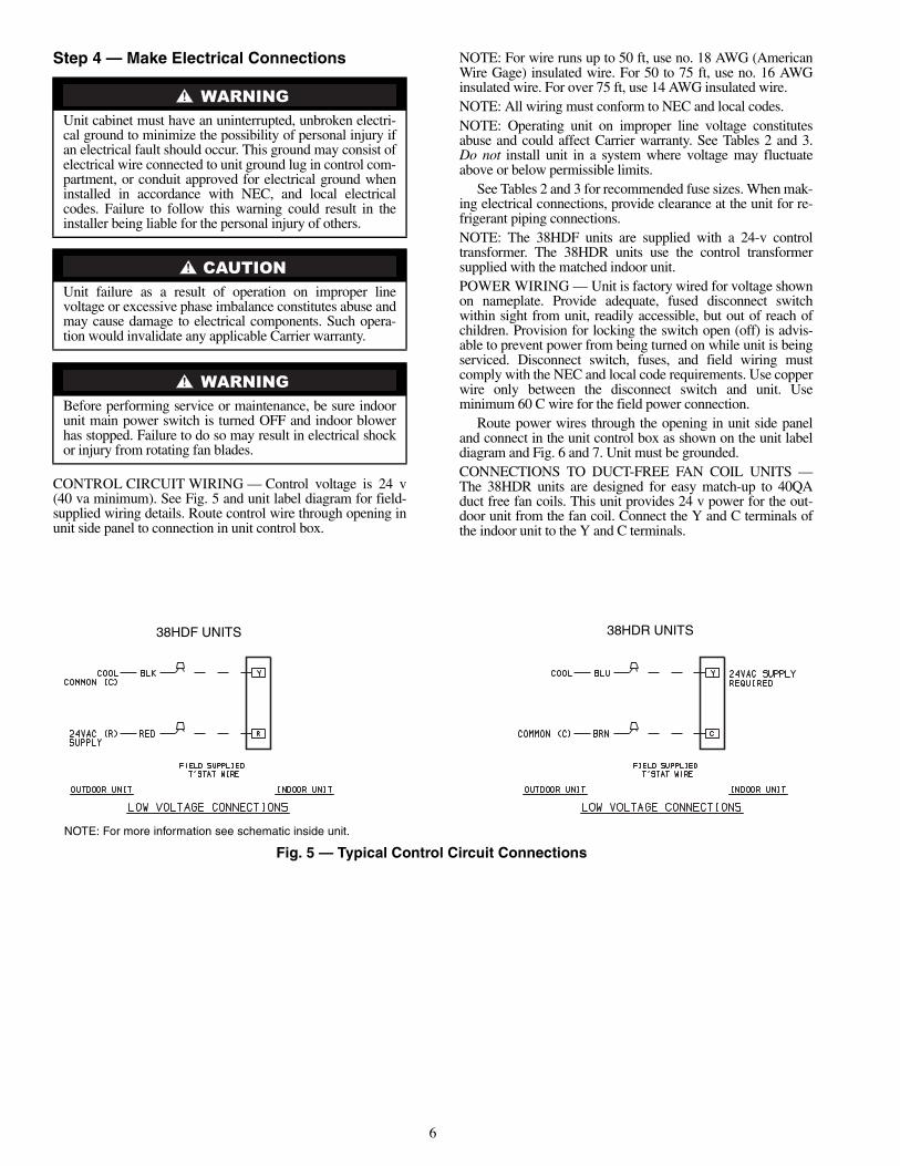
CONTROL CIRCUIT WIRING — Control voltage is 24 v(40 va minimum). See Fig. 5 and unit label diagram for field-supplied wiring details. Route control wire through opening inunit side panel to connection in unit control box.
NOTE: For wire runs up to 50 ft, use no. 18 AWG (AmericanWire Gage) insulated wire. For 50 to 75 ft, use no. 16 AWGinsulated wire. For over 75 ft, use 14 AWG insulated wire.NOTE: All wiring must conform to NEC and local codes.NOTE: Operating unit on improper line voltage constitutesabuse and could affect Carrier warranty. See Tables 2 and 3.Do not install unit in a system where voltage may fluctuateabove or below permissible limits.
See Tables 2 and 3 for recommended fuse sizes. When mak-ing electrical connections, provide clearance at the unit for re-frigerant piping connections.NOTE: The 38HDF units are supplied with a 24-v controltransformer. The 38HDR units use the control transformersupplied with the matched indoor unit.POWER WIRING — Unit is factory wired for voltage shownon nameplate. Provide adequate, fused disconnect switchwithin sight from unit, readily accessible, but out of reach ofchildren. Provision for locking the switch open (off) is advis-able to prevent power from being turned on while unit is beingserviced. Disconnect switch, fuses, and field wiring mustcomply with the NEC and local code requirements. Use copperwire only between the disconnect switch and unit. Useminimum 60 C wire for the field power connection.
Route power wires through the opening in unit side paneland connect in the unit control box as shown on the unit labeldiagram and Fig. 6 and 7. Unit must be grounded.CONNECTIONS TO DUCT-FREE FAN COIL UNITS —The 38HDR units are designed for easy match-up to 40QAduct free fan coils. This unit provides 24 v power for the out-door unit from the fan coil. Connect the Y and C terminals ofthe indoor unit to the Y and C terminals.
Unit cabinet must have an uninterrupted, unbroken electri-cal ground to minimize the possibility of personal injury ifan electrical fault should occur. This ground may consist ofelectrical wire connected to unit ground lug in control com-partment, or conduit approved for electrical ground wheninstalled in accordance with NEC, and local electricalcodes. Failure to follow this warning could result in theinstaller being liable for the personal injury of others.
Unit failure as a result of operation on improper linevoltage or excessive phase imbalance constitutes abuse andmay cause damage to electrical components. Such opera-tion would invalidate any applicable Carrier warranty.
Before performing service or maintenance, be sure indoorunit main power switch is turned OFF and indoor blowerhas stopped. Failure to do so may result in electrical shockor injury from rotating fan blades.
38HDF UNITS 38HDR UNITS
NOTE: For more information see schematic inside unit.
Fig. 5 — Typical Control Circuit Connections
7
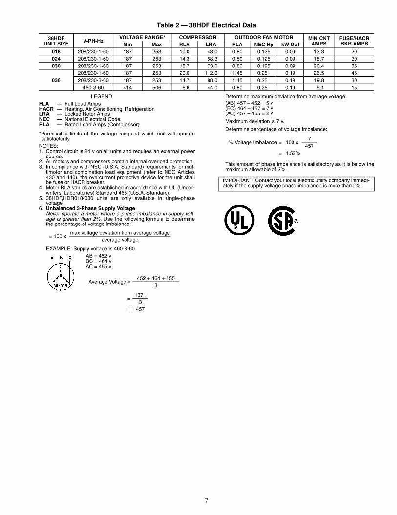
Table 2 — 38HDF Electrical Data
LEGEND
*Permissible limits of the voltage range at which unit will operatesatisfactorily.
NOTES:1. Control circuit is 24 v on all units and requires an external power
source.2. All motors and compressors contain internal overload protection.3. In compliance with NEC (U.S.A. Standard) requirements for mul-
timotor and combination load equipment (refer to NEC Articles430 and 440), the overcurrent protective device for the unit shallbe fuse or HACR breaker.
4. Motor RLA values are established in accordance with UL (Under-writers’ Laboratories) Standard 465 (U.S.A. Standard).
5. 38HDF,HDR018-030 units are only available in single-phasevoltage.
6. Unbalanced 3-Phase Supply VoltageNever operate a motor where a phase imbalance in supply volt-age is greater than 2%. Use the following formula to determinethe percentage of voltage imbalance:
EXAMPLE: Supply voltage is 460-3-60.AB = 452 vBC = 464 vAC = 455 v
Determine maximum deviation from average voltage:(AB) 457 – 452 = 5 v(BC) 464 – 457 = 7 v(AC) 457 – 455 = 2 v
Maximum deviation is 7 v.
Determine percentage of voltage imbalance:
This amount of phase imbalance is satisfactory as it is below themaximum allowable of 2%.
38HDFUNIT SIZE V-PH-Hz
VOLTAGE RANGE* COMPRESSOR OUTDOOR FAN MOTOR MIN CKTAMPS
FUSE/HACRBKR AMPSMin Max RLA LRA FLA NEC Hp kW Out
FLA — Full Load AmpsHACR — Heating, Air Conditioning, RefrigerationLRA — Locked Rotor AmpsNEC — National Electrical CodeRLA — Rated Load Amps (Compressor)
= 100 xmax voltage deviation from average voltage
average voltage
Average Voltage =452 + 464 + 455
3
=1371
3= 457
% Voltage Imbalance = 100 x7
457= 1.53%
IMPORTANT: Contact your local electric utility company immedi-ately if the supply voltage phase imbalance is more than 2%.
8
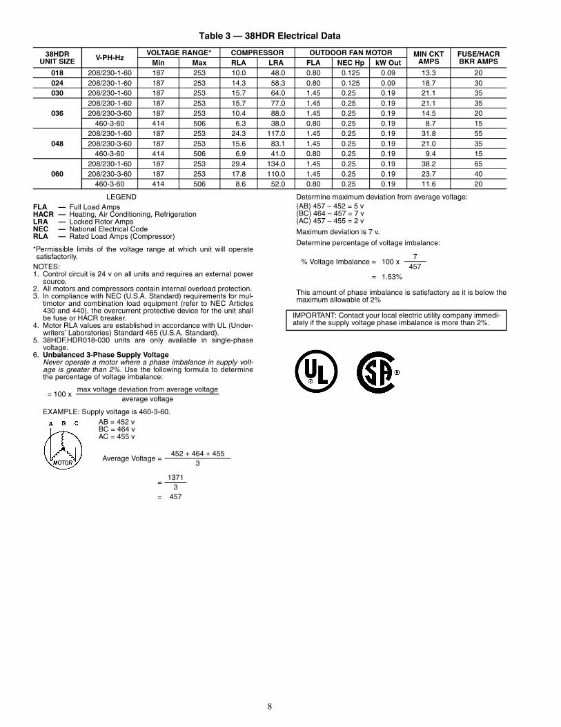
Table 3 — 38HDR Electrical Data
LEGEND
*Permissible limits of the voltage range at which unit will operatesatisfactorily.
NOTES:1. Control circuit is 24 v on all units and requires an external power
source.2. All motors and compressors contain internal overload protection.3. In compliance with NEC (U.S.A. Standard) requirements for mul-
timotor and combination load equipment (refer to NEC Articles430 and 440), the overcurrent protective device for the unit shallbe fuse or HACR breaker.
4. Motor RLA values are established in accordance with UL (Under-writers’ Laboratories) Standard 465 (U.S.A. Standard).
5. 38HDF,HDR018-030 units are only available in single-phasevoltage.
6. Unbalanced 3-Phase Supply VoltageNever operate a motor where a phase imbalance in supply volt-age is greater than 2%. Use the following formula to determinethe percentage of voltage imbalance:
EXAMPLE: Supply voltage is 460-3-60.AB = 452 vBC = 464 vAC = 455 v
Determine maximum deviation from average voltage:(AB) 457 – 452 = 5 v(BC) 464 – 457 = 7 v(AC) 457 – 455 = 2 v
Maximum deviation is 7 v.
Determine percentage of voltage imbalance:
This amount of phase imbalance is satisfactory as it is below themaximum allowable of 2%
38HDRUNIT SIZE V-PH-Hz
VOLTAGE RANGE* COMPRESSOR OUTDOOR FAN MOTOR MIN CKTAMPS
FUSE/HACRBKR AMPSMin Max RLA LRA FLA NEC Hp kW Out
FLA — Full Load AmpsHACR — Heating, Air Conditioning, RefrigerationLRA — Locked Rotor AmpsNEC — National Electrical CodeRLA — Rated Load Amps (Compressor)
= 100 xmax voltage deviation from average voltage
average voltage
Average Voltage =452 + 464 + 455
3
=1371
3= 457
% Voltage Imbalance = 100 x7
457= 1.53%
IMPORTANT: Contact your local electric utility company immedi-ately if the supply voltage phase imbalance is more than 2%.
9
LEG
EN
D
NO
TE
S:
1.C
ompr
esso
ran
dfa
nm
otor
sar
eth
erm
ally
prot
ecte
d.2.
Wire
inac
cord
ance
with
Nat
iona
lEle
ctric
alC
ode
(NE
C)
and
loca
lcod
es.
Rep
lace
any
orig
inal
wire
sw
ith90
°C
wire
orits
equi
vale
nt.
3.U
sem
inim
um60
°C
wire
for
field
pow
erw
iring
.4.
Tran
sfor
mer
has
inte
rnal
4.5A
ther
mal
fuse
onth
epr
imar
ysi
de.
5.Tr
ansf
orm
erfa
ctor
yw
ired
for
230
v.F
or20
8v
mov
ebl
ack
wire
to20
8vo
ltta
pon
tran
sfor
mer
.6.
Cra
nkca
sehe
ater
and
ther
mos
tatu
sed
onse
lect
edm
odel
son
ly.
C—
Con
tact
or,C
ompr
esso
rC
AP
—C
apac
itor
CC
HT
—C
rank
case
Hea
ter
The
rmos
tat
CH
—C
rank
case
Hea
ter
CO
MP
—C
ompr
esso
rM
otor
EQ
UIP
—E
quip
men
tG
ND
—G
roun
dH
PS
—H
igh-
Pre
ssur
eS
witc
hL
PS
—Lo
w-P
ress
ure
Sw
itch
OF
M—
Out
door
-Fan
Mot
orO
L—
Ove
rload
TB
—Te
rmin
alB
oard
TR
AN
—Tr
ansf
orm
er
Spl
ice
(Fie
ld)
Term
inal
(Mar
ked)
Term
inal
(Unm
arke
d)
Term
inal
Blo
ck
Spl
ice
Fact
ory
Wiri
ngF
ield
Con
trol
Wiri
ngF
ield
Pow
erW
iring
Opt
iona
lor
Acc
esso
ryW
ire
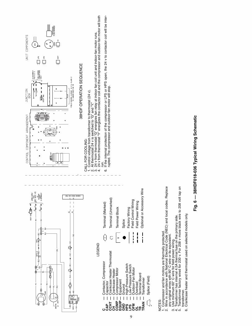
Fig
.6—
38H
DF
018-
036
Typ
ical
Wir
ing
Sch
emat
ic38H
DF
OP
ER
ATIO
NS
EQ
UE
NC
EC
ALL
FO
RC
OO
LIN
G:
1.C
ontr
olvo
ltage
from
tran
sfor
mer
toth
erm
osta
t(24
v).
2.A
tthe
rmos
tat2
4v
issw
itche
dto
“G”
and
“Y.”
3.24
vfr
omth
erm
osta
t“G
”en
ergi
zes
fan
rela
yat
indo
orfa
nco
ilun
itan
din
door
-fan
mot
orru
ns.
4.24
vfr
omth
erm
osta
t“Y
”en
ergi
zes
the
cont
acto
rco
ilan
dth
eco
mpr
esso
ran
dou
tdoo
r-fa
nm
otor
will
both
run.
6.If
the
inte
rnal
prot
ectio
nof
the
com
pres
sor
orLP
Sor
HP
Sop
en,
the
24v
toco
ntac
tor
coil
will
bein
ter-
rupt
ed.T
heco
mpr
esso
ran
dou
tdoo
r-fa
nm
otor
will
stop
.
10
LEG
EN
D
NO
TE
S:
1.C
ompr
esso
ran
dfa
nm
otor
sar
eth
erm
ally
prot
ecte
d.2.
Wire
inac
cord
ance
with
Nat
iona
lEle
ctric
alC
ode
(NE
C)
and
loca
lcod
es.R
epla
cean
yor
igin
alw
ires
with
90°
Cw
ireor
itseq
uiva
lent
.3.
The
CLO
lock
sou
tth
eC
OM
Pto
prev
ent
shor
tcy
clin
gon
CO
MP
over
load
san
dsa
fety
devi
ces.
Bef
ore
repl
acin
gC
LOch
eck
thes
ede
vice
s.4.
Ifin
door
sect
ion
has
atr
ansf
orm
erw
itha
grou
nded
seco
ndar
y,co
nnec
tth
egr
ound
edsi
deto
“C”
onth
elo
wvo
ltage
boar
d.5.
Use
min
imum
60°
Cw
irefo
rfie
ldpo
wer
wiri
ng.
6.C
rank
case
heat
eran
dth
erm
osta
tuse
don
sele
cted
mod
els
only
.
C—
Con
tact
or,C
ompr
esso
rC
AP
—C
apac
itor
CC
HT
—C
rank
case
Hea
ter
The
rmos
tat
CH
—C
rank
case
Hea
ter
CL
O—
Com
pres
sor
Lock
out
CO
MP
—C
ompr
esso
rM
otor
CT
—C
urre
ntTr
ansf
orm
erE
QU
IP—
Equ
ipm
ent
GN
D—
Gro
und
HP
S—
Hig
h-P
ress
ure
Sw
itch
LP
S—
Low
-Pre
ssur
eS
witc
hO
FM
—O
utdo
or-F
anM
otor
OL
—O
verlo
adT
B—
Term
inal
Boa
rd
Spl
ice
(Fie
ld)
Term
inal
(Mar
ked)
Term
inal
(Unm
arke
d)
Term
inal
Blo
ck
Spl
ice
Fact
ory
Wiri
ngF
ield
Con
trol
Wiri
ngF
ield
Pow
erW
iring
38H
DR
OP
ER
ATIO
NS
EQ
UE
NC
EC
ALL
FO
RC
OO
LIN
G:
1.C
ontr
olvo
ltage
from
tran
sfor
mer
toth
erm
osta
t(24
v).
2.A
tthe
rmos
tat2
4v
issw
itche
dto
“G”
and
“Y.”
3.24
vfr
omth
erm
osta
t“G
”en
ergi
zes
fan
rela
yat
indo
orfa
nco
ilan
din
door
-fan
mot
orru
ns.
4.24
vfr
omth
erm
osta
t“Y
”en
ergi
zes
the
logi
cin
the
CLO
,an
dth
eco
ntac
tor
coil,
both
atth
eou
tdoo
run
it.C
ompr
esso
ran
dou
tdoo
r-fa
nm
otor
run.
6.If
the
inte
rnal
prot
ecto
rof
the
com
pres
sor,
HP
S,
orLP
Sop
en,
the
24v
toth
eco
ntac
tor
coil
will
bein
ter-
rupt
ed,
the
com
pres
sor
and
outd
oor-
fan
mot
orw
illst
op,
and
the
CLO
will
keep
the
circ
uit
open
until
rese
tby
stop
ping
and
rest
artin
gth
e24
vpo
wer
atth
eth
erm
osta
t.
Fig
.7—
38H
DR
018-
060
Typ
ical
Wir
ing
Sch
emat
ic
11
START-UPPreliminary Checks
1. Check that all internal wiring connections are tight andthat all barriers, covers, and panels are in place.
2. Field electrical power source must agree with unit name-plate rating.
3. All service valves must be open.4. Belly-band crankcase heater must be tight on compressor
crankcase for those units with belly-band heaters.
Leak Test — Field piping and fan coil must be leak testedby pressure method. Use R-410A at approximately 25 psigbacked up with an inert gas to a total pressure not to exceed245 psig.
Leak detectors should be designed to detect HFC (hydro-fluorocarbon) refrigerant.
Evacuate and Dehydrate — Field piping and fan coilmust be evacuated and dehydrated.
Charge System — Release charge into system by open-ing (backseating) liquid and suction line service valves. Referto separate indoor unit installation instructions for the requiredtotal system charge when connected to 25 ft of tubing.
To Start Unit — Be sure that the field disconnect isclosed. Set room thermostat below ambient temperature. Oper-ate unit for 15 minutes, then check system refrigerant charge.See Refrigerant Charging section on page 12.NOTE: When using in conjunction with 40QA or 40QK fancoils, refer to start-up instructions included with fan coil forcorrect start-up procedures.
SERVICE
Outdoor Fan — A reinforced wire mount holds the out-door fan assembly in position. See Fig. 8 for proper mountingposition.
High-Pressure Relief Valve — The high-pressure re-lief valve is located in the compressor. The relief valve opens ata pressure differential of approximately 550 to 625 ± 50 psidbetween suction (low side) and discharge (high side) to allowpressure equalization.
Internal Current and Temperature SensitiveOverload — The control resets automatically wheninternal compressor motor temperature drops to a safe level(overloads may require up to 45 minutes to reset). When aninternal overload is suspected of being open, check by using anohmmeter or continuity tester.
Pumpdown Procedure — The system may be pumpeddown in order to make repairs on the low side without losingcomplete refrigerant charge.
When system must be opened for service, recover refriger-ant, break vacuum with dry nitrogen before opening system.
1. Attach pressure gage to suction service valve gage port.2. Frontseat the liquid/mixed phase line valve.
3. Start unit and run until suction pressure reaches 20 psig.4. Shut unit off and frontseat suction valve.5. Depressurize low side of unit and recover refrigerant
following accepted practices.
High-Pressure Switch — The high-pressure switch,located on discharge line, protects against high dischargepressures caused by such events as overcharge, condenser-fanmotor failure, system restriction, etc. It opens on pressure rise atabout 650 ± 10 psig. If system pressures go above this settingduring abnormal conditions, the switch opens.
The high-pressure switch is checked with an ohmmeter. Ifsystem pressure is below 625 psig switch shows continuity.
Crankcase Heater — The crankcase heater preventsrefrigerant migration and compressor oil dilution duringshutdown when compressor is not operating. If the crankcaseheater is deenergized for more than 6 hours, both compressorservice valves must be closed.NOTE: Crankcase heaters are only available on 38HDR030-060 units.
The crankcase heater is powered by the high-voltage powerof the unit. It is connected across the line side of the contactorand is thermostatically controlled.
Before performing recommended maintenance, be sureunit main power switch is turned off. Failure to do so mayresult in electrical shock or injury from rotating fan blade.
Never open system to atmosphere while it is under a vac-uum. Equipment damage may result.
The 38HDC unit coils hold only the factory-designatedamount of refrigerant. Additional refrigerant may causeunits to relieve pressure through the compressor internalpressure relief valve (indicated by a sudden rise of suctionpressure) before suction pressure reaches 5 psig. If thisoccurs, shut off unit immediately then frontseat the suctionvalve and remove and recover excess refrigerant followingaccepted practices. Equipment damage may result.
DO NOT attempt to simulate these system abnormalities— high pressures pose a serious safety hazard.
Use extreme caution when troubleshooting this device, asline voltage is continually present. Serious personal injurycould result.
Fig. 8 — Condenser-Fan Mounting Positions
38HDF UNIT SIZE, in.018-030 036
0.433 0
38HDR UNIT SIZE, in.018,024 030,036 048,060
0.433 0 0
12
To troubleshoot:1. Apply voltmeter across crankcase heater leads to see if
heater voltage is on. Do not touch heater. Carefully feelarea around crankcase heater; if warm, crankcase heateris functioning.
2. With power off and heater leads disconnected, checkacross leads with ohmmeter. Do not look for a specific re-sistance reading. Check for resistance or an open circuit,and change heater if an open circuit is detected.
Service Valves — The service valves in the outdoor unitcome from the factory frontseated. This means the refrigerantcharge is isolated from the line-set connection ports. To preventdamage to the valve, use a wet cloth or other accepted heat sinkmaterial on the valve before brazing.
The service valve cannot be field repaired, therefore, only acomplete valve or valve stem seal and service port caps areavailable for replacement.
Refrigerant Charging
NOTE: Do not vent or depressurize unit refrigerant to atmo-sphere. Remove and recover refrigerant following acceptedpractices.
All units are shipped with the refrigerant charge listed onthe nameplate. See indoor unit Installation Instructions for ad-ditional charge requirements.NOTE: For 38HDF units only, charge to nameplate. See theindoor unit owner’s manual for any additional chargerequirements.
Refer to Table 4 and consider the following when workingwith Puron® refrigerant:• Puron refrigerant cylinders are rose colored.• Recovery cylinder service pressure rating must be
400 psig, DOT (Department of Transportation) 4BA400or DOT BW400.
• Puron systems should be charged with liquid refrigerant.Use a commercial type metering device in the manifoldhose when charging into suction line with compressoroperating.
• Manifold sets should be 700 psig high side and 180 psiglow side with 550 psig low-side retard.
• Use hoses with 700 psig service pressure rating.• Puron refrigerant, as with other HFCs, is only compatible
with POE oils.• Vacuum pumps will not remove moisture from oil.• Polyol Ester oils absorb moisture rapidly. Do not expose
oil to atmosphere.• Polyol Ester oils may cause damage to certain plastics
and roofing materials.• Wrap all filter driers and service valves with wet cloth
when brazing.• A factory approved, liquid-line filter drier is required on
every unit.• Do not use a TXV (thermostatic expansion valve)
designed for use with R-22 refrigerant. Refer to separateindoor unit installation instructions for more details.
• If using a suction line drier, do not leave in place formore than 72 hours.
To prevent personal injury, wear safety glasses and gloveswhen handling refrigerant. Do not overcharge system —this can cause compressor flooding.
Service valves must be fully backseated to close serviceport. There is no Schrader valve at the service port, andfailure to backseat the valve could result in loss of systemcharge or personal injury.
13
Table 4 — Pressure vs. Temperature Chart — Puron® Refrigerant (R-410A)
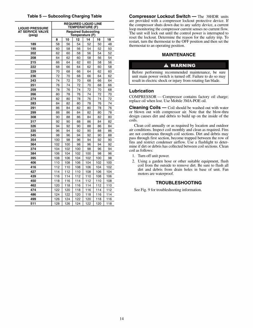
Subcooling Method — For 38HDR units only, the sub-cooling method is used to check and adjust charge during thecooling season. Refer to Table 5 and the following procedure:NOTE: For use with residential fan coils and the 40QA060under ceiling unit only.
1. Operate unit a minimum of 15 minutes before checkingcharge.
2. Measure liquid line temperature near liquid line servicevalve, and measure the liquid pressure at the liquid lineservice valve. Use a digital thermometer for all tempera-ture measurements. DO NOT use mercury or dial-typethermometers.
3. Refer to Table 5. Find the temperature point at which therequired subcooling temperature intersects the measuredliquid line pressure.
4. If the measured liquid line temperature does not agreewith the required liquid line temperature, ADD refriger-ant to lower the temperature, or REMOVE refrigerant toraise the temperature (allow a tolerance of ±3° F).
Table 5 — Subcooling Charging Table Compressor Lockout Switch — The 38HDR unitsare provided with a compressor lockout protective device. Ifthe compressor shuts down due to any safety device, a currentloop monitoring the compressor current senses no current flow.The unit will lock out until the control power is interrupted toreset the lockout. Determine the reason for the safety trip. Torestart, turn the thermostat to the OFF position and then set thethermostat to an operating position.
MAINTENANCE
LubricationCOMPRESSOR — Compressor contains factory oil charge;replace oil when lost. Use Mobile 3MA-POE oil.
Cleaning Coils — Coil should be washed out with wateror blown out with compressor air. Note that the blow-thrudesign causes dirt and debris to build up on the inside of thecoils.
Clean coil annually or as required by location and outdoorair conditions. Inspect coil monthly and clean as required. Finsare not continuous through coil sections. Dirt and debris maypass through first section, become trapped between the row offins and restrict condenser airflow. Use a flashlight to deter-mine if dirt or debris has collected between coil sections. Cleancoil as follows:
1. Turn off unit power.2. Using a garden hose or other suitable equipment, flush
coil from the outside to remove dirt. Be sure to flush alldirt and debris from drain holes in base of unit. Fanmotors are waterproof.
Before performing recommended maintenance, be sureunit main power switch is turned off. Failure to do so mayresult in electric shock or injury from rotating fan blade.
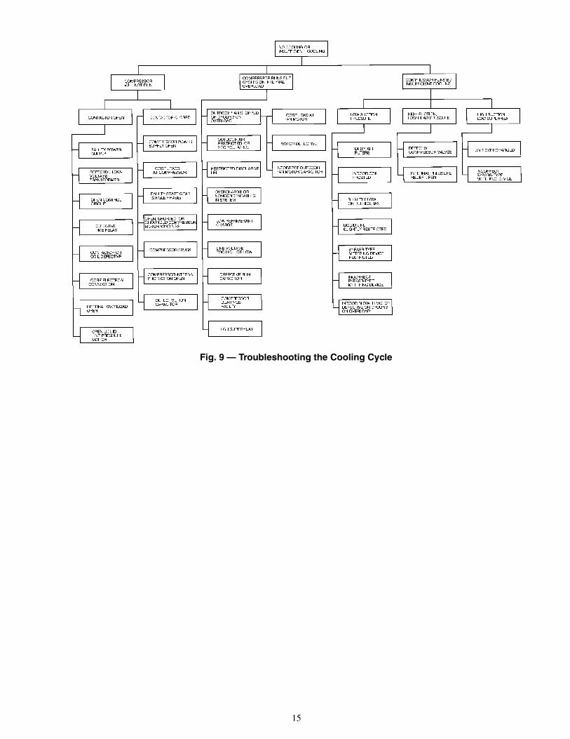
15
Fig. 9 — Troubleshooting the Cooling Cycle
Manufacturer reserves the right to discontinue, or change at any time, specifications or designs without notice and without incurring obligations.Catalog No. 02-38HD0001-SI Printed in U.S.A. Form 38HD-4SI Pg 16 2-06A 1-06 Replaces: 38HDC-3SIBook 1 4