Ratchet5 mm, 6 mm, 10 mm, 12 mm, and 19 mm SocketsPlastic trim tool (T/N SILTRIMTL10)Diagonal cuttersTorque wrenchDrill3 mm Drill bit20 mm Hole sawBlanketEye protection (safety goggles, face shield, etc.)Isopropyl alcoholShop towelAirsaw (T/N AT192A)PushpinFile10 mm Wrench
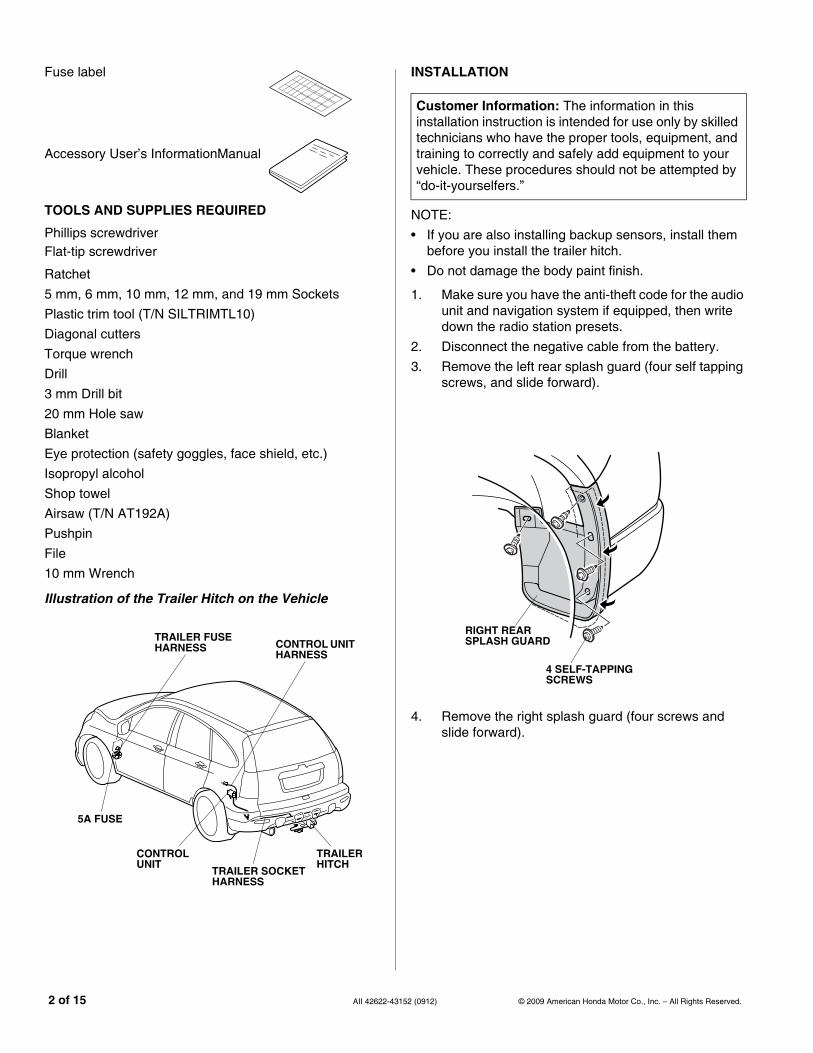
Illustration of the Trailer Hitch on the Vehicle
941601BB
CONTROL UNIT HARNESS
TRAILER SOCKET HARNESS
TRAILER HITCH
CONTROL UNIT
TRAILER FUSE HARNESS
5A FUSE
2 of 15 AII 42622-431
INSTALLATION
NOTE:• If you are also installing backup sensors, install them
before you install the trailer hitch.• Do not damage the body paint finish.
1. Make sure you have the anti-theft code for the audio unit and navigation system if equipped, then write down the radio station presets.
2. Disconnect the negative cable from the battery.3. Remove the left rear splash guard (four self tapping
screws, and slide forward).
4. Remove the right splash guard (four screws and slide forward).
Customer Information: The information in this installation instruction is intended for use only by skilled technicians who have the proper tools, equipment, and training to correctly and safely add equipment to your vehicle. These procedures should not be attempted by “do-it-yourselfers.”
18. Release the drain hose from the two vehicle hooks.
Installing the Trailer Hitch
19. Slide the two muffler hangers off of the vehicle posts, then remove the two muffler hangers from the muffler. Be careful not to damage the muffler.
6805030Y
FRONT
DRAIN HOSE
VEHICLE HOOK
LEFT REAR CARGO AREA OPENING
6828010Y
FRONT
MUFFLER
MUFFLER HANGER
MUFFLER HANGER
152 (0912) 5 of 15
20. Install the two muffler hangers (removed in step 19) onto the hooks of the trailer hitch at the locations shown.
6829010B
TRAILER HITCH HOOK
MUFFLER HANGER
MUFFLER HANGER
TRAILER HITCH HOOK
6 of 15 AII 42622-431
21. With the help of an assistant, install the trailer hitch on the vehicle using the six 10 x 40 mm hex bolts with spring washers and plain washers. Do not tighten the bolts at this time.
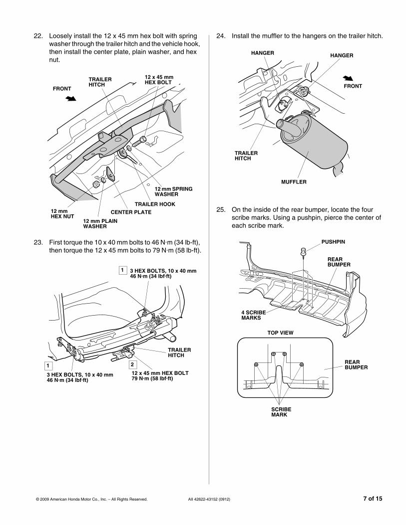
22. Loosely install the 12 x 45 mm hex bolt with spring washer through the trailer hitch and the vehicle hook, then install the center plate, plain washer, and hex nut.
23. First torque the 10 x 40 mm bolts to 46 N·m (34 lb-ft), then torque the 12 x 45 mm bolts to 79 N·m (58 lb-ft).
24. Install the muffler to the hangers on the trailer hitch.
25. On the inside of the rear bumper, locate the four scribe marks. Using a pushpin, pierce the center of each scribe mark.
6306122B
TRAILER HITCH
HANGER
FRONT
MUFFLER
HANGER
941604BB
PUSHPIN
REAR BUMPER
REAR BUMPER
4 SCRIBE MARKS
TOP VIEW
SCRIBE MARK
152 (0912) 7 of 15
26. While wearing an eye protection, drill the rear bumper at each pierced mark using a 20 mm hole saw.
27. Using an airsaw, cut out the rear bumper along the scribe mark as shown.
REAR BUMPER
PIERCED MARK
20 mm HOLE SAW
DRILL
941606BB
AIRSAW(AT192A)
REAR BUMPER
SCRIBE MARK
8 of 15 AII 42622-43
Routing the Trailer Socket/Control Unit Harnesses
28. On the left rear corner of the vehicle, locate and remove the vehicle grommet.
29. Route the 4-pin connector side of the trailer socket harness from the outside to the inside of the vehicle. Seat the trailer socket harness grommet in the vehicle panel hole.
30. Secure the trailer socket harness at the green tape to the vehicle bracket using two wire ties with clips. NOTE: If a backup sensor is also installed, cut the clips from the backup harness wire ties with clip and secure the backup sensor harness to the trailer socket harness near the green tape.
31. Secure the trailer socket harness to the vehicle frame with one additional wire tie.
32. Route the trailer socket harness as shown, and secure the trailer socket harness to the trailer hitch with two 6 x 40 mm flange bolts and two 6 mm flange nuts. Make sure to install the trailer socket harness in the correct position and orientation.
33. Secure the trailer socket harness to the trailer hitch at the green tape using one wire tie.
34. Using an isopropyl alcohol on a shop towel, thoroughly clean the two areas where the harness tapes will attach. Attach one harness tape to the edge of the vehicle panel, and attach the other harness tape to the vehicle panel to secure the trailer socket harness.
35. Inside the vehicle along the left cargo panel, locate the vehicle 8-pin connector blue-taped to the vehicle harness. Remove the blue tape to free the connector.
36. Get the control unit harness. Plug the control unit harness 8-pin connector into the vehicle 8-pin connector you just freed.
6306181B
TRAILER SOCKET HARNESS
FRONT
VEHICLE PANEL
HARNESS TAPE
EDGE OF THE VEHICLE PANEL
HARNESS TAPE
6306190B
CONTROL UNIT HARNESS FRONT
LEFT CARGO PANEL OPENING
CONTROL UNIT HARNESS 8-PIN CONNECTOR
VEHICLE 8-PIN CONNECTORBLUE TAPE
152 (0912) 9 of 15
37. Secure the control unit harness next to the vehicle clip using one wire tie. Don’t wrap the wire tie around the washer tube.
38. Secure the control unit harness to the vehicle harness using two additional wire ties as shown. Don’t wrap the wire ties around the washer tube.
39. Install one wire tie with clip to the control unit harness at the green tape. Note the installation direction of the clip.
6306202B
FRONT
WIRE TIE
GREEN TAPE
CONTROL UNIT HARNESS
VEHICLE CLIPWIRE
TIE
LEFT CARGO PANEL OPENING
630621
FRONT
CONTROL UNITHARNESS
WIRE TIE WITH CLIP(Note the direction.)
GREEN TAPE
LEFT CARGO PANEL OPENING
10 of 15 AII 42622-431
40. Slide the control unit onto the control unit bracket.
41. Plug the control unit harness 12-pin connector into the control unit, then secure the control unit harness to the control unit bracket using the wire tie with clip installed in 39.
45. Loosely thread the 6 x 16 mm flange bolt into the control unit bracket.
46. Install the control unit to the vehicle panel byinserting the 6 x 16 mm bolt through the hole in the panel. Make sure the pin on the control unit bracket is inside the opening before tightening the 6 x 16 mm bolt.
47. Secure the control unit harness to the vehicle panel with one wire tie.
6306263B
IMPORTANT(Pin is inside opening.)
CONTROL UNIT
CONTROL UNIT BRACKET
6 x 16 mm FLANGE BOLT
VEHICLE PANEL
FRONT
CONTROL UNIT HARNESS
VEHICLE PANEL
LEFT CARGO PANEL OPENING
6831030B
WIRE TIE
CONTROL UNITHARNESS
VEHICLE PANEL
FRONT
LEFT CARGO PANEL OPENING
152 (0912) 11 of 15
Routing the Trailer Fuse Harness
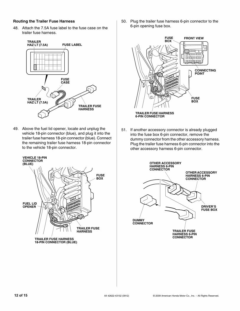
48. Attach the 7.5A fuse label to the fuse case on the trailer fuse harness.
49. Above the fuel lid opener, locate and unplug the vehicle 18-pin connector (blue), and plug it into the trailer fuse harness 18-pin connector (blue). Connect the remaining trailer fuse harness 18-pin connector to the vehicle 18-pin connector.
630701
TRAILER FUSE HARNESS
FUSE CASE
FUSE LABELTRAILER HAZ LT (7.5A)
TRAILER HAZ LT (7.5A)
6307021B
TRAILER FUSE HARNESS
VEHICLE 18-PIN CONNECTOR (BLUE)
FUEL LID OPENER
TRAILER FUSE HARNESS 18-PIN CONNECTOR (BLUE)
FUSE BOX
12 of 15 AII 42622-431
50. Plug the trailer fuse harness 6-pin connector to the 6-pin opening fuse box.
51. If another accessory connector is already plugged into the fuse box 6-pin connector, remove the dummy connector from the other accessory harness. Plug the trailer fuse harness 6-pin connector into the other accessory harness 6-pin connector.
54. Insert the 5A fuse into the fuse box at the empty slot shown.
55. If an optional 5A fuse label is already attached to the driver’s dashboard under cover, go to step 56. Otherwise, using an isopropyl alcohol on a shop towel, thoroughly clean the area where the fuse label will attach. Attach the 5A fuse label to the NO. 27 slot on the driver’s dsshboard undercover.
FUSE BOXFUSE BOX
CONNECTING POINTNO. 27
FRONT VIEW
FUSE (5A)
6829030B
FUSE LABELTRAILER SMALL (5A)
TRAILER SMALL (5A)
DRIVER’S DASHBOARD UNDER COVER
NO. 27FRONT VIEW
152 (0912) 13 of 15
56. Check that all wire harnesses are routed properly and all connectors are plugged in.
57. Reinstall all removed parts.58. Reconnect the negative cable to the battery.59. Enter the customer’s anti-theft code for the radio,
and reset the radio station presets.60. Reset the clock.61. Insert the ball mount into trailer hitch, and install the
Whenever you remove the hitch pin clip, the hitch pin, and the ball mount, store them securely in the cargo area.Install the receiver cover into the opening at the end of the trailer hitch. When you reinstall the ball mount, store the receiver cover in the cargo area.
Install the ball mount into the trailer hitch using a hitch pin and hitch pin clip.
After the first 600 miles (1,000 km) of towing, have your Honda Dealer recheck the torque of the trailer hitch bolts.