Shaping the future of sound reinforcement Installation & User Manual AXYS ® Cerberus Multi I/O interface (Part No. 391010) Multi I/O Surveillance Station Cerberus RS-485 Input 1 RS-485 link Input 2 Inputs CH1 CH17 CH2 CH18 CH3 CH19 CH4 CH5 CH6 CH7 CH8 CH9 CH10 CH11 CH12 CH20 CH21 CH22 CH23 CH24 CH25 DG Y Z B A DG Y Z B A +5V +5V Analog Inputs(0-10V) Outputs max. 200mA
CH20 CH21 CH22 CH23 CH24 CH25 CH26 CH27 CH28 CH29 CH30 CH31 CH32MADE BY DURAN AUDIO BV, ZALTBOMMEL, HOLLAND
CO AC AO CO AC AO CO AC AO CO AC AODG Y Z B A
DG Y Z B A
+5V
+5V
Anal
og In
puts
(0-1
0V)
Out
puts
max
. 200
mA
7 11 18
12 178
9
10
13
14
15
16
fig.3: Rear panel view
REF . PANEl lEGEND ITEM7 RS-485 RS-485 comms port8 RS-485 link RS-485 breakout for further equipment9 Input 1 Analogue DC voltage input 1 10 Input 2 Analogue DC voltage input 211
Inputs (CH1 – CH32)Digital inputs 1 to 16
12 Digital inputs 17 to 3213 Out 1 to Out 4 Relay outputs 1 to 414 Out 5 to Out 8 Relay outputs 5 to 815 Failure Relay A Failure relay contacts A16 Failure Relay B Failure relay contacts B17 Reset Processor hardware reset button18 Mains IEC mains connector with integral fuse-holder
Wiring details for all the rear connectors can be found in subsequent sections of the manual.
AXYS® Cerberus rev 1.0
201605/CERB_1.010
MECHANICAl INSTAllATION
Cerberus is designed to be mounted in a standard 19”
equipment rack. The front panel is fitted with rackmount
ears for this purpose. Cerberus occupies 1U of vertical rack
space.
VentilationCerberus is cooled by natural convection. The unit should
remain within its operational temperature range under
most circumstances, but if it is to be installed in a location
of high ambient temperature, and/or in a rack containing
a significant quantity of heat-generating equipment
(see below), consideration should be given to climate-
controlling the room in which the equipment rack is
situated.
Installation of a Cerberus unit in a 19” rack
immediately above or below another item of
equipment generating a significant amount of heat (e.g., a
power amplifier) is not recommended. Plain or slotted 1U
blank panels should be used as spacers.
CONNECTOR AND wIRING DETAIlS
AC Mainswarning - This apparatus is a Class I device and
must be connected to a mains socket outlet that
provides a safety ground connection.
warning - The Presence of mains voltage is not
indicated by the front panel Power supply OK
LED. This LED indicates the operational status of the unit
and should not be used as a mains voltage indicator.
v
*Numbers in square brackets refer to the figs on pages 8 & 9
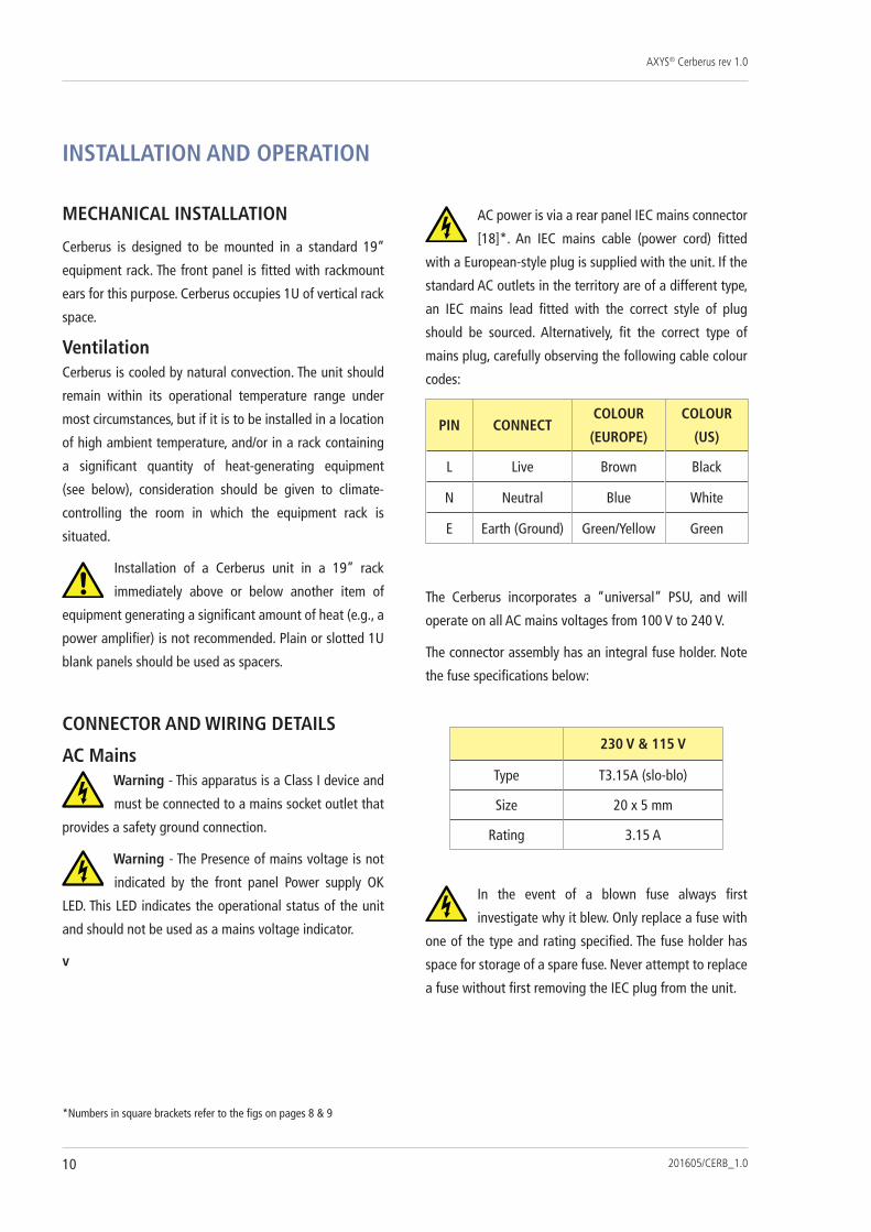
AC power is via a rear panel IEC mains connector
[18]*. An IEC mains cable (power cord) fitted
with a European-style plug is supplied with the unit. If the
standard AC outlets in the territory are of a different type,
an IEC mains lead fitted with the correct style of plug
should be sourced. Alternatively, fit the correct type of
mains plug, carefully observing the following cable colour
codes:
PIN CONNECTCOlOUR
(EUROPE)
COlOUR
(US)
L Live Brown Black
N Neutral Blue White
E Earth (Ground) Green/Yellow Green
The Cerberus incorporates a “universal” PSU, and will
operate on all AC mains voltages from 100 V to 240 V.
The connector assembly has an integral fuse holder. Note
the fuse specifications below:
230 V & 115 V
Type T3.15A (slo-blo)
Size 20 x 5 mm
Rating 3.15 A
In the event of a blown fuse always first
investigate why it blew. Only replace a fuse with
one of the type and rating specified. The fuse holder has
space for storage of a spare fuse. Never attempt to replace
a fuse without first removing the IEC plug from the unit.
INSTAllATION AND OPERATION
AXYS® Cerberus rev 1.0
201605/CERB_1.0 11
Digital InputsConnections to the 32 digital inputs are on 2-pin 3.81 mm-
pitch screw-terminal connectors. Mating connectors are
supplied with the unit.
The inputs are differential, and are designed to operate
on nominal logic levels of 0 and +5 V DC. The maximum
voltage that can be applied at these inputs is ±24 V DC.
fig.4: Digital Input Diagram
Wiring to the digital inputs will depend on the equipment
being connected. Note that the ‘-‘ pin of each input is
referenced to internal ground via a 4.7 kohm resistor.
Connecting to a relay
The ‘+’ and ‘-‘ pins may be connected to an external
relay’s CO/NO or CO/NC volt-free contacts. In this case,
the internal pull-up control will need to be enabled in
WinControl. (Note that the pull-ups are enabled in blocks
of eight inputs).
fig.5: External Relay Connection CO/NC
fig.6: External Relay Connection CO/NO
NOTE: Relays are shown in energised state - i.e., “no-fault”.
AXYS® Cerberus rev 1.0
201605/CERB_1.012
If a changeover relay is available, either NC or NO
contacts may be used, and the logic sense programmed
accordingly. If the relay is only single-contact, establish
from the equipment manual whether it is NO or NC for a
non-fault condition, and use the wiring shown. Note that
impedance-sensing connections, if available, are preferred
for critical applications (see “Connecting to switched-
impedance outputs” on page 13).
Connecting to an open-collector output
Some equipment presents an “open-collector” output.
With this type of output, a transistor is turned on, lowering
its collector voltage to a logic “low” level. The ‘+’ terminal
of the digital input should be returned to the +V rail of
the equipment, which is usually available on an adjacent
terminal. Note that the maximum permissible value of +V
is +24 V.
fig.7: Open-Collector Connection
The pull-up control for a digital input connected to an
open-collector output should be disabled.
Connecting to opto-coupled outputs
If the equipment being monitored uses opto-coupled
outputs, the same principle as above (Connecting to
an open-collector output) should be employed, as the
“switching” part of the opto-coupler is essentially a
transistor. The optical coupling to an LED ensures full
electrical isolation between the item of equipment and
Cerberus.
DIGITALINPUT
EXTERNAL EQUIPMENT
(PULL-UP ENABLED)
+ -
fig.8: Opto-Coupler Connection
The pull-up control for a digital input connected to an
opto-coupled output should be enabled.
AXYS® Cerberus rev 1.0
201605/CERB_1.0 13
Connecting to switched-impedance outputs
Some equipment (including many AXYS products) use
impedance switching to indicate a fault state. Impedance-
sensing has the advantage over simple short/open-circuit
detection in that it can distinguish between unit failure
and cable faults.
fig.9: Impedance-Sensing Connection
The diagram shows a typical arrangement for impedance-
sensed fault indication. The two terminals of the external
equipment may simply be connected to the digital input as
shown. In a no-fault state, the impedance presented to the
digital input is 10 kohms. If a fault condition occurs, the
relay opens, and the impedance rises to 20 kohms.
The pull-up control for a digital input configured for
impedance sensing should be enabled.
Analogue inputsCerberus provides two balanced analogue inputs for
external voltage sensing. (These are referred to as
“Aux inputs” in WinControl.) They may be connected to
any variable DC voltage; possible applications include
temperature sensing, monitoring of back-up battery state
and of external PSU voltage in a relay-controlled redundant
amplifier-switching configuration.
The analogue inputs are on 4-pin 3.81 mm-pitch screw-
terminal connectors. Mating connectors are supplied with
the unit. Two of the four terminals (‘+’ and ‘-‘) constitute
a differential input, and the external voltage being sensed
should be applied across these. Use two-core screened
cable to connect to the external equipment and connect
the screen of the cable to the terminal marked with an
earth (ground) symbol. +5 V is also made available at
the analogue input connector for situations where a DC
voltage is required by a sensor. The DC current which may
be drawn from each of the analogue inputs in this way is
200 mA.
fig.10: Analogue Input Connection
The analogue input is designed to operate in the range
0 to +10 V. Upper and lower thresholds can be set in
WinControl; a fault condition will be registered if the
external analogue voltage is not between the two
thresholds. When configuring the analogue inputs, it is
helpful to open the Properties window (Tools>Status
Properties), open the Input tab and observe the
Aux input properties of the analogue input to
check that the thresholds are being set correctly.
The impedance of the analogue input is 2 Mohms, and
thus will not load the source. The maximum level which
may be applied to the analogue input is ±50 V.
AXYS® Cerberus rev 1.0
201605/CERB_1.014
Relay outputsThe contacts of the each of the eight output relays in the
Cerberus are available on 3-pin 3.81 mm-pitch screw-
terminal connectors. Mating connectors are supplied with
the unit.
The relays are of the single-pole changeover type, and the
contacts are rated at 24 V and 100 mA. The contacts are
volt-free, and are wired internally as shown below:
fig.11: Relay Output Connection
Each output may be configured in WinControl to activate
the relay either according to definable input conditions
(“Failure controlled”), or in response to an RS-485
command from elsewhere in the system (“General
purpose”).
The relay contacts may be wired to whatever signalisation,
alarm or other external equipment is appropriate to the
installation. It is important to remember that any fault
condition defined in Cerberus’s configuration will be
reported to WinControl software via RS-485 to provide
operator visual feedback. The output relays are intended
to be used when a fault condition is required to initiate
specific events automatically in an unattended system.
Using the output relays for amplifier changeover
A further application for Cerberus is as part of a redundant
amplifier setup. A single AXYS IndustryAmp can be used as
a redundant amplifier for up to 8 other audio amplifiers. In
the event of an amplifier failure this redundant amplifier
can be automatically reprogrammed and take over from
the failed one. The AXYS Cerberus unit is used to support
the switching of both audio inputs and loudspeaker lines
in this situation. Please note that additional components
are required.
Full details are beyond the scope of this manual, but an
Application Note covering the topic is available from
Duran Audio on request.
Control connectionsRS-485 interface and link
Cerberus units need a permanent RS-485 network
connection for remote monitoring and control. In most
practical installations, Cerberus will be connected to a
network which includes all other AXYS system components,
such as Octadrive DSP line drivers, amplifiers and active
loudspeakers. This enables the status of the entire audio
system to be monitored and its performance adjusted from
a single location, on a computer running WinControl.
The RS-485 network connection is a 5-pin 3.81 mm-pitch
screw-terminal connector, and should be wired as shown
in the diagram below:
fig.12: RS-485 Wiring
AXYS® Cerberus rev 1.0
201605/CERB_1.0 15
Note that 2-pair cable, with each pair individually-screened,
should be used for RS-485 connection. The transmit (Tx)
and receive (Rx) balanced data lines must be wired via
their own twisted pairs. CAT-5 type UTP or FTP cable is
NOT suitable. Please refer to the Appendix section of the
manual for cable specifications.
The RS-485 interface permits multiple devices to be
“daisy-chained” in parallel (see diagram below), so that
all units are controlled by the same PC. In such a system,
each device must have its own unique network address;
this is set up via WinControl.
fig.13: RS-485 Network
Note the pinout of the RS-485 interface is as follows:
PIN RS-485DG Digital groundY Tx +Z Tx -B Rx -A Rx +
The maximum cable length over which the network
connection will operate reliably depends on the cable type
and the baud rate used. With good quality cable, a safe
maximum figure for the overall network (at 19.2 kbaud) is
2000 m. If the distance is significantly longer than this, a
network repeater will be required.
Before connecting multiple devices to the same
network subnet, ensure that their network
addresses do not overlap. Each device should be set to a
unique network address (determined via WinControl).
In some installations, it is normal practice to
disconnect the RS-485 network from the USB-to-
RS-485 converter at the host (computer) during normal
operation. This removes the possibility of extraneous data
being inadvertently transmitted over the network. In such
a situation, the converter is only reconnected when system
maintenance or checks are required. Disconnecting from
the convertor in this way leaves the Rx lines of the devices
unterminated. In most situations this does not present any
problems, but with a large network in a hostile EMC
environment, it is recommended that the host Y and Z lines
(host Tx/device Rx) are terminated in a 100 ohm resistor
for normal operation. This can be easily achieved by
plugging the XLR5F connector into a spare male connector
with the resistor on the appropriate pins. This termination
can then be removed and the convertor reconnected when
necessary. (If there is any doubt about which pins should
be terminated, shorting all five pins will generally be
equally effective.)
RS-485 link connector
Cerberus, in common with most AXYS products, includes
a hardware “link” (or “loopthrough”) output, for ease
of interconnecting units on the network. In this case, the
network topology is as shown below:
fig.14: Daisy-chain Topology of RS-485 Network
The connector and pinout of the RS-485 Link connector is
identical to that of the RS-485 Interface.
AXYS® Cerberus rev 1.0
201605/CERB_1.016
Failure relay
Cerberus provides a two-pole changeover relay whose
contacts are accessible on two 3-pin 3.81 mm-pitch
screw-terminal connectors. The two poles are electrically
independent, and are marked ‘A’ and ‘B’ on the rear panel.
The pins are labelled CO (changeover), NC (normally-
closed) and NO (normally-open).
Note that in this case, ‘NO’ and ‘NC’ refer to the relay states
as applied to the Cerberus in normal use; ‘NC’ is connected
to ‘CO’ while the unit is powered and operating normally;
in the event of a fault condition, ‘CO’ is connected to ‘NO’.
fig.15: Failure Relay
The conditions under which the relay operates are defined
as part of the unit configuration in WinControl, and may
include network failure, short or open circuit detection at
any digital input, out-of-range voltages at the analogue
inputs, and so on.
Each set of contacts has maximum current and voltage
ratings of 100 mA and 24 V respectively.
STATUS lEDS
The front panel carries a set of five LEDs showing the
status of various unit functions. From left to right:
Power supply OK (green) [2]: illuminates when the
Cerberus is switched on and the PSU is functioning
normally.
Status external failure relay (bi-colour) [3]: normally
green, indicating no fault state exists; turns red to indicate
that a fault condition has de-energised the failure relay.
The conditions defining a failure are set up via WinControl.
Identification (green) [4]: This LED can be illuminated
temporarily (“pinged”) from WinControl. This feature is
provided so that in an installation using multiple AXYS
units, each particular physical unit can be positively
identified if necessary.
RS-485 Send (orange) [5]: indicates that the Cerberus is
transmitting data to the RS-485 network.
RS-485 Receive (orange) [6]: indicates that the Cerberus
is receiving data from the RS-485 network.
AXYS® Cerberus rev 1.0
201605/CERB_1.0 17
CONFIGURING CERBERUS wITH wINCONTROl
The AXYS WinControl software runs on any PC and allows
full control and monitoring of all AXYS products on the
RS-485 network connected to it (normally via a USB-to-
RS-485 interface).
A full description of the operation and use of WinControl
is beyond the scope of this manual. WinControl is supplied
with an extremely comprehensive set of context-sensitive
Help files; please see these for more detailed information.
However, a general overview of WinControl as applied to
Cerberus is given below.
UNIT STATUS
When Cerberus forms part of the active network,
selecting its on-screen icon and pressing F5 will open the
Properties window, which has numerous upper and
lower tabs. The Communications/Failure tab is
illustrated below:
Similar tabs are available which display the status of the
inputs and outputs with various degrees of detail.
DIGITAl INPUTS
Double-clicking the active icon opens the Control
parameters window, where the unit’s configuration
may be defined. The screenshot below shows the digital
inputs configuration page; each input may be named, its
default logic state defined and the type of monitoring
specified; additionally, pull-up control may be enabled and
definitions of short- and open-circuit made.
AXYS® Cerberus rev 1.0
201605/CERB_1.018
ANAlOGUE INPUTS
WinControl allows adjustment of the upper and lower
thresholds, between which the input voltage at the
analogue inputs should remain under no-fault conditions.
OUTPUTS
Each output relay may be configured to activate either as
the result of a defined fault condition, or in response to a
network command.
SURVEIllANCE FUNCTIONS
This page allows definition of the conditions under which
the failure relay changes state.
AXYS® Cerberus rev 1.0
201605/CERB_1.0 19
APPENDIx
TECHNICAl SPECIFICATIONS
Full technical specifications of the AXYS Cerberus are
available at:
http://www.duran-audio.com
MAINTENANCE AND wARRANTY INFORMATION
Maintenance
Maintenance should only be performed by qualified service
personnel. In case of doubt, always contact your dealer. For
cleaning, use non-abrasive and non-aggressive household
cleaning agents only.
warranty Information
This AXYS Cerberus is covered by Duran Audio’s standard
product warranty, and is subject to the terms and conditions
of the warranty. Please consult www.duran-audio.com for
a full statement of warranty policy.
SOFTwARE AND FIRMwARE UPDATES
The AXYS WinControl application is freely available
and can be downloaded from the download area of our
website: www.duran-audio.com. We advise installers,
users and engineers to check our site regularly for updates.
Intellivox firmware and DSP software upgrades will
also be made available through the website. For further
information about how to use WinControl please refer to
the WinControl Help files.
NETwORK CABlES
The type of cable necessary for correct operation of the
RS-485 network is twin twisted pair with each pair
individually shielded. Numerous cables of this type
are readily available and cables broadly meeting the
specifications of the example cable given below are likely
to be suitable.
Example of a preferred cable type:
Type BElDEN ‘Datalene’ series No . 9729 2-pair
Characteristic impedance 100 ohms
Capacitance (core to core) 41 pF/m
Capacitance (core to screen) 72.5 pF/m
DC resistance (core) 78.7 ohms/km
DC resistance (screen) 59.1 ohms/km
DURAN AUDIO BVKoxkampseweg 10, 5301 KK Zaltbommel, The Netherlands.