74
Installation & User Manual (EzSensor Soft / Soft i / Bio / Bio i)

Installation & User Manual (EzSensor Soft / Soft i / Bio / Bio i)

LEFT BLANK INTENTIONALLY
Contents CHAPTER 1 INTRODUCTION...................................................................... 5
1.1 Notice .................................................................................................................. 5
1.2 Conventions and Symbols ................................................................................ 5
1.3 Safety Instructions ............................................................................................ 3
1.4 Disposing of the Product .................................................................................. 6
CHAPTER 2 SYSTEM OVERVIEW .............................................................. 7
2.1 System Description ........................................................................................... 7
2.2 Product Components ........................................................................................ 9
CHAPTER 3 INSTALLATION ..................................................................... 10
3.1 PC Specifications ............................................................................................ 10
1. Recommended Server PC Specifications ........................................................... 10
2. Recommended Client PC Specifications ............................................................ 10
3. Operating System ................................................................................................. 10
3.2 Installation of Software Driver ........................................................................ 11
3.2.1 EzSensor Soft Driver Setup ............................................................................................... 11
3.2.2 Cable connection & Driver Installation ............................................................................. 13
3.3 Installation of the EzSensor Soft Holder........................................................ 15
CHAPTER 4 IMAGE ACQUISITION BY USING EASYDENT ................... 16
4.1 Installation of Easydent................................................................................... 16
4.2 Image Acquisition Overview ........................................................................... 21
4.3 Running the Easydent ..................................................................................... 22
4.3.1 Patient Registration and Device Selection........................................................................ 22
4.3.2 Single Shot ......................................................................................................................... 24
4.3.3 Multi Shot ........................................................................................................................... 28
4.3.4 Sequence Shot ................................................................................................................... 32

CHAPTER 5 IMAGE ACQUISITION BY USING EZDENT-I....................... 35
5.1 Installation EzDent- i ....................................................................................... 35
5.2 License Activation. .......................................................................................... 41
5.3 Consult DB License Activation ....................................................................... 44
5.4 Preparing for Image Acquisition .................................................................... 47
5.5 Running the EzDent- i...................................................................................... 48
5.5.1 Patient Registration ........................................................................................................... 48
5.5.2 Acquiring Image ................................................................................................................. 49
5.5.3 Image View ......................................................................................................................... 54
CHAPTER 6 MAINTENANCE..................................................................... 55
6.1 Visual Inspection ............................................................................................. 55
6.2 Periodic Maintenance ...................................................................................... 55
6.2.1 Test List .............................................................................................................................. 56
6.2.2 Connection ......................................................................................................................... 56
6.2.3 Cable ................................................................................................................................... 57
6.2.4 Resolution .......................................................................................................................... 57
6.3 Care and Cleaning ........................................................................................... 58
6.4 Precautions ...................................................................................................... 58
6.5 Product complaint ........................................................................................... 59
APPENDIX 60
A.1 LED Indicators ................................................................................................. 60
A.2 X-ray Exposure Guide ..................................................................................... 61
A.3 Error Message .................................................................................................. 63
A.4 Troubleshooting .............................................................................................. 65
A.5 Electromagnetic Compatibility Information ................................................... 66

Chapter 1 Introduction
1.1 Notice
For the improvement of Product performance, supplementation, and the follow-up of information,
the contents of this manual are subject to change without prior notice.
Please note that our company bears no responsibility for accidental damage nor will we be
obligated to provide warranty service for any damage to equipment due to user error. Please
follow the instructions in this manual closely. Become familiar with the safety precautions and
usage procedures for this Product. Note that the Product may differ slightly from the contents of
this manual, depending on individual Product specifications.
1.2 Conventions and Symbols 1. Convention
The following symbols are used throughout this manual to provide instructions on the
effective use of this Product.
Indicates useful information and tips on how to use our software and Products.
Indicates important instructions. If not observed, malfunction or damage to the Product or other property may occur.
Indicates warnings and safety instructions. If not adhered to, there is a serious risk of injury to the patient and/or the operator.

2
2. Symbols Descriptions
Item Symbol Description
1
Type B applied part
2
Refer to instruction manual/ booklet
3 Conforms to CE MDD 93/42/EEC (European Communities) concerning medical devices
4
Waste Electrical and Electronic Equipment
5
Manufacturer
6 Date of manufacture
7
Serial number
8
Authorized representative in the European Community
9
Handling procedures for Electro-Static Discharge (ESD).
9
Handle with care
10
Fragile, handle with care
11
This way up
12
Intended for a single use.
For U.S.A. users: United State federal law restricts this device to use by or on the order of physician. For other countries users: This device to use by or on the order of a licensed person under the related laws in each country.

3
13
Indicates important instructions. If not observed, malfunction or damage to the Product or other property may occur.
14
Indicates warnings and safety instructions. If not adhered to, there is a serious risk of injury to the patient and/or the operator.
15
Indicates useful information and tips on how to use our software and Products.
1.3 Safety Instructions Indications for Use
EzSensor Soft, an Intra-oral Imaging device, is intended to collect dental x-ray photons
and convert them into electronic impulses that may be stored, viewed, and manipulated
for diagnostic use by dentists.
Before each usage, check the outer surface of the EzSensor Soft for any signs of physical
damage or defect. The surface of the EzSensor Soft should have a smooth finish, with no
evidence of chipping or damage. Otherwise, contact your local Product distributor for further
instructions on how to proceed.
To ensure the correct usage of the EzSensor Soft device in a clinical environment, for which the
intended purposes correspond to its design and application, only dentists or their designated
operators are authorized to operate this Product
Modifications and/or additions to the device must be conducted exclusively by
MANUFACTURER or by parties expressly authorized to do so by MANUFACTURER. Any
modifications or additions must always comply with the standards and generally recognized
rules of good workmanship.
It is the user’s responsibility to ensure compliance with all local safety regulations in effect in the
jurisdiction of installation.
4
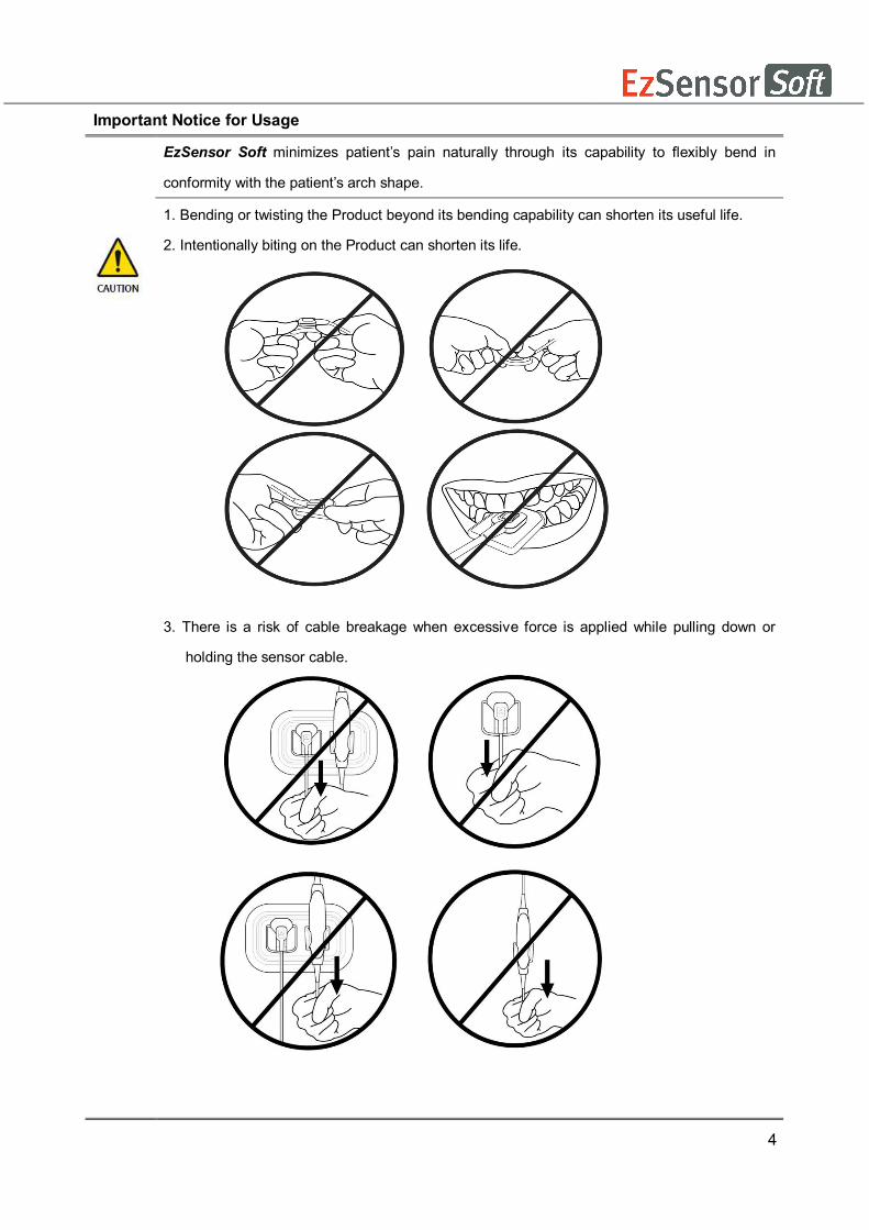
Important Notice for Usage
EzSensor Soft minimizes patient’s pain naturally through its capability to flexibly bend in
conformity with the patient’s arch shape.
1. Bending or twisting the Product beyond its bending capability can shorten its useful life.
2. Intentionally biting on the Product can shorten its life.
3. There is a risk of cable breakage when excessive force is applied while pulling down or
holding the sensor cable.

5
Electrical safety
The covers of the Product may be removed only by qualified and authorized technical
personnel.
This Product can only be used in rooms or areas that comply with all laws and regulations
applicable to electrical safety on medical premises, such as IEC standards for the use of an
additional ground terminal for equipotential connections. This Product must always be
disconnected from the power supply before cleaning or disinfecting.
This Product should be connected with a device which is complied with IEC 60601-1.
Water and other liquids must be kept at a distance to avoid penetration of the Product. Liquids
may cause corrosion or the Product to short circuit. No protection is offered against liquid
penetration.
Explosion safety
This Product is not recommended for use in the presence of flammable gases or vapours.
Some disinfectants evaporate and form explosive or flammable mixtures. If disinfectants of this
kind are used, it is important to let the vapours disperse before using the Product again.
For the improvement of Product performance, supplementation, and follow-up of information,
the contents of this manual are subject to change without prior notice.
X-ray protection
The rules of dental radiography apply to digital X-ray systems. Please continue to use
protection for your patients. As a clinician, clear the immediate area when exposing the sensor.

6
1.4 Disposing of the Product
1. WEEE information according to directive 2002/96/EC
(Waste Electrical and Electronic Equipment)
The crossed-out wheeled bin symbol, that is present on the Product, means that
within the European Union the product must be taken to separate collection at the
product end-of life. Therefore, at the end of the life-cycle of the Product, the user
should deliver the device to the proper collection facilities of the Electric and
Electronic Equipments. Alternatively, the user can return the Product to the seller, on a one-
to-one basis, as long as he or she is buying a new one of equivalent type and that fulfils the
same functions as the old one.
Disposing of the Product separately avoids possible negative consequences for the
environment and health deriving from inappropriate disposal and enables the constituent
materials to be recovered to obtain significant savings in energy and resources.
Who disposes any Electric and Electronic Equipment, reporting the above symbol, as unsorted municipal waste, instead of collecting it separately, incurs the administrative sanctions in accordance with law.
2. Label Location
The label can be found on the EzSensor Soft device.
7
Chapter 2 SYSTEM OVERVIEW
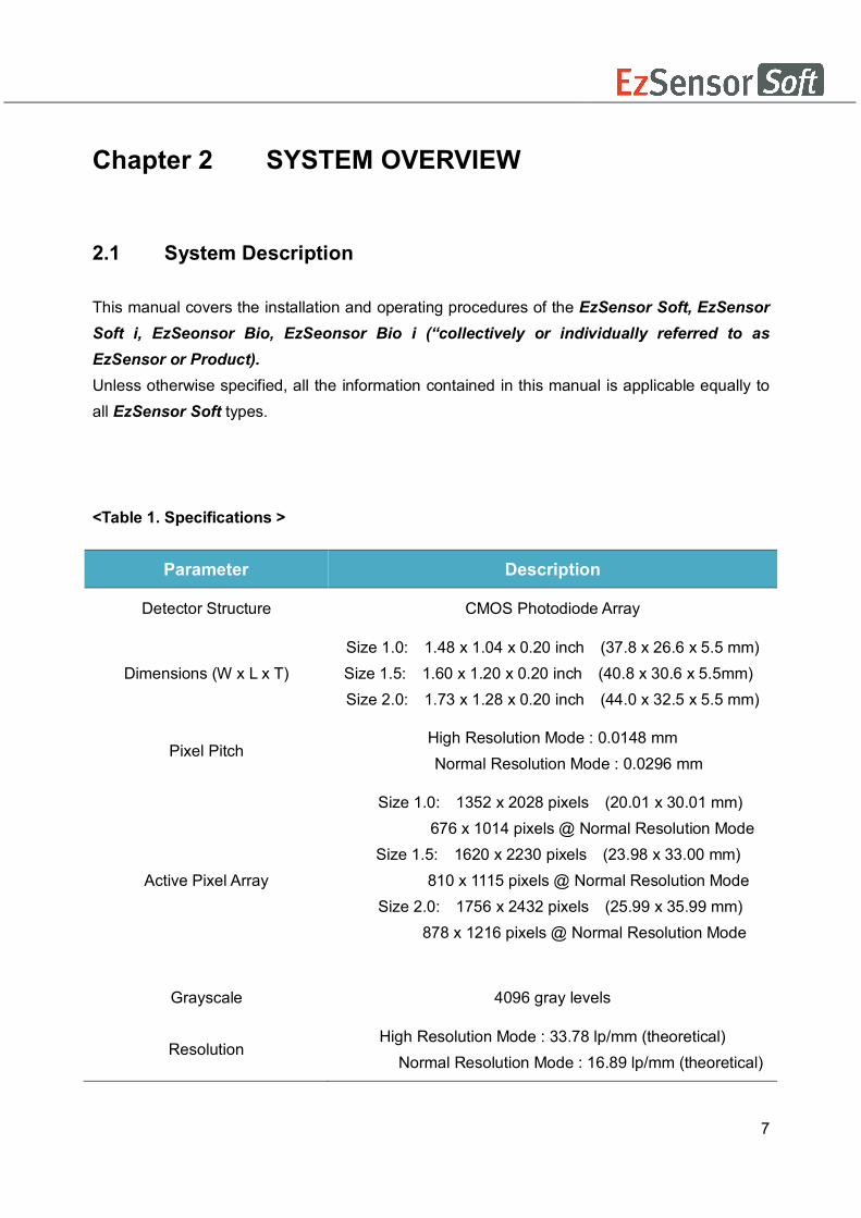
2.1 System Description This manual covers the installation and operating procedures of the EzSensor Soft, EzSensor Soft i, EzSeonsor Bio, EzSeonsor Bio i (“collectively or individually referred to as EzSensor or Product). Unless otherwise specified, all the information contained in this manual is applicable equally to all EzSensor Soft types.
<Table 1. Specifications >
Parameter Description
Detector Structure CMOS Photodiode Array
Dimensions (W x L x T) Size 1.0: 1.48 x 1.04 x 0.20 inch (37.8 x 26.6 x 5.5 mm) Size 1.5: 1.60 x 1.20 x 0.20 inch (40.8 x 30.6 x 5.5mm) Size 2.0: 1.73 x 1.28 x 0.20 inch (44.0 x 32.5 x 5.5 mm)
Pixel Pitch High Resolution Mode : 0.0148 mm
Normal Resolution Mode : 0.0296 mm
Active Pixel Array
Size 1.0: 1352 x 2028 pixels (20.01 x 30.01 mm) 676 x 1014 pixels @ Normal Resolution Mode
Size 1.5: 1620 x 2230 pixels (23.98 x 33.00 mm) 810 x 1115 pixels @ Normal Resolution Mode Size 2.0: 1756 x 2432 pixels (25.99 x 35.99 mm) 878 x 1216 pixels @ Normal Resolution Mode
Grayscale 4096 gray levels
Resolution High Resolution Mode : 33.78 lp/mm (theoretical)
Normal Resolution Mode : 16.89 lp/mm (theoretical)

8
USB Cable length between Controller and PC
Under 3 m
Electrical rating DC 5V, 500mA
Operation mode Global shutter
Ambient Temperature 10℃ to 30℃ (Usage)
-20℃ to 60℃ (Transportation and Storage)
Relative Humidity 30% to 95% (Usage)
10% to 95% (Transportation and Storage)
Air Pressure 700 to 1060 hPa
EU classification Medical Devices 93/42/EEC as a class IIa
Protection against shock Type B applied part
Protection against matter/water IP 68
The Product has to be installed, transported and stored in the permissible
environmental conditions. Use the provided protective package for transporting or
storage. Also, the Product should not operate in oxygen rich or explosive
environments.

9
2.2 Product Components The EzSensor Soft device installer should check the following items listed in the table below
before Product installation. If the serial numbers of the individual parts do not match, do not
install the Product. Contact your local distributor or agent for support.
This Product should be connected with a device or product which is complied with IEC 60601-1.
<Table 2. EzSensor Soft Product components>
No Components Remarks
1. Sensor Module* 2.8m USB cable is all in one
2 Wrap* (Hygienic Sleeves)
3. Holder for Sensor
4 Silicon cover*
5. S/W Installation CD(or USB) EasyDent (or EzDent-i)
6. Driver Installation CD USB Device Driver
7. EzSensor Soft Manual Document
8 Warranty Cerificate Document
* Patient applied part (Inside Patient environment)
Sensor Module:
Consists of a special CMOS sensor specifically designed for use in radiography and
enclosed in a hermetically sealed ergonomic capsule. The sensitive surface of the
sensor is covered with a thin layer of scintillating phosphorous, through which X-ray
radiation is converted into light and then into an electric charge.

10
Chapter 3 INSTALLATION
3.1 PC Specifications 1. Recommended Server PC Specifications
● Workstation ● Operating System: Window 2000 server or higher ● RAM: 4GB or Higher ● HDD: 1TB or higher
2. Recommended Client PC Specifications ● CPU: Core DUO CPU 1.8GHz or Higher ● Main Memory: 2GB of Higher ● Graphic Card : 512MB or Higher ● HDD: 2GB free space ● Display: 1280x1024x32bpp
3. Operating System ● Window 34&64bit: XP(SP1), Vista, 7, 8, 8.1
We cannot guarantee that Easydent(EzDent i) will work properly with an unregistered copy of Microsoft Windows. Therefore, you should use a registered, genuine version of Microsoft Windows.
Turn off the Windows Firewall service for proper communication across the network for the installed database and file servers.
If you need to install additional software on your computer, please install only those that are internationally authorized. Take extra precaution when installing any Active-X controls.
11
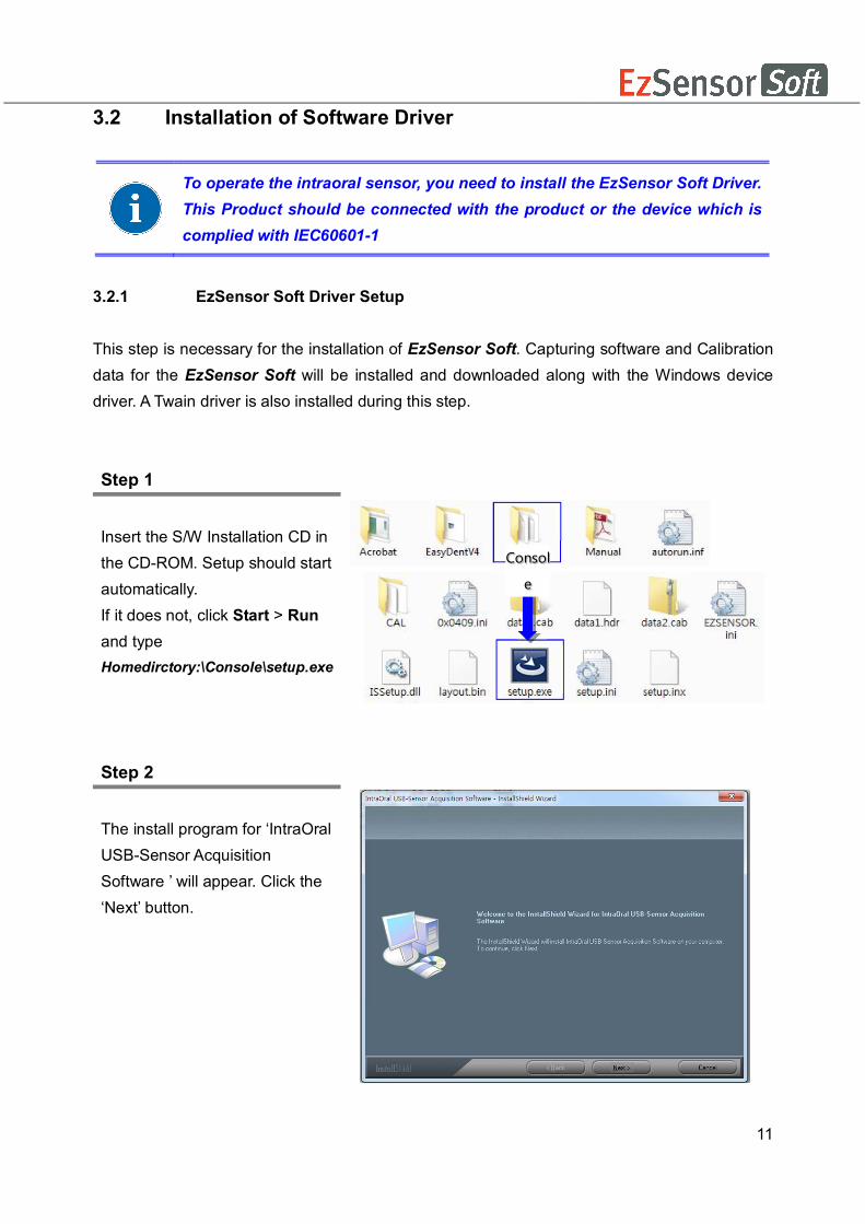
3.2 Installation of Software Driver
3.2.1 EzSensor Soft Driver Setup This step is necessary for the installation of EzSensor Soft. Capturing software and Calibration data for the EzSensor Soft will be installed and downloaded along with the Windows device driver. A Twain driver is also installed during this step. Step 1 Insert the S/W Installation CD in the CD-ROM. Setup should start automatically. If it does not, click Start > Run and type Homedirctory:\Console\setup.exe
Step 2
The install program for ‘IntraOral USB-Sensor Acquisition Software ’ will appear. Click the ‘Next’ button.
To operate the intraoral sensor, you need to install the EzSensor Soft Driver. This Product should be connected with the product or the device which is complied with IEC60601-1
Consol
e

12
Step 3
Check the EzSensor Soft installation directory and then click the ‘Next’ button.
Step 4
The Install shield Wizard will start configuring the installation parameters. The Install-shield wizard will Copy the calibration files To your work-station (PC).
Step 5
The Install-shield wizard will be done.

13
3.2.2 Cable connection & Driver Installation
Step 1
Connect the EzSensor Soft USB Connector to the USB port on the PC directly. Be sure to connect the USB port on backside for accurate operation.
Do not connect the EzSensor Soft and USB PC Interface cable to your computer until you have successfully installed the setup program.
Be sure to connect the EzSensor Soft module to the control board box before connecting the USB PC Interface cable to your computer.
Only connect the item that has been specified as part of the Medical Equipment System.

14
Step 2
Confirmation of Driver installation at the Device Manager. Method of Confirmation:
Windows 7 : Control Panel System and Security System Device Manager Windows XP : Settings Control Panel System Hardware Device manager
Select ‘VH EzSensor-N x.x’, located under Imaging Devices. You should see the message, “This device is working properly”.
EzSensor Soft is supplied to the power and transports data via the USB port of the PC. Do not disconnect during usage.
15
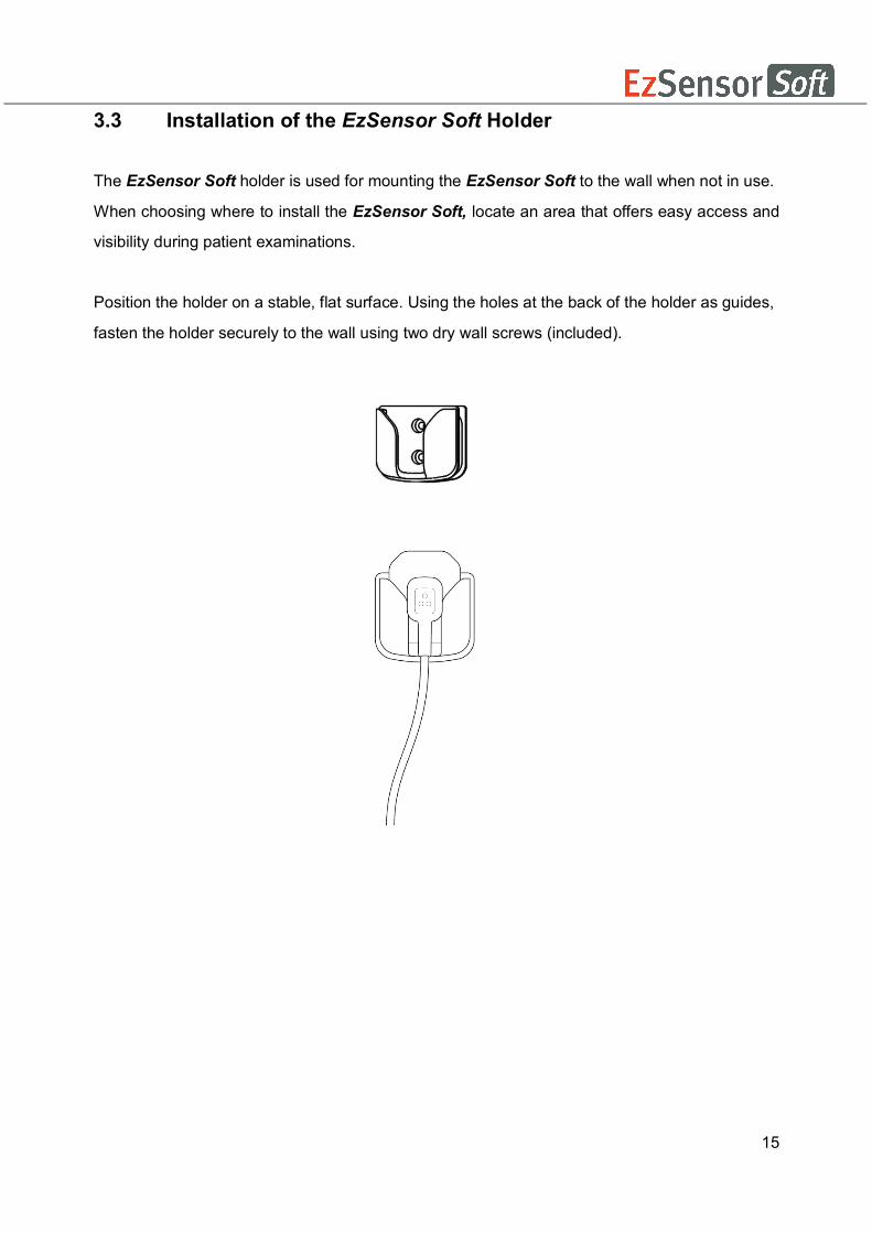
3.3 Installation of the EzSensor Soft Holder
The EzSensor Soft holder is used for mounting the EzSensor Soft to the wall when not in use.
When choosing where to install the EzSensor Soft, locate an area that offers easy access and
visibility during patient examinations.
Position the holder on a stable, flat surface. Using the holes at the back of the holder as guides,
fasten the holder securely to the wall using two dry wall screws (included).

16
Chapter 4 Image Acquisition by using Easydent
4.1 Installation of Easydent
In this step, Easydent will be installed. Alternatively, software which supports the Twain interface can be used instead of Easydent.
Step 1
Insert the S/W installation CD in the CD-ROM drive. Homedirectory:\EasyDent\setup.exe
. Press ‘Enter’.
Step 2
Select the language you want to install and then click ‘Next’.
Consol
e

17
Step 3
The ‘EasyDent V4 InstallShield Wizard’ will appear. Click the ‘Next’ button.
Step 4 Select the setup type that best suits your needs. Click the ‘Next’ button. Basic : Installs the basic version of EasyDent V4 CD-Publishing : Installs the basic version of EasyDent V4 along with CD-Publishing capabilities (optional)
For the EasyDent server, select all items. For PC being used for viewer : Select only the items except for DB & File servers. For the detailed installation, refer to the EasyDent installation manual.
18
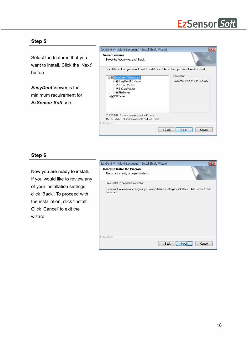
Step 5
Select the features that you want to install. Click the ‘Next’ button.
EasyDent Viewer is the minimum requirement for EzSensor Soft use.
Step 6
Now you are ready to install. If you would like to review any of your installation settings, click ‘Back’. To proceed with the installation, click ‘Install’. Click ‘Cancel’ to exit the wizard.

19
Step 7 Installing EasyDentV4
Step 8
The program compatibility and Windows Firewall alarm messages are shown. Click 'Run program' button on the program compatibility message. And click 'Allow access' button on the windows security message.

20
Step 9
MSDE(Microsoft SQL server Desktop Engine) is installed automatically. Close the SQL Server Service Manager.
Step 10
Select ‘No, I will restart my computer later’, and then click ‘Finish’.

21
4.2 Image Acquisition Overview
① Turn on the computer.
② Run the EasyDent.
③ Configure the required X-ray parameters (exposure time, etc.) for the X-ray generator.
④ Before use the sensor, shooting the X-ray with putting the coin on flat receptor of the
sensor is recommend as an operation test.
⑤ Position the EzSensor Soft at the appropriate area in the mouth. The flat receptor side
of the sensor must face the X-ray source. Note that the receptor side is marked with a
label for ease of recognition
The use of the sensor positioning aid is recommended to guarantee that the sensor is
parallel to the tooth and is at the appropriate angle for exposure
⑥ The use of the parallel technique with a positioning system or device, if possible, is
highly recommended.
⑦ After preparing the sensor for exposure, acquire an image by pressing the exposure
button of your X-ray source.
Normal Resolution Mode This mode is typical operating and general usage and somewhat shows lower resolution, but gets speed of data readout faster.
Using the EzSensor soft
with intraoral X-ray
Using the EzSensor soft
with a Sensor positioning system(optional)

22
4.3 Running the Easydent
Shot functions are available after patient registration and device selection. Single shot, multi
shot, sequence shot are used frequently. You must be fully aware of the explanations before
capturing image.
4.3.1 Patient Registration and Device Selection
Step 1
Turn on the PC. Run EasyDent4 Viewer. Click the ‘Patient ( )’ button to register a new patient.

23
Step 2
The new patient registration window will appear. You are asked to register the new patient and click “Add”.
Step 3
Click ‘Help > Intra-Oral Sensor Setting > Select Device’ on the menu bar. Select your capture device. At this time, you are asked to select the device and image quality. The Product and image processing setting information is stored internally. Change these settings when using another sensor or changing the image processing option. Level 4 is basic image processing option. As the level no. is higher, the effect of contrast and enhancement get increased.
① Level 1
② Level 2
③ Level 3
④ Level 4
⑤ Level 5
⑥ Level 6
⑦ Level 7
24
4.3.2 Single Shot
Capture a single image.
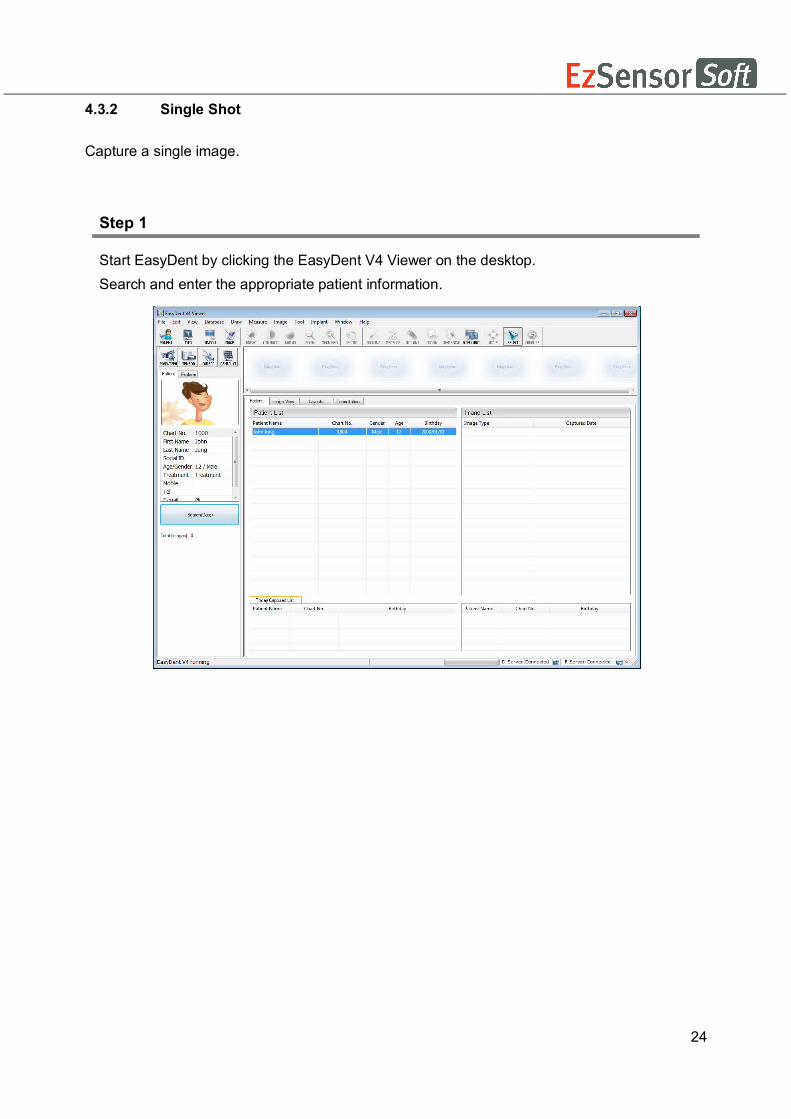
Step 1
Start EasyDent by clicking the EasyDent V4 Viewer on the desktop. Search and enter the appropriate patient information.
25
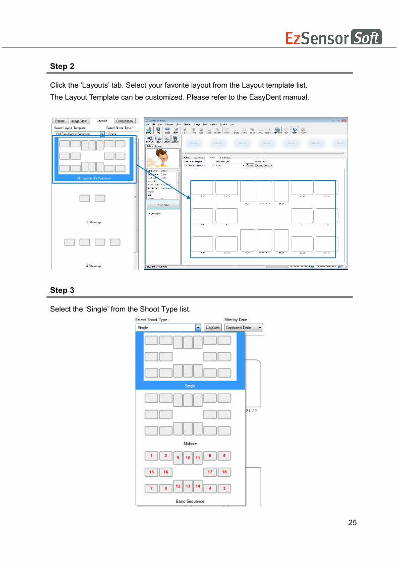
Step 2
Click the ‘Layouts’ tab. Select your favorite layout from the Layout template list. The Layout Template can be customized. Please refer to the EasyDent manual.
Step 3
Select the ‘Single’ from the Shoot Type list.

26
Step 4
Select the tooth position to capture. The tooth box is selected in blue.
Step 5
Click the ‘SENSOR ( )’ button or ‘Capture ( )’ button.
Step 6
Position the sensor correctly.

27
Step 7
After checking the sensor is in the correct position, expose the X-ray after the “Please expose X-ray” message appears. The message, “Optimizing Image… Please wait” appears while the image is being optimized. The image will appear after optimization is complete.

28
4.3.3 Multi Shot
You can capture multiple images continuously until you click stop. Click and drag the image to its appropriate position after stopping capture.
Step 1
Select the ‘Multiple’ from the Shoot Type list.

29
Step 2
Select the tooth position to capture. A blue rectangle will be drawn on the tooth box.
Step 3
Click the ‘SENSOR ( )’ button or ‘Capture ( )’ button.
Step 4
Position the sensor correctly.
30
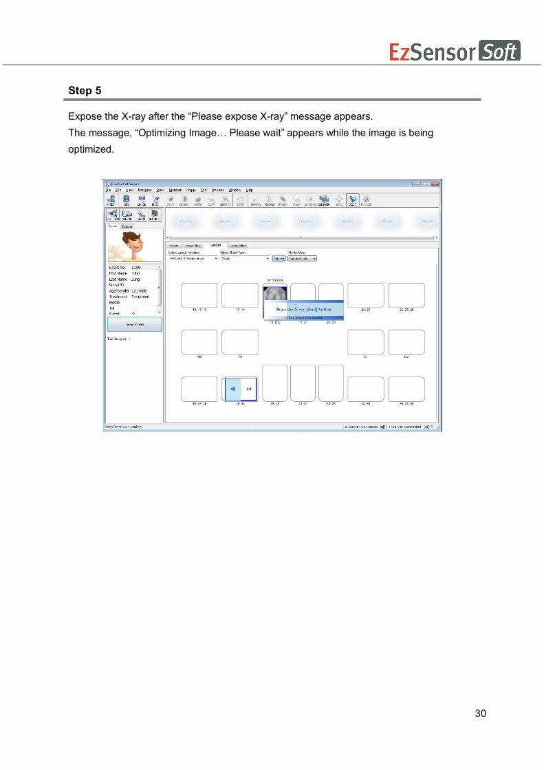
Step 5
Expose the X-ray after the “Please expose X-ray” message appears. The message, “Optimizing Image… Please wait” appears while the image is being optimized.

31
Step 6
If you want to acquire more images, continue to expose the x-ray when the ‘Press the X-ray (shot) button’ message appears. To finish, double click on the ‘Press the X-ray (shot) button’ message box. And then the image will appear after optimization is complete.
Step 7 Click and drag the image to its appropriate position.

32
4.3.4 Sequence Shot
You can capture multiple images according to a pre-saved order. Capturing according to the order will ensure the images appear automatically in the correct positions.
Step 1
Select your favorite sequence from the Shoot Type list. Red numbers represent the capture order. The Sequence shot can be customized. Please refer to the EasyDent manual.
Step 2
Click the ‘SENSOR ( )’ button or ‘Capture ( )’ button.
Step 3
Position the sensor correctly.
33
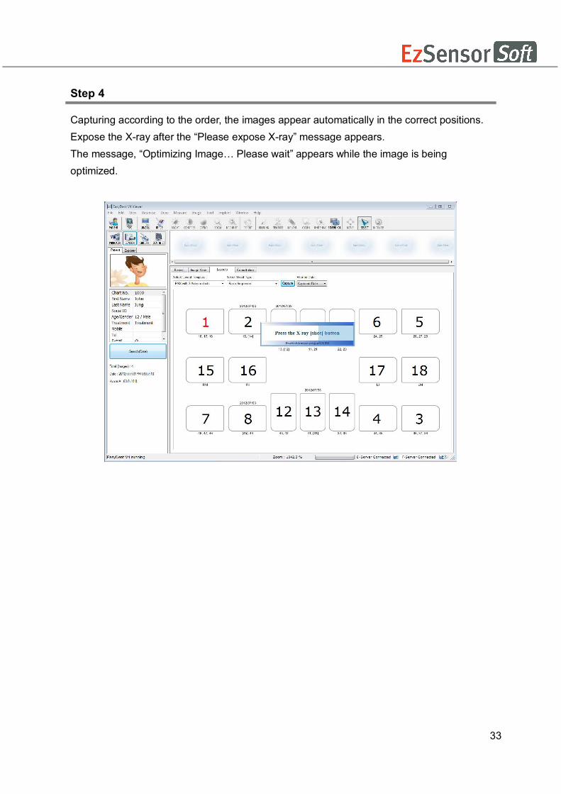
Step 4
Capturing according to the order, the images appear automatically in the correct positions. Expose the X-ray after the “Please expose X-ray” message appears. The message, “Optimizing Image… Please wait” appears while the image is being optimized.
34
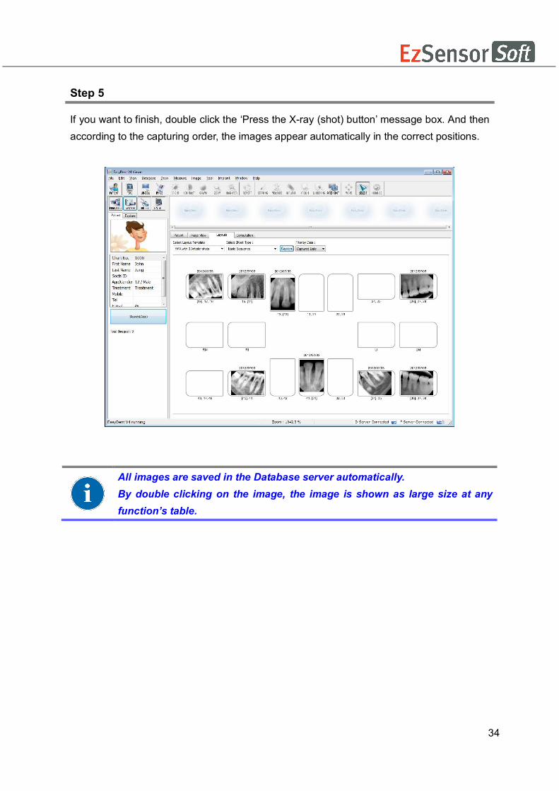
Step 5
If you want to finish, double click the ‘Press the X-ray (shot) button’ message box. And then according to the capturing order, the images appear automatically in the correct positions.
All images are saved in the Database server automatically. By double clicking on the image, the image is shown as large size at any function’s table.

35
Chapter 5 Image Acquisition by using EzDent-i
5.1 Installation EzDent- i
In this step, EzDent i will be installed. Alternatively, software which supports the Twain interface can be used instead of EzDent i.
Step 1
Open [Setup.exe] from [Setup] folder to install EzDent-i Sever or Client for Windows.
Step 2 The window for selecting installation mode will be shown. To setup the Server environment, start the installation by clicking the [Server] button.

36
Step 3 The window for component setting will be displayed After selecting programs to install among EzServer, ConsultData, and Implant DB, click the [EzServer] button.
Step 4 To continue click the [Next] button, followed by the [install] button to proceed.
When the installation of EzServer is complete, the other components (ConsultData and ImplantDB) will automatically start installing.
If users did not select any other components, the installation is finished.

37
Step 5 Users can select the installation type of Implant DB, If users prefer to install multiple fixture models, select [complete], click the [Next] button to proceed.
Step 6
In case that [Custom] in implant DB is selected, Select the name of manufacturers you want to install and click the [Next] button to go forward.
If users prefer to install the implant models separately, select [Custom] and click the [Next]button

38
Step 7 Complie [setup.exe] and click the button, [EzDent-i], ‘The License Agreement’ window will be shown. If the conditions are acceptable, select [I accept the terms of the license agreement] and click [Next] button
39
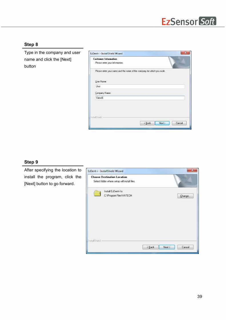
Step 8
Type in the company and user name and click the [Next] button
Step 9 After specifying the location to install the program, click the [Next] button to go forward.

40
Step 10 After installation of EzDent-i Console is complete, select [Yes, I want to restart my computer now] and click the [Finish] button. Then, the PC will be restarted.
It is strongly recommended to restart the PC to apply the changes occurring in the system during the EzDent-i installation.

41
5.2 License Activation.
Step 1 Connect the USB Dongle Key to the PC, and open VTNL. exe
Opening VTNL
To open VTNL program, install ADB.exe file first. If the executable file is
not installed, the installation process of ADB program will automatically
start when opening VTNL program.
42
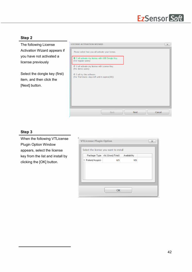
Step 2 The following License Activation Wizard appears if you have not activated a license previously Select the dongle key (first) item, and then click the [Next] button.
Step 3
When the following VTLicense Plugin Option Window appears, select the license key from the list and install by clicking the [OK] button.

43
Step 4 After clicking the [OK] button, the following VTLicense Activation Wizard window appears. Once the license has been activated, click on the [Finish] button to complete your activation. EzDent-I will then run automatically.
Once the license has been activated, the user’s PC will appear on the list of [Certifications] in the VTNL window.
The dongle license key number appears on the list of [Volume] in the VTNLwindow.

44
5.3 Consult DB License Activation
Step 1
Open[Setup.exe] from [Setup] folder to install EzDent-i Server or Client for Windows
Step 2
After selecting the install modes, Click the [Consult License Activator] button
Consult DB is for the users who have a Consult Premium License. After activating Consult DB License, the user can utilize video contents for consultation use.

45
Step 3
After checking the license information shown at the Consult Data License Activator window, Click the [Activate] button.
Step 4
Select the second option from the VTLicense Activation Wizard window.
For activating license using the license key, an internet connection must be available with the PC.

46
Step 5
Enter the EzDent-i user information and license key provided. And then click the [Next] button. You must enter more than 3 characters to activate the [Next] button.
Step 6
Upon successful activation, the VTLicense Activation Wizard window will appear, including the remaining days. Click the [Finish] button to end the activation. .

47
5.4 Preparing for Image Acquisition
① Turn on the computer.
② Run the EzDent-i.
③ Configure the required X-ray parameters (exposure time, etc.) for the X-ray generator.
④ For the operation test before X-ray exposure to patients, X-ray exposure as putting the
coin on flat receptor of the sensor is recommend.
⑤ Position the EzSensor Soft at the appropriate area in the mouth. The flat receptor side
of the sensor must face the X-ray source. Note that the receptor side is marked with a
label for ease of recognition
The use of the sensor positioning aid is recommended to guarantee that the sensor is
parallel to the tooth and is at the appropriate angle for exposure
⑥ The use of the parallel technique with a positioning system or device, if possible, is
highly recommended.
⑦ After preparing the sensor for exposure, acquire an image by pressing the exposure
button of your X-ray source.
Using the EzSensor soft
with intraoral X-ray
Using the EzSensor soft
with a Sensor positioning system(optional)

48
5.5 Running the EzDent- i
5.5.1 Patient Registration
Step 1
Turn on the PC. Run EzDent-i. Click the ‘Patient ( )’ button to register a new patient.
Step 2
The “Add Patient” registration window will appear. Register the new patient and click “Add.”

49
5.5.2 Acquiring Image
Step 1 The Acquisition Tab allows the user to capture/store images with the IO Sensor.
By clicking the logo, “EzDent-i” as below, you can select resolution mode between Normal and High. If resolution mode is changed, restarting program is required.

50
Step 2
Normal Resolution Mode This mode is typical operating and general usage and somewhat shows lower resolution, but gets speed of data readout faster.
Click the [IO Sensor] button in the Acquisition tab. Once the IO sensor is connected, the layout will change depending on the selected device.
Step 3 Click the [Ready] button after positioning the patient. If the IO Sensor equipment is properly connected, the image acquisition mode will be initiated.
51
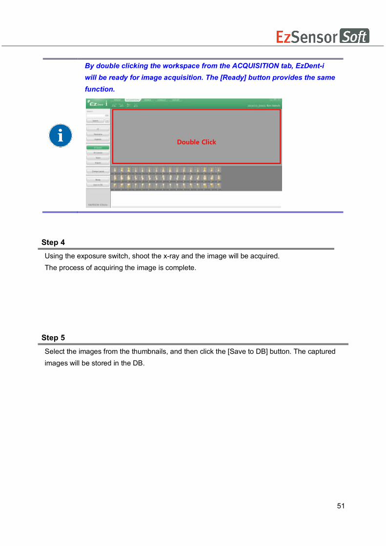
Step 4 Using the exposure switch, shoot the x-ray and the image will be acquired. The process of acquiring the image is complete.
Step 5 Select the images from the thumbnails, and then click the [Save to DB] button. The captured images will be stored in the DB.
By double clicking the workspace from the ACQUISITION tab, EzDent-i will be ready for image acquisition. The [Ready] button provides the same function.
Double Click
52
If the user wants to select more than 2 images, hold the Ctrl key on the keyboard and click the desired images from the thumbnails.
To change the way of storing the acquired images, change the options in settings. All the acquired images are automatically stored in DB if the “Auto DB Save” option is used and only the selected images are stored in DB with the “Manual” option is used.

53
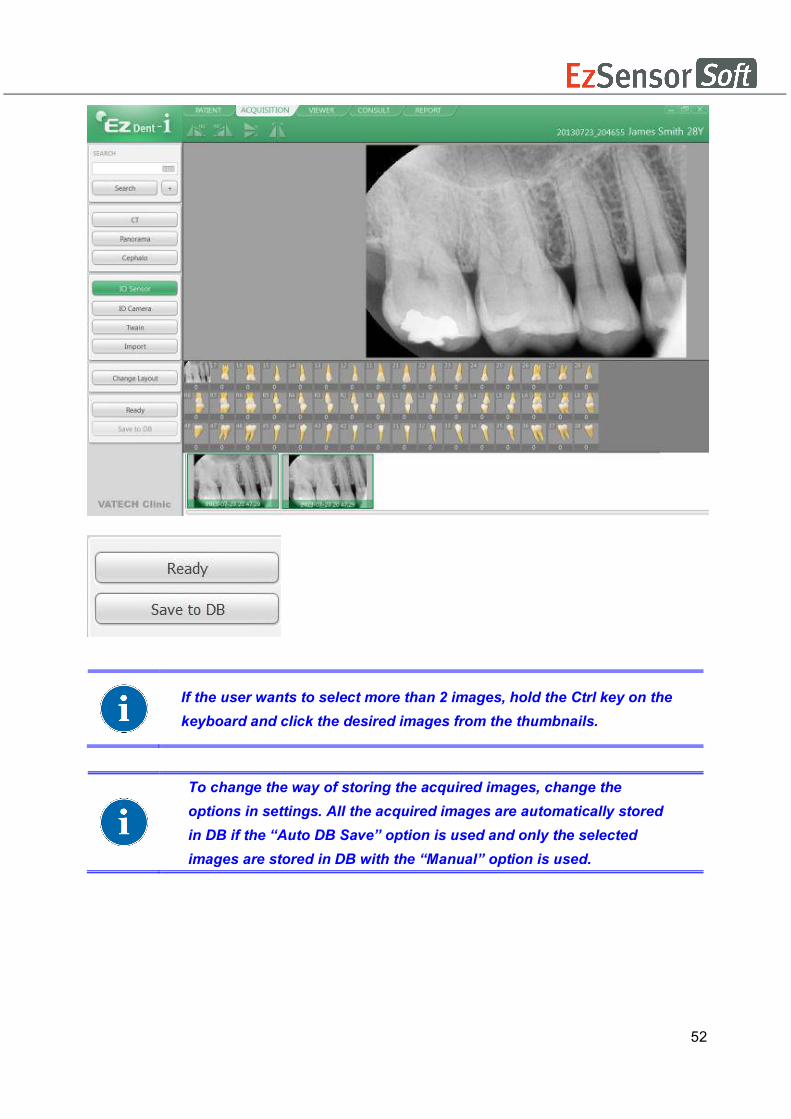
Step 6 Select the images from the thumbnails, and then click the [Save to DB] button. The captured images will be stored in the DB.
If the user wants to select more than 2 images, hold the Ctrl key on the keyboard and click the desired images from the thumbnails.
To change the way of storing the acquired images, change the options in settings. With the option “Auto DB Save,” all acquired images are automatically stored in DB. Another option, Manual, only stores selected images in DB.

54
5.5.3 Image View
Step 1 Enter the name or chart number of the patient in the Patient Search window and click the [Search] button or press the Enter key. The search result will appear.
Step 2 Double Click the selected “Patient List”. The images will be displayed in the VIEWER tab.

55
Chapter 6 Maintenance
For optimal performance, MANUFACTURER recommends the working area be kept clean.
There are no specific cleaning requirements for the EzSensor Soft beyond normal care and
attention for aesthetic appearances.
6.1 Visual Inspection Like all electrical systems or device, EzSensor Soft requires not only correct usage, but also
visual inspection prior to operation, as well as routine checks at regular intervals. These
precautions will help ensure that the Product operates accurately, safely, and efficiently.
Before use, the operator should check the Product for any signs of physical damage or defects.
If something out of order is suspected, contact your local Product distributor for further
instructions on how to proceed.
6.2 Periodic Maintenance
Periodic maintenance should be performed as necessary and in accordance with monitored
frequency in the table below. Maintenance should consist of various checks performed by the
operator or by a qualified service technician.
● Check that all cables connected to the EzSensor Soft are undamaged.
● Check for any external damage to the EzSensor Soft that may compromise its ability to
be safely operated. If the EzSensor Soft is defective, the sensor should be returned to the
manufacturer for repair.
● Arrange the sensor and the control box USB cable to prevent damage of the cable’s
rubber tube. They should not be stepped on nor bent and pressed under table legs.
A qualified service technician is a person authorized by Rayence or affiliated distributors.
56
6.2.1 Test List
Test Item Frequency Equipment
Connection Daily Sensor & PC
Cable Monthly Cable
Resolution Annually Resolution Patterns, Gammex rmi
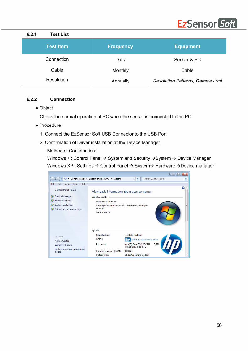
6.2.2 Connection
● Object
Check the normal operation of PC when the sensor is connected to the PC
● Procedure
1. Connect the EzSensor Soft USB Connector to the USB Port
2. Confirmation of Driver installation at the Device Manager
Method of Confirmation: Windows 7 : Control Panel System and Security System Device Manager Windows XP : Settings Control Panel System Hardware Device manager

57
3. Select ‘VH EzSensor-N x.x’, located under Imaging Devices. You should see the
message, “This device is working properly”.
6.2.3 Cable
● Object
Prevent the sensor malfunction caused by the occurrence of external cable stress.
● Procedure
1 . Arrange the sensor and the control box USB cable to prevent damage of the cable’s
rubber tube. They should not be stepped on nor bent and pressed under table legs.
2. Check that all cables connected to the EzSensor Soft are undamaged.
6.2.4 Resolution
● Object
Verify the resolution of EzSensor Soft
● Procedure
1 . Run EasyDent(EzDent-i) with connecting EzSensor Soft .
2. Attach resolution phantom on the center of the detector with diagonal direction.
3. Set X-ray Condition to 60~70kVp 50mAs and SID to 28cm
4. Confirm that the resolution is over 8lp/mm.

58
6.3 Care and Cleaning In order to prevent infection, wipe the front plate of the sensor unit with ethanol or
glutaraldehyde solution to disinfect it each time a different patient uses the instrument. If you
plan to use a disinfectant other than those specified above, or you are mixing another
disinfectant with ethanol, please consult a specialist because it may damage the plate.
To clean the EzSensor Soft, the following solutions are listed below. Please observe the
precautions noted. (Do not use any type of solvent, such as alcohol or benzene.)
● Mild soap and water
● Isopropyl alcohol (70%)
● Most alcohol and ammonia based cleaners
● Mild, non-abrasive cleaners Do not soak or immerse any part of the Product, and be sure to dry it completely after cleaning.
Clean the surface of the Product by moistening it with a soft cotton swab dipped in one of the
cleaning solutions listed above. Gently wipe the surface end-to-end in straight lines, without
applying any pressure. Make sure the liquid does not penetrate the Product through the USB
cable or the sensor cable connectors.
After cleaning the surface of the EzSensor Soft, use a clean lint-free cloth to dry the Product,
as required, until the surface is clean. ※Clean the silicone cover using the same method.
※ Do not use the following cleaning materials.
● Hard brushes or scrapers of any kind
● Strong acids or alkaloids
6.4 Precautions
● Do not soak the sensor in water or alcohol.
● Authorized service personnel can repair calibration issues.
● Service personnel cannot handle problems that are not mentioned in this manual.
Please request repairs to the manufacturer through a VATECH dealer.
● Equipment and accessories are to be disposed safely at the end of the Product life
cycle. National regulation must be observed.

59
6.5 Product complaint Any health care professional (e.g., a customer or user of Product or system) who has any
complaints should notify his or her distributor first, who will handle such issues.
If the Product may have caused or contributed to a serious injury of a patient, your distributor
should immediately notify the manufacturer by telephone, fax, or written correspondence. The
manufacturer will report it to the government according to their reporting process.
Do not modify this equipment without authorization of the manufacturer.

60
Appendix
A.1 LED Indicators
The EzSensor Soft Hardware Controller has two LED indicators that show its functional status.
The location of the LED lights is as shown in the following illustration and described in Table 3.
<Table 3. Description of LED Indicators>
Operational State LED State Functional Status
Confirmation LED
Initial State BLUE USB Connection
Standby GREEN Capture standby
Trigger (X-ray On) YELLOW X-ray On and Sensor Trigger On
Data Transmission with the USB PC interface cable YELLOW Confirm data transmission
with the sensor board
LED
61
A.2 X-ray Exposure Guide The required X-ray dose for the best image is dependent on the following:
- X-ray source (tube assembly, manufacturer, AC/DC, etc.) - Distance between beam focus and sensor - Tooth (object) to be X-rayed - Bone density and age of patient - Miscellaneous circumstances, etc.
The X-ray dose influences image quality. Based on fundamental laws of physics, an insufficient dose generally means higher image noise, which leads to poor detail discrimination. On the other hand, an excessively high dose can cause the sensor to be overexposed. This is also perceptible by a decrease in detail discrimination, specifically in darker areas. The effect of image processing reduces the difference between image qualities of different doses. Users can adjust brightness and contrast in the option menu. The recommended exposure dose is from 300μGy to 600μGy when measuring without an object. Exposure time corresponding to the dose may vary depending on the X-ray equipment used. Recommended exposure times according to positions are as shown on the Exposure Time Table. The X-ray dose is maintained through tube voltage (kVp) and current (mA), as well as exposure time according to the signal level.
Since the exposure time depends on the diagnostic problem as well as the clinical situation, the selection of an adjustment is the responsibility of the treating physician.
Image degradations caused by overexposure of the sensor cannot be compensated, but an insufficient dose can be partially compensated through image processing.

62
< Table 4. Recommendation on Exposure Time >
Exposure condition
Dose (μGy)
60kvp 6mA
60kVp 2mA
65kVp 5mA
Patient Adult Adult Adult
SID 28cm 18cm 28cm
Intra Oral X-ray Unit (Model name)
No Filter
VX 70 AnyRay ESX
Approximate Exposure Time (sec) Incisor
& Canine
300 ~ 500 0.12 ~ 0.2 0.1 ~ 0.2 0.18 ~ 0.28
Molar 400 ~ 600 0.16 ~ 0.25 0.15 ~ 0.25 0.24 ~ 0.34
* SID : Source to imaging receptor Distance
* Recommendation on Exposure Time is limited to Intra Oral X-ray Unit in the above table
For larger body types : increase the source current by 25% For children(5~21age) : reduce the source current (or Exposure time)
by 20% For edentulous patients : reduce the source current by 20%.
Since the X-ray exposure condition can be changed depending on the age, gender and bone densitiy of the patient, in case of Pediatric, X-ray exposure condition can be changed by expert’s judge. For further information, please refer to FDA Pediatric X-ray Imaging webpage, http://www.fda.gov/radiation-
emittingproducts/radiationemittingproductsandprocedures/medicalimaging/ucm298899.htm)
The X-ray dose required for image acquisition can vary depending on the X-ray source and environmental circumstances. You must maintain the exposure time and change the kVp and mA values according to the signal level. In addition, if the X-ray source and the distance to the sensor were changed during the initial installation, the distance (from cone to detector) must be changed to the 80mm setting. The exposure time may vary depending on the age, gender, and bone density of the patient.
63
A.3 Error Message
1. USB device driver is not installed. ● Solution: Please install the device driver again.
2. Control box cannot be initialized.
● Solution: Check and re-connect the USB PC interface cable. 3. USB device driver is not working properly.
● Solution: Re-install the driver. 4. Capture program is already running.
● Solution: Please close any other programs. 5. Detector response time-out.
● Check and re-connect the USB PC interface cable. Please try again. If the same message is displayed again, contact Customer Service.
6. Data communication error.
● Solution: Re-connect the USB PC interface cable. 7. Canceled image capturing.
●This means that the user canceled image capture. Please try again. 8. Cannot find dark frame.
● Solution: Restore the EzSensor Soft’s calibration data from the S/W installation CD or re-calibrate the sensor. If the same message is displayed again, contact Customer Service.
9. Cannot find bright frames for calibration.
● Solution: Reinstall the EzSensor Soft driver. 10. Bad Pixel Map correction error.
● Solution: Restore the EzSensor Soft’s calibration data from the S/W installation CD or re-calibrate the sensor. If the same message is displayed again, contact Customer Service.

64
11. Wrong image processing parameters.
● Solution: Check the X-ray source. If the problem persists, call for technical assistance. 12. Cannot load 'EzSensor.dll'.
● Solution: Please re-install the acquisition software. 13. Require 'EzSensor.dll' was damaged.
● Solution: Please re-install the acquisition software.

65
A.4 Troubleshooting
If you experience any problems regarding the EzSensor Soft during operation, please refer to
the troubleshooting table below for corrective measures. If the problem persists, please contact
your local Product distributor.
<Table 5. Troubleshooting Table>
Item Description Corrective Measure
1 LED 1 on the control board box does not illuminate after installing the Product.
Check that the USB PC interface cable is plugged in correctly at the control board box and on the console PC.
2
A ‘PID 2XXX NO; interface #0 (Check Connection)’ error message is displayed.
Unplug the USB PC interface cable from the control board box and then reconnect it. Open the Windows Device Manager and check that the device is installed correctly. Alternatively, try another USB port on your computer.

66
A.5 Electromagnetic Compatibility Information
Guidance and manufacturer’s declaration – electromagnetic emissions
The Product is intended for use in an electromagnetic environment as specified below. The customer or the user of the Product should ensure that it is used in such an environment.
Emissions test Compliance Electromagnetic environment - guidance RF emissions CISPR 11
Group 1 The Product uses RF energy only for its internal functions. Therefore, its RF emissions are very low and are not likely to cause any interference to nearby electronic equipment.
RF emissions CISPR 11
Class A The Product is suitable for use in all establishments, including domestic establishments, and those directly connected to a personal computer USB port used for domestic purposes. Harmonics
emission IEC 61000-3-2
A
Voltage fluctuation IEC 61000-3-3
Complies
Guidance and manufacturer’s declaration – electromagnetic emissions The Product is intended for use in an electromagnetic environment as specified below. The customer or the user of the Product should ensure that it is used in such an environment. Immunity test IEC 60601
test level Compliance level
Electromagnetic environment – guidance
Electrostatic discharge (ESD) IEC 61000-4-2
6 kV contact 8 kV air
6 kV contact 8 kV air
Floors should be wood, concrete or ceramic tiles. If floors are covered with synthetic material, relative humidity should be at least 30%.
Electrical fast transient/burst IEC 61000-4-4
2 kV for power supply lines 1 kV for input/output lines
2 kV for power supply lines 1 kV for input/output lines
Mains power quality should be that of a typical commercial or hospital environment.
Surge IEC 61000-4-5
1 kV differential mode 2 kV common mode
1 kV differential mode 2 kV common mode
Mains power quality should be that of a typical commercial or hospital environment.
Voltage dips, short interruption, and voltage variations on power supply input lines IEC 60601-4-11
< 5 % UT (> 95 % dip in UT) for 0.5 cycles 40 % UT (60 % dip in UT) for 6 cycles 70 % UT (30 % dip in UT) for 30 cycles < 5 % UT (> 95 % dip in UT) for 5 s
< 5 % UT (> 95 % dip in UT) for 0.5 cycles 40 % UT (60 % dip in UT) for 6 cycles 70 % UT (30 % dip in UT) for 30 cycles < 5 % UT (> 95 % dip in UT) for 5 s
Mains power quality should be that of a typical commercial or hospital environment. If the user of the Product requires continued operation during power mains interruptions, it is recommended that the Product be powered from an uninterruptible power source or battery.
Power frequency 3.0 A/m 3.0 A/m Power frequency magnetic fields should

67
(50/60 Hz) IEC 61000-4-8
be at levels characteristic of a typical location in a typical commercial or hospital environment.
Conducted RF IEC61000-4-6
3 Vrms 150 kHz to 80MHz
3 Vrms 150 kHz to 80MHz
Portable and mobile RF communications equipment should be used no closer to any part of the Product, including cables, than the recommended separation distance calculated from the equation applicable to the frequency of the transmitter. Recommended separation distance
Radiated RF IEC61000-4-3
3 V/m 80 MHz to 2.5GHz
3 V/m 80 MHz to 2.5GHz
Recommended separation distance
Where P is the maximum output power rating of the transmitter in watts (W) according to the transmitter manufacturer and d is the recommended separation distance in meters (m). Field strengths from fixed RF transmitters, as deter-mined by an electromagnetic site survey, (a) Should be less than the compliance level in each frequency range (b). Interference may occur in the vicinity of equipment marked with the following symbol:
Note 1) Uт is the A.C. mains voltage prior to application of the test level. Note 2) At 80 MHz and 800 MHz, the higher frequency range applies. Note 3) These guidelines may not apply in all situations. Electromagnetic propagation is affected by absorption and reflection from structures, objects and people. a Field strengths from fixed transmitters, such as base stations for radio (cellular/cordless) telephones and land mobile radios, amateur radio, AM and FM radio broadcast and TV broadcast cannot be predicted theoretically with accuracy. To assess the electromagnetic environment due to fixed RF transmitters, an electromagnetic site survey should be considered. If the measured field strength the location in which the Product is used exceeds the applicable RF compliance level above, the EUT should be observed to verify normal operation. If abnormal performance is observed, additional measures may be necessary, such as re-orienting or relocating the Product. b Over the frequency range 150 kHz to 80 MHz, field strengths should be less than [V1] V / m.

68
Recommended Separation Distances Between Portable and Mobile RF Communications Equipment and the Product. The Product is intended for use in an electromagnetic environment in which radiated RF disturbances are controlled. The user The Product can help prevent electromagnetic interference by maintaining a minimum distance between portable and mobile RF communications equipment (transmitters) and The Product as recommended below, according to the maximum output power of the communications equipment.
Rated maximum output power (W) of transmitter
Separation distance (m) according to frequency of transmitter
150 kHz to 80 MHz 80 MHz to 800 MHz 800 MHz to 2.5 GHz
0.01 0.12 0.12 0.23
0.1 0.37 0.37 0.74
1 1.17 1.17 2.33
10 3.70 3.70 7.37
100 11.70 11.70 23.30 For transmitters rated at a maximum output power not listed above, the recommended separation distance (d) in meters (m) can be estimated using the equation applicable to the frequency of the transmitter, where P is the maximum output power rating of the transmitter in watts (W) according to the transmitter manufacturer. Note 1: At 80 MHz and 800 MHz, the separation distance for the higher frequency range applies Note 2: These guidelines may not apply in all situations. Electromagnetic propagation is affected by absorption and reflection from structures, objects, and people.
69
Copyright by © 2013 Rayence
The information in this document is subject to change without notice and does not represent a commitment on the part of the vendor. This document contains materials protected under International Copyright Laws. All rights reserved. No part of this manual may be reproduced, transmitted, or transcribed without the expressed written permission of the manufacturer and authors of this manual. If you do not properly set the Product, which in turn causes the Product to malfunction or fail, we cannot guarantee any responsibility.
Rayence Co., Ltd. Web Sitewww.rayence.com 14, Samsung 1-ro 1-gil, Hwaseong-si, Gyeonggi-do, Korea
CE symbol grants the product compliance to the European Directive for Medical Devices 93/42/EEC as a class IIa device. Authorized by SGS United Kingdom Ltd
VATECH Dental Manufacturing Ltd. Chancery House, St. Nicholas Way, Sutton, SM1 1JB UK Tel: +44 (0)208-652-1990, Fax: +44 (0)208-652-1909 VATECH America Inc. 2200 Fletcher Ave. Suite 705A, Fort Lee, NJ07024 Tel: +1 201-210-5028

0
Document No. R-USM-710
Release Version 1.1 Dated Sep. 18th. 2015
Distributed by Vatech Global 13, Samsung 1-ro 2-gil, Hwaseong-si, Gyeonggi-do, Korea


![4. Limpieza y mantenimiento. - TECNO-GAZ industriesUser Guide]EzRay Air P 200mm... · русский язык For the European region User Manual Version 1.0 EzRay Air ... vi EzRay](https://static.documents.pub/doc/80x56/5b371a2a7f8b9abd438bc7d2/4-limpieza-y-mantenimiento-tecno-gaz-user-guideezray-air-p-200mm-.jpg)


