2
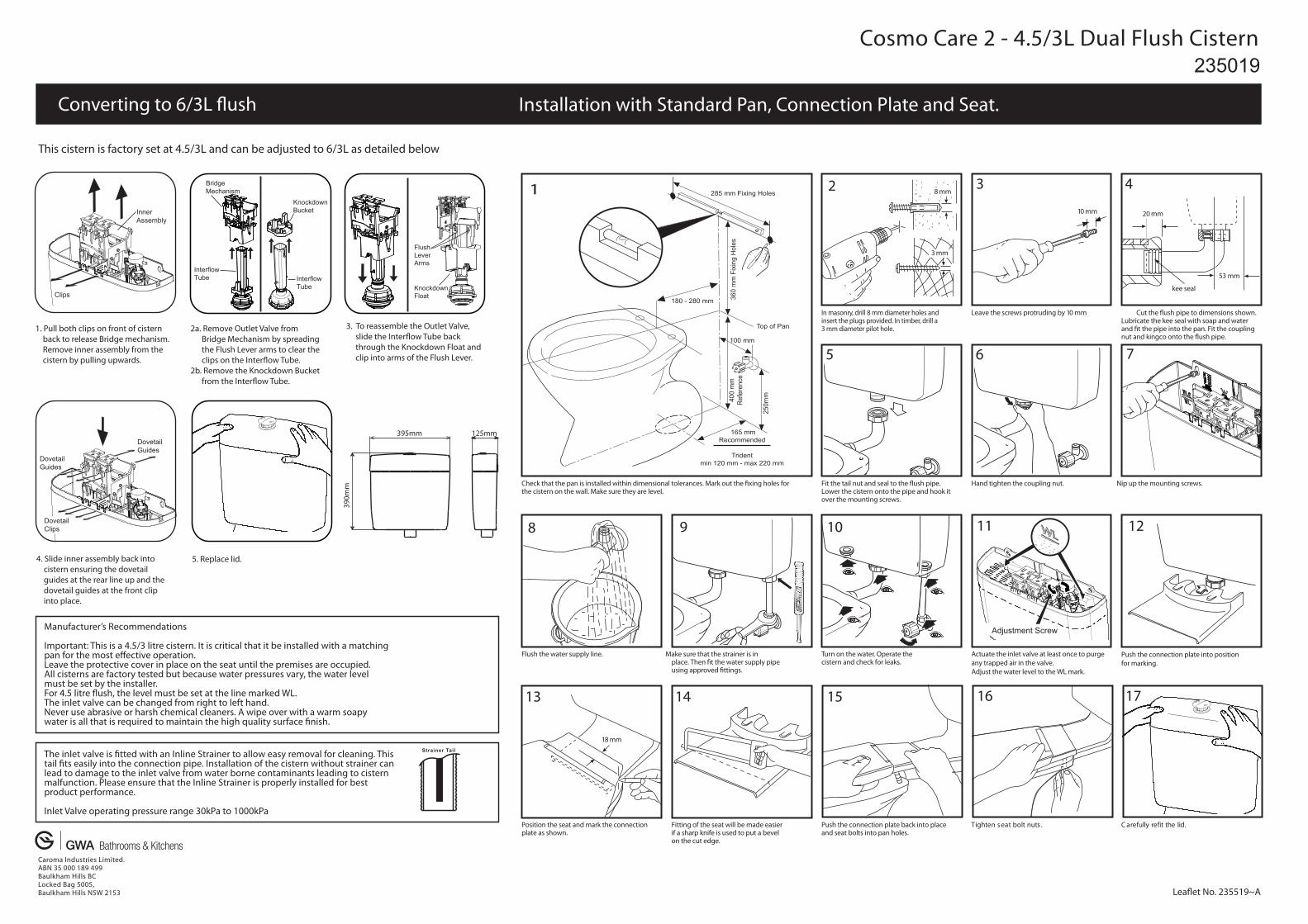
Cosmo Care 2 - 4.5/3L Dual Flush Cistern Converting to 6/3L flush Leaflet No. 235519~A 235019 Installation with Standard Pan, Connection Plate and Seat. This cistern is factory set at 4.5/3L and can be adjusted to 6/3L as detailed below 1. Pull both clips on front of cistern back to release Bridge mechanism. Remove inner assembly from the cistern by pulling upwards. 2a. Remove Outlet Valve from Bridge Mechanism by spreading the Flush Lever arms to clear the clips on the Interflow Tube. 2b. Remove the Knockdown Bucket from the Interflow Tube. 3. To reassemble the Outlet Valve, slide the Interflow Tube back through the Knockdown Float and clip into arms of the Flush Lever. 4. Slide inner assembly back into cistern ensuring the dovetail guides at the rear line up and the dovetail guides at the front clip into place. 2 3 4 5 6 7 8 9 10 11 12 13 14 15 16 17 5. Replace lid. Caroma Industries Limited. ABN 35 000 189 499 Baulkham Hills BC Locked Bag 5005, Baulkham Hills NSW 2153 The inlet valve is fitted with an Inline Strainer to allow easy removal for cleaning. This tail fits easily into the connection pipe. Installation of the cistern without strainer can lead to damage to the inlet valve from water borne contaminants leading to cistern malfunction. Please ensure that the Inline Strainer is properly installed for best product performance. Inlet Valve operating pressure range 30kPa to 1000kPa Strainer Tail Manufacturer’s Recommendations Important: This is a 4.5/3 litre cistern. It is critical that it be installed with a matching pan for the most effective operation. Leave the protective cover in place on the seat until the premises are occupied. All cisterns are factory tested but because water pressures vary, the water level must be set by the installer. For 4.5 litre flush, the level must be set at the line marked WL. The inlet valve can be changed from right to left hand. Never use abrasive or harsh chemical cleaners. A wipe over with a warm soapy water is all that is required to maintain the high quality surface finish. In masonry, drill 8 mm diameter holes and insert the plugs provided. In timber, drill a 3 mm diameter pilot hole. Leave the screws protruding by 10 mm Cut the flush pipe to dimensions shown. Lubricate the kee seal with soap and water and fit the pipe into the pan. Fit the coupling nut and kingco onto the flush pipe. Check that the pan is installed within dimensional tolerances. Mark out the fixing holes for the cistern on the wall. Make sure they are level. Fit the tail nut and seal to the flush pipe. Lower the cistern onto the pipe and hook it over the mounting screws. Hand tighten the coupling nut. Nip up the mounting screws. Flush the water supply line. Make sure that the strainer is in place. Then fit the water supply pipe using approved fittings. Turn on the water. Operate the cistern and check for leaks. Actuate the inlet valve at least once to purge any trapped air in the valve. Adjust the water level to the WL mark. Push the connection plate into position for marking. Position the seat and mark the connection plate as shown. Fitting of the seat will be made easier if a sharp knife is used to put a bevel on the cut edge. Push the connection plate back into place and seat bolts into pan holes. . d i l e h t t i f e r y l l u f e r a C . s t u n t l o b t a e s n e t h g i T 1 18 mm 20 mm 8 mm 10 mm 53 mm kee seal 3 mm Knockdown Float Flush Lever Arms Bridge Mechanism Knockdown Bucket Interflow Tube Interflow Tube Adjustment Screw 165 mm Recommended Trident min 120 mm - max 220 mm 285 mm Fixing Holes 180 - 280 mm Top of Pan 360 mm Fixing Holes 100 mm 250mm 400 mm Reference 390mm 395mm 125mm Dovetail Guides Dovetail Guides Dovetail Clips Inner Assembly Clips