IB 6.2.7.7-3I Rev. 0, Jan-99 INSTALLATION/MAINTENANCE INSTRUCTIONS Medium Voltage Vacuum Power Circuit Breakers VHK Model 20/21 VHKR Model 80 Model 21 ABB Power T&D Company, Inc. Distribution Systems Division
Transcript
IB 6.2.7.7-3IRev. 0, Jan-99
I N S T A L L A T I O N / M A I N T E N A N C E I N S T R U C T I O N S
Medium VoltageVacuum Power Circuit Breakers
VHK Model 20/21
VHKR Model 80
Model 21
ABB Power T&D Company, Inc.Distribution Systems Division
GENERAL.................................................................................................................... 4GENERAL INSPECTION................................................................................................. 5VACUUM INTERRUPTER EXAMINATION .......................................................................... 5BARRIER AND INSULATION INSPECTION ........................................................................ 5INSTALLING FRONT BARRIER ....................................................................................... 5MANUAL OPERATION FOR INSPECTION......................................................................... 5PADLOCK PROVISION .................................................................................................. 6INTERLOCKS ............................................................................................................... 6INSTALLING CIRCUIT BREAKER INTO COMPARTMENT .................................................... 8
CIRCUIT BREAKER REMOVAL - MODEL 21.............................................................. 8
REMOVAL FROM CONNECT POSITION ....................................................................... 8REMOVAL FROM TEST POSITION................................................................................ 9REMOVAL FROM DISCONNECT POSITION ................................................................. 9SAFE OPERATIONS RECOMMENDATIONS ...................................................................... 9
ADJUSTMENTS, TESTS AND PERIODIC MAINTENANCE........................................ 9
INSULATION CLEANING .............................................................................................. 10DC MILLIVOLT DROP TEST / MICRO-OHM TEST.......................................................... 10CONTACT WEAR AND CONTACT PRESSURE................................................................ 10CONTACT GAP .......................................................................................................... 10Contact Gap Check............................................................................................... 11CONTACT SEQUENCING............................................................................................. 11CLOSING AND OPENING TIMES .................................................................................. 12CLOSING AND OPENING SPEEDS................................................................................ 12Operating Mechanism .......................................................................................... 13Trip Latch Engagement (Bite).............................................................................. 13CONTROL DEVICE ..................................................................................................... 13CLOSE LATCH ROD RELEASE TRAVEL ....................................................................... 14LUBRICATION ............................................................................................................ 13DIELECTRIC TESTS.................................................................................................... 13
ELECTRICAL CHARACTERISTICS OF CONTROL DEVICES ................................ 14
DC AND AC CLOSING OPERATING SEQUENCE ........................................................... 15AC CLOSING OPERATING SEQUENCE ........................................................................ 15
GROUND AND TEST DEVICES ................................................................................. 17
FIGURE A1 - ...CIRCUIT BREAKER ASSEMBLY WITH LIFTING YOKE INSTALLED .................... 18FIGURE A2 - CIRCUIT BREAKER REAR - MODEL 21 ......................................................... 19FIGURE A3 - FRONT CIRCUIT BREAKER PANEL - MODEL 21 ............................................ 20FIGURE A4 - FRONT CIRCUIT BREAKER PANEL - MODEL 30 ............................................ 21FIGURE A5 - MANUAL CHARGING OF ELECTRICALLY OPERATED CIRCUIT BREAKERS ....... 22FIGURE A6 - RACKING MECHANISM & INTERLOCKS......................................................... 23FIGURE A7 - RACKING MECHANISM - FINAL ADJUSTMENT ............................................... 24FIGURE A8 - METHOD OF RACKING CIRCUIT BREAKER .................................................... 25FIGURE A9 - CONTACT PRESSURE (MODELS 21 AND 80)................................................. 26FIGURE A10 - TRIP LATCH ENGAGEMENT ADJUSTMENT .................................................... 27FIGURE A11 - CONTROL DEVICE ADJUSTMENT ................................................................. 28FIGURE A12 - TYPICAL DC SCHEMATIC OF CONTROL CIRCUIT .......................................... 29FIGURE A13 - TYPICAL AC SCHEMATIC OF CONTROL CIRCUIT........................................... 30TABLE A1 - CONTROL CIRCUIT OPERATING VOLTAGE RANGE ........................................ 31TABLE A2 - CONTROL CIRCUIT TYPICAL CURRENT VALUES............................................ 31TABLE A3 - VHK OPERATING PARAMETERS.................................................................. 32
These instructions do not purport to cover all details or variations nor to provide for every possiblecontingency to be met in connection with installation, operation, or maintenance. Should furtherinformation be desired or should particular problems arise which are not covered sufficiently for thepurchaser’s purpose the matter should be referred to the nearest District Office or send E-mail to:[email protected].
IB 6.2.7.7-34
INTRODUCTION
This manual contains instructions for inspection,application, installation, operation, testing,adjustment and maintenance of all VHK Model20/21 and VHKR Model 80 vacuum power circuitbreakers. Use of these instructions will facilitateproper application and maintenance of the circuitbreaker and prolong its life and usefulness.
The specific ratings for each breaker are locatedon each Breaker Nameplate.
Throughout this manual, there are three terms thatmust be heeded.
CAUTIONNot adhering to these instructions can result indamage to the breaker.
WARNINGNot adhering to these instructions can result inpersonal injury or DEATH, and damage to thebreaker.
DANGERNot adhering to these instructions will result inpersonal injury or DEATH, and permanent damageto the breaker and other equipment.
RECEIVING AND STORAGE
Immediately upon receipt of the circuit breaker,examine it to determine if any damage or loss wassustained during transit. If abuse or incorrecthandling is evident, file a damage claim at oncewith the carrier and promptly notify the nearestDistrict Office. The company is not responsible fordamage of goods after delivery to the carrier. Wewill, however, lend assistance if notified of claims.
Unpack the circuit breaker as soon as possibleafter receipt. If unpacking is delayed, difficultymay be experienced in making a claim fordamages not evident upon receipt. Use careduring unpacking in order to avoid damaging anyof the circuit breaker parts. Check the contents ofeach device against the packing list before
discarding any packing material. If any shortageof material is discovered, promptly notify thenearest District Office. Information specifying thepurchase order number, device serial numbersand part numbers of the damaged or missingparts should accompany the claim.
The circuit breaker should be installed in itspermanent location as soon as possible. If thebreaker is not to placed into service for some time,it is advisable to provide some means ofprotection. This may be done by keeping thebreaker in its original shipping crate and storing itin a warm, dry, uncontaminated atmosphere. Ifthe breaker cannot be stored properly due tocircumstances beyond your control, it must bethoroughly checked before being put into service.This is to insure it has not absorbed any moisture,or has become rusted or generally contaminatedin any way.
INSTALLATION
General
Prior to installation of the circuit breaker into thecompartment, certain preliminary inspectionsshould be made to insure proper operation. Thissection lists the recommended inspectionprocedures.
ABB VHK vacuum circuit breakers are shipped withthe contacts closed, Closing Springs dischargedand Opening Springs charged. This is to protectagainst the possibility of the contacts striking theinside of the vacuum interrupter enclosure anddamaging themselves during shipping.
WARNINGPrior to any disassembly or inspection of the circuitbreaker, the closing springs must be discharged,and the breaker should be open. Failing to do socould result in personal injury.
If the circuit breaker is equipped with anUndervoltage Trip Device (a.k.a., UVTD), theRetaining Strap applied to the UVTD at the factorymust be removed. The Retaining Strap wasapplied to hold the Armature of the UVTD in theenergized position so the breaker could be closed.
IB 6.2.7.7-3I5
If the Retaining Strap is not removed, the UVTDwill not be able to trip the breaker.
If it is necessary to raise or move the breaker,attach a lifting yoke to the truck or a fifth wheel totransport the breaker as required. See Figure A1in the Appendix.
General Inspection
Inspect the condition of the circuit breaker vacuuminterrupters and electrical connections prior toinstalling the circuit breaker into the compartment.Even though each circuit breaker is completelyadjusted and tested at the factory, shipping andhandling conditions, and/or incorrect storage couldcause defects.
The front cover and barrier assembly (Figure A3or A4) must be removed for access to andinspection of the vacuum interrupters and theirassociated adjustments.
Vacuum Interrupter Examination
WARNINGIf the circuit breaker has been energized, or it isunsure if the circuit breaker has ever beenenergized, the mid-band ring (on vacuuminterrupters so equipped) must first be dischargedbefore any work is performed on or near theinterrupters. A grounding stick must be used todischarge the ring by fastening the ground cable ofthe stick to a known ground and touching thegrounding tip of the stick to each mid-band ring.
The insulated vacuum container should beexamined carefully for cracks in the area of themetal-to-insulation interface seals on both endsand around the Mid-Band Ring. Since a certainamount of transmitted light is usually required todetect cracks, the inspection should be done in awell lighted area. If the mid-band ring, when soequipped, has been bent by accidental impact,that area should be specially scrutinized for sealdamage. Small external chips will not impair theuseful life of the interrupter.
Barrier and Insulation Inspection
All barriers and insulated parts should be checkedfor damage. Any dust or dirt should be removed
by compressed air or with a clean lint-free cloth. Ifthese parts have become contaminated with anyheavy dirt or grease, a clean, lintless clothsaturated with alcohol should be used.
The lead support moldings are polyester glass andoccasionally have some resin rich cracks orcrazing that develops. These do not indicatedefective material and should not cause concern.
Installing Front Barrier
Install the assembly and fasten with four lowerfront barrier screws and one screw on each side,inside the front barrier.
Note: It is recommended that a dielectricwithstand test be performed prior to initially puttingthis or any type vacuum circuit breaker intoservice. Refer to "Dielectric Tests" in the"Adjustments, Tests and Periodic Maintenance"section for the correct test procedure.
Manual Operation For Inspection
The electrically operated circuit breakers can becharged manually with a removable ManualCharge Handle for bench tests or emergencyoperation. The removable Manual Charge Handleis an accessory and is supplied only whenordered.
Position the handle onto the Manual ChargingLever hooked section in the long slot on the PawlCarrier (See Figure A5 in the Appendix). Thesmall tabs on the Manual Charging Handle will fitin the small holes of the Pawl Carrier. Push downon the Manual Charging Handle until it will nottravel any further. This partially charges theClosing Springs. Repeat this operation until thecharging mechanism is heard to snap over center(approximately 10 operations), and the SpringIndicator clearly shows the message SPRINGSCHARGED. The circuit breaker can now beclosed by pulling out on the Manual Close Lever.The Circuit Breaker can then be closed bypressing the Manual Trip Button. See Figures A3and A4 in the Appendix.
IB 6.2.7.7-36
Padlock Hasp Provision
Refer to Figure A6 located in the Appendix. TheRacking Mechanism Padlock Hasp provisionpermits the breaker to be padlocked in theDISCONNECT and TEST positions. Thisprovision is accomplished by the Padlock Haspblocking the Blocking Lever attached to theRacking Release Assembly, preventing the RackScrew from being rotated clockwise to the releaseposition. If not functioning properly, the AdjustableLink must be adjusted as follows.
1. Remove the lower Front Panel of thebreaker.
2. Remove the Retaining Ring from one of
the pins securing the Adjustable Link. 3. Rotate the free end of the Adjustable Link
to vary its length, so that whenreconnected to the pin, the padlockfunctions as noted above.
4. Replace the Retainer. 5. This adjustment might effect feature "D" of
the "Interlocks (Racking Mechanism)",below, and it should be checked also.
NOTE: As a special option, the breaker may beordered with Three-Position Padlocking, whichalso permits the breaker to be padlocked in theCONNECT position.
Interlocks (Racking Mechanism)
The four mechanical interlocks that work inconjunction with the Racking Mechanism toprotect both user and breaker should function asspecified below. If malfunction is identified andthe recommended adjustments do not correct theproblems consult the factory before placing thebreaker in service.
Refer to the next sections "Installing CircuitBreaker Into Compartment" and "Removing CircuitBreaker" for a complete description of the RackingMechanism components and operation.
A. When in the WITHDRAW position, theClosing Springs will discharge automatically.If the Closing Springs have been previouslycharged, they will discharge when the rackingmechanism reaches this position. This isaccomplished by a linkage, activated by anAdjusting Screw on a welded tab at the centerof the Rack Shaft. This pulls the DischargeLink Assembly which releases the Close Latchto its unlatched position. If the interlock doesnot function as specified, adjust as follows:
1. Make sure Racking Mechanism is in theDISCONNECT position.
2. Following the instructions in "Removal
from DISCONNECT Position," rotate theRack Screw counterclockwise. TheManual Close Lever should begin movingafter one-half (1/2) turn from theDISCONNECT position.
3. If the Manual Close Lever requires more
than one-half (1/2) turn to begin moving,then adjustment of the Adjusting Screw onthe Racking Shaft will have to be made.The gap between the Adjusting Screw andthe Discharge Link Assembly is between0.010” – 0.031”. See Figure A7 in theAppendix.
B. The Rack Screw cannot be turned to move the
breaker starting from the DISCONNECT,TEST and CONNECT positions, unless theRelease Lever is first operated. A finger in theIndex Lever engages one of three holes in theRack Screw corresponding to each of thepreviously mentioned positions, preventing itfrom rotating. Turning the Release Lever tothe left disengages the finger from the hole,allowing the Rack Screw to be rotated.
1. If the Rack Screw can be rotated withoutturning the Release Lever, check if theRelease Lever is jammed in the left(release) position. If so, see if it can befreed.
2. Visually inspect that the finger of the Index
Lever is engaging in the correspondinghole in the Rack Screw.
IB 6.2.7.7-3I7
NOTE: If the Release Lever cannot be turned tothe left, make sure breaker is first in the Openposition.
C. The Release Lever cannot be operated whenthe breaker is in the closed position. Thisprevents connecting or disconnecting thebreaker from the Primary Stabs in thecompartment with the breaker closed. ARacking Lock Bracket, operated by thebreaker’s Jackshaft, blocks the Index Leverwhen the Jackshaft is in the closed position. Ifthe interlock is not functioning as noted,perform the following inspections. Refer toFigure A6 in the Appendix.
1. Check that the Racking Lock Bracket isconnected to the Jackshaft via a Link. Ifnot connected then reconnect.
NOTE: The Operations Counter and theOpen/Closed Indicator are also driven by thesame Racking Lock Bracket.
2. Check that nothing in the Racking
Mechanism is bent.
D. When the circuit breaker is between theWITHDRAW, DISCONNECT, TEST andCONNECT positions, any attempt to close thebreaker will discharge the Closing Springs,and the contacts will not close. This is referredto as "Trip Free" operation. The finger of theIndex Lever rides on the circumference of theRack Screw, holding the Release Lever in itsreleased position. A linkage between theRelease Lever and Trip Latch then holds theTrip Latch in its unlatched position. If thisinterlock is not functioning as noted, performthe following:
1. Confirm that the Trip Latches are properlyadjusted and functioning. Position theRack Screw so the Rack Mechanism is inthe DISCONNECT, TEST or CONNECTposition. Charge and Close the breaker,and then press the Manual Trip Button.
NOTE: If the breaker does not trip the Trip
Latch and/or linkage is at fault. Contactthe Customer Service Center forassistance.
NOTE: When the Racking Mechanism isbetween the WITHDRAW, DISCONNECT,TEST, or CONNECT positions the ManualTrip Button should have a slight amount ofplay so as not to “Bottom Out”. TheAdjustable Link and the Link to Trip Lever(See Figure A6 in the Appendix) both can beadjusted to accomplish this. Adjustment is asfollows: 1. If adjustment is necessary, the “Link to
Trip Lever” should be adjusted first to getthe slight play in the Trip Linkage.
2. If necessary, the Adjustable Link can beadjusted after first removing one of thesecuring Retainer Rings.
3. The interlock should now be properlyadjusted. Confirm by retesting theinterlock.
4. If the interlock is now functioning properly,
replace the retainer removed in step 2.
5. If the Adjustable Link setting is changed,the Padlock Hasp Provision in theprevious section will have to rechecked forproper operation.
Installing Circuit Breaker Into Compartment(See Figure A8 in the Appendix) NOTE: Model 80 breakers do not have RackingMechanisms. They are bolted-in units. NOTE: CLOCKWISE rotation of racking crank forinserting breaker. COUNTERCLOCKWISErotation of racking crank for removal of breaker. 1. Turn Motor Disconnect Switch (if so equipped)
to the OFF position. Refer to Figures A3 andA4 in the Appendix.
NOTE: Step 2 is possible only if RackingMechanism is in CONNECT, TEST orDISCONNECT positions, and the breaker isOpen)
2. Make sure the Racking Mechanism is in theWITHDRAW position. This can be done byfirst turning the Release Lever to the left.While holding the Release Lever to the left,engage the Racking Crank (accessory) into
IB 6.2.7.7-38
the Rack Screw and rotate crankcounterclockwise until a definite resistance isfelt (Do Not Force).
NOTE: If the Index Lever is observed (and/orheard, by a "click" sound) to instead engage inone of the holes of the Rack Screw, causing theRelease Lever to turn back to the right, theRacking Mechanism is still not in theWITHDRAW position. Step 2 must be repeated.
NOTE: If the Closing Springs were previouslycharged, they will automatically discharge whenthe Racking Mechanism reaches theWITHDRAW position.
3. Engage the Fifth Wheel accessory into theHole Guide in the breaker’s truck. See FigureA1 in the Appendix. Push the circuit breakerinto the switchgear compartment until adefinite stop is felt. This stop is the rollers ofthe breaker’s Racking Arms hitting the backedge of the Racking Ports of thecompartment.
4. Turn the Release Lever to the left, engage
Racking Crank into the Rack Screw, androtate Crank clockwise until rackingmechanism automatically stops at theDISCONNECT position. The breaker is nowheld captive in the compartment by the rollersof the Racking Arms and the Racking Ports ofthe compartment.
5. To rack the circuit breaker to TEST position,turn the Release Lever to the left, turn Crankclockwise one-quarter (¼) turn, and thenrelease the Release Lever. It will remain inthe released position. Continue crankingclockwise until the racking mechanismautomatically stops at the TEST position.
6. With the circuit breaker now in the TESTposition, turn the Motor Disconnect Switch tothe ON position to electrically charge theClosing Springs. If a Motor Disconnect Switchwas not provided, the Closing Springs willautomatically charge when the breakerapproaches the TEST position.
Check for proper operation by closing andopening (tripping) the circuit breaker bothelectrically and mechanically. This includescontrol switches, relays, etc.
WARNINGFor safety, when racking the circuit breaker "to" or"from" the CONNECT position, the compartmentdoor must be closed, and the racking crankinserted through the opening provided in thecompartment door.
7. To rack circuit breaker to the CONNECTposition, close the compartment door, andreinsert the crank into the Racking Screw viathe Access Door in the compartment door.See Figure A8.
8. Turn the Release Lever to the left, rotate Crank
clockwise one-quarter (¼) turn, and thenrelease the Release Lever. It will remain in thereleased position. Continue cranking clockwiseuntil the Racking Mechanism automaticallystops at the CONNECT position.
CAUTIONDo not attempt to rack circuit breaker any further,damage to the racking mechanism may result.
CIRCUIT BREAKER REMOVAL(MODEL 21)
Removal From CONNECT Position
WARNINGFor safety, when racking the circuit breaker "to" or"from" the CONNECT position, the compartmentdoor must be closed, and the racking crankinserted through the opening provided in thecompartment door.
1. Open Access Door in the front compartmentdoor, and engage Racking Crank into theRack Screw. See Figure A8.
2. Turn the Release Lever to the left, rotate the
Crank counterclockwise one-quarter (¼) turn,and then release the Release Lever. It willremain in the released position. Continuerotating the crank counterclockwise until theRacking Mechanism automatically stops at theTEST position.
IB 6.2.7.7-3I9
Removal From TEST Position
1. Turn the Release Lever to the left, rotate theCrank one-quarter (¼) turn counterclockwise,and then release the Release Lever. It willagain remain in the released position.Continue Cranking counterclockwise untilRacking Mechanism automatically stops at theDISCONNECT position.
Removal From DISCONNECT Position
1. Turn the Rack Release Lever to the left, andturn Crank counterclockwise one-quarter (¼)-turn. Release the Rack Release Lever. It willagain remain in the released position.Continue cranking counterclockwise until aresistance is felt (approximately 2-3 turns) (DoNot Force.) The breaker is now in theWITHDRAW position.
If the Closing Springs were previouslycharged, they will automatically discharge asthe Racking Mechanism reaches theWITHDRAW position.
2. The circuit breaker can now be removed from
the compartment by pulling on the handlelocated on the Front Barrier.
Safe Operations Recommendations
It is recommended that any circuit breaker bewithdrawn and stored in the withdrawn positionwhenever it is to be maintained in the OPENposition with no planned switching.
It is recommended that a Ground & Test Device(a.k.a. G&T Device) be connected to the propercompartment when any work is to be done on anybus or feeder circuit. See section "Ground andTest Devices" for a description.
ADJUSTMENTS, TESTS ANDPERIODIC MAINTENANCE
The circuit breakers are designed and tested toinsure minimum maintenance. The fewadjustments that are noted are required only when
an operational check indicates a problem. Ofcourse, during the maintenance checks, allaccessible bolts, units and screws should beroutinely checked to insure that they are tight.
It is recommended that the circuit breaker beinspected after the first 1000 mechanicaloperations and on a yearly basis unlessenvironmental considerations and operatingexperience indicate that more or less frequentinspections are appropriate.
Vacuum interrupters, as used on the VHK vacuumcircuit breakers, have an inherently long contactlife and will provide trouble-free service undervaried application conditions as long as the circuitbreaker is applied within its rating. Theinterrupters have been tested up to 2000% KSIminimum. It is unlikely that a circuit breaker willbe subjected to this much duty in its life, and it isnot expected that the interrupters will have to bereplaced due to excessive contact erosion.
The wear condition of the individual vacuuminterrupters will vary, however, depending oncircuit conditions and such variables as singlephase versus three-phase interruption, X/R ratio(asymmetry) and relay delay times. Therefore, theinterrupters in all three phases may not erodeequally. Additionally, interrupting high short-circuitcurrent will cause contact erosion to occur fasterthan load current interruptions.
There is, however, a check for Contact Wipe(Contact Spring overtravel), which is a measure ofcontact erosion. This check is covered under thesubsection "Contact Wear and Contact Pressure."When Contact Wipe is less then the minimumspecified and there is not any mechanicalproblem, the interrupter should be replaced due tocontact erosion.
If, after the first inspection period, there is noindication of any problems, actual operatingexperience with specific circuits will indicate thefuture amount of maintenance needed for thevarious circuit breakers, and the procedure can bemodified as required.
Where unusual service conditions exist, ascovered by ANSI Standard C37.04, it must bepresumed that these conditions were consideredat the time of order, the equipment supplied was
IB 6.2.7.7-310
designed for special application, and anappropriate supplemental maintenance programhas been developed. These maintenanceinstructions only cover circuit breakers used underthe standard service conditions.
At the selected maintenance period, the followingmaintenance, tests and adjustments (if necessary)should be made:
Insulation Cleaning
WARNINGIf the circuit breaker has been energized, or it isunsure if the circuit breaker has ever beenenergized, the mid-band ring (on vacuuminterrupters so equipped) must first be dischargedbefore any work is performed on or near theinterrupters. A grounding stick must be used todischarge the ring by fastening the ground cable ofthe stick to a known ground, and touching thegrounding tip of the stick to each mid-band ring.
Any dirt, dust or grease should be removed fromthe surfaces of the entire current carrying structureand vacuum interrupter. Wiping the surface with aclean, lint-free cloth is normally sufficient. If thereis heavy grease, alcohol should be used.
DC Millivolt Drop Test / Micro-ohm Test
During maintenance periods, the condition of thebreaker current circuit can easily be determined byperforming a Millivolt Drop Test or a Micro-ohmtest. This test should be performed regardless ofwhether the circuit breaker had interrupted low orhigh currents, or has minimum operations.
NOTE: The values for resistance, given in TableA3, are for new breakers. It is normal andacceptable for a used breaker to have resistancevalues as much as 100% greater than thesevalues.
Refer to Table A3 in the Appendix for the Millivoltdrop and Resistance values for the circuitbreakers covered, from lead to lead. If thePrimary Disconnects (a.k.a., Tulips) are to beincluded in the test path, a 2.000" ± 0.005"diameter smooth (62rms) copper conductor mustbe inserted into the open end of each PrimaryDisconnect to achieve the proper contactpressure.
Contact Wear and Contact Pressure(Contact Wipe)
The amount of contact wear can be determined bymeasuring what is referred to as Contact Wipe (orovertravel). This can be accomplished by closingthe breaker and carefully measuring the gapbetween the Nut and the Trunion Block of theContact Spring Assembly. See Figure A9 in theAppendix.
WARNINGKeep hands clear of all moving parts. Seriousinjuries can result if a person comes in contact withbreaker parts when the breaker is being opened orclosed, or closing springs are being charged ordischarged. Use extension tools for manipulatingbreaker parts.
This adjustment is initially set at the factory to arange of 0.093 - 0.101 (2.4mm – 2.6mm). As thebreaker sees service and the contacts start toerode, this value will decrease. Asymmetrical andsingle phase interruption will cause contacterosion and wipe deterioration to occur differentlyfor all three poles. Once the Wipe has decreasedto 0.031" and it is determined that the breaker isoperating properly, the interrupter assembly willneed replacement. The measurement is made asfollows:
1. Close the breaker and measure between theNut and Spring Base. See Figure A9.
2. The gap should be in the range shown inTable A3.
3. When the Contact Wipe is less than 0.031”,and it has been determined that the breakercloses fully, and there is not a mechanicalproblem than the Interrupter should bereplaced due to contact erosion.
Contact Gap
Upon opening the breaker, the resulting gapbetween the vacuum interrupter contacts isreferred to as Contact Gap. This gap is also thedistance the contacts travel upon closing. Thiscan range from a minimum of 0.310 " (7.9mm) ona new breaker, to a maximum of 0.540" (13.5mm)
IB 6.2.7.7-3I11
on a used breaker with an interrupter nearingreplacement. As the breaker sees service, andthe contacts start to erode, this value will increase.
The following procedure describes how todetermine the Contact Gap. The necessary toolsare: an ink pad and a thin flat straight edge withapproximate dimensions should in Figure A9 inthe Appendix. Proceed with the circuit breakerwithdrawn from the compartment.
WARNINGIf the circuit breaker has been energized, or it isunsure if the circuit breaker has ever beenenergized, the mid-band ring (on vacuuminterrupters so equipped) must first be dischargedbefore any work is performed on or near theinterrupters. A grounding stick must be used todischarge the ring by fastening the ground cable ofthe stick to known ground, and touching thegrounding tip of the stick to each mid-band ring.
Contact Gap Check (See Figure A9).
1. Open the breaker and discharge theclosing springs.
2. The Racking Mechanism must be in either
the DISCONNECT, TEST or CONNECTposition.
3. Apply ink from the Ink Pad to the end ofthe Straight Edge.
4. Slide the Straight Edge along the bottomof the Molded Chair Assembly until theStraight Edge contacts the Pushrod. Thiswill be the first of two markings needed.See Figure A9.
5. Close the breaker and repeat Steps 3 and4.
6. The Gap is the distance measured
between the two lines. The acceptablelimits are listed in Table A3, located in theAppendix.
Contact Sequencing (Synchronization)
Before checking contact sequence, verify that theContact Wipe and Gap for each pole is correct.Refer to the subsections "Contact Wipe" and
"Contact Gap". It is not expected that the contactsequence should exceed the 4 millisecond limit,therefore, before attempting to readjust, verify thatthe test equipment and procedure are correct.Also consider, especially when testing withelectronic equipment, that multiple 2 millisecondvacuum interrupter contact bounces arepermissible during normal closing, and thesebounces can influence the contact timemeasurements. If there are any questions,consult the factory.
If it is determined that the contact sequence is notwithin 4 milliseconds, adjustment is required.Usually, readjustment of one pole should besufficient so that all three poles touch within 4milliseconds. The gap of the pole to be changedshould be decreased if the contacts of that poleare touching after the other two poles, orincreased if the contacts are touching before theother two poles. The gap is decreased by turningthe Pushrod clockwise, and increased by turningthe Pushrod counterclockwise, as viewed from thetop of the breaker.
WARNINGKeep hands clear of all moving parts. Seriousinjuries can result if a person comes in contact withbreaker parts when the breaker is being opened orclosed, or closing springs are being charged ordischarged. Use extension tools for manipulatingbreaker parts.
Before the Pushrod can be turned, the breakermust be in the Open position, Closing Springsdischarged and the Pushrod Pin removed. SeeFigure A9 in the Appendix. With the breakerOpen, the vacuum in the interrupter maintains aconstant upward force of approximately 25 poundson the moving contact and Pushrod. Therefore,before removing pin, the contact must be helddown in the open position by temporary spacers.After removing the Retaining Ring and PushrodPin, rotate Pushrod as required.
One quarter (1/4) turn of the Pushrod will changethe gap by approximately 0.019" (0.5mm). Afterrotating the pushrod, carefully reposition itvertically to align the holes and the stud. Replacethe pin and retainer and remove the temporaryspacer. During the readjustment procedure, notethat the Contact Wipe and Contact Gapdimensions must be maintained. The Contact
IB 6.2.7.7-312
Gap and Contact Wipe are inversely related;increasing one decreases the other, and visa-versa. Also, note that no more than one-half (1/2)turn should be required when readjusting forcontact sequence.
After completing the contact sequence procedure,recheck the Contact Wipe and gap for each pole.If the specified Contact Gap, Contact Wipe andcontact sequencing cannot all be obtained, and itis determined that the breaker is operatingproperly, the interrupter is in need of replacement.
The front cover and interphase barrier assemblycan now be reinstalled. Return the rack screw toits original position by turning it counterclockwiseapproximately two to three turns until it stops.
Closing and Opening Times
After the operation intervals, it is recommendedthat the Closing and Cpening Times be checked.This can be done by use of a cycle counter, travelrecorder or oscillograph to monitor the time fromcoil energizing to contact kiss (closing) or part(opening).
Note: Normally, the Closing Time is not critical.The breaker performance is satisfactory if theClosing Speed, Opening Speed and OpeningTime are within specification. See Table A3 in theAppendix for the nominal values for theseparameters.
The circuit breaker closing and opening timesshould be within the time ranges for normaloperation. Note the following:
• Times are from signal initiation to primarycontact kiss (make) or break.
• Times for DC controls supplied by a rectified
unconditioned power source, and all ACcontrols, may wander by as much as ±4msdue to the "current-zeroes" associated withsuch currents.
• Below 0°C, the closing times will increase
(but with no reduction in closing force), andopening times will usually be within thelimits.
• Adjustments to correct times, if found to be
outside limits, are critical and the nearestDistrict Office should be contacted forrecommendations.
Closing and Opening Speeds
The Closing and Opening speeds of the PrimaryContacts can be determined by use of a travelrecorder, which records their linear travel versustime. The output can be fed into a travel recorderor oscilloscope.
Before the Closing and Opening speeds arechecked, the Contact Wipe should first beinspected. This is because, in addition to theenergy provided by The Opening Springs, theContact Springs provide additional accelerationenergy through the wipe distance upon contactpart. As the Primary Contacts erode, the ContactWipe decreases, and the opening speed willdecrease. Speed should still be withinacceptable limits if the wipe is still within limits.Refer to Table A3 in the Appendix.
WARNINGDo not attempt to increase the opening speed byreadjusting the push rod to gain more contact wipe.
If either of the speeds is too slow, and the ContactWipe is within the limits specified, examine thebreaker for any moving parts that appear to bebinding. If none can be found, consult the factoryfor assistance.
Operating Mechanism
Trip Latch Engagement (Bite) (See FigureA10).
The Latch Engagement Adjusting Screw (3) islocated at the right of the right-hand mechanismhousing (1). It can be reached easily from the topof the breaker, after removal of the top coverplate.
To adjust the Latch (2) Engagement, proceed asfollows:
IB 6.2.7.7-3I13
1. Back off Adjusting Screw (3) to assureexcessive latch engagement.
2. Close the circuit breaker.
3. Turn Adjusting Screw (3) down slowly until theLatch just releases, tripping the circuitbreaker.
4. Back off the Adjusting Screw (3) 2 turns.
WARNINGKeep hands clear of all moving parts. Seriousinjuries can result if a person comes in contact withbreaker parts when the breaker is being opened orclosed, or closing springs are being charged ordischarged. Use extension tools for manipulatingbreaker parts.
Control Device (See Figure A11)
The Control Device is adjusted before leaving thefactory. It is recommended that no attempt bemade to adjust the internal relays and contacts ofthis device in the field. If replacement of theControl Device is required, the Close LatchRelease Rod (5) overtravel may be adjusted asdescribed below.
Close Latch Rod Release Overtravel
1. Back off on Close Latch Release Rod (5) andcheck that the circuit breaker will not closeelectronically or manually by pushing up onthe Close Latch Release Rod to the fullextent of its travel.
2. Charge the Closing Springs. Push up theClose Latch Release Rod to the full extent ofits travel and hold.
3. While holding the Close Latch Release Rodin this position, turn up on the Close LatchRelease Rod until the circuit breaker closes.Turn the Close Latch Release Rod up anadditional 1-1/2 turns.
Lubrication
All mechanism parts, bearings, pins etc. of theVHK vacuum circuit breakers have beenlubricated with Anderol 757 during factory
assembly. While any adjustments, tests and/orperiodic maintenance is being performed, it isrecommended that the grease for those parts beexamined.
If the grease should become contaminated orunduly oxidized (hardened and darkened), or ifparts are replaced, any relubrication should bedone with the same lubricant, available from ABBas part number 712994-C00 (1 LB can).
Note the following:
• The mechanism should be periodically inspectedfor lubrication contamination. The frequency ofinspection is dependent upon experience withthe operating environment.
• Anderol is a Lithium soap-based syntheticlubricant. Anderol is not compatible with manyother lubricants. Mixing with other incompatiblelubricants will cause caking and discolorationand will require complete purging andrelubrication of breaker parts.
• Do not apply grease to latch or roller surfaces. • Do not use light oil to lubricate any mechanism
parts. In emergency situations, Anderol 732 maybe used as a temporary lubricant, if adequatetime (several hours) is allowed for the solvents toevaporate prior to any mechanical operations. Itis mandatory that the breaker undergo thoroughlubrication with Anderol 757 as soon as possible.Note that bearing surfaces must be repacked,requiring disassembly of the mechanism. Do notoperate the circuit breaker without completingthis procedure.
• Use of solvents to free contaminated lubricant is
strictly forbidden without immediate relubricationusing Anderol 757.
• The charging motor has sealed bearings. No
lubrication is required.
Dielectric Tests
It is recommended that dielectric withstand testsbe made prior to use and at routine maintenanceperiods to verify the integrity of vacuum circuitbreakers. If, during the dielectric withstand test,
IB 6.2.7.7-314
the required test voltage cannot be sustainedacross the open contacts of the vacuuminterrupter, the interrupter may be faulty and mustbe replaced. Always insure that the contact airgap is correct before conducting primary circuitdielectric tests.
WARNINGDo not run any primary circuit dielectric withstandtests on isolated interrupters with open contactsabove rated voltage, unless test personnel areadequately shielded or are no less than six feetfrom the test unit.
WARNINGIf the circuit breaker has been energized, or it isunsure if the circuit breaker has ever beenenergized, the mid-band ring (on vacuuminterrupters so equipped) must first be dischargedbefore any work is performed on or near theinterrupters. A grounding stick must be used todischarge the ring by fastening the ground cable ofthe stick to known ground, and touching thegrounding tip of the stick to each mid-band ring.
Note the following:
• Dielectric test voltages higher than rated voltage,
applied across open contacts, may cause avacuum interrupter to emit some X-radiation,which could be a health hazard on prolongedexposure at close range. Accordingly, eventhough the emission is low, it is consideredappropriate to exercise caution. Therefore, donot run any primary circuit dielectric withstandtests on isolated interrupters with open contactsabove rated voltage unless test personnel areadequately shielded or they are no less than sixfeet from the test unit.
• It is to be noted that no hazardous X-radiation isproduced with closed contacts at any testvoltage, nor with open contacts at rated voltage,and there should be no cause for concern. Ifthe breaker is tested in its compartment at thetest voltages recommended below, the steelenclosure will provide sufficient shielding toprotect personnel from X-radiation at the normaldistances maintained for electrical safety.
NOTE: Only an AC hi-pot test is recognized as avalid test. DC, Meggers, etc. are not valid for hi-pot testing.
The following test values should be used fordielectric testing the new breaker, and are to beapplied for a one-minute period:
• Primary Circuit, new interrupters36kV for 7.5kV and 15kV19kV for 5kV
Once in service, the different circuits should betested at 75% of these ratings.
If it is desired to make a dielectric test on thesecondary control wiring, turn the spring chargingMotor Disconnect Switch to the "OFF" position.Apply test voltage (1100VAC) for one minute toeach of the secondary contacts of the circuitbreaker.
If it is desired to make a dielectric test on thespring charging motor, turn the Motor DisconnectSwitch to the "ON" position. Apply test voltage(540VAC) for one minute to the motor circuit.
IB 6.2.7.7-3I15
ELECTRICAL CHARACTERISTICS OFCONTROL DEVICES - (REFER TOFIGURES A12 AND A13 IN THEAPPENDIX)
NOTE: The charging time of the breaker with thenew Ryobi Motors is approximately four seconds.
For operating voltage ranges and normal currentdraw for various nominal control voltages, refer toTables A1 and A2 in the Appendix. The currentvalues given are average steady state values.Momentary inrush currents for all charging motorsand coils are approximately three times thesevalues.
Please refer to the specific schematic diagramsand other operational information furnished withyour order. Typical schematics for generalelectrical information can be found in theAppendix.
DC and AC Closing Operating Sequence
With the circuit breaker open, closing springsdischarged, control power source energized, andmotor disconnect switch to ON position, operationoccurs as follows:
1. Immediately upon the availability of controlpower across disconnects "5" and "02", thespring charging motor is energized, which inturn charges the closing springs. When theclosing springs are charged, limit switchcontact "LSb" is opened, and limit switchcontact "LSa" is closed.
2. Operation of the close control switch (with its
power source), connected to disconnects "03"or "7" and disconnect "6", energizes the latchrelease coil (X) through the circuit breakerauxiliary switch "b" contact, the normallyclosed lockout relay contact "Yb", limit switchcontact "LSa". The latch release coil (X)releases the closing latch. The springs thendischarge to close the circuit breaker.
3. When the springs discharge, limit switch
contacts "LSb" closes and switch contact"LSa" opens.
4. When limit switch "LSb" in the motor circuitcloses, the spring charging motor isenergized, which in turn recharges the closingsprings.
5. When the circuit breaker closes, all auxiliaryswitch "b" contacts open and all auxiliaryswitch "a" contacts close.
6. When the limit switch contact "LSb" closes,
the lockout relay coil (Y) is energized andopens lockout relay contact "Yb", which de-energizes the latch release coil (X). Lockoutrelay contact "Ya" closes, which seals-in thelockout relay coil (Y) as long as the "close"contact is maintained. The purpose of thelockout relay coil (Y) is to prevent pumping ofthe closing mechanism when closing against afaulted circuit.
7. After the breaker has closed and the "close"
switch is released by the operator, the lockoutrelay coil (Y) is de-energized. This allows thenormally-closed lockout relay contact "Yb" toclose, and the normally-open lockout relaycontact "Ya" to open.
8. The circuit breaker can be tripped by
operation of the trip control switch, connectedto disconnects "3" or "04" and disconnect "10",which energizes the circuit breaker trip coil(TC) through the auxiliary switch "a" contact.
9. The Undervoltage Device, if furnished,
provides a direct acting lock-open andundervoltage tripping feature. This devicemust be energized to initially close thebreaker, and also to maintain the breaker in aclosed position.
10. The latch check switch, if furnished, insures
that the tripping mechanism must be resetprior to energizing the closing latch releasecoil (X).
AC Closing Operating Sequence(Prior to January 1996)
With the circuit breaker open, the closing springsuncharged, the control power source energizedacross disconnects "5" & "02" and "01" & "6", andthe motor disconnect switch to ON position,operation occurs as follows:
IB 6.2.7.7-316
1. Immediately upon the availability of controlpower at terminals "05" and "02", the springcharging motor is energized, which in turncharges the closing springs. When theclosing springs are charged, limit switchcontact "LSa" is closed. Also, upon availabilityof control power at disconnects "01" and "6"through auxiliary switch "b" contact, and afterthe closing springs have been charged, thelockout relay coil (Y) will be energized throughthe circuit breaker auxiliary switch "b" contactand the parallel resistors R1 and R2. Thelockout relay will pick up and close contact"Ya".
2. Connecting wires "03" or "7" to control power
via operation of the close control switchenergizes the latch release coil (X) throughthe circuit breaker auxiliary switch "b" contact,the normally open lockout relay contact "Ya",and the limit switch contact "LSa". The latchrelease coil (X) releases the closing latch.The springs then discharge to close the circuitbreaker.
3. When the springs discharge, limit switch
contact "LSb" closes and limit switch contact"LSa" opens.
4. When limit switch contact "LSb" in the motor
circuit closes, the spring charging motor isenergized, which in turn recharges the closingsprings.
5. When the circuit breaker closes, all auxiliary
switch "b" contacts open and all auxiliaryswitch "a" contacts close.
6. When the limit switch contact "LSb" closes,the lockout relay coil (Y) is de-energized andopens lockout relay contact "Ya", which de-energizes the latch release coil (X). Lockoutcoil (Y) is locked out as long as the Closesignal is maintained. This is because themaintained control power on disconnects "03"or "7" puts resistor R1 in parallel with lockoutcoil (Y). The additional current flow throughparallel resistors R2 & R3 and the associatedincreased voltage drop leaves insufficientvoltage to pick up the lockout relay. Thepurpose of the lockout relay is to preventpumping of the circuit breaker’s mechanismwhen closing against a faulted circuit.
7. After the breaker has closed and when the
closing control switch is released by theoperator, the lockout relay coil (Y) remains de-energized due to the auxiliary switch "b"contact in the closing circuit being open.
8. The Circuit Breaker can be tripped byoperation of the Remote Trip Switch which isconnected to Disconnects “04” and “10”. Thisenergizes the breaker Trip Coil (TC) throughthe auxiliary switch “a” contact.
9. The Undervoltage Device, if furnished,provides a direct acting lock-open andUndervoltage tripping feature. This devicemust be energized to initially close thebreaker, and to maintain the breaker in aclosed position.
10. The Latch Check Switch (LCS), if furnished,insures that the operating mechanism must bereset prior to energizing the closing latchrelease coil (X).
11. The remote mounted capacitor trip feature(recommended for AC trip), if furnished,provides an electrical energy storage network.Should a loss of control power occur at theinstant of a tripping signal, sufficient energywill be furnished to insure an electrical trippingoperation.
12. The stopping device switch, if applicable,
prevents electrical reclosing of the CircuitBreaker after a manual trip until the stoppingdevice switch has been manually reset.
IB 6.2.7.7-3I17
GROUND AND TEST DEVICES
These devices are supplied when ordered withcertain component variations such as Test Portsand Interlocks. The three basic types are:
• Simple, three or six–terminal.
• Simple, three or six–terminal electrically(remote) operated.
• Complex, six-terminal, electrically (remote)operated with manual selector switch.
These devices are basically maintenance free fortheir normal operating life. Racking proceduresare similar to the standard breaker as outlined(except that they only have a WITHDRAW ANDCONNECT position), and all detailed operationalinstructions are attached to the devices.
RENEWAL PARTS
Only those renewal parts that will be required toinsure proper and timely maintenance for normaloperation of the VHK vacuum circuit breakers arerecommended to be stocked. Copies of theapplicable Renewal Parts Bulletin for specificcircuit breakers will be furnished on request fromthe Component Sales Department (407-323-8220).
The minimum quantity of assemblies and itemsrecommended in these bulletins are based uponaccumulated tests and operating experience.Total assemblies are recommended forconvenient replacement, when it is necessary toreturn the breaker to service as quickly aspossible. The bulletins also contain specific partordering instructions.
IB 6.2.7.7-3 APPENDIX18
CIRCUIT BREAKER ASSEMBLY WITH LIFTING YOKE INSTALLEDFIGURE A1
LIFTING YOKEASSEMBLY
FRONTCOVER
FRONT COVER MOUNTINGHARDWARE
FIFTH WHEEL HOLE
LIFTINGYOKEMOUNTINGTEEHANDLES
APPENDIX IB 6.2.7.7-3I
19
CIRCUIT BREAKER REAR – MODEL 21FIGURE A2
INTERRUPTERINSULATEDVACUUMENVELOPE
MID – BANDRING
PRIMARY DISCONNECTS(A.K.A. TULIPS)
IB 6.2.7.7-3 APPENDIX20
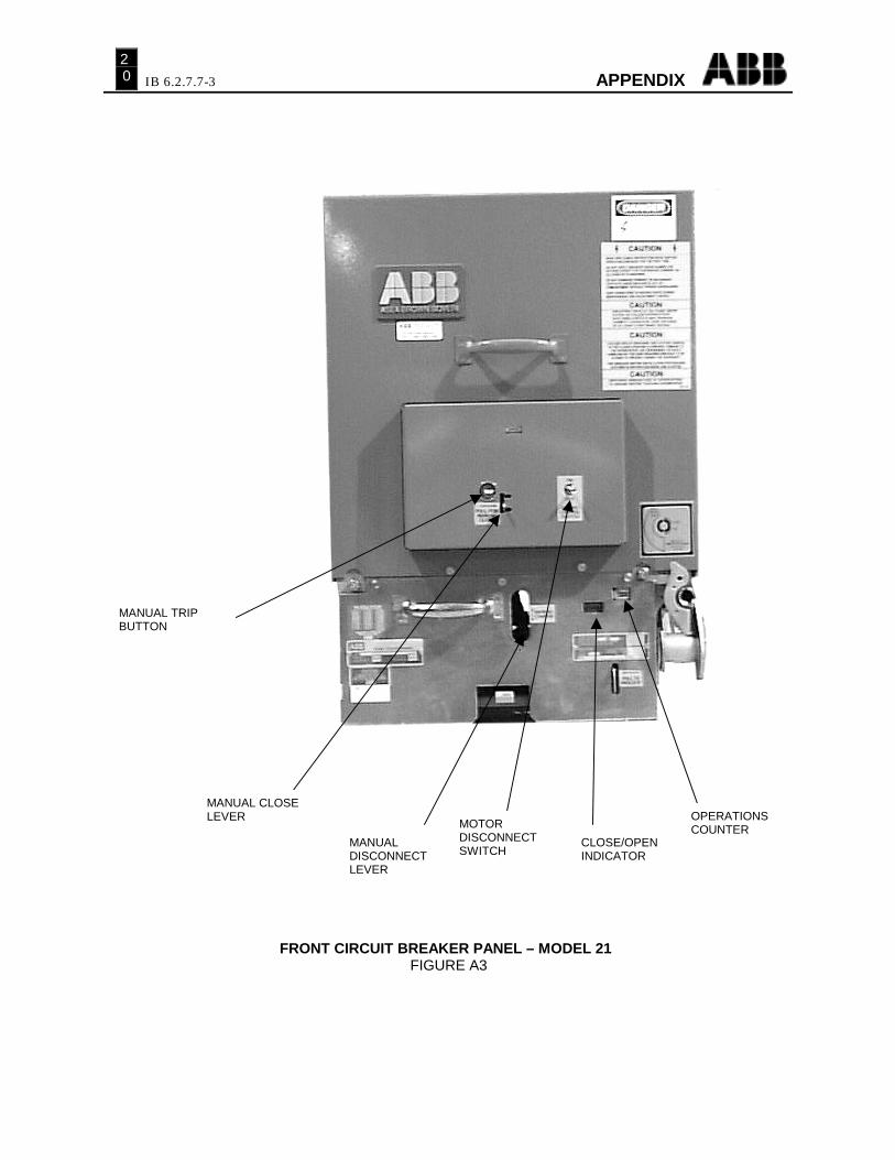
FRONT CIRCUIT BREAKER PANEL – MODEL 21FIGURE A3
MANUAL TRIPBUTTON
MANUAL CLOSELEVER
MANUALDISCONNECTLEVER
MOTORDISCONNECTSWITCH
OPERATIONSCOUNTER
CLOSE/OPENINDICATOR
APPENDIX IB 6.2.7.7-3I
21
LOCALELECTRICALCLOSEAND TRIP
FRONT CIRCUIT BREAKER PANEL & ACCESSORIES – MODEL 80FIGURE A4
OPERATIONSCOUNTER
CLOSE/OPENINDICATOR
SLOT FOR MANUALCHARGE LEVER
MANUAL CLOSELEVER
MANUAL TRIPBUTTON
MOTORDISCONNECTSWITCH
IB 6.2.7.7-3
AP
PE
ND
IX22
MA
NU
AL
CH
AR
GIN
G O
F E
LE
CT
RIC
AL
LY
OP
ER
AT
ED
CIR
CU
IT B
RE
AK
ER
SF
IGU
RE
A5
GENTLY ALLOW THE HANDLE TORETURN TO THE READY POSITIONBEING CAREFUL NOT TO ALLOWTHE HANDLE TO DISENGAGE FROMTHE PAWL CARRIER.
TOP POSITION
USE SMOOTH CONSISTENTUPWARD MOTION.
BOTTOM POSITION
AVOID SIDE-WAYS MOTION OF THEPAWL CARRIER WHEN CHARGING.
HANDLE ENGAGEMENT
1. REORIENT THE MOTOR UNTIL THE MOTOR CRANK IS IN THE POSITION AS SHOWN.FOR RYOBI STYLE MOTOR THE EXPOSED COMMUTATOR MAY BE PHYSICALLY ROTATEDIN ODER TO MOVE THE CRANK AS SHOWN.
2. INSERT THE MANUAL CHARGING HANDLE AS SHOWN.3. VERIFY THAT THE BUMPS ON THE HANDLE ARE ENGAGED INTO THE CHARGING PAWL CARRIER.4. HOLDING THE HANDLE PERPENDICULAR TO THE PAWL CARRIER, LIFT UP CAREFULLY. DO NOT ALLOW
LATERAL MOTION OF THE HANDLE.5. LISTEN FOR THE CLICK AND REPEAT 1 THRU 5 UNTIL THE BREAKER IS FULLY CHARGED.
THIS IS INDICATED BY FREEWHEELING OF THE RACTCHET ASSEMBLY.
“WINGS” ONHANDLEREMOVED FORCLARITY
ORIENTMOTORCRANK ASSHOWN
APPENDIX IB 6.2.7.7-3I
23
RACKING MECHANISMFIGURE A6
SPRING DISCHARGEADJUSTING SCREW
LINK TO TRIPLEVER
BLOCKINGLOCKBRACKET
ADJUSTABLELINK
BLOCKING LEVERLOCATED BEHINGPLATE
RELEASELEVER
RACKSCREW
PADLOCKHASP
IB 6.2.7.7-3 APPENDIX24
RACKING MECHANISM (FINAL ADJUSTMENT)FIGURE A7
0.010”0.031”
ADJUSTINGSCREW
RACKINGSHAFT
DISCHARGELINKASSEMBLY
APPENDIX IB 6.2.7.7-3I
25
METHOD OF RACKING CIRCUIT BREAKERFIGURE A8
1 – BREAKER CELL DOOR2 – ACCESS DOOR TO RACKING MECHANISM3 – RACK RELEASE LEVER4 – RACKING CRANK
IB 6.2.7.7-3 APPENDIX26
CONTACT PRESSURE (MODEL 21 AND 80)
FIGURE A9
THIN FLAT STRAIGHTEDGE TO MARKPUSHROD.STRAIGHT EDGE SHOULDBE WIDE ENOUGH TOREST ON FLAT SURFACEOF MOLDED CHAIRASSEMBLY.
PUSHROD
PUSHRODPIN
MOLDED CHAIRASSEMBLY
APPROX.6 INCHES
APPROX.3.25 INCHESWIDE
APPROX.065”THICK
CONTACT WIPE
CONTACT(WIPE) SPRING
TRUNIONBLOCK
NUT
APPENDIX IB 6.2.7.7-3I
27
TRIP LATCH ENGAGEMENT ADJUSTMENTFIGURE A10
IB 6.2.7.7-3 APPENDIX28
CONTROL DEVICE ADJUSTMENTFIGURE A11
1. ROLLER, CLOSE LATCH2. CHARGING CAM3. ACTUATOR, LIMIT SWITCH4. CONTROL DEVICE5. CLOSE LATCH RELEASE ROD6. SPRING, CLOSE LATCH RELEASE ROD7. SECONDARY CLOSE LATCH8. PRIMARY CLOSE LATCH
1
2
3
4
5
6
8
7
APPENDIX IB 6.2.7.7-3I
29
a- Auxiliary Switch Contact Closed When Breaker is Closed.b- Auxiliary Switch Contact Open When Breaker is Closed.LCb - Latch Check Switch Contact Closed When Breaker Operating Mechanism is Reset.LSa - Limit Switch Contact Open When Springs are Discharged. Closed When Springs arecharged.LSb - Limit Switch Contact Closed When Springs Are Discharged. Open When Springs areCharged.TC - Shunt Trip Coil.X - Closing Latch Release Coil.Y - Contol Relay Lockout Coil.Ya - Normally Open Relay Contact.Yb - Normally Closed Control Relay Contact.TB - Terminal Block Point.ML - Motor Lead.CE - Coil Lead End.C1,C2 - Terminal Jumper (Control Device).--< - Female Secondary Disconnect Contact.
TYPICAL DC SCHEMATIC OF CONTROL CIRCUITFIGURE A12
IB 6.2.7.7-3 APPENDIX30
TYPICAL AC SCHEMATIC DIAGRAM OF CONTROL CIRCUITFIGURE A13
c- Auxiliary Switch Contact Closed When Breaker is Closed.d- Auxiliary Switch Contact Open When Breaker is Closed.LCb - Latch Check Switch Contact Closed When Breaker Operating Mechanism isReset.LSa - Limit Switch Contact Open When Springs are Discharged. Closed WhenSprings are charged.LSb - Limit Switch Contact Closed When Springs Are Discharged. Open WhenSprings are Charged.TC - Shunt Trip Coil.X - Closing Latch Release Coil.Y - Contol Relay Lockout Coil.Ya - Normally Open Relay Contact.Yb - Normally Closed Control Relay Contact.TB - Terminal Block Point.ML - Motor Lead.CE - Coil Lead End.C1,C2 - Terminal Jumper (Control Device).--< - Female Secondary Disconnect Contact.
APPENDIX IB 6.2.7.7-3I
31
Table A1 - Control Circuit Operating Voltage Range
♠ IF CLOSING TIME IS OUT OF RANGE, CLOSING SPEED IS TO BE USED TODETERMINE IF BREAKER PERFORMANCE IS ACCEPTABLE
♣ WIPE RANGES ARE FOR NEW BREAKERS ONLY. WIPE IS ALLOWED TO DECREASE TO 0.031”.
♥ READING WITH 200 AMPS DC FLOWING. CIRCUIT BREAKERRESISTANCE IS ALLOWED TO INCREASE BY 100% FOR USED BREAKERS.
APPENDIX IB 6.2.7.7-3I
33
34
ABB Power T&D Company, Inc.Distribution Systems Division
Division HeadquartersSwitchgear Systems Circuit Breaker OperationsIEC Products & Systems OEM ComponentsAfter-market Components KIRKTM Interlock Systems


![Preparatory review study - Annex Hecodesign-fridges.eu/sites/ecodesign-fridges.eu... · Preparatory /review study - Annex H prepared by Van Holsteijn en Kemna [VHK] 16.3.2015 Commission](https://static.documents.pub/doc/80x56/5e9df0eeefc6076f4a5e338f/preparatory-review-study-annex-hecodesign-preparatory-review-study-annex-h.jpg)


