24
VB0230 HRV Solo 2.4 & ERV Quattro 2.4 22068 rev. 01 READ AND SAVE THESE INSTRUCTIONS INSTALLER: LEAVE THIS MANUAL TO THE HOMEOWNER INSTALLER AND USER MANUAL VENTILATION SYSTEM

VB0230
HRV Solo 2.4
&
ERV Quattro 2.4
22068 rev. 01
READ AND SAVE THESE INSTRUCTIONS
INSTALLER: LEAVE THIS MANUAL TO THE HOMEOWNER
INSTALLER AND USER MANUAL
VENTILATION SYSTEM
2
This manual uses the following symbols to emphasize particular information:
NOTE: Indicates supplementary information needed to fully complete an instruction.
WARNING
Identifies an instruction which, if not followed, might cause serious personal injuries including possibility of
death.
!
CAUTION
Denotes an instruction which, if not followed, may severely damage the unit and/or its components.
WARNING
Installation work and electrical wiring must be done by a qualified person(s) in accordance with all applicable
codes and standards, including fire-rated construction codes and standards.
!
ABOUT THIS MANUAL
CAUTION
Some activities create dust or vapors which may damage your unit. You must therefore turn off and unplug your
unit in the following situations:
• major renovation work
• housing construction
• sanding (e.g. gypsum joints, etc.)
• varnishing
During very heavy snowstorms, the unit should also be turned off to avoid problems caused by snow entering the
unit, even if the installation is equipped with an anti-gust intake hood.
ABOUT THIS UNIT
3
1. SERVICE ........................................................................................................................................................4-5 1.1 3-D DRAWING & PARTS ORDERING CHART .....................................................................................................................4 1.2 TECHNICAL SUPPORT ...................................................................................................................................................5
2. TECHNICAL DATA .............................................................................................................................................5-6 2.1 AIR DISTRIBUTION (NORMAL OPERATION) ........................................................................................................................5 2.2 AIR DISTRIBUTION (DEFROST MODE) ..............................................................................................................................5 2.3 DEFROST CYCLE TABLE..................................................................................................................................................5 2.4 DIMENSIONS ...............................................................................................................................................................6 2.5 CONTROLS AND FURNACE LINK OPTION ...........................................................................................................................6 2.6 SPECIFICATIONS ...........................................................................................................................................................6
3. TYPICAL INSTALLATIONS ....................................................................................................................................... 7 3.1 FULLY DUCTED SYSTEM ................................................................................................................................................7 3.2 EXHAUST DUCTED SYSTEM (SOURCE POINT VENTILATION) .................................................................................................7 3.3 SIMPLIFIED (VOLUME VENTILATION) .................................................................................................................................7
4. INSTALLATION ................................................................................................................................................ 8-13 4.1 LOCATING AND MOUNTING THE UNIT ...............................................................................................................................8 4.2 PLANNING OF THE DUCTWORK .......................................................................................................................................8 4.3 CALCULATING THE DUCT SIZE ........................................................................................................................................9 4.3.1 EXAMPLE OF CALCULATION .................................................................................................................................................... 9 4.3.2 EXAMPLE OF A DESIGN FOR A FULLY DUCTED SYSTEM .............................................................................................................. 9 4.4 INSTALLING THE DUCTWORK AND REGISTERS ..................................................................................................................10 4.4.1 FULLY DUCTED SYSTEM.......................................................................................................................................................10 4.4.2 EXHAUST DUCTED SYSTEM (SOURCE POINT VENTILATION) ........................................................................................................10 4.4.3 SIMPLIFIED INSTALLATION (VOLUME VENTILATION) .....................................................................................................................11 4.5 CONNECTING DUCT TO THE UNIT .................................................................................................................................12 4.6 INSTALLING EXTERIOR HOODS ......................................................................................................................................13 4.7 CONNECTING THE DRAIN (HRV SOLO 2.4 UNIT ONLY) ....................................................................................................13
5. CONTROL DEVICES ........................................................................................................................................... 14 5.1 MAIN CONTROLS ...................................................................................................................................................... .14 5.2 OPTIONAL CONTROLS .................................................................................................................................................14 5.3 OTHER FEATURES ......................................................................................................................................................14
6. INSTALLATION OF THE CONTROLS .................................................................................................................... 15-17 6.1 DIMENSIONS AND SPECIFICATIONS (MAIN CONTROLS) ..................................................................................................... .15 6.2 INSTALLATION OF THE MAIN CONTROL .......................................................................................................................15-16 6.2.1 ALTITUDE MAIN CONTROL INSTALLATION .................................................................................................................................15 6.2.2 DECO-TOUCH MAIN CONTROL INSTALLATION ...........................................................................................................................16 6.2.3 MAIN CONTROL ELECTRICAL CONNECTION ..............................................................................................................................16 6.3 ELECTRICAL CONNECTION TO OPTIONAL CONTROLS ....................................................................................................... .17 6.4 ELECTRICAL CONNECTION TO THE FURNACE ...................................................................................................................17
7. WIRING DIAGRAM ............................................................................................................................................. 188. AIR FLOW BALANCING ................................................................................................................................. 19-20 8.1 WHAT YOU NEED TO BALANCE THE UNIT ...................................................................................................................... .19 8.2 PRELIMINARY STAGES TO BALANCE THE UNIT .................................................................................................................19 8.3 INSTALLATION OF FLOW COLLARS OR "FLOW MEASURING STATIONS" ...................................................................................19 8.4 BALANCING PROCEDURE .............................................................................................................................................20
9. MAINTENANCE/INSTRUCTIONS FOR USER ......................................................................................................... 21-22 9.1 REGULAR MAINTENANCE (EVERY 3 MONTHS) ..................................................................................................................21 9.2 ANNUAL MAINTENANCE (FALL) ......................................................................................................................................22
10. TROUBLESHOOTING ......................................................................................................................................23-24
TABLE OF CONTENTS
4
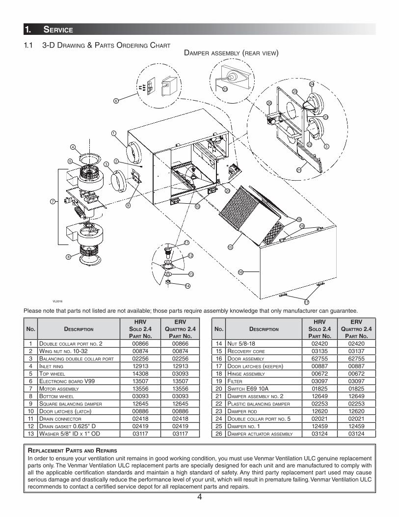
REPLACEMENT PARTS AND REPAIRS
In order to ensure your ventilation unit remains in good working condition, you must use Venmar Ventilation ULC genuine replacement parts only. The Venmar Ventilation ULC replacement parts are specially designed for each unit and are manufactured to comply with all the applicable certification standards and maintain a high standard of safety. Any third party replacement part used may cause serious damage and drastically reduce the performance level of your unit, which will result in premature failing. Venmar Ventilation ULC recommends to contact a certified service depot for all replacement parts and repairs.
NO. DESCRIPTION
HRV
SOLO 2.4
PART NO.
ERV
QUATTRO 2.4
PART NO.
1 DOUBLE COLLAR PORT NO. 2 00866 008662 WING NUT NO. 10-32 00874 008743 BALANCING DOUBLE COLLAR PORT 02256 022564 INLET RING 12913 129135 TOP WHEEL 14308 030936 ELECTRONIC BOARD V99 13507 135077 MOTOR ASSEMBLY 13556 135568 BOTTOM WHEEL 03093 030939 SQUARE BALANCING DAMPER 12645 1264510 DOOR LATCHES (LATCH) 00886 0088611 DRAIN CONNECTOR 02418 0241812 DRAIN GASKET 0.625" D 02419 0241913 WASHER 5/8" ID X 1" OD 03117 03117
Please note that parts not listed are not available; those parts require assembly knowledge that only manufacturer can guarantee.
1. SERVICE
6
1
23
4
5
7
8
9 10
11
12
13
14
15
16
17
18
19
20
21
22 3
23
2324
25
26
VL0016
1.1 3-D DRAWING & PARTS ORDERING CHARTDAMPER ASSEMBLY (REAR VIEW)
NO. DESCRIPTION
HRV
SOLO 2.4
PART NO.
ERV
QUATTRO 2.4
PART NO.
14 NUT 5/8-18 02420 0242015 RECOVERY CORE 03135 0313716 DOOR ASSEMBLY 62755 6275517 DOOR LATCHES (KEEPER) 00887 0088718 HINGE ASSEMBLY 00672 0067219 FILTER 03097 0309720 SWITCH E69 10A 01825 0182521 DAMPER ASSEMBLY NO. 2 12649 1264922 PLASTIC BALANCING DAMPER 02253 0225323 DAMPER ROD 12620 1262024 DOUBLE COLLAR PORT NO. 5 02021 0202125 DAMPER NO. 1 12459 1245926 DAMPER ACTUATOR ASSEMBLY 03124 03124
5
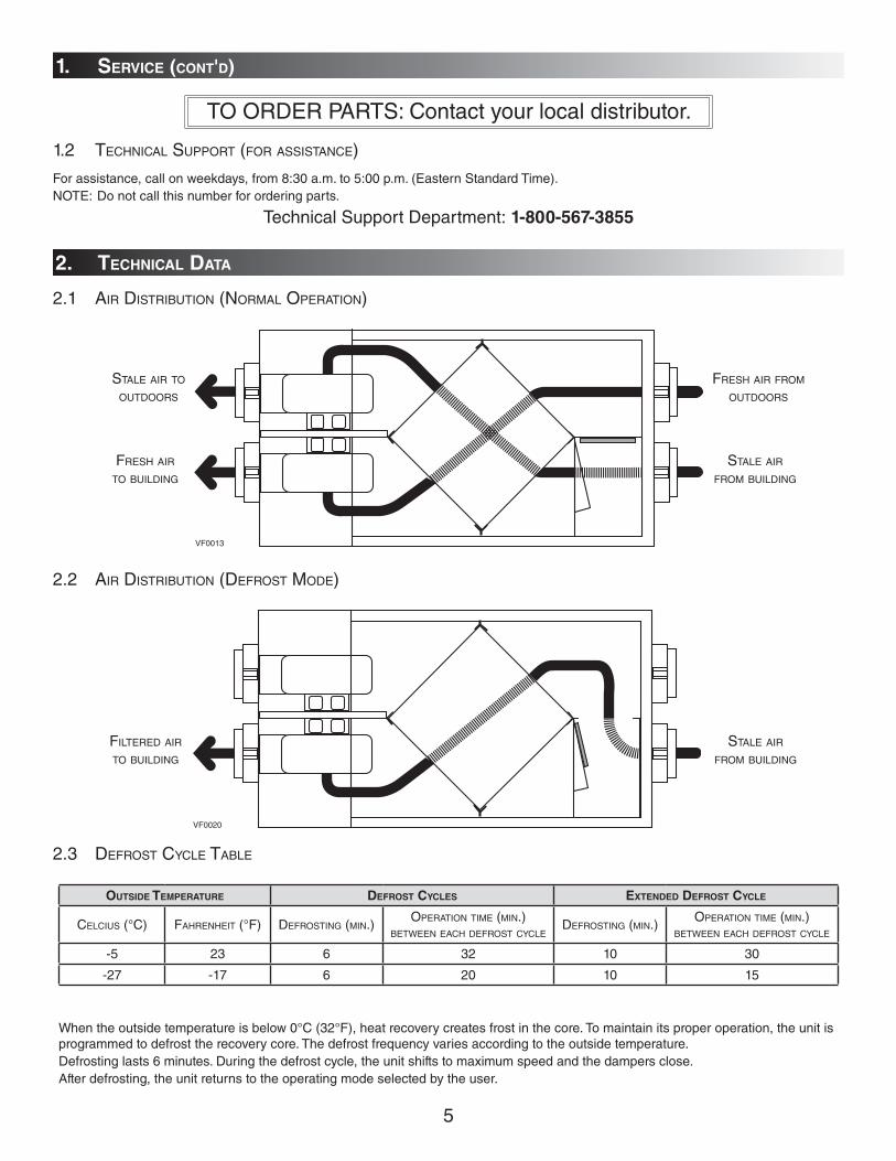
2.1 AIR DISTRIBUTION (NORMAL OPERATION)
STALE AIR TO OUTDOORS
FRESH AIR FROM OUTDOORS
FRESH AIR TO BUILDING
STALE AIR FROM BUILDING
OUTSIDE TEMPERATURE DEFROST CYCLES EXTENDED DEFROST CYCLE
CELCIUS (°C) FAHRENHEIT (°F) DEFROSTING (MIN.)OPERATION TIME (MIN.)
BETWEEN EACH DEFROST CYCLEDEFROSTING (MIN.)
OPERATION TIME (MIN.)BETWEEN EACH DEFROST CYCLE
-5 23 6 32 10 30
-27 -17 6 20 10 15
When the outside temperature is below 0°C (32°F), heat recovery creates frost in the core. To maintain its proper operation, the unit is programmed to defrost the recovery core. The defrost frequency varies according to the outside temperature.Defrosting lasts 6 minutes. During the defrost cycle, the unit shifts to maximum speed and the dampers close.After defrosting, the unit returns to the operating mode selected by the user.
2. TECHNICAL DATA
VF0013
VF0020
2.2 AIR DISTRIBUTION (DEFROST MODE)
2.3 DEFROST CYCLE TABLE
FILTERED AIR TO BUILDING
STALE AIR FROM BUILDING
1. SERVICE (CONT'D)
TO ORDER PARTS: Contact your local distributor.
1.2 TECHNICAL SUPPORT (FOR ASSISTANCE)
For assistance, call on weekdays, from 8:30 a.m. to 5:00 p.m. (Eastern Standard Time).NOTE: Do not call this number for ordering parts.
Technical Support Department: 1-800-567-3855
6
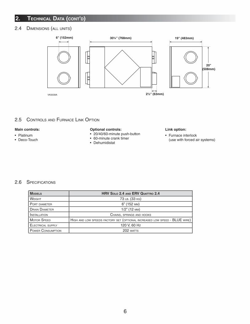
2.4 DIMENSIONS (ALL UNITS)
2. TECHNICAL DATA (CONT'D)
19" (483mm)
20"(508mm)
6" (152mm) 30¼" (768mm)
2½" (63mm)VK0039A
2.5 CONTROLS AND FURNACE LINK OPTION
Main controls:
• Platinum• Deco-Touch
Optional controls:
• 20/40/60-minute push-button• 60-minute crank timer• Dehumidistat
Link option:
• Furnace interlock (use with forced air systems)
2.6 SPECIFICATIONS
MODELS HRV SOLO 2.4 AND ERV QUATTRO 2.4
WEIGHT 73 LB. (33 KG)PORT DIAMETER 6” (152 MM)DRAIN DIAMETER 1/2” (12 MM)INSTALLATION CHAINS, SPRINGS AND HOOKS
MOTOR SPEED HIGH AND LOW SPEEDS FACTORY SET (OPTIONAL INCREASED LOW SPEED - BLUE WIRE)ELECTRICAL SUPPLY 120 V, 60 HZ
POWER CONSUMPTION 202 WATTS
7
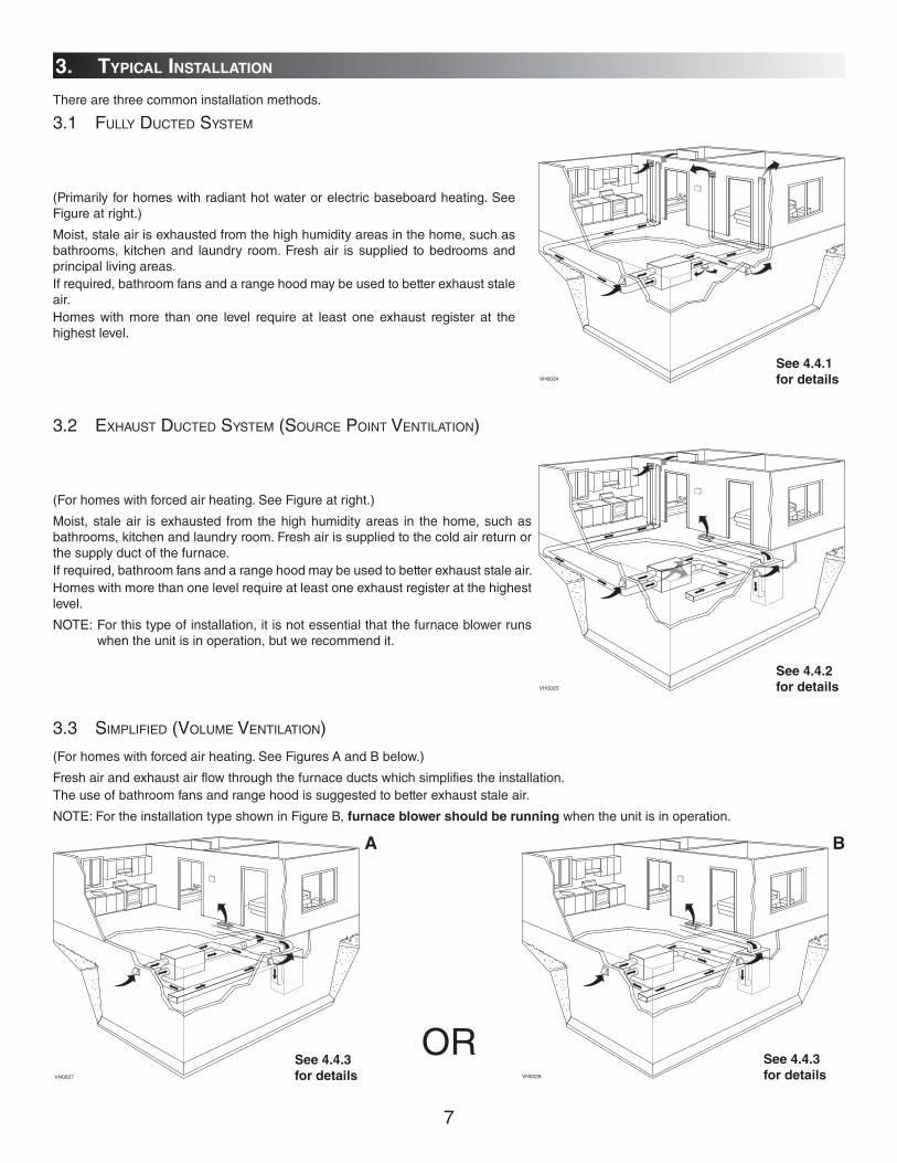
3.1 FULLY DUCTED SYSTEM
(Primarily for homes with radiant hot water or electric baseboard heating. See Figure at right.)
Moist, stale air is exhausted from the high humidity areas in the home, such as bathrooms, kitchen and laundry room. Fresh air is supplied to bedrooms and principal living areas.If required, bathroom fans and a range hood may be used to better exhaust stale air. Homes with more than one level require at least one exhaust register at the highest level.
VH0024
See 4.4.1
for details
3.2 EXHAUST DUCTED SYSTEM (SOURCE POINT VENTILATION)
(For homes with forced air heating. See Figure at right.)
Moist, stale air is exhausted from the high humidity areas in the home, such as bathrooms, kitchen and laundry room. Fresh air is supplied to the cold air return or the supply duct of the furnace.If required, bathroom fans and a range hood may be used to better exhaust stale air. Homes with more than one level require at least one exhaust register at the highest level.
NOTE: For this type of installation, it is not essential that the furnace blower runs when the unit is in operation, but we recommend it.
VH0025
See 4.4.2
for details
3.3 SIMPLIFIED (VOLUME VENTILATION)
(For homes with forced air heating. See Figures A and B below.)
Fresh air and exhaust air flow through the furnace ducts which simplifies the installation.The use of bathroom fans and range hood is suggested to better exhaust stale air.
NOTE: For the installation type shown in Figure B, furnace blower should be running when the unit is in operation.
VH0027 VH0026
See 4.4.3
for details
See 4.4.3
for details
OR
A B
3. TYPICAL INSTALLATION
There are three common installation methods.

8
WARNING
When applicable local regulations comprise more restrictive installation and/or certification requirements, the
aforementioned requirements prevail on those of this document and the installer agrees to conform to these at
his own expenses.
!
INSPECTING THE BOX CONTENT
• Inspect the exterior of the unit for shipping damage. Ensure that there is no damage to the door, door latches, door hinges, dampers, duct collars, cabinet, etc.
• Inspect the interior of the unit for damage. Ensure that the fan motor assembly, recovery core, insulation, dampers, damper actuator and drain pan are all intact.
• If the unit was damaged during shipping, contact your local distributor. (Claims must be made within 24 hours after delivery.)• Use checklist included with the unit to ensure that no parts are missing.
4.1 LOCATING AND MOUNTING THE UNIT
Choose an appropriate location for the unit:
• Within an area of the house where the temperature is kept above 150°F and below 104°F
• Away from living areas (dining room, living room, bedroom), if possible.• So as to provide easy access to the interior cabinet for every three months and annual
maintenance, and to the control panel on the right hand side of the unit.• Close to an exterior wall, so as to limit the length of the insulated flexible duct to and from
the unit.• Close to a drain. If no drain is close by, use a pail to collect run-off.• Away from hot chimneys, electrical panel and other fire hazards.• Allow for a power source (110 V standard outlet).
CAUTION
Make sure the unit is level.
4.2 PLANNING THE DUCTWORK
a) Follow the instructions in Section4.3 on next page to determine the appropriate duct diameters for your system.
b) Keep it simple. Plan for a minimum number of bends and joints. Keep the length of insulated duct to a minimum.
c) Do not use wall cavities as ducts. Do not use branch lines smaller than 4” (102 mm) Ø.
d) Do not ventilate crawl spaces or cold rooms. Do not attempt to recover the exhaust air from a dryer or a range hood. This would cause clogging of the recovery module. Use sheet metal for the kitchen exhaust duct.
e) Be sure to plan for at least one exhaust register on the highest lived-in level of the house if it has 2 floors or more.
4. INSTALLATION
WARNING
When performing installation, servicing or cleaning the unit, it is recommended to wear safety glasses and gloves.
!
VD0064
Hang the unit to ceiling joists with the 4 chains, springs and hooks (included) (see figure at right).

9
4.3 CALCULATING DUCT SIZE
Use the table below to ensure that the ducts you intend to install will be carrying air flows at or under the recommended values.
Avoid installing ducts that will have to carry air flows near the maximum values and never install a duct if its air flow exceeds
the maximum value.
NOTE: Examples 4.3.1 and 4.3.2 use imperial measures. The same calculation applies to metric measures.
4.3.1 EXAMPLE OF CALCULATION: Problem: My installation requires two exhaust registers (one for the kitchen, one for the bathroom). I will connect these
registers to a main duct which will connect to the unit (high speed performance value of 140 cfm). What size of duct should I use for the main exhaust duct and for the two end branches leading to the registers? (See Figure above.)
Solution: Simplified method. (For a more detailed method of calculating duct size refer to the ASHRAE or HRAI HANDBOOK.)
Main duct: Table above indicates a 6” Ø duct: Recommended air flow: 120 cfm; maximum air flow: 180 cfm. The high speed air flow of 140 cfm is close enough to the recommended value (120) and far enough away from the maximum value (180). Therefore a 6” Ø duct or larger is an appropriate choice for the main exhaust duct.
End branches: Each end branch will have to transport an air flow of 70 cfm (140 divided by 2). Table above indicates a 5” Ø duct: Recommended air flow: 75 cfm; maximum air flow: 110 cfm. The high speed air flow of 70 cfm is close enough to the recommended value (75) and far enough away from the maximum value (110). Therefore a 5” Ø duct or larger is an appropriate choice for both end branches.
NOTE: A 4" Ø duct would have been too small because the maximum acceptable value for a 4"Ø duct is 60 cfm.
4.3.2 EXAMPLE OF A DESIGN FOR A FULLY DUCTED SYSTEM FOR A UNIT HAVING A HIGH SPEED PERFORMANCE OF 222 CFM
VI0003
END BRANCHES
5" Ø,70 CFM
MAIN BRANCH6" Ø, 140 CFM
140 CFM
VI0004
5"5" 4"
4"
4"
4"
6" 6"
6"
6"
7"7"
6" Ø, 93 CFM
6" Ø, 129 CFM
5" Ø, 65 CFM
5" Ø, 64 CFM
4" Ø, 42 CFM
4" Ø, 42 CFM
6" Ø, 84 CFM
7" Ø, 222 CFM
6" Ø, 138 CFM
6" Ø, 96 CFM
DUCT DIAMETER RECOMMENDED AIRFLOW MAXIMUM AIRFLOW
4" 40 CFM 19 L/S 68 M³/H 60 CFM 28 L/S 102 M³/H
5" 75 CFM 35 L/S 127 M³/H 110 CFM 52 L/S 187 M³/H
6" 120 CFM 57 L/S 204 M³/H 180 CFM 85 L/S 306 M³/H
7" 185 CFM 87 L/S 314 M³/H 270 CFM 127 L/S 459 M³/H
8" 260 CFM 123 L/S 442 M³/H 380 CFM 179 L/S 645 M³/H
4. INSTALLATION (CONT'D)
10
WARNING
When performing duct connection to the furnace, installation must be done in accordance with all applicable
codes and standards. Please refer to your local building code.
!
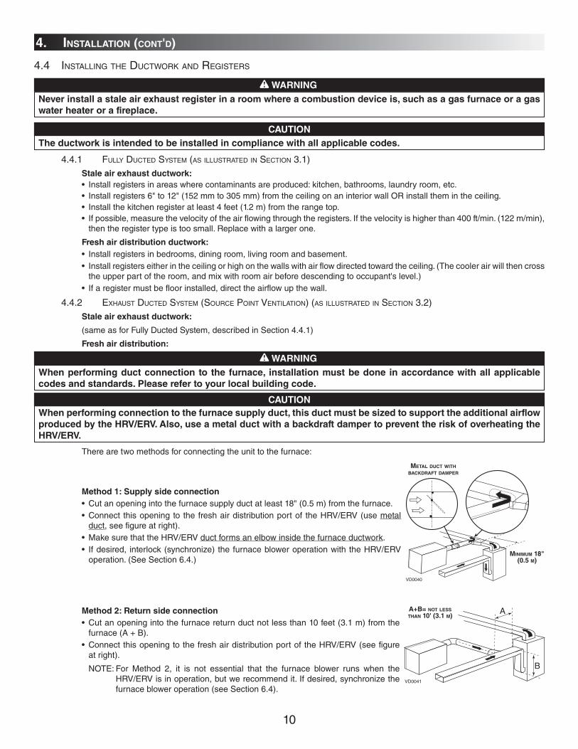
There are two methods for connecting the unit to the furnace:
Method 1: Supply side connection
• Cut an opening into the furnace supply duct at least 18" (0.5 m) from the furnace. • Connect this opening to the fresh air distribution port of the HRV/ERV (use metal
duct, see figure at right). • Make sure that the HRV/ERV duct forms an elbow inside the furnace ductwork. • If desired, interlock (synchronize) the furnace blower operation with the HRV/ERV
operation. (See Section 6.4.)
Method 2: Return side connection
• Cut an opening into the furnace return duct not less than 10 feet (3.1 m) from the furnace (A + B).
• Connect this opening to the fresh air distribution port of the HRV/ERV (see figure at right).
NOTE: For Method 2, it is not essential that the furnace blower runs when the HRV/ERV is in operation, but we recommend it. If desired, synchronize the furnace blower operation (see Section 6.4).
CAUTION
When performing connection to the furnace supply duct, this duct must be sized to support the additional airflow
produced by the HRV/ERV. Also, use a metal duct with a backdraft damper to prevent the risk of overheating the
HRV/ERV.
A+B= NOT LESS THAN 10' (3.1 M)
B
A
VD0041
4. INSTALLATION (CONT'D)
4.4 INSTALLING THE DUCTWORK AND REGISTERS
WARNING
Never install a stale air exhaust register in a room where a combustion device is, such as a gas furnace or a gas
water heater or a fireplace.
!
CAUTION
The ductwork is intended to be installed in compliance with all applicable codes.
4.4.1 FULLY DUCTED SYSTEM (AS ILLUSTRATED IN SECTION 3.1) Stale air exhaust ductwork:
• Install registers in areas where contaminants are produced: kitchen, bathrooms, laundry room, etc. • Install registers 6" to 12" (152 mm to 305 mm) from the ceiling on an interior wall OR install them in the ceiling. • Install the kitchen register at least 4 feet (1.2 m) from the range top. • If possible, measure the velocity of the air flowing through the registers. If the velocity is higher than 400 ft/min. (122 m/min),
then the register type is too small. Replace with a larger one.
Fresh air distribution ductwork:
• Install registers in bedrooms, dining room, living room and basement. • Install registers either in the ceiling or high on the walls with air flow directed toward the ceiling. (The cooler air will then cross
the upper part of the room, and mix with room air before descending to occupant's level.) • If a register must be floor installed, direct the airflow up the wall.
4.4.2 EXHAUST DUCTED SYSTEM (SOURCE POINT VENTILATION) (AS ILLUSTRATED IN SECTION 3.2) Stale air exhaust ductwork:
(same as for Fully Ducted System, described in Section 4.4.1)
Fresh air distribution:
VD0040
MINIMUM 18" (0.5 M)
METAL DUCT WITH BACKDRAFT DAMPER
11
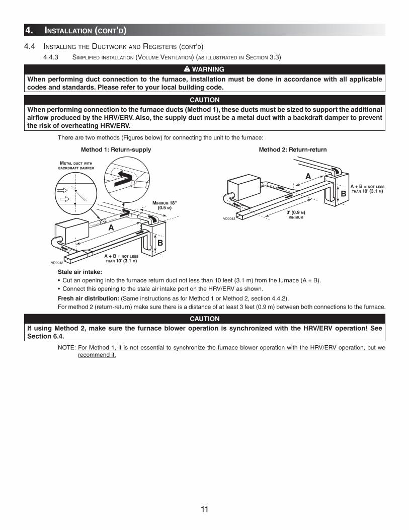
4.4 INSTALLING THE DUCTWORK AND REGISTERS (CONT'D) 4.4.3 SIMPLIFIED INSTALLATION (VOLUME VENTILATION) (AS ILLUSTRATED IN SECTION 3.3)
WARNING
When performing duct connection to the furnace, installation must be done in accordance with all applicable
codes and standards. Please refer to your local building code.
!
CAUTION
When performing connection to the furnace ducts (Method 1), these ducts must be sized to support the additional
airflow produced by the HRV/ERV. Also, the supply duct must be a metal duct with a backdraft damper to prevent
the risk of overheating HRV/ERV.
Stale air intake:
• Cut an opening into the furnace return duct not less than 10 feet (3.1 m) from the furnace (A + B). • Connect this opening to the stale air intake port on the HRV/ERV as shown.
Fresh air distribution: (Same instructions as for Method 1 or Method 2, section 4.4.2). For method 2 (return-return) make sure there is a distance of at least 3 feet (0.9 m) between both connections to the furnace.
There are two methods (Figures below) for connecting the unit to the furnace:
Method 1: Return-supply Method 2: Return-return
MINIMUM 18" (0.5 M)
METAL DUCT WITH BACKDRAFT DAMPER
VD0042
A
B
VD0043
A
BA + B = NOT LESS THAN 10’ (3.1 M)
A + B = NOT LESS THAN 10’ (3.1 M)
3' (0.9 M)MINIMUM
CAUTION
If using Method 2, make sure the furnace blower operation is synchronized with the HRV/ERV operation! See
Section 6.4.
4. INSTALLATION (CONT'D)
NOTE: For Method 1, it is not essential to synchronize the furnace blower operation with the HRV/ERV operation, but we recommend it.
12
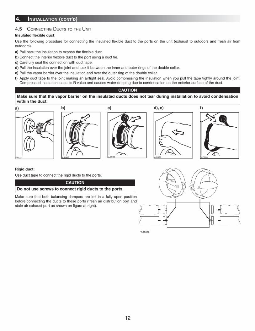
Rigid duct:
Use duct tape to connect the rigid ducts to the ports.
Make sure that both balancing dampers are left in a fully open position before connecting the ducts to these ports (fresh air distribution port and stale air exhaust port as shown on figure at right).
4.5 CONNECTING DUCTS TO THE UNIT
Insulated flexible duct:
Use the following procedure for connecting the insulated flexible duct to the ports on the unit (exhaust to outdoors and fresh air from outdoors).
a) Pull back the insulation to expose the flexible duct.b) Connect the interior flexible duct to the port using a duct tie.c) Carefully seal the connection with duct tape.d) Pull the insulation over the joint and tuck it between the inner and outer rings of the double collar.e) Pull the vapor barrier over the insulation and over the outer ring of the double collar.f) Apply duct tape to the joint making an airtight seal. Avoid compressing the insulation when you pull the tape tightly around the joint.
Compressed insulation loses its R value and causes water dripping due to condensation on the exterior surface of the duct.
CAUTION
Make sure that the vapor barrier on the insulated ducts does not tear during installation to avoid condensation
within the duct.
VJ0001 VJ0002 VJ0003 VJ0004 VJ0005
CAUTION
Do not use screws to connect rigid ducts to the ports.
4. INSTALLATION (CONT'D)
VJ0009
a) b) c) d), e) f)

13
VO0011
4.6 INSTALLING THE EXTERIOR HOODS
Choose an appropriate location to install the exterior hoods:
• There must be a minimum distance of 6' (1.8 m) between the hoods to avoid cross-contamination
• There must be a minimum distance of 18" (457 mm) from the ground
Refer to figure at right to connect the insulated duct to the hoods. Place the “FRESH AIR INTAKE” sticker, provided in the installation kit, on corresponding hood. An anti-gust intake hood should be installed in regions where a lot of snow is expected to fall.
Make sure the intake hood is at least 6' (1.8 m) away
from any of the following:
• Dryer exhaust, high efficiency furnace vent, central
vacuum vent
• Gas meter exhaust, gas barbecue-grill
• Any exhaust from a combustion source
• Garbage bin and any other source of contamination
WARNING!
4.7 CONNECTING THE DRAIN (HRV SOLO 2.4 UNIT ONLY)
Attach both plastic drain fittings to the unit using the gaskets, washers and nuts as shown.
TIE WRAP
VO0003VO0005A
± 12" (± 305 mm)
± 12" (± 305 mm)
VD0231A
± 1”
Cut 2 sections of plastic tubing, about 12" (305 mm) long and attach them to each drain fitting. Join these 2 short sections to the “T” junction and main tube as shown.
Make a water trap loop in the tube to prevent the unit from drawing unpleasant odors from the drain source. Make sure this loop is located BELOW the “T” as shown. This will prevent water from being drawn back up into the unit in case of negative pressure. Run the tube to the floor drain or to an alternative drain pipe or pail. Be sure there is a slight slope for the run-off.
TO DRAIN
If using a pail to collect water, locate the tube end approximately 1" from the top of the pail in order to prevent water from being drawn back up into the unit.
4. INSTALLATION (CONT'D)
VD0028
EXHAUST HOOD
INTAKE HOOD
TAPE AND DUCT TIE
18"
(457 MM)
6'
(1.8 M)
18"
(457 MM)
18"
(457 MM)
6'
(1.8 M)
OPTIONAL DUCT LOCATION
6"
(152 MM)
CAULKING
CAUTION
This model requires an exhaust hood with a backdraft
damper. This damper closes when the unit is off and
prevents unwanted cold air from entering the house.

14
5. CONTROL DEVICES
5.1 MAIN CONTROLS
AltitudeDeco-Touch
VC0101
SMARTSETMODEPREF
VC0119
MAIN WALL CONTROL DECO-TOUCH ALTITUDE
MODES
OFF Position X X
Intermittent exchange (TBI) 20 ON - 40 OFF
Intermittent exchange OR OFF (ON - OFF or ON - Recirculation) X X
Low speed continuous exchange X X
High speed continuous exchange X X
SMART (entirely automatic mode optimizing ventilation) X
Program (programs the desired ventilation according to the period of the day) X
Recirculation (manual mode performing air recirculation inside the house) X X
DETECTOR TYPES
Outdoor temperature X
Indoor relative humidity X
INDICATORS
Mode indicator X X
Air exchange indicator X X
Maintenance indicator X X
Day and hour indicators X
SWITCHES Push button X X
5.2 OPTIONAL CONTROLS
20/40/60-Minute Push-Button Timer:
This remote illuminated switch is typically installed in bathrooms, kitchen and laundry room to provide 20, 40 or 60 minutes of high speed ventilation at the push of a button. The switch is supplied and mounted on a white single gang wall plate.
Mechanical Timer:
This timer allows up to 60 minutes of high speed operation to be selected from a remote location.
5.3 OTHER FEATURES
Furnace Interlock (for forced air heating system)
The furnace fan can be interlocked so that it will run simultaneously with the HRV to ensure proper distribution of fresh air throughout the house.
Permanent Memory
Our electronic controls have a default memory feature in the event of a power outage. Even the date of the last service reminder is maintained as a convenience to the homeowner.
NOTE: For Altitude control only, if the power failure duration is more than 4 hours, the day and hour settings must be reprogrammed.
15
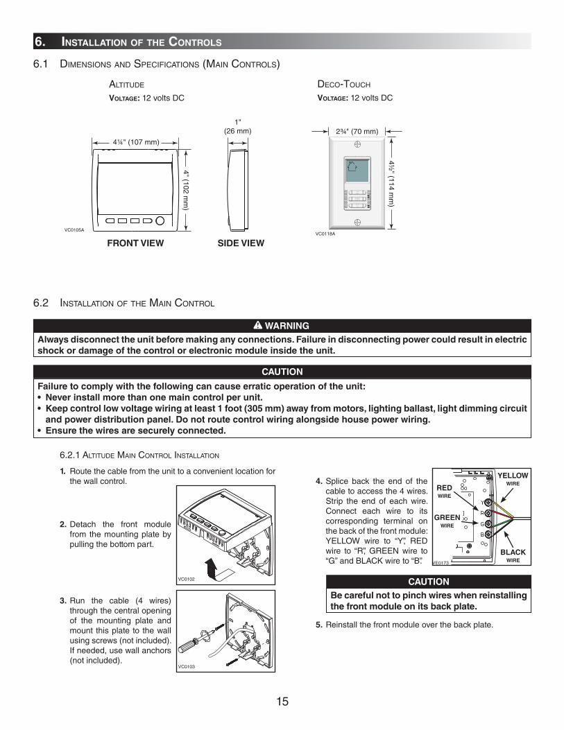
6.2.1 ALTITUDE MAIN CONTROL INSTALLATION
WARNING
Always disconnect the unit before making any connections. Failure in disconnecting power could result in electric
shock or damage of the control or electronic module inside the unit.
!
CAUTION
Failure to comply with the following can cause erratic operation of the unit:
• Never install more than one main control per unit.
• Keep control low voltage wiring at least 1 foot (305 mm) away from motors, lighting ballast, light dimming circuit
and power distribution panel. Do not route control wiring alongside house power wiring.
• Ensure the wires are securely connected.
1. Route the cable from the unit to a convenient location for the wall control.
2. Detach the front module from the mounting plate by pulling the bottom part.
3. Run the cable (4 wires) through the central opening of the mounting plate and mount this plate to the wall using screws (not included). If needed, use wall anchors (not included).
VC0102
VC0103
4. Splice back the end of the cable to access the 4 wires. Strip the end of each wire. Connect each wire to its corresponding terminal on the back of the front module: YELLOW wire to “Y”, RED wire to “R”, GREEN wire to “G” and BLACK wire to “B”.
5. Reinstall the front module over the back plate.
VE0173
REDWIRE
GREENWIRE
YELLOWWIRE
BLACKWIRE
CAUTION
Be careful not to pinch wires when reinstalling
the front module on its back plate.
6. INSTALLATION OF THE CONTROLS
6.1 DIMENSIONS AND SPECIFICATIONS (MAIN CONTROLS)
ALTITUDE
VOLTAGE: 12 volts DC
DECO-TOUCH
VOLTAGE: 12 volts DC
VC0105A
1"(26 mm)
4¼" (107 mm)
4" (102 mm
)
FRONT VIEW SIDE VIEW
VC0118A
2¾" (70 mm)
4½" (114 m
m)
6.2 INSTALLATION OF THE MAIN CONTROL

16
1. Cut a 27∕8" x 1³∕8" hole in wall at a convenient location for the wall control. Route the cable from the unit to this hole.
NOTE: Dimensions shown are for an installation without wall box.
2. Temporarily place the switch over the hole and mark both mounting screw hole positions.
3. Remove the switch, drill both screw holes (Ø 3/16") in wall and insert wall anchors (included).
4. Strip the end of the cable to access the 4 wires. Strip the end of each wire. Using a small flat blade screwdriver, connect each wire to its corresponding terminal on the back of the wall control: YELLOW wire to “Y”, RED wire to “R”, GREEN wire to “G” and BLACK wire to “B”.
5. Mount the wall control to the wall.
VC0116A
Ø 3/16”, typ.
Y
B
GR
VE0243
VC0115
6.2.2 DECO-TOUCH MAIN CONTROL INSTALLATION
6. INSTALLATION OF THE CONTROLS (CONT'D)
6.2 INSTALLATION OF THE MAIN CONTROL (CONT'D)
6.2.3 MAIN CONTROL ELECTRICAL CONNECTION
F F I OCOLY R G B
Y R G B
VE0330
SMARTSETMODEPREF
ALTITUDE / DECO-TOUCH
1. Connect the wires to their corresponding position inside the electrical compartment. Make sure the connections of the unit and of the control correspond exactly. (See figure at right.)
2. Connect the optional control (if applicable) by referring to Section 6.3. 3. Do the appropriate connection to the furnace (if applicable) by referring to Section 6.4. 4. NOTE: If the unit is installed in a cold region, set up “extended defrost” by removing jumper
JU1F on the main circuit board inside the electrical compartment (see Section 7). 5. Plug in the unit and test the wall control operation (For more details about control operation, refer to the wall control user guide,
included with the unit).
17
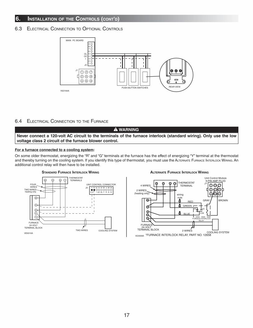
WARNING
Never connect a 120-volt AC circuit to the terminals of the furnace interlock (standard wiring). Only use the low
voltage class 2 circuit of the furnace blower control.
!
For a furnace connected to a cooling system:
On some older thermostat, energizing the “R” and “G” terminals at the furnace has the effect of energizing “Y” terminal at the thermostat and thereby turning on the cooling system. If you identify this type of thermostat, you must use the ALTERNATE FURNACE INTERLOCK WIRING. An additional control relay will then have to be installed.
STANDARD FURNACE INTERLOCK WIRING ALTERNATE FURNACE INTERLOCK WIRING
W R G Y
W
R
G
C
Y
987654321
UNIT CONTROL CONNECTOR
THERMOSTATTERMINALS
FOUR WIRES
I OC OL Y R G BF F
J3TWO WIRESheating only
FURNACE24-VOLT
TERMINAL BLOCKTWO WIRES COOLING SYSTEM
VE0010A
W R G Y
W
R
Y
R
G
Y
C
J11
2
4
5
6
8
93
*FURNACE INTERLOCKRELAY
NC NO
7
COM
7THERMOSTAT
TERMINAL
Unit Control Module
4 WIRES
2 WIRES(heating only) wiring
nuts
FURNACE24-VOLT
TERMINAL BLOCK 2 WIRESCOOLING SYSTEM
GRAY BROWNRED
GREEN
BLUE
9-PIN AMP PLUG
*FURNACE INTERLOCK RELAY, PART NO. 12658VE0009A
6. INSTALLATION OF THE CONTROLS (CONT'D)
6.4 ELECTRICAL CONNECTION TO THE FURNACE
6.3 ELECTRICAL CONNECTION TO OPTIONAL CONTROLS
987654321
OLOC
I
1 4 7
2 5 8
3 6 9
J3
MAIN PC BOARD
PUSH-BUTTON SWITCHES(HRV100H and HRV200H :5 switches maximum)
J10L 0C I
VE0164A
REAR VIEW
18
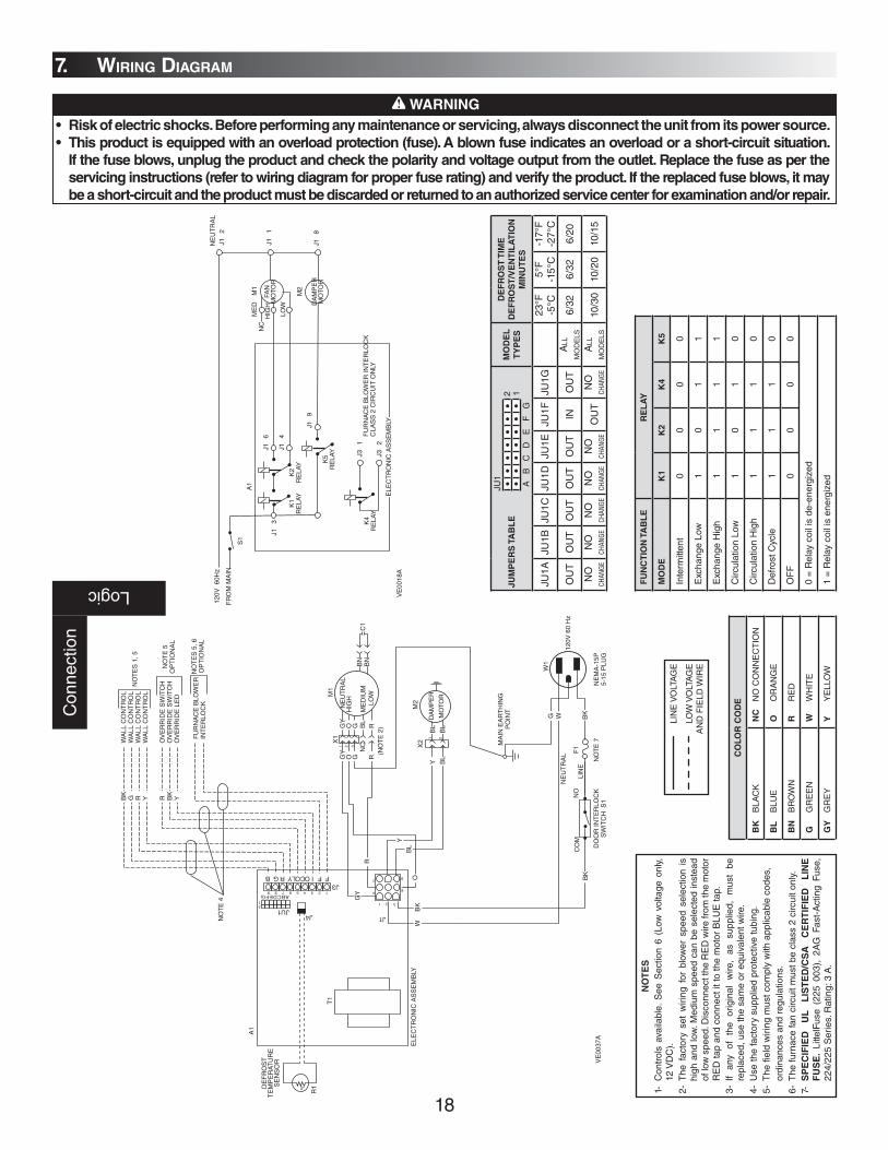
WARNING
• Risk of electric shocks. Before performing any maintenance or servicing, always disconnect the unit from its power source.
• This product is equipped with an overload protection (fuse). A blown fuse indicates an overload or a short-circuit situation.
If the fuse blows, unplug the product and check the polarity and voltage output from the outlet. Replace the fuse as per the
servicing instructions (refer to wiring diagram for proper fuse rating) and verify the product. If the replaced fuse blows, it may
be a short-circuit and the product must be discarded or returned to an authorized service center for examination and/or repair.
!B
KG R Y R B
KY
NO
TE
4
WA
LL C
ON
TR
OL
WA
LL C
ON
TR
OL
WA
LL C
ON
TR
OL
WA
LL C
ON
TR
OL
OV
ER
RID
E S
WIT
CH
OV
ER
RID
E S
WIT
CH
OV
ER
RID
E L
ED
FU
RN
AC
E B
LOW
ER
INT
ER
LOC
K
NO
TE
S 1
, 5
NO
TE
5O
PT
ION
AL
NO
TE
S 5
, 6O
PT
ION
AL
M1
X2
M2
1
21
123
1 2
4
7
6
9
3
456789
2 3
1 2
NE
UT
RA
L
ME
DIU
M
HIG
H
LOW
X1
GY
O G BL
R
GY
O GN
CR
(NO
TE
2)
BN
BN
C1
BL
BL
DA
MP
ER
MO
TOR
MA
IN E
AR
TH
ING
PO
INT
R
O
GY
W
T1
R1
A1
DE
FR
OS
TT
EM
PE
RAT
UR
ES
EN
SO
R
JU1J4 J1
J3
ABCDEFG
FFIOCOLYRGB
ELE
CT
RO
NIC
AS
SE
MB
LY
Y BL
BL
Y
CO
M12
0V 6
0 H
z
W1
G
BK
NE
MA
-15P
5-15
PLU
G
BK
DO
OR
INT
ER
LOC
KS
WIT
CH
S1
NO
NE
UT
RA
L
LIN
EB
K
VE
0037
A
-t
F1
NO
TE
7
W
7. WIRING DIAGRAMC
onne
ctio
n
Logic
A1
M1
M2
K1
RE
LAY
K2
RE
LAY K
5R
ELA
Y
FAN
MO
TOR
DA
MP
ER
MO
TOR
NE
UT
RA
L
ME
DN
CH
IGH
LOW
J1
6J1
3
J1
4
J1
9
K4
RE
LAY
J3
1
J3
2
FU
RN
AC
E B
LOW
ER
INT
ER
LOC
KC
LAS
S 2
CIR
CU
IT O
NLY
ELE
CT
RO
NIC
AS
SE
MB
LY
S1
120V
60H
z
FR
OM
MA
INJ1
2
J1
1
J1
8
VE
0018
A
NO
TE
S
1- C
ontr
ols
avai
labl
e. S
ee S
ectio
n 6
(Low
vol
tage
onl
y,
12 V
DC
).2-
The
fac
tory
set
wiri
ng f
or b
low
er s
peed
sel
ectio
n is
hi
gh a
nd lo
w. M
ediu
m s
peed
can
be
sele
cted
inst
ead
of lo
w s
peed
. Dis
conn
ect t
he R
ED
wire
from
the
mot
or
RE
D ta
p an
d co
nnec
t it t
o th
e m
otor
BLU
E ta
p.3-
If
any
of
the
orig
inal
w
ire,
as
supp
lied,
m
ust
be
repl
aced
, use
the
sam
e or
equ
ival
ent w
ire.
4- U
se th
e fa
ctor
y su
pplie
d pr
otec
tive
tubi
ng.
5- T
he fi
eld
wiri
ng m
ust c
ompl
y w
ith a
pplic
able
cod
es,
or
dina
nces
and
reg
ulat
ions
.6-
The
furn
ace
fan
circ
uit m
ust b
e cl
ass
2 ci
rcui
t onl
y.7-
SP
EC
IFIE
D
UL
L
IST
ED
/CS
A
CE
RT
IFIE
D
LIN
E
FU
SE
. Li
ttelF
use
(225
003
), 2
AG
Fas
t-A
ctin
g Fu
se,
224/
225
Ser
ies.
Rat
ing:
3 A
.
LIN
E V
OLT
AG
E
LOW
VO
LTA
GE
A
ND
FIE
LD W
IRE
CO
LO
R C
OD
E
BK
B
LAC
KN
C
NO
CO
NN
EC
TIO
N
BL
B
LUE
O
OR
AN
GE
BN
B
RO
WN
R
RE
D
G
GR
EE
NW
W
HIT
E
GY
G
RE
YY
Y
ELL
OW
JU
MP
ER
S T
AB
LE
MO
DE
L
TY
PE
S
DE
FR
OS
T T
IME
DE
FR
OS
T/V
EN
TIL
AT
ION
MIN
UT
ES
JU1A
JU1B
JU1C
JU1D
JU1E
JU1F
JU1G
23°F
-5°C
5°F
-15°
C-1
7°F
-27°
C
OU
TO
UT
OU
TO
UT
OU
TIN
OU
TA
LL
MO
DE
LS6/
326/
326/
20
NO
CH
ANGE
NO
CH
ANGE
NO
CH
ANGE
NO
CH
ANGE
NO
CH
ANGE
OU
TN
O
CHAN
GE
ALL
M
OD
ELS
10/3
010
/20
10/1
5
2 1
JU1
AB
CD
EF
G
FU
NC
TIO
N T
AB
LE
RE
LA
Y
MO
DE
K1
K2
K4
K5
Inte
rmitt
ent
00
00
Exc
hang
e Lo
w1
01
1
Exc
hang
e H
igh
11
11
Circ
ulat
ion
Low
10
10
Circ
ulat
ion
Hig
h1
11
0
Def
rost
Cyc
le1
11
0
OF
F0
00
0
0 =
Rel
ay c
oil i
s de
-ene
rgiz
ed
1 =
Rel
ay c
oil i
s en
ergi
zed

19
8.1 WHAT YOU NEED TO BALANCE THE UNIT
• A magnehelic gauge capable of measuring 0" to 0.25" water gauge (0 to 62.5 Pa) and 2 plastic tubes.
• Two ”Flow Measuring Stations” or two flow collars (the size will vary depending on the duct diameter).
8.2 PRELIMINARY STAGES TO BALANCE THE UNIT
• Seal all the unit ductwork with tape. Close all windows and doors • Turn off all exhaust devices such as range hood, dryer and bathroom fans • Make sure all filters are clean (if it is not the first time you balance the unit) • Make sure the balancing dampers are fully open (F and G in figure below)
Choose appropriate locations for both flow collars (or flow measuring stations), according to figure below:
• On the exhaust air duct (first measuring location, A) • On the fresh air distribution duct (second measuring location, B) • At least 36” away from the unit; at least 12” before or after a 90° elbow; at least 12” away from a register
8.3 INSTALLATION OF FLOW COLLARS OR “FLOW MEASURING STATIONS”
• If you are using Flow Collars:
Insert the flow collars in the duct at each location. Make sure their arrows are pointing in the direction of the airflow. Tape collars in place temporarily.
• If you are using “Flow Measuring Stations”:
Cut a 1” (25.4 mm) diameter hole in the duct at each location. Insert the “Flow Measuring Stations”. Make sure their arrows are pointing in the direction of the airflow. Tape the “Flow Measuring Stations” in place temporarily.
VP0005
12” (304mm)
12” (304mm)
36” (914mm)36” (914mm)
ORB A
GF
VP0012A
FLOW COLLAR
8. AIR FLOW BALANCING
LOWHIGH
FLOW
HIGHLOW FLOW
VP0006
FLOW MEASURING STATION
20
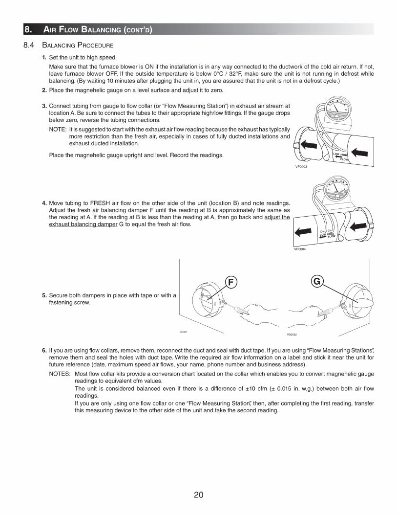
8.4 BALANCING PROCEDURE
1. Set the unit to high speed.
Make sure that the furnace blower is ON if the installation is in any way connected to the ductwork of the cold air return. If not, leave furnace blower OFF. If the outside temperature is below 0°C / 32°F, make sure the unit is not running in defrost while balancing. (By waiting 10 minutes after plugging the unit in, you are assured that the unit is not in a defrost cycle.)
2. Place the magnehelic gauge on a level surface and adjust it to zero.
3. Connect tubing from gauge to flow collar (or “Flow Measuring Station”) in exhaust air stream at location A. Be sure to connect the tubes to their appropriate high/low fittings. If the gauge drops below zero, reverse the tubing connections.
NOTE: It is suggested to start with the exhaust air flow reading because the exhaust has typically more restriction than the fresh air, especially in cases of fully ducted installations and exhaust ducted installation.
Place the magnehelic gauge upright and level. Record the readings.
4. Move tubing to FRESH air flow on the other side of the unit (location B) and note readings. Adjust the fresh air balancing damper F until the reading at B is approximately the same as the reading at A. If the reading at B is less than the reading at A, then go back and adjust the exhaust balancing damper G to equal the fresh air flow.
5. Secure both dampers in place with tape or with a fastening screw.
6. If you are using flow collars, remove them, reconnect the duct and seal with duct tape. If you are using “Flow Measuring Stations”, remove them and seal the holes with duct tape. Write the required air flow information on a label and stick it near the unit for future reference (date, maximum speed air flows, your name, phone number and business address).
NOTES: Most flow collar kits provide a conversion chart located on the collar which enables you to convert magnehelic gauge readings to equivalent cfm values.
The unit is considered balanced even if there is a difference of ±10 cfm (± 0.015 in. w.g.) between both air flow readings.
If you are only using one flow collar or one “Flow Measuring Station”, then, after completing the first reading, transfer this measuring device to the other side of the unit and take the second reading.
LOW HIGHFLOW
VP0004
8. AIR FLOW BALANCING (CONT'D)
LOW HIGH
FLOW
VP0003
VD0069
F
VD0052
G

21
9. MAINTENANCE / INSTRUCTIONS FOR USER
WARNING
Risk of electric shocks. During maintenance and repairs, the unit must always be turned off, then unplugged. We
take great care to minimize sharp edges; however, please proceed with caution when handling all components.
When cleaning the unit, it is recommended to wear safety glasses and gloves.
!
• Warn the user of the necessity to rebalance the system following a major house renovation or following the installation of any extra registers.
• Make sure the user understands how to use the main control as described in the wall control user manual.
CAUTION
Do not oil the motor. It is already permanently lubricated.
Regular maintenance should be performed every 3 months. Annual maintenance should also take place every fall season.
9.1 REGULAR MAINTENANCE (EVERY 3 MONTHS)
1. Disconnect the power supply.
2. Unlatch the door. Lift the panel towards you. Hold it firmly and hit on the right side of the panel. The door should slide to the left.
3. Clean the inside of the door with a damp cloth.
4. Clean filters. • Remove filters. • Vacuum to remove most of the dust. • Wash with a mixture of warm water and mild soap. You may add bleach if you wish to disinfect
(one tablespoon per gallon). Rinse thoroughly. Shake filters to remove excess water and let dry. NOTE: Washing the filters in the top tray of the dishwasher is possible, but the aluminum
frame might tarnish.
5. Clean the condensation tray with a damp cloth.
6. Check the exterior air intake hood:
• Make sure there are no leaves, twigs, ice or snow that could be drawn into the vent. • Clean if necessary.
7. Reassemble the components: • Filters • Door (The door is secured when you hear a click.)
8. Reconnect the power supply.
VD0005
VD0007
VD0100
VD0101
CAUTION
Even a partial blocking of this air vent could cause the unit to malfunction.

22
9. MAINTENANCE / INSTRUCTIONS FOR USER (CONT'D)
9.2 ANNUAL MAINTENANCE (FALL)
Repeat steps 1 to 6 from the Section 9.1 and continue with the following steps: 1. Clean the recovery core
• Remove the recovery core
2. Clean the centrifugal fan wheels
A Remove the wing nut.
B Disconnect the blower motor wires.
C Remove the blower assembly.
D Check for any dust accumulation on the blades.
E Clean with a small brush if necessary.
3. Put the components back in place:
• Blower assembly (blower motor wires, wing nut) • Recovery core • Filters • Door
4. Reconnect the power supply.
VD0102
VD0103
VE0050
VD0104
VD0105
CAUTION
Do not oil the motor. It is already permanently lubricated.
VD0106
Polypropylene core (HRV Solo 2.4) Enthalpic paper core (ERV Quattro 2.4)
• Let it soak in a mixture of cold or lukewarm water and mild soap (dishwashing liquid).• Rinse thoroughly.• Shake the core to remove excess water and let it dry.
• Remove dust using a vacuum cleaner with a soft brush attachment.
CAUTION
This type of recovery module cannot
be washed with water.
23
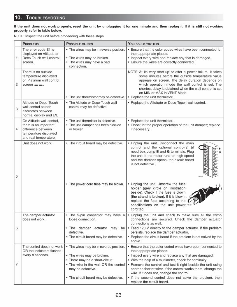
If the unit does not work properly, reset the unit by unplugging it for one minute and then replug it. If it is still not working
properly, refer to table below.
NOTE: Inspect the unit before proceeding with these steps.
• Unplug the unit. Disconnect the main control and the optional control(s) (if need be). Jump B and G terminals. Plug the unit. If the motor runs on high speed and the damper opens, the circuit board is not defective.
• Unplug the unit. Unscrew the fuse holder (grey circle on illustration beside). Check if the fuse is blown (the strand is broken). If it is blown, replace the fuse according to the specifications on the unit power cord tag.
PROBLEMS POSSIBLE CAUSES YOU SOULD TRY THIS
1
The error code E1 is displayed on Altitude or Deco-Touch wall control screen.
• The wires may be in reverse position.
• The wires may be broken.• The wires may have a bad
connection.
• Ensure that the color coded wires have been connected to their appropriate places.
• Inspect every wire and replace any that is damaged.• Ensure the wires are correctly connected.
2
There is no outside temperature displayed on Platinum wall control screen __.
• The unit thermistor may be defective.
NOTE: At its very start-up or after a power failure, it takes some minutes before the outside temperature value appears on screen. The delay duration depends on which operation mode the wall control is set. The shortest delay is obtained when the wall control is set on MIN or MAX in VENT Mode.
• Replace the unit thermistor.
3
Altitude or Deco-Touch wall control screen alternates between normal display and E3.
• The Altitude or Deco-Touch wall control may be defective.
• Replace the Altutude or Deco-Touch wall control.
4
On Altitude wall control, there is an important difference between temperature displayed and real temperature.
• The unit thermistor is defective.• The unit damper has been blocked
or broken.
• Replace the unit thermistor.• Check for the proper operation of the unit damper; replace
if necessary.
5
Unit does not work. • The circuit board may be defective.
• The power cord fuse may be blown.
6
The damper actuator does not work.
• The 9-pin connector may have a loose connection.
• The damper actuator may be defective.
• The circuit board may be defective.
• Unplug the unit and check to make sure all the crimp connections are secured. Check the damper actuator connections as well.
• Feed 120 V directly to the damper actuator. If the problem persists, replace the damper actuator.
• Replace the circuit board if the problem is not solved by the above.
7
The control does not work OR the indicators flashes every 8 seconds.
• The wires may be in reverse position.
• The wires may be broken.• There may be a short-circuit.• The wire in the wall OR the control
may be defective.
• The circuit board may be defective.
• Ensure that the color coded wires have been connected to their appropriate places.
• Inspect every wire and replace any that are damaged.• With the help of a multimeter, check for continuity. • Remove the control and test it right beside the unit using
another shorter wirer. If the control works there, change the wire. If it does not, change the control.
• If the second control does not solve the problem, then replace the circuit board.
10. TROUBLESHOOTING
VE0082
BG
VE0194
24
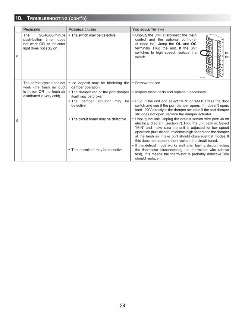
PROBLEMS POSSIBLE CAUSES YOU SOULD TRY THIS
8
The 20/40/60-minute push-button timer does not work OR its indicator light does not stay on.
• The switch may be defective.
9
The defrost cycle does not work (the fresh air duct is frozen OR the fresh air distributed is very cold).
• Ice deposit may be hindering the damper operation.
• The damper rod or the port damper itself may be broken.
• The damper actuator may be defective.
• The circuit board may be defective.
• The thermistor may be defective.
• Remove the ice.
• Inspect these parts and replace if necessary.
• Plug in the unit and select “MIN” or “MAX”. Press the door switch and see if the port damper opens. If it doesn’t open, feed 120 V directly to the damper actuator. If the port damper still does not open, replace the damper actuator.
• Unplug the unit. Unplug the defrost sensor wire (see J4 on electrical diagram, Section 7). Plug the unit back in. Select “MIN” and make sure the unit is adjusted for low speed operation (turn all dehumidistats high speed and the damper at the fresh air intake port should close (defrost mode). If this does not happen, then replace the circuit board.
• If the defrost mode works well after having disconnecting the thermistor disconnecting the thermistor wire (above test), this means the thermistor is probably defective. You should replace it.
• Unplug the unit. Disconnect the main control and the optional control(s) (if need be). Jump the OL and OC terminals. Plug the unit. If the unit switches to high speed, replace the switch
10. TROUBLESHOOTING (CONT'D)
VE0067
OLOC


