Installer and user reference guide VRV IV system air conditioner English Installer and user reference guide VRV IV system air conditioner RXYTQ8T7YF RXYTQ10T7YF RXYTQ12T7YF RXYTQ14T7YF RXYTQ16T7YF
Transcript
Installer and user reference guideVRV IV system air conditioner English
VRV IV system air conditioner4P388989-1B – 2016.02
Table of Contents
1 General safety precautions 31.1 About the documentation .......................................................... 3
1.1.1 Meaning of warnings and symbols.............................. 31.2 For the user ............................................................................... 41.3 For the installer.......................................................................... 4
1.3.1 General ....................................................................... 41.3.2 Installation site ............................................................ 41.3.3 Refrigerant .................................................................. 51.3.4 Brine............................................................................ 51.3.5 Water .......................................................................... 51.3.6 Electrical ..................................................................... 6
2 About the documentation 62.1 About this document.................................................................. 6
For the installer 7
3 About the box 73.1 Overview: About the box ........................................................... 73.2 To unpack the outdoor unit........................................................ 73.3 To remove the accessories from the outdoor unit ..................... 73.4 Accessory pipes: Diameters...................................................... 83.5 To remove the transportation stay............................................. 8
4 About the units and options 84.1 Overview: About the units and options...................................... 84.2 Identification label: Outdoor unit ................................................ 84.3 About the outdoor unit ............................................................... 84.4 System layout............................................................................ 84.5 Combining units and options ..................................................... 9
4.5.1 About combining units and options ............................. 94.5.2 Possible combinations of indoor units......................... 94.5.3 Possible options for the outdoor unit........................... 9
6 Installation 166.1 Overview: Installation ................................................................ 166.2 Opening the units ...................................................................... 17
6.2.1 To open the outdoor unit............................................. 176.2.2 To open the electrical component box of the outdoor
unit .............................................................................. 176.3 Mounting the outdoor unit.......................................................... 17
6.3.1 To provide the installation structure ............................ 176.4 Connecting the refrigerant piping .............................................. 18
6.4.1 Precautions when connecting refrigerant piping ......... 186.4.2 About connecting the refrigerant piping ...................... 186.4.3 To route the refrigerant piping..................................... 186.4.4 To connect the refrigerant piping to the outdoor unit .. 186.4.5 To connect the multi connection piping kit .................. 19
6.4.6 Multiple outdoor units: Knockout holes ........................ 196.4.7 To connect the refrigerant branching kit ...................... 196.4.8 To protect against contamination................................. 196.4.9 To braze the pipe end .................................................. 206.4.10 Using the stop valve and service port .......................... 206.4.11 To remove the pinched pipes....................................... 21
6.5 Checking the refrigerant piping .................................................. 216.5.1 About checking the refrigerant piping .......................... 216.5.2 Checking refrigerant piping: General guidelines .......... 226.5.3 Checking refrigerant piping: Setup............................... 226.5.4 To perform a leak test .................................................. 226.5.5 To perform vacuum drying ........................................... 23
6.6 To insulate the refrigerant piping................................................ 236.7 Charging refrigerant ................................................................... 23
6.7.1 Precautions when charging refrigerant ........................ 236.7.2 About charging refrigerant ........................................... 246.7.3 To determine the additional refrigerant amount ........... 246.7.4 To charge refrigerant: Flow chart................................. 246.7.5 To charge refrigerant ................................................... 266.7.6 Step 6: To manually charge refrigerant........................ 266.7.7 Error codes when charging refrigerant......................... 276.7.8 Checks after charging refrigerant................................. 27
6.8 Connecting the electrical wiring.................................................. 276.8.1 Precautions when connecting electrical wiring ............ 276.8.2 Field wiring: Overview.................................................. 286.8.3 About the electrical wiring ............................................ 286.8.4 Guidelines when knocking out knockout holes ............ 286.8.5 To route and fix the transmission wiring ...................... 286.8.6 To connect the transmission wiring.............................. 296.8.7 To finish the transmission wiring.................................. 296.8.8 To route and fix the power supply................................ 306.8.9 To connect the power supply ....................................... 30
7 Configuration 317.1 Overview: Configuration ............................................................. 317.2 Making field settings................................................................... 31
7.2.1 About making field settings .......................................... 317.2.2 Field setting components ............................................. 317.2.3 To access the field setting components....................... 317.2.4 To access mode 1 or 2 ................................................ 327.2.5 To use mode 1 ............................................................. 327.2.6 To use mode 2 ............................................................. 327.2.7 Mode 1: Monitoring settings......................................... 337.2.8 Mode 2: Field settings.................................................. 347.2.9 To connect the PC configurator to the outdoor unit ..... 36
7.3 Energy saving and optimum operation....................................... 367.3.1 Available main operation methods............................... 367.3.2 Available comfort settings ............................................ 367.3.3 Example: Automatic mode during cooling.................... 377.3.4 Example: Automatic mode during heating ................... 38
8 Commissioning 388.1 Overview: Commissioning.......................................................... 388.2 Precautions when commissioning .............................................. 388.3 Checklist before commissioning................................................. 398.4 About test run ............................................................................. 398.5 To perform a test run.................................................................. 398.6 Correcting after abnormal completion of the test run ................. 408.7 Operating the unit ....................................................................... 40
9 Maintenance and service 409.1 Overview: Maintenance and service .......................................... 409.2 Maintenance safety precautions................................................. 40
9.2.1 To prevent electrical hazards....................................... 409.3 About service mode operation.................................................... 41
9.3.1 To use vacuum mode .................................................. 419.3.2 To recover refrigerant .................................................. 41
10 Troubleshooting 4110.1 Overview: Troubleshooting......................................................... 4110.2 Solving problems based on error codes..................................... 41
1 General safety precautions
Installer and user reference guide
3RXYTQ8~16T7YFVRV IV system air conditioner4P388989-1B – 2016.02
12 Technical data 4512.1 Overview: Technical data .......................................................... 4512.2 Dimensions: Outdoor unit .......................................................... 4512.3 Service space: Outdoor unit ...................................................... 4612.4 Components: Outdoor unit ........................................................ 4712.5 Components: Electrical component box.................................... 5012.6 Piping diagram: Outdoor unit..................................................... 5112.7 Wiring diagram: Outdoor unit .................................................... 5212.8 Technical specifications: Outdoor unit....................................... 5812.9 Capacity table: Indoor unit......................................................... 60
For the user 61
13 About the system 6113.1 System layout............................................................................ 61
14 User interface 61
15 Before operation 61
16 Operation 6116.1 Operation range ........................................................................ 6116.2 Operating the system ................................................................ 62
16.2.1 About operating the system ........................................ 6216.2.2 About cooling, heating, fan only, and automatic
operation ..................................................................... 6216.2.3 About the heating operation........................................ 6216.2.4 To operate the system (WITHOUT cool/heat
changeover remote control switch) ............................. 6216.2.5 To operate the system (WITH cool/heat changeover
remote control switch)................................................. 6216.3 Using the dry program............................................................... 63
16.3.1 About the dry program ................................................ 6316.3.2 To use the dry program (WITHOUT cool/heat
changeover remote control switch) ............................. 6316.3.3 To use the dry program (WITH cool/heat changeover
remote control switch)................................................. 6316.4 Adjusting the air flow direction................................................... 63
16.4.1 About the air flow flap ................................................. 6316.5 Setting the master user interface .............................................. 64
16.5.1 About setting the master user interface ...................... 6416.5.2 To designate the master user interface (VRV DX)...... 64
16.6 About control systems ............................................................... 64
17 Energy saving and optimum operation 6417.1 Available main operation methods ............................................ 6417.2 Available comfort settings ......................................................... 65
18 Maintenance and service 6518.1 Maintenance after a long stop period ........................................ 6518.2 Maintenance before a long stop period ..................................... 6518.3 About the refrigerant.................................................................. 6518.4 After-sales service and warranty ............................................... 66
18.4.1 Warranty period .......................................................... 6618.4.2 Recommended maintenance and inspection.............. 6618.4.3 Recommended maintenance and inspection cycles... 6618.4.4 Shortened maintenance and replacement cycles ....... 66
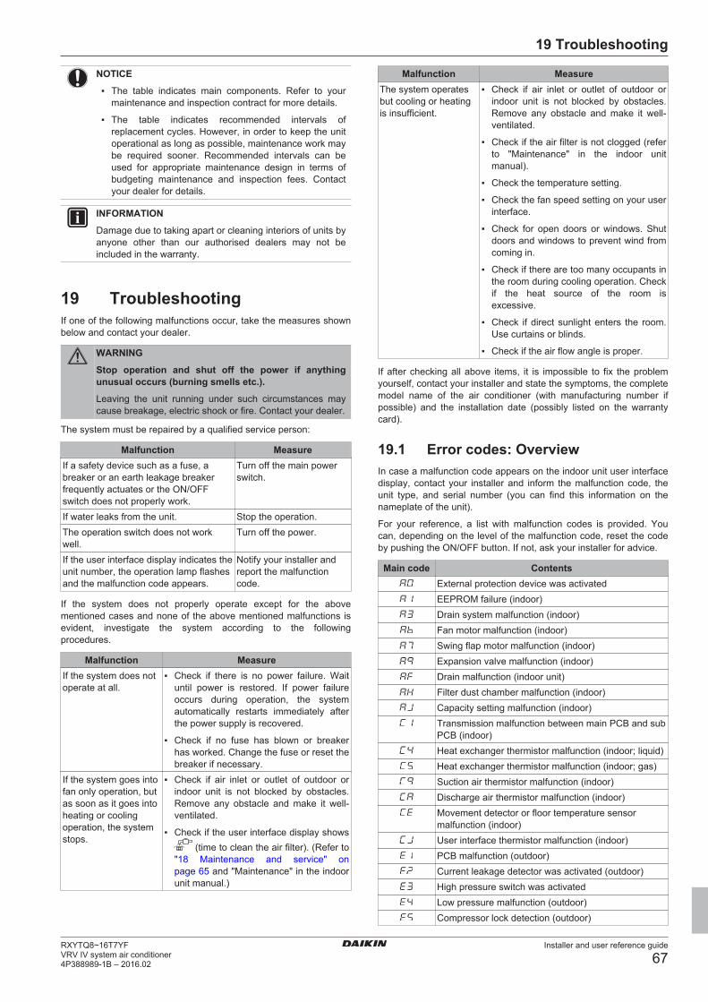
19 Troubleshooting 6719.1 Error codes: Overview............................................................... 6719.2 Symptoms that are not air conditioner troubles......................... 68
19.2.1 Symptom: The system does not operate .................... 6819.2.2 Symptom: Cool/Heat cannot be changed over ........... 6819.2.3 Symptom: Fan operation is possible, but cooling and
heating do not work..................................................... 6819.2.4 Symptom: The fan strength does not correspond to
the setting ................................................................... 68
19.2.5 Symptom: The fan direction does not correspond tothe setting .................................................................... 68
19.2.6 Symptom: White mist comes out of a unit (Indoorunit) .............................................................................. 68
19.2.7 Symptom: White mist comes out of a unit (Indoorunit, outdoor unit) ......................................................... 69
19.2.8 Symptom: The user interface display reads "U4" or"U5" and stops, but then restarts after a few minutes.. 69
19.2.9 Symptom: Noise of air conditioners (Indoor unit)......... 6919.2.10 Symptom: Noise of air conditioners (Indoor unit,
outdoor unit)................................................................. 6919.2.11 Symptom: Noise of air conditioners (Outdoor unit) ...... 6919.2.12 Symptom: Dust comes out of the unit .......................... 6919.2.13 Symptom: The units can give off odours...................... 6919.2.14 Symptom: The outdoor unit fan does not spin ............. 6919.2.15 Symptom: The display shows "88"............................... 6919.2.16 Symptom: The compressor in the outdoor unit does
not stop after a short heating operation ....................... 6919.2.17 Symptom: The inside of an outdoor unit is warm
even when the unit has stopped .................................. 6919.2.18 Symptom: Hot air can be felt when the indoor unit is
1.1 About the documentation▪ The original documentation is written in English. All other
languages are translations.
▪ The precautions described in this document cover very importanttopics, follow them carefully.
▪ The installation of the system, and all activities described in theinstallation manual and the installer reference guide must beperformed by an authorized installer.
1.1.1 Meaning of warnings and symbols
DANGER
Indicates a situation that results in death or serious injury.
DANGER: RISK OF ELECTROCUTION
Indicates a situation that could result in electrocution.
DANGER: RISK OF BURNING
Indicates a situation that could result in burning because ofextreme hot or cold temperatures.
WARNING: FLAMMABLE MATERIAL
WARNING
Indicates a situation that could result in death or seriousinjury.
CAUTION
Indicates a situation that could result in minor or moderateinjury.
NOTICE
Indicates a situation that could result in equipment orproperty damage.
1 General safety precautions
Installer and user reference guide
4RXYTQ8~16T7YF
VRV IV system air conditioner4P388989-1B – 2016.02
INFORMATION
Indicates useful tips or additional information.
1.2 For the user▪ If you are not sure how to operate the unit, contact your installer.
▪ This appliance can be used by children aged from 8 years andabove and persons with reduced physical, sensory or mentalcapabilities or lack of experience and knowledge if they have beengiven supervision or instruction concerning use of the appliance ina safe way and understand the hazards involved. Children shallnot play with the appliance. Cleaning and user maintenance shallnot be made by children without supervision.
WARNING
To prevent electric shocks or fire:
▪ Do NOT rinse the unit.
▪ Do NOT operate the unit with wet hands.
▪ Do NOT place any objects containing water on the unit.
NOTICE
▪ Do NOT place any objects or equipment on top of theunit.
▪ Do NOT sit, climb or stand on the unit.
▪ Units are marked with the following symbol:
This means that electrical and electronic products may not bemixed with unsorted household waste. Do NOT try to dismantlethe system yourself: the dismantling of the system, treatment ofthe refrigerant, of oil and of other parts must be done by anauthorized installer and must comply with applicable legislation.Units must be treated at a specialized treatment facility for reuse,recycling and recovery. By ensuring this product is disposed ofcorrectly, you will help to prevent potential negative consequencesfor the environment and human health. For more information,contact your installer or local authority.
▪ Batteries are marked with the following symbol:
This means that the batteries may not be mixed with unsortedhousehold waste. If a chemical symbol is printed beneath thesymbol, this chemical symbol means that the battery contains aheavy metal above a certain concentration.Possible chemical symbols are: Pb: lead (>0.004%).Waste batteries must be treated at a specialized treatment facilityfor reuse. By ensuring waste batteries are disposed of correctly,you will help to prevent potential negative consequences for theenvironment and human health.
1.3 For the installer
1.3.1 GeneralIf you are not sure how to install or operate the unit, contact yourdealer.
NOTICE
Improper installation or attachment of equipment oraccessories could result in electric shock, short-circuit,leaks, fire or other damage to the equipment. Only useaccessories, optional equipment and spare parts made orapproved by Daikin.
WARNING
Make sure installation, testing and applied materialscomply with applicable legislation (on top of theinstructions described in the Daikin documentation).
CAUTION
Wear adequate personal protective equipment (protectivegloves, safety glasses,…) when installing, maintaining orservicing the system.
WARNING
Tear apart and throw away plastic packaging bags so thatnobody, especially children, can play with them. Possiblerisk: suffocation.
DANGER: RISK OF BURNING
▪ Do NOT touch the refrigerant piping, water piping orinternal parts during and immediately after operation. Itcould be too hot or too cold. Give it time to return tonormal temperature. If you must touch it, wearprotective gloves.
▪ Do NOT touch any accidental leaking refrigerant.
WARNING
Provide adequate measures to prevent that the unit can beused as a shelter by small animals. Small animals thatmake contact with electrical parts can cause malfunctions,smoke or fire.
CAUTION
Do NOT touch the air inlet or aluminum fins of the unit.
NOTICE
▪ Do NOT place any objects or equipment on top of theunit.
▪ Do NOT sit, climb or stand on the unit.
NOTICE
Works executed on the outdoor unit are best done underdry weather conditions to avoid water ingress.
In accordance with the applicable legislation, it might be necessaryto provide a logbook with the product containing at least: informationon maintenance, repair work, results of tests, stand-by periods,…
Also, at least, following information must be provided at anaccessible place at the product:
▪ Instructions for shutting down the system in case of an emergency
▪ Name and address of fire department, police and hospital
▪ Name, address and day and night telephone numbers forobtaining service
In Europe, EN378 provides the necessary guidance for this logbook.
1.3.2 Installation site▪ Provide sufficient space around the unit for servicing and air
circulation.
▪ Make sure the installation site withstands the unit's weight andvibration.
▪ Make sure the area is well ventilated. Do NOT block anyventilation openings.
▪ Make sure the unit is level.
Do NOT install the unit in the following places:
▪ In potentially explosive atmospheres.
1 General safety precautions
Installer and user reference guide
5RXYTQ8~16T7YFVRV IV system air conditioner4P388989-1B – 2016.02
▪ In places where there is machinery that emits electromagneticwaves. Electromagnetic waves may disturb the control system,and cause malfunction of the equipment.
▪ In places where there is a risk of fire due to the leakage offlammable gases (example: thinner or gasoline), carbon fibre,ignitable dust.
▪ In places where corrosive gas (example: sulphurous acid gas) isproduced. Corrosion of copper pipes or soldered parts may causethe refrigerant to leak.
1.3.3 RefrigerantIf applicable. See the installation manual or installer reference guideof your application for more information.
NOTICE
Make sure refrigerant piping installation complies withapplicable legislation. In Europe, EN378 is the applicablestandard.
NOTICE
Make sure the field piping and connections are notsubjected to stress.
WARNING
During tests, NEVER pressurize the product with apressure higher than the maximum allowable pressure (asindicated on the nameplate of the unit).
WARNING
Take sufficient precautions in case of refrigerant leakage. Ifrefrigerant gas leaks, ventilate the area immediately.Possible risks:
▪ Excessive refrigerant concentrations in a closed roomcan lead to oxygen deficiency.
▪ Toxic gas may be produced if refrigerant gas comesinto contact with fire.
WARNING
Always recover the refrigerant. Do NOT release themdirectly into the environment. Use a vacuum pump toevacuate the installation.
NOTICE
After all the piping has been connected, make sure there isno gas leak. Use nitrogen to perform a gas leak detection.
NOTICE
▪ To avoid compressor breakdown, do NOT charge morethan the specified amount of refrigerant.
▪ When the refrigerant system is to be opened,refrigerant must be treated according to the applicablelegislation.
WARNING
Make sure there is no oxygen in the system. Refrigerantmay only be charged after performing the leak test and thevacuum drying.
▪ In case re-charge is required, refer to the nameplate of the unit. Itstates the type of refrigerant and necessary amount.
▪ The unit is factory charged with refrigerant and depending on pipesizes and pipe lengths some systems require additional chargingof refrigerant.
▪ Only use tools exclusively for the refrigerant type used in thesystem, this to ensure pressure resistance and prevent foreignmaterials from entering into the system.
▪ Charge the liquid refrigerant as follows:
If ThenA siphon tube is present
(i.e., the cylinder is marked with"Liquid filling siphon attached")
Charge with the cylinder upright.
A siphon tube is NOT present Charge with the cylinder upsidedown.
▪ Open refrigerant cylinders slowly.
▪ Charge the refrigerant in liquid form. Adding it in gas form mayprevent normal operation.
CAUTION
When the refrigerant charging procedure is done or whenpausing, close the valve of the refrigerant tankimmediately. If the valve is not closed immediately,remaining pressure might charge additional refrigerant.Possible consequence: Incorrect refrigerant amount.
1.3.4 BrineIf applicable. See the installation manual or installer reference guideof your application for more information.
WARNING
The selection of the brine MUST be in accordance with theapplicable legislation.
WARNING
Take sufficient precautions in case of brine leakage. Ifbrine leaks, ventilate the area immediately and contactyour local dealer.
WARNING
The ambient temperature inside the unit can get muchhigher than that of the room, e.g. 70°C. In case of a brineleak, hot parts inside the unit can create a hazardoussituation.
WARNING
The use and installation of the application MUST complywith the safety and environmental precautions specified inthe applicable legislation.
1.3.5 WaterIf applicable. See the installation manual or installer reference guideof your application for more information.
NOTICE
Make sure water quality complies with EU directive98/83 EC.
2 About the documentation
Installer and user reference guide
6RXYTQ8~16T7YF
VRV IV system air conditioner4P388989-1B – 2016.02
1.3.6 Electrical
DANGER: RISK OF ELECTROCUTION
▪ Turn OFF all power supply before removing theswitch box cover, connecting electrical wiring ortouching electrical parts.
▪ Disconnect the power supply for more than 1 minute,and measure the voltage at the terminals of main circuitcapacitors or electrical components before servicing.The voltage MUST be less than 50 V DC before youcan touch electrical components. For the location of theterminals, see the wiring diagram.
▪ Do NOT touch electrical components with wet hands.
▪ Do NOT leave the unit unattended when the servicecover is removed.
WARNING
If NOT factory installed, a main switch or other means fordisconnection, having a contact separation in all polesproviding full disconnection under overvoltage category IIIcondition, shall be installed in the fixed wiring.
WARNING
▪ ONLY use copper wires.
▪ Make sure the field wiring complies with the applicablelegislation.
▪ All field wiring must be performed in accordance withthe wiring diagram supplied with the product.
▪ NEVER squeeze bundled cables and make sure theydo not come in contact with the piping and sharpedges. Make sure no external pressure is applied to theterminal connections.
▪ Make sure to install earth wiring. Do NOT earth the unitto a utility pipe, surge absorber, or telephone earth.Incomplete earth may cause electrical shock.
▪ Make sure to use a dedicated power circuit. NEVERuse a power supply shared by another appliance.
▪ Make sure to install the required fuses or circuitbreakers.
▪ Make sure to install an earth leakage protector. Failureto do so may cause electric shock or fire.
▪ When installing the earth leakage protector, make sureit is compatible with the inverter (resistant to highfrequency electric noise) to avoid unnecessary openingof the earth leakage protector.
NOTICE
Precautions when laying power wiring:
▪ Do not connect wiring of different thicknesses to thepower terminal block (slack in the power wiring maycause abnormal heat).
▪ When connecting wiring which is the same thickness,do as shown in the figure below.
▪ For wiring, use the designated power wire and connectfirmly, then secure to prevent outside pressure beingexerted on the terminal board.
▪ Use an appropriate screwdriver for tightening theterminal screws. A screwdriver with a small head willdamage the head and make proper tighteningimpossible.
▪ Over-tightening the terminal screws may break them.
Install power cables at least 1 metre away from televisions or radiosto prevent interference. Depending on the radio waves, a distance of1 metre may not be sufficient.
WARNING
▪ After finishing the electrical work, confirm that eachelectrical component and terminal inside the electricalcomponents box is connected securely.
▪ Make sure all covers are closed before starting up theunit.
NOTICE
Only applicable if the power supply is three‑phase, and thecompressor has an ON/OFF starting method.
If there exists the possibility of reversed phase after amomentary black out and the power goes on and off whilethe product is operating, attach a reversed phaseprotection circuit locally. Running the product in reversedphase can break the compressor and other parts.
2 About the documentation
2.1 About this documentTarget audienceAuthorised installers + end users
INFORMATION
This appliance is intended to be used by expert or trainedusers in shops, in light industry and on farms, or forcommercial use by lay persons.
Documentation setThis document is part of a documentation set. The complete setconsists of:
▪ General safety precautions:
▪ Safety instructions that you must read before installing
▪ Format: Paper (in the box of the outdoor unit)
▪ Outdoor unit installation and operation manual:
▪ Installation and operation instructions
▪ Format: Paper (in the box of the outdoor unit)
3 About the box
Installer and user reference guide
7RXYTQ8~16T7YFVRV IV system air conditioner4P388989-1B – 2016.02
▪ Installer and user reference guide:
▪ Preparation of the installation, technical specifications,reference data,…
▪ Detailed step-by-step instructions and background informationfor basic and advanced usage
▪ Format: Digital files on http://www.daikineurope.com/support-and-manuals/product-information/
Latest revisions of the supplied documentation may be available onthe regional Daikin website or via your dealer.
The original documentation is written in English. All other languagesare translations.
For the installer
3 About the box
3.1 Overview: About the boxThis chapter describes what you have to do after the box with theoutdoor unit is delivered on-site.
It contains information about:
▪ Unpacking and handling the outdoor unit
▪ Removing the accessories from the unit
▪ Removing the transportation stay
Keep the following in mind:
▪ At delivery, the unit must be checked for damage. Any damagemust be reported immediately to the carrier's claims agent.
▪ Bring the packed unit as close as possible to its final installationposition to prevent damage during transport.
▪ When handling the unit, take into account the following:
Fragile, handle the unit with care.
Keep the unit upright in order to avoid compressordamage.
▪ Choose on beforehand the path along which the unit is to bebrought in.
▪ Lift the unit preferably with a crane and 2 belts of at least 8 m longas shown in the figure below. Always use protectors to preventbelt damage and pay attention to the position of the unit's centreof gravity.
d
d
b
bd
c
a
c
a Packaging materialb Belt slingc Openingd Protector
NOTICE
Use a belt sling of ≤20 mm wide that adequately bears theweight of the unit.
▪ A forklift can only be used for transport as long as the unit remainson its pallet as shown above.
3.2 To unpack the outdoor unitRelief the unit from its packing material:
▪ Take care not to damage the unit when removing the shrink foilwith a cutter.
▪ Remove the 4 bolts fixing the unit to its pallet.
WARNING
Tear apart and throw away plastic packaging bags so thatnobody, especially children, can play with them. Possiblerisk: suffocation.
8 HP 10~16 HP
3.3 To remove the accessories fromthe outdoor unit
10~16 HP8 HP
Make sure that all accessories are available in the unit.
a1×
e1×
3P328191-1
BE SURE TO FILL OUT THE BLANKS, WHICH ARE NEEDED FOR AFTER-SALE SERVICES.REQUEST FOR THE INDICATION OF INSTALLATION INFORMATION
1. RECORD OF INDOOR UNIT MODEL AND INSTALLATION SITE
2. RECORD FOR SETTINGS (CONTENTS SEE INSTALLATION MANUAL)SETTING
40
30
10
2019
9
29
3938
28
8
1817
7
27
3736
26
6
1615
5
25
3534
23 24
4321
INSTALLATIONMODELNAME
No.
12 13 14
504948474645
6059585756
64636261
11
2221
333231
44434241
5554535251
SITE
INSTALLATIONMODELNAME
No.
SITE
INSTALLATIONMODELNAME
No.
SITE
INSTALLATIONMODELNAME
No.
SITE
INSTALLATIONMODELNAME
No.
SITE
INSTALLATIONMODELNAME
No.
SITE
INSTALLATIONMODELNAME
No.
SITE
3. RECORD OF INSTALLATION DATE
6. AFTER EQUIPPING, PLEASE PUT IT ON THE BACK SIDE OF THE FRONT PLATE.
DAY MONTH YEAR 4. MODEL NAME 5. MANUFACTURING NUMBER
VALUE REMARK DATE SETTING VALUE REMARK DATE
c1×
b1×
d1×
3P328192-1
3. FOR DETAILS CONCERNING PIPING SELECTION AND CALCULATION OR HOW TO OPERATE THE LEAK DETECTION FUNCTION, PLEASE REFER TO THE INSTALLATION MANUAL.
2. RECORD OF ADDITIONAL REFRIGERANT CHARGE AMOUNT AND RESULT OF LEAK CHECK OPERATION
REQUEST FOR THE INDICATION OF ADDITIONAL REFRIGERANT CHARGING AND LEAK DETECTION OPERATION RESULTBE SURE TO FILL OUT THE BLANKS, WHICH ARE NEEDED FOR AFTER-SALE SERVICES.
1. CALCULATION OF ADDITIONAL REFRIGERANT CHARGING AMOUNT
4. AFTER FILLING IN THIS TABLE, PLEASE PUT IT ON THE SWITCH BOX COVER.
Total indoor unitcapacity connectionratio (CR) 10-12HP 14-16HP 18-20HP
2.01.51.51.21.5110.71.00.50.50.30.50001.00.50.50.50.5000Total indoor unit capacity
when piping length <30m
Total indoor unit capacitywhen piping length >30m
kg
1.31.10.9RYYQ18-20RYYQ14-16RYYQ8~12kg
ONLY FOR RYYQ8~20 MODELS
DATE
AMOUNT
CALCULATE THE ADDITIONAL REFRIGERANT CHARGING AMOUNT BASED ON THE FORMULA BELOW BEFORE CHARGING.
SHIPMENT (INDICATED ON THE MACHINE NAMEPLATE) AND THE ADDITIONAL AMOUNT SHOWN AS FOLLOWS :WHEN RE-CHARGING TOTAL AMOUNT OF REFRIGERANT , CHARGE THE TOTAL OF THE AMOUNT CHARGED AT
RESULT LEAK CHECK
DATE
AMOUNT
RESULT LEAK CHECK
DATE
AMOUNT
RESULT LEAK CHECK
DATE
AMOUNT
RESULT LEAK CHECK
a General safety precautionsb Installation manual and operation manualc Additional refrigerant charge label
VRV IV system air conditioner4P388989-1B – 2016.02
d Installation information stickere Piping accessory bag
3.4 Accessory pipes: DiametersAccessory pipes (mm) HP Øa Øb
Gas pipe
▪ Front connection
ID ØaID Øb
▪ Bottom connection
ID ØaOD Øb
8 19.110 25.4 22.212 25.4 28.61416
Liquid pipe
▪ Front connection
ID Øb
ID Øa
▪ Bottom connection
ID ØbID Øa
8 9.51012 9.5 12.714 12.716
3.5 To remove the transportation stayOnly for 14+16 HP
NOTICE
If the unit is operated with the transportation stay attached,abnormal vibration or noise may be generated.
The transportation stay installed over the compressor leg forprotecting the unit during transport must be removed. Proceed asshown in the figure and procedure below.
1 Slightly loosen the fixing nut (a).
2 Remove the transportation stay (b) as shown in the figurebelow.
3 Tighten the fixing nut (a) again.
1
3 (12.3 N·m)3 (12.3 N·m)
221
a
b
4 About the units and options
4.1 Overview: About the units andoptions
This chapter contains information about:
▪ Identification of the outdoor unit.
▪ Where the outdoor unit fits in the system layout.
▪ With which indoor units and options you can combine the outdoorunits.
▪ Which outdoor units have to be used as standalone units, andwhich outdoor units can be combined.
4.2 Identification label: Outdoor unitLocation
10~16 HP8 HP
Model identificationExample: R X Y T Q 8 T7 YF [*]
Code ExplanationR Outdoor air cooledX X=Heat pump (no continuous heating)Y Y=Pair module onlyT High ambient (tropical) standard gradeQ Refrigerant R410A8 Capacity classT7 Model seriesYF Power supply: 3N~, 380-415 V, 50 Hz
Power supply: 3N~, 400 V, 60 Hz[*] Minor model change indication
4.3 About the outdoor unitThis installation manual concerns the VRV IV, full inverter driven,heat pump system.
Model line up:
Model DescriptionRXYTQ8~16 Single non-continuous heating model.RXYTQ18~48 Multi non-continuous heating model
(consisting of 2 or 3 RXYTQ modules).
These units are intended for outdoor installation and aimed for heatpump air to air applications.
These units have (in single use) heating capacities ranging from 25to 50 kW and cooling capacities rating from 22.4 to 45 kW. In multicombination the heating capacity can go up till 150 kW and incooling till 135 kW.
The outdoor unit is designed to work in heating mode at ambienttemperatures from –20°C WB to 15.5°C WB and in cooling mode atambient temperatures from –5°C DB to 52°C DB.
4.4 System layoutNOTICE
Design of the system must not be done at temperaturesbelow –15°C.
5 Preparation
Installer and user reference guide
9RXYTQ8~16T7YFVRV IV system air conditioner4P388989-1B – 2016.02
INFORMATION
Not all combinations of indoor units are allowed, forguidance, see "4.5.2 Possible combinations of indoorunits" on page 9.
ed
c cb
fa
a VRV IV Heat pump outdoor unitb Refrigerant pipingc VRV direct expansion (DX) indoor unitd User interface (dedicated depending on indoor unit type)e User interface (wireless, dedicated depending on indoor
unit type)f Cool/Heat changeover remote control switch
4.5 Combining units and options
4.5.1 About combining units and options
NOTICE
To be sure your system setup (outdoor unit+indoor unit(s))will work, you have to consult the latest technicalengineering data for VRV IV heat pump.
The VRV IV heat pump system can be combined with several typesof indoor units and is intended for R410A use only.
For an overview which units are available you can consult theproduct catalogue for VRV IV.
An overview is given indicating the allowed combinations of indoorunits and outdoor units. Not all combinations are allowed. They aresubject to rules (combination between outdoor-indoor, single outdoorunit use, multiple outdoor unit use, combinations between indoorunits, etc.) mentioned in the technical engineering data.
4.5.2 Possible combinations of indoor unitsIn general following type of indoor units can be connected to a VRVIV heat pump system. The list is non-exhaustive and is dependingon both outdoor unit model and indoor unit model combinations.
▪ VRV direct expansion (DX) indoor units (air to air applications).
▪ AHU (air to air applications): EKEXV-kit+EKEQ-box are required,depending on application.
▪ Aircurtain (air to air applications): CYQ/CAV (Biddle) series,depending on application.
4.5.3 Possible options for the outdoor unit
INFORMATION
Refer to the technical engineering data for the latest optionnames.
Refrigerant branching kit
Description Model nameRefnet header KHRQ22M29H
KHRQ22M64HKHRQ22M75H
Description Model nameRefnet joint KHRQ22M20T
KHRQ22M29T9KHRQ22M64TKHRQ22M75T
For the selection of the optimal branching kit, please refer to"5.3.3 To select refrigerant branch kits" on page 13.
Cool/heat selectorIn order to control the cooling or heating operation from a centrallocation, the following option can be connected:
Description Model nameCool/heat change over switch KRC19-26ACool/heat change over PCB BRP2A81With optional fixing box for theswitch
KJB111A
External control adaptor (DTA104A61/62)To instruct specific operation with an external input coming from acentral control the external control adaptor can be used. Instructions(group or individual) can be instructed for low noise operation andpower consumption limitation operation.
PC configurator cable (EKPCCAB)You can make several commissioning field settings through apersonal computer interface. For this option EKPCCAB is requiredwhich is a dedicated cable to communicate with the outdoor unit.The user interface software is available on http://www.daikineurope.com/support-and-manuals/software-downloads/.
5 Preparation
5.1 Overview: PreparationThis chapter describes what you have to do and know before goingon-site.
It contains information about:
▪ Preparing the installation site
▪ Preparing the refrigerant piping
▪ Preparing the electrical wiring
5.2 Preparing installation site
5.2.1 Installation site requirements of theoutdoor unit
▪ Provide sufficient space around the unit for servicing and aircirculation.
▪ Make sure the installation site withstands the unit's weight andvibration.
▪ Make sure the area is well ventilated. Do NOT block anyventilation openings.
▪ Make sure the unit is level.
▪ Select a place where rain can be avoided as much as possible.
▪ Select the location of the unit in such a way that the soundgenerated by the unit does not disturb anyone, and the location isselected according the applicable legislation.
VRV IV system air conditioner4P388989-1B – 2016.02
▪ In places where there is machinery that emits electromagneticwaves. Electromagnetic waves may disturb the control system,and cause malfunction of the equipment.
▪ In places where there is a risk of fire due to the leakage offlammable gases (example: thinner or gasoline), carbon fibre,ignitable dust.
▪ In places where corrosive gas (example: sulphurous acid gas) isproduced. Corrosion of copper pipes or soldered parts may causethe refrigerant to leak.
▪ In places where a mineral oil mist, spray or vapour may bepresent in the atmosphere. Plastic parts may deteriorate and falloff or cause water leakage.
NOTICE
This is a class A product. In a domestic environment thisproduct may cause radio interference in which case theuser may be required to take adequate measures.
NOTICE
The equipment described in this manual may causeelectronic noise generated from radio-frequency energy.The equipment complies to specifications that aredesigned to provide reasonable protection against suchinterference. However, there is no guarantee thatinterference will not occur in a particular installation.
It is therefore recommended to install the equipment andelectric wires keeping proper distances away from stereoequipment, personal computers, etc.
b
c
f
dd
a
cb e (mm)
a Personal computer or radiob Fusec Earth leakage protectord User interfacee Indoor unitf Outdoor unit
In places with weak reception, keep distances of 3 m or more toavoid electromagnetic disturbance of other equipment and useconduit tubes for power and transmission lines.
CAUTION
Appliance not accessible to the general public, install it in asecured area, protected from easy access.
This unit, both indoor and outdoor, is suitable forinstallation in a commercial and light industrialenvironment.
▪ When installing, take strong winds, typhoons or earthquakes intoaccount, improper installation may result in the unit turning over.
▪ Take care that in the event of a water leak, water cannot causeany damage to the installation space and surroundings.
▪ When installing the unit in a small room, take measures in order tokeep the refrigerant concentration from exceeding allowablesafety limits in the event of a refrigerant leak, refer to "Aboutsafety against refrigerant leaks" on page 11.
CAUTION
Excessive refrigerant concentrations in a closed room canlead to oxygen deficiency.
▪ Be sure that the air inlet of the unit is not positioned towards themain wind direction. Frontal wind will disturb the operation of theunit. If necessary, use a screen to block the wind.
▪ Ensure that water cannot cause any damage to the location byadding water drains to the foundation and prevent water traps inthe construction.
Seaside installation. Make sure the outdoor unit is NOT directlyexposed to sea winds. This is to prevent corrosion caused by highlevels of salt in the air, which might shorten the life of the unit.
Install the outdoor unit away from direct sea winds.
Example: Behind the building.
b
ca
If the outdoor unit is exposed to direct sea winds, install awindbreaker.
▪ Height of windbreaker≥1.5×height of outdoor unit
▪ Mind the service space requirements when installing thewindbreaker.
a
b
cd
cd
a Sea windb Buildingc Outdoor unitd Windbreaker
5.2.2 Additional installation site requirementsof the outdoor unit in cold climates
NOTICE
When operating the unit in a low outdoor ambienttemperature, be sure to follow the instructions describedbelow.
In heavy snowfall areas it is very important to select an installationsite where the snow will NOT affect the unit. If lateral snowfall ispossible, make sure that the heat exchanger coil is NOT affected bythe snow. If necessary, install a snow cover or shed and a pedestal.
5 Preparation
Installer and user reference guide
11RXYTQ8~16T7YFVRV IV system air conditioner4P388989-1B – 2016.02
INFORMATION
For instructions on how to install the snow cover, contactyour dealer.
NOTICE
When installing the snow cover, do NOT obstruct the airflow of the unit.
NOTICE
When operating the unit in a low outdoor ambienttemperature with high humidity conditions, make sure totake precautions to keep the drain holes of the unit free byusing proper equipment.
In heating:
T AO (°
C W
B) a b
20
15.515
10
5
0
–5
–10
–15
–20
10 15 20 25 27 30
TAI (°C DB)
a Warming up operation range
b Operation range
TAI Ambient indoor temperature
TAO Ambient outdoor temperature
5.2.3 Securing safety against refrigerant leaks
About safety against refrigerant leaksThe installer and system specialist shall secure safety againstleakage according to local regulations or standards. The followingstandards may be applicable if local regulations are not available.
This system uses R410A as refrigerant. R410A itself is an entirelysafe non-toxic, non-combustible refrigerant. Nevertheless care mustbe taken to ensure that air conditioning facilities are installed in aroom which is sufficiently large. This assures that the maximumconcentration level of refrigerant gas is not exceeded, in the unlikelyevent of major leak in the system and this in accordance to the localapplicable regulations and standards.
About the maximum concentration levelThe maximum charge of refrigerant and the calculation of themaximum concentration of refrigerant is directly related to thehumanly occupied space in to which it could leak.
The unit of measurement of the concentration is kg/m3 (the weight inkg of the refrigerant gas in 1 m3 volume of the occupied space).
Compliance to the local applicable regulations and standards for themaximum allowable concentration level is required.
According to the appropriate European Standard, the maximumallowed concentration level of refrigerant to a humanly space forR410A is limited to 0.44 kg/m3.
b
a
a Direction of the refrigerant flowb Room where refrigerant leak has occurred (outflow of all
the refrigerant from the system)
Pay special attention to places, such as basements etc., whererefrigerant can stay, since refrigerant is heavier than air.
To check the maximum concentration levelCheck the maximum concentration level in accordance with steps 1to 4 below and take whatever action is necessary to comply.
1 Calculate the amount of refrigerant (kg) charged to each systemseparately.
Formula A+B=CA Amount of refrigerant in a single unit system
(amount of refrigerant with which the systemis charged before leaving the factory)
B Additional charging amount (amount ofrefrigerant added locally in accordance withthe length or diameter of the refrigerantpiping)
C Total amount of refrigerant (kg) in thesystem
NOTICE
Where a single refrigerant facility is divided into 2 entirelyindependent refrigerant systems, use the amount ofrefrigerant with which each separate system is charged.
2 Calculate the volume of the room (m3) where the indoor unit isinstalled. In a case such as the following, calculate the volumeof (D), (E) as a single room or as the smallest room.
5 Preparation
Installer and user reference guide
12RXYTQ8~16T7YF
VRV IV system air conditioner4P388989-1B – 2016.02
D Where there are no smaller room divisions:
E Where there is a room division, but there is an openingbetween the rooms sufficiently large to permit a freeflow of air back and forth.
ab
a Opening between the rooms
b Partition (Where there is an opening without a dooror where there are openings above and below the doorwhich are each equivalent in size to 0.15% or more ofthe floor area.)
3 Calculate the refrigerant density using the results of thecalculations in steps 1 and 2 above. If the result of the abovecalculation exceeds the maximum concentration level, aventilation opening to the adjacent room shall be made.
Formula F/G≤HF Total volume of refrigerant in the refrigerant
systemG Size (m3) of smallest room in which there is
an indoor unit installedH Maximum concentration level (kg/m3)
4 Calculate the refrigerant density taking the volume of the roomwhere the indoor unit is installed and the adjacent room. Installventilation openings in the door of adjacent rooms until therefrigerant density is smaller than the maximum concentrationlevel.
5.3 Preparing refrigerant piping
5.3.1 Refrigerant piping requirements
NOTICE
The refrigerant R410A requires strict cautions for keepingthe system clean, dry and tight.
▪ Clean and dry: foreign materials (including mineral oilsor moisture) should be prevented from getting mixedinto the system.
▪ Tight: R410A does not contain any chlorine, does notdestroy the ozone layer, and does not reduce earth'sprotection against harmful ultraviolet radiation. R410Acan contribute slightly to the greenhouse effect if it isreleased. Therefore we should take special attention tocheck the tightness of the installation.
NOTICE
The piping and other pressure-containing parts shall besuitable for refrigerant. Use phosphoric acid deoxidisedseamless copper for refrigerant.
▪ Foreign materials inside pipes (including oils for fabrication) mustbe ≤30 mg/10 m.
▪ Temper grade: use piping with temper grade in function of thepipe diameter as listed in table below.
Pipe Ø (mm) Temper grade of piping material≤15.9 O (annealed)≥19.1 1/2H (half hard)
▪ All piping lengths and distances have been taken intoconsideration (see "5.3.4 About the piping length" on page 14).
5.3.2 To select the piping sizeDetermine the proper size referring to following tables and referencefigure (only for indication).
A, B, C: Piping between outdoor unit and (first)refrigerant branch kitChoose from the following table in accordance with the outdoor unittotal capacity type, connected downstream.
D: Piping between refrigerant branch kitsChoose from the following table in accordance with the indoor unittotal capacity type, connected downstream. Do not let theconnection piping exceed the refrigerant piping size chosen by thegeneral system model name.
13RXYTQ8~16T7YFVRV IV system air conditioner4P388989-1B – 2016.02
Example:
▪ Downstream capacity for E=capacity index of unit 1
▪ Downstream capacity for D=capacity index of unit 1+capacityindex of unit 2
E: Piping between refrigerant branch kit andindoor unitPipe size for direct connection to indoor unit must be the same asthe connection size of the indoor unit (in case indoor unit is VRV DXindoor).
▪ When the equivalent pipe length between outdoor and indoorunits is 90 m or more, the size of the main pipes (both gas sideand liquid side) must be increased. Depending on the length of thepiping, the capacity may drop, but even in such a case the size ofthe main pipes has to be increased. More specifications can befound in the technical engineering data book.
a eb c
d
a Outdoor unitb Main pipesc Increase if the equivalent piping length is ≥90 md First refrigerant branch kite Indoor unit
Size upHP class Piping outer diameter size (mm)
Gas pipe Liquid pipe8 19.1 → 22.2 9.5 → 12.7
10 22.2 → 25.4(a)
12+14 28.6(b) 12.7 → 15.916 28.6 → 31.8(a)
18~22 15.9 → 19.124 34.9(b)
26~34 34.9 → 38.1(a) 19.1 → 22.236~48 41.3(b)
(a) If the size-up size is NOT available, you must use thestandard size. Sizes bigger than the size-up size are NOTallowed. But even if you use the standard size, theequivalent piping length is allowed to be more than 90 m.
(b) Pipe size-up is NOT allowed.
▪ The pipe thickness of the refrigerant piping shall comply with theapplicable legislation. The minimal pipe thickness for R410Apiping must be in accordance with the table below.
Pipe Ø (mm) Minimal thickness t (mm)6.4/9.5/12.7 0.80
15.9 0.9919.1/22.2 0.80
28.6 0.9934.9 1.2141.3 1.43
▪ In case the required pipe sizes (inch sizes) are not available, it isalso allowed to use other diameters (mm sizes), taken thefollowing into account:
▪ Select the pipe size nearest to the required size.
▪ Use the suitable adapters for the change-over from inch to mmpipes (field supply).
▪ The additional refrigerant calculation has to be adjusted asmentioned in "6.7.3 To determine the additional refrigerantamount" on page 24.
5.3.3 To select refrigerant branch kitsRefrigerant refnetsFor piping example, refer to "5.3.2 To select the piping size" onpage 12.
▪ When using refnet joints at the first branch counted from theoutdoor unit side, choose from the following table in accordancewith the capacity of the outdoor unit (example: refnet joint a).
Outdoor unit capacity type(HP)
2 pipes
8~10 KHRQ22M29T912~22 KHRQ22M64T24~48 KHRQ22M75T
▪ For refnet joints other than the first branch (example refnet joint b),select the proper branch kit model based on the total capacityindex of all indoor units connected after the refrigerant branch.
Indoor unit capacity index 2 pipes<200 KHRQ22M20T
200≤x<290 KHRQ22M29T9290≤x<640 KHRQ22M64T
≥640 KHRQ22M75T
▪ Concerning refnet headers, choose from the following table inaccordance with the total capacity of all the indoor units connectedbelow the refnet header.
Indoor unit capacity index 2 pipes<200 KHRQ22M29H
200≤x<290290≤x<640 KHRQ22M64H(a)
≥640 KHRQ22M75H(a) If the pipe size above the refnet header is Ø34.9 or more,
KHRQ22M75H is required.
INFORMATION
Maximum 8 branches can be connected to a header.
▪ How to choose an outdoor multi connection piping kit. Choosefrom the following table in accordance with the number of outdoorunits.
Number of outdoor units Branch kit name2 BHFQ22P10073 BHFQ22P1517
INFORMATION
Reducers or T-joints are field supplied.
NOTICE
Refrigerant branch kits can only be used with R410A.
5 Preparation
Installer and user reference guide
14RXYTQ8~16T7YF
VRV IV system air conditioner4P388989-1B – 2016.02
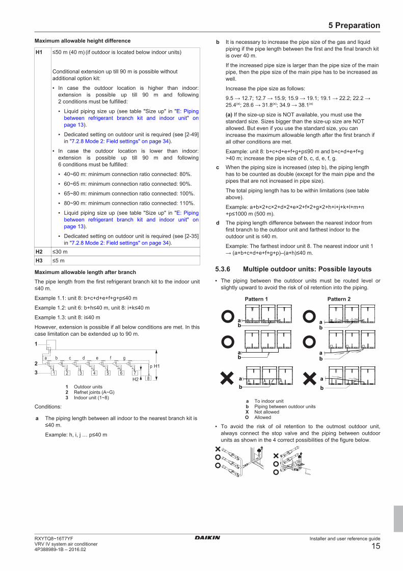
5.3.4 About the piping lengthMake sure to perform the piping installation within the range of themaximum allowable pipe length, allowable level difference andallowable length after branching as indicated below.
Definitions
Term DefinitionActual piping length Pipe length between outdoor(a) and indoor
units.Equivalent pipinglength(b)
Pipe length between outdoor(a) and indoorunits.
Total piping length Total piping length from the outdoor(a) to allindoor units.
H1 Difference in height between outdoor andindoor units.
H2 Difference in height between indoor andindoor units.
H3 Difference in height between outdoor andoutdoor units.
(a) If the system capacity is >16 HP, re-read "the first outdoorbranch as seen from the indoor unit".
(b) Assume equivalent piping length of refnet joint=0.5 m andrefnet header=1 m (for calculation purposes of equivalentpiping length, not for refrigerant charge calculations).
5.3.5 Piping length: VRV DX onlyFor system only containing VRV DX indoor units:
System setup
Example DescriptionExample 1.1
aA
h i j k l m nB C D E F G
p
b c d e f
1 2 3 4 5 6 78
gH1
H2
Single outdoor
Branch with refnet joint
Example 1.2
ab
c d e f
i
kj
g h
A B
1 2 3 4 5 6
7 8H1H2
Single outdoor
Branch with refnet jointand refnet header
Example 1.3
a
cb d e f ig h1 2 3 4 5 6 7
8
H1
H2
Single outdoor
Branch with refnetheader
Example 2.1
aA
h i j k l m nB C D E F G p
b c d e f
1 2 3 4 5 6 78
gtu
r s
H1
H3
Multi outdoor
Branch with refnet joint
Example 2.2
aj kb
1 2 3 4 5 6
7 8c d e f g h
tur s
BA H1
H3
H2
Multi outdoor
Branch with refnet jointand refnet header
Example DescriptionExample 2.3
a
b1 2 3 4 5 6 7
8
c d e f g h i
tur s
H1
H3
Multi outdoor
Branch with refnetheader
Example 3
r s
u
t
With standard multilayout
Indoor unitRefnet jointRefnet headerOutdoor multi connection piping kit
Maximum allowable length▪ Between outdoor and indoor units (single installation/multi
combinations)
Actual pipinglength
165 m/135 m
Example 1.1
▪ unit 8: a+b+c+d+e+f+g+p≤165 m
Example 1.2
▪ unit 6: a+b+h≤165 m
▪ unit 8: a+i+k≤165 m
Example 1.3
▪ unit 8: a+i≤165 m
Example 2.1
▪ unit 8: a+b+c+d+e+f+g+p≤135 mEquivalent length 190 m/160 mTotal pipinglength
1000 m/500 m
Example 1.1
▪ a+b+c+d+e+f+g+h+i+j+k+l+m+n+p≤1000 m
Example 2.1
▪ a+b+c+d+e+f+g+h+i+j+k+l+m+n+p≤500 m
▪ Between outdoor branch and outdoor unit (only in case >16 HP)
Actual pipinglength
10 m
Example 3
▪ r, s, t≤10 m; u≤5 mEquivalent length 13 m
5 Preparation
Installer and user reference guide
15RXYTQ8~16T7YFVRV IV system air conditioner4P388989-1B – 2016.02
Maximum allowable height difference
H1 ≤50 m (40 m) (if outdoor is located below indoor units)
Conditional extension up till 90 m is possible withoutadditional option kit:
▪ In case the outdoor location is higher than indoor:extension is possible up till 90 m and following2 conditions must be fulfilled:
▪ Liquid piping size up (see table "Size up" in "E: Pipingbetween refrigerant branch kit and indoor unit" onpage 13).
▪ Dedicated setting on outdoor unit is required (see [2‑49]in "7.2.8 Mode 2: Field settings" on page 34).
▪ In case the outdoor location is lower than indoor:extension is possible up till 90 m and following6 conditions must be fulfilled:
▪ 40~60 m: minimum connection ratio connected: 80%.
▪ 60~65 m: minimum connection ratio connected: 90%.
▪ 65~80 m: minimum connection ratio connected: 100%.
▪ 80~90 m: minimum connection ratio connected: 110%.
▪ Liquid piping size up (see table "Size up" in "E: Pipingbetween refrigerant branch kit and indoor unit" onpage 13).
▪ Dedicated setting on outdoor unit is required (see [2‑35]in "7.2.8 Mode 2: Field settings" on page 34).
H2 ≤30 mH3 ≤5 m
Maximum allowable length after branchThe pipe length from the first refrigerant branch kit to the indoor unit≤40 m.
Example 1.1: unit 8: b+c+d+e+f+g+p≤40 m
Example 1.2: unit 6: b+h≤40 m, unit 8: i+k≤40 m
Example 1.3: unit 8: i≤40 m
However, extension is possible if all below conditions are met. In thiscase limitation can be extended up to 90 m.
aA
h i j k l m nB C D E F G p
b c d e f
1 2 3 4 5 6 78
gH1
H2
1
23
1 Outdoor units2 Refnet joints (A~G)3 Indoor unit (1~8)
Conditions:
a The piping length between all indoor to the nearest branch kit is≤40 m.
Example: h, i, j … p≤40 m
b It is necessary to increase the pipe size of the gas and liquidpiping if the pipe length between the first and the final branch kitis over 40 m.
If the increased pipe size is larger than the pipe size of the mainpipe, then the pipe size of the main pipe has to be increased aswell.
(a) If the size-up size is NOT available, you must use thestandard size. Sizes bigger than the size-up size are NOTallowed. But even if you use the standard size, you canincrease the maximum allowable length after the first branch ifall other conditions are met.
Example: unit 8: b+c+d+e+f+g+p≤90 m and b+c+d+e+f+g>40 m; increase the pipe size of b, c, d, e, f, g.
c When the piping size is increased (step b), the piping lengthhas to be counted as double (except for the main pipe and thepipes that are not increased in pipe size).
The total piping length has to be within limitations (see tableabove).
Example: a+b×2+c×2+d×2+e×2+f×2+g×2+h+i+j+k+l+m+n+p≤1000 m (500 m).
d The piping length difference between the nearest indoor fromfirst branch to the outdoor unit and farthest indoor to theoutdoor unit is ≤40 m.
Example: The farthest indoor unit 8. The nearest indoor unit 1→ (a+b+c+d+e+f+g+p)–(a+h)≤40 m.
5.3.6 Multiple outdoor units: Possible layouts▪ The piping between the outdoor units must be routed level or
slightly upward to avoid the risk of oil retention into the piping.
Pattern 1 Pattern 2
ab
ba
ba
ab
ab b
a
a To indoor unitb Piping between outdoor unitsX Not allowedO Allowed
▪ To avoid the risk of oil retention to the outmost outdoor unit,always connect the stop valve and the piping between outdoorunits as shown in the 4 correct possibilities of the figure below.
6 Installation
Installer and user reference guide
16RXYTQ8~16T7YF
VRV IV system air conditioner4P388989-1B – 2016.02
ab b b
ab b b
a ba
b a b
aa a
≥200
mm
a To indoor unitb Oil collects to the outmost outdoor unit when the system
stopsX Not allowedO Allowed
▪ If the piping length between the outdoor units exceeds 2 m, createa rise of 200 mm or more in the gas line within a length of 2 mfrom the kit.
If Then≤2 m
ab
≤2 m
>2 m
a≤2 m ≤2 m
≥200
mm
≥200
mm
b
>2 m >2 m
a To indoor unitb Piping between outdoor units
NOTICE
There are restrictions on the refrigerant pipe connectionorder between outdoor units during installation in case of amultiple outdoor unit system. Install according to followingrestrictions. The capacities of outdoor units A, B and Cmust fulfill the following restriction conditions: A≥B≥C.
A B C
a b c
a To indoor units
b Outdoor unit multi connecting piping kit (first branch)
c Outdoor unit multi connecting piping kit (second branch)
5.4 Preparing electrical wiring
5.4.1 Safety device requirementsThe power supply must be protected with the required safetydevices, i.e. a main switch, a slow blow fuse on each phase and anearth leakage protector in accordance with the applicable legislation.
Selection and sizing of the wiring should be done in accordance withthe applicable legislation based on the information mentioned in thetable below.
Model Minimumcircuit
ampacity
Recommendedfuses
RXYTQ8 16.1 A 20 ARXYTQ10 22.0 A 25 ARXYTQ12 24.0 A 32 ARXYTQ14 27.0 A 32 ARXYTQ16 31.0 A 40 A
What? Case 1 Case 2Phase and frequency 3N~ 50 Hz 3N~ 60 HzVoltage 380-415 V 400 VTransmission linesection(1)
0.75~1.25 mm2
For multi combinationsCalculate the recommended fuse capacity
Formula Calculate, by adding the minimum circuit amps of eachused unit (according to the table above), multiply theresult by 1.1 and select the next higher recommendedfuse capacity.
Example Combining the RXYTQ30 by using the RXYTQ8,RXYTQ10, and RXYTQ12.
▪ Minimum circuit ampacity of the RXYTQ8=16.1 A
▪ Minimum circuit ampacity of the RXYTQ10=22.0 A
▪ Minimum circuit ampacity of the RXYTQ12=24.0 A
Accordingly, the minimum circuit ampacity of theRXYTQ30=16.1+22.0+24.0=62.1 A
Multiplying the above result by 1.1 (62.1×1.1)=68.31 A,so the recommended fuse capacity would be 80 A.
NOTICE
When using residual current operated circuit breakers, besure to use a high-speed type 300 mA rated residualoperating current.
6 Installation
6.1 Overview: InstallationThis chapter describes what you have to do and know on-site toinstall the system.
It contains information about:
▪ Opening the units
▪ Mounting the outdoor unit
▪ Connecting the refrigerant piping
▪ Checking the refrigerant piping
▪ Charging refrigerant
(1) Maximum length is 1000 m. If the total transmission wiring exceeds these limits, it may result in communication error.
6 Installation
Installer and user reference guide
17RXYTQ8~16T7YFVRV IV system air conditioner4P388989-1B – 2016.02
▪ Connecting the electrical wiring
6.2 Opening the units
6.2.1 To open the outdoor unit
DANGER: RISK OF ELECTROCUTION
DANGER: RISK OF BURNING
To gain access to the unit, front plates need to be opened as follows:
14×14×
8 HP 10~16 HP
Once the front plates open, the electrical component box can beaccessed. See "6.2.2 To open the electrical component box of theoutdoor unit" on page 17.
For service purposes, the push buttons on the main PCB need to beaccessed. To access these push buttons, the electrical componentbox cover does not need to be opened. See "7.2.3 To access thefield setting components" on page 31.
6.2.2 To open the electrical component box ofthe outdoor unit
NOTICE
Do not apply excessive force when opening the electroniccomponent box cover. Excessive force can deform thecover, resulting in entering of water to cause equipmentfailure.
2×
8 HP
SW8
6×
10~16 HP
SW8
NOTICE
When closing the electrical component box cover, makesure that the sealing material on the lower back side of thecover is not caught and bend towards the inside.
abc
de
a Electrical component box cover
b Front side
c Power supply terminal block
d Sealing material
e Moisture and dirt could enter
X Not allowed
O Allowed
6.3 Mounting the outdoor unit
6.3.1 To provide the installation structureMake sure the unit is installed level on a sufficiently strong base toprevent vibration and noise.
NOTICE
When the installation height of the unit needs to beincreased, do not use stands to only support the corners.
≥100 mm
≥100 mm
*X Not allowedO Allowed (* = preferred installation)
▪ The height of the foundation must at least be 150 mm from thefloor. In heavy snowfall areas, this height should be increased,depending on the installation place and condition.
▪ The preferred installation is on a solid longitudinal foundation(steel beam frame or concrete). The foundation must be largerthan the grey marked area.
729
≤613
≥929
≥ABAA
a (mm)Minimum foundation
a Anchor point (4×)
HP AA AB8 766 992
10~16 1076 1302
▪ Fasten the unit in place using four foundation bolts M12. It is bestto screw in the foundation bolts until their length remains 20 mmabove the foundation surface.
6 Installation
Installer and user reference guide
18RXYTQ8~16T7YF
VRV IV system air conditioner4P388989-1B – 2016.02
20 m
m
NOTICE
▪ Prepare a water drainage channel around thefoundation to drain waste water from around the unit.During heating operation and when the outdoortemperatures are negative, the drained water from theoutdoor unit will freeze up. If the water drainage is nottaken care of, the area around the unit might be veryslippery.
▪ When installed in a corrosive environment, use a nutwith plastic washer (a) to protect the nut tightening partfrom rust.
a
6.4 Connecting the refrigerant piping
6.4.1 Precautions when connecting refrigerantpiping
NOTICE
Make sure refrigerant piping installation complies withapplicable legislation. In Europe, EN378 is the applicablestandard.
NOTICE
Make sure the field piping and connections are notsubjected to stress.
WARNING
During tests, NEVER pressurize the product with apressure higher than the maximum allowable pressure (asindicated on the nameplate of the unit).
WARNING
Take sufficient precautions in case of refrigerant leakage. Ifrefrigerant gas leaks, ventilate the area immediately.Possible risks:
▪ Excessive refrigerant concentrations in a closed roomcan lead to oxygen deficiency.
▪ Toxic gas may be produced if refrigerant gas comesinto contact with fire.
WARNING
Always recover the refrigerant. Do NOT release themdirectly into the environment. Use a vacuum pump toevacuate the installation.
Only use phosphoric acid deoxidised seamless copper.
NOTICE
After all the piping has been connected, make sure there isno gas leak. Use nitrogen to perform a gas leak detection.
6.4.2 About connecting the refrigerant pipingBefore connecting the refrigerant piping, make sure the outdoor andindoor units are mounted.
Connecting the refrigerant piping involves:
▪ Routing and connecting the refrigerant piping to the outdoor unit
▪ Protecting the outdoor unit against contamination
▪ Connecting the refrigerant piping to the indoor units (see theinstallation manual of the indoor units)
▪ Connecting the multi-connection piping kit
▪ Connecting the refrigerant branching kit
▪ Keeping in mind the guidelines for:
▪ Brazing
▪ Using the stop valves
▪ Removing the pinched pipes
6.4.3 To route the refrigerant pipingInstallation of refrigerant piping is possible as front connection orside connection (when taken out from the bottom) as shown in thefigure below.
a b
c
a Left-side connectionb Front connectionc Right-side connection
For side connections, the knockout hole on the bottom plate shouldbe removed:
c
ba
a Large knockout holeb Drillc Points for drilling
NOTICE
Precautions when making knockout holes:
▪ Avoid damaging the casing.
▪ After making the knockout holes, we recommend youremove the burrs and paint the edges and areasaround the edges using repair paint to prevent rusting.
▪ When passing electrical wiring through the knockoutholes, wrap the wiring with protective tape to preventdamage.
6.4.4 To connect the refrigerant piping to theoutdoor unit
INFORMATION
All local inter unit piping are field supplied except theaccessory pipes.
6 Installation
Installer and user reference guide
19RXYTQ8~16T7YFVRV IV system air conditioner4P388989-1B – 2016.02
NOTICE
Precautions when connecting field piping. Add brazingmaterial as shown in the figure.
1 1
11
2 2
≤Ø25.4 >Ø25.4
NOTICE
▪ Be sure to use the supplied accessory pipes whencarrying out piping work in the field.
▪ Be sure that the field installed piping does not touchother pipes, the bottom panel or side panel. Especiallyfor the bottom and side connection, be sure to protectthe piping with suitable insulation, to prevent it fromcoming into contact with the casing.
Connection from the stop valves to the field piping can be done byusing accessory pipes supplied as accessory.
The connections to the branch kits are the responsibility of theinstaller (field piping).
6.4.5 To connect the multi connection piping kit
NOTICE
Improper installation may lead to malfunction of theoutdoor unit.
▪ Install the joints horizontally, so that the caution label (a) attachedto the joint comes to the top.
▪ Do not tilt the joint more than 7.5° (see view A).
▪ Do not install the joint vertically (see view B).
a a
A B7.5°7.5°
a Caution labelX Not allowedO Allowed
▪ Make sure that the total length of the piping connected to the jointis absolute straight for more than 500 mm. Only if a straight fieldpiping of more than 120 mm is connected, more than 500 mm ofstraight section can be ensured.
>120 mm>500 mm
6.4.6 Multiple outdoor units: Knockout holes
Connection DescriptionFront connection Remove the front plate knockout holes to
connect.
Bottom connection Remove the knockout holes on the bottomframe and route the piping under the bottom.
6.4.7 To connect the refrigerant branching kitFor installation of the refrigerant branching kit, refer to the installationmanual delivered with the kit.
▪ Mount the refnet joint so that it branches either horizontally orvertically.
▪ Mount the refnet header so that it branches horizontally.
6.4.8 To protect against contaminationProtect the piping as described in the following table to prevent dirt,liquid or dust from entering the piping.
Unit Installation period Protection methodOutdoor unit >1 month Pinch the pipe
<1 month Pinch or tape the pipeIndoor unit Regardless of the
period
Block all gaps in the holes for passing out piping and wiring usingsealing material (field supply) (otherwise the capacity of the unit willdrop and small animals may enter the machine).
Example: passing piping out through the front.
6 Installation
Installer and user reference guide
20RXYTQ8~16T7YF
VRV IV system air conditioner4P388989-1B – 2016.02
a
a Close the areas marked with " ". (When the piping isrouted from the front panel.)
▪ Only use clean pipes.
▪ Hold the pipe end downwards when removing burrs.
▪ Cover the pipe end when inserting it through a wall, to preventdust and/or particles entering the pipe.
6.4.9 To braze the pipe end▪ When brazing, blow through with nitrogen to prevent creation of
large quantities of oxidised film on the inside of the piping. Thisfilm adversely affects valves and compressors in the refrigeratingsystem and prevents proper operation.
▪ Set the nitrogen pressure to 20 kPa (just enough so it can be felton the skin) with a pressure-reducing valve.
a b c d e
ff
a Refrigerant pipingb Part to be brazedc Tapingd Manual valvee Pressure-reducing valvef Nitrogen
▪ Do NOT use anti-oxidants when brazing pipe joints.Residue can clog pipes and break equipment.
▪ Do NOT use flux when brazing copper-to-copper refrigerantpiping. Use phosphor copper brazing filler alloy (BCuP), whichdoes not require flux.Flux has an extremely harmful influence on refrigerant pipingsystems. For instance, if chlorine based flux is used, it will causepipe corrosion or, in particular, if the flux contains fluorine, it willdeteriorate the refrigerant oil.
6.4.10 Using the stop valve and service port
To handle the stop valve▪ Make sure to keep all stop valves open during operation.
▪ The figure below shows the name of each part required inhandling the stop valve.
▪ The stop valve is factory closed.
c
d
a
b
a Service port and service port coverb Stop valvec Field piping connectiond Stop valve cover
a b
cdea Service portb Stop valve coverc Hexagon holed Shafte Seal
To open the stop valve1 Remove the stop valve cover.
2 Insert a hexagon wrench into the stop valve and turn the stopvalve counterclockwise.
3 When the stop valve cannot be turned any further, stop turning.
Result: The valve is now open.
To fully open the Ø19.1 mm~Ø25.4 mm stop valve, turn thehexagonal wrench until a torque between 27 and 33 N•m isachieved.
Inadequate torque may cause leakage of refrigerant and breakage ofthe stop valve cap.
1
23
4
NOTICE
Pay attention that mentioned torque range is applicable foropening Ø19.1~Ø25.4 mm stop valves only.
To close the stop valve1 Remove the stop valve cover.
2 Insert a hexagon wrench into the stop valve and turn the stopvalve clockwise.
3 When the stop valve cannot be turned any further, stop turning.
Result: The valve is now closed.
Closing direction:
To handle the stop valve cover▪ The stop valve cover is sealed where indicated by the arrow. Take
care not to damage it.
▪ After handling the stop valve, make sure to tighten the stop valvecover securely. For the tightening torque, refer to the table below.
▪ Check for refrigerant leaks after tightening the stop valve cover.
6 Installation
Installer and user reference guide
21RXYTQ8~16T7YFVRV IV system air conditioner4P388989-1B – 2016.02
To handle the service port▪ Always use a charge hose equipped with a valve depressor pin,
since the service port is a Schrader type valve.
▪ After handling the service port, make sure to tighten the serviceport cover securely. For the tightening torque, refer to the tablebelow.
▪ Check for refrigerant leaks after tightening the service port cover.
Tightening torques
Stop valvesize (mm)
Tightening torque N•m (turn clockwise to close)Shaft
Valve body Hexagonalwrench
Cap (valvelid)
Serviceport
Ø9.5 5.4~6.6 4 mm 13.5~16.5 11.5~13.9Ø12.7 8.1~9.9 18.0~22.0Ø15.9 13.5~16.5 6 mm 23.0~27.0Ø19.1 27.0~33.0 8 mm 22.5~27.5Ø25.4
6.4.11 To remove the pinched pipes
WARNING
Any gas or oil remaining inside the stop valve may blow offthe pinched piping.
Failure to observe the instructions in procedure belowproperly may result in property damage or personal injury,which may be serious depending on the circumstances.
Use the following procedure to remove the pinched piping:
1 Remove the valve cover and make sure that the stop valves arefully closed.
c
d
a
b
a Service port and service port coverb Stop valvec Field piping connectiond Stop valve cover
2 Connect the vacuuming/recovery unit through a manifold to theservice port of all stop valves.
p< p>
R410AN2
b c e
a f gd
A B
a Pressure reducing valveb Nitrogenc Weighing scalesd Refrigerant R410A tank (siphon system)e Vacuum pumpf Liquid line stop valveg Gas line stop valveA Valve A
B Valve B
3 Recover gas and oil from the pinched piping by using arecovery unit.
CAUTION
Do not vent gases into the atmosphere.
4 When all gas and oil is recovered from the pinched piping,disconnect the charge hose and close the service ports.
5 Cut off the lower part of the gas, liquid and equalising stopvalve pipes along the black line. Use an appropriate tool (e.g. apipe cutter, a pair of nippers).
WARNING
Never remove the pinched piping by brazing.
Any gas or oil remaining inside the stop valve may blow offthe pinched piping.
6 Wait until all oil is dripped out before continuing with theconnection of the field piping in case the recovery was notcomplete.
6.5 Checking the refrigerant piping
6.5.1 About checking the refrigerant pipingRefrigerant piping works are finished?
The indoor units and/or outdoor unit were already powered ON?
Use procedure:"Method 2: After power ON".
Finish piping work.
Use procedure:"Method 1: Before power ON (regular method)".
Yes
No
No
Yes
It is very important that all refrigerant piping work is done before theunits (outdoor or indoor) are powered on.
When the units are powered on, the expansion valves will initialise.This means that they will close. Leak test and vacuum drying of fieldpiping and indoor units is impossible when this happens.
Therefore, there will be explained 2 methods for initial installation,leak test and vacuum drying.
6 Installation
Installer and user reference guide
22RXYTQ8~16T7YF
VRV IV system air conditioner4P388989-1B – 2016.02
Method 1: Before power ONIf the system has not yet been powered on, no special action isrequired to perform the leak test and the vacuum drying.
Method 2: After power ONIf the system has already been powered on, activate setting [2‑21](refer to "7.2.4 To access mode 1 or 2" on page 32). This settingwill open field expansion valves to guarantee a R410A pipingpathway and make it possible to perform the leak test and thevacuum drying.
NOTICE
Make sure that all indoor units connected to the outdoorunit are powered on.
NOTICE
Wait until the outdoor unit has finished the initialisation toapply setting [2‑21].
Leak test and vacuum dryingChecking the refrigerant piping involves:
▪ Checking for any leakages in the refrigerant piping.
▪ Performing vacuum drying to remove all moisture, air or nitrogenin the refrigerant piping.
If there is a possibility of moisture being present in the refrigerantpiping (for example, water may have entered the piping), first carryout the vacuum drying procedure below until all moisture has beenremoved.
All piping inside the unit has been factory tested for leaks.
Only field installed refrigerant piping needs to be checked.Therefore, make sure that all the outdoor unit stop valves are firmlyclosed before performing leak test or vacuum drying.
NOTICE
Make sure that all (field supplied) field piping valves areOPEN (not outdoor unit stop valves!) before you start leaktest and vacuuming.
For more information on the state of the valves, refer to"6.5.3 Checking refrigerant piping: Setup" on page 22.
Connect the vacuum pump through a manifold to the service port ofall stop valves to increase efficiency (refer to "6.5.3 Checkingrefrigerant piping: Setup" on page 22).
NOTICE
Use a 2-stage vacuum pump with a non-return valve or asolenoid valve that can evacuate to a gauge pressure of–100.7 kPa (5 Torr absolute).
NOTICE
Make sure the pump oil does not flow oppositely into thesystem while the pump is not working.
NOTICE
Do not purge the air with refrigerants. Use a vacuum pumpto evacuate the installation.
6.5.3 Checking refrigerant piping: Setupp< p>
R410AN2
C
b c e
agf
d
A B
a Pressure reducing valveb Nitrogenc Weighing scalesd Refrigerant R410A tank (siphon system)e Vacuum pumpf Liquid line stop valveg Gas line stop valveA Valve AB Valve BC Valve C
Valve State of valveValve A OpenValve B OpenValve C OpenLiquid line stop valve CloseGas line stop valve Close
NOTICE
The connections to the indoor units and all indoor unitsshould also be leak and vacuum tested. Keep any possible(field supplied) field piping valves open as well.
Refer to the indoor unit installation manual for more details.Leak test and vacuum drying should be done before thepower supply is set to the unit. If not, see also the flowchart earlier described in this chapter (see "6.5.1 Aboutchecking the refrigerant piping" on page 21).
6.5.4 To perform a leak testThe leak test must satisfy the specifications of EN378‑2.
To check for leaks: Vacuum leak test1 Evacuate the system from the liquid and gas piping to
–100.7 kPa (–1.007 bar/5 Torr) for more than 2 hours.
2 Once reached, turn off the vacuum pump and check that thepressure does not rise for at least 1 minute.
3 Should the pressure rise, the system may either containmoisture (see vacuum drying below) or have leaks.
To check for leaks: Pressure leak test1 Break the vacuum by pressurising with nitrogen gas to a
minimum gauge pressure of 0.2 MPa (2 bar). Never set thegauge pressure higher than the maximum operation pressure ofthe unit, i.e. 4.0 MPa (40 bar).
2 Test for leaks by applying a bubble test solution to all pipingconnections.
3 Discharge all nitrogen gas.
NOTICE
Make sure to use a recommended bubble test solutionfrom your wholesaler. Do not use soap water, which maycause cracking of flare nuts (soap water may contain salt,which absorbs moisture that will freeze when the pipinggets cold), and/or lead to corrosion of flared joints (soapwater may contain ammonia which causes a corrosiveeffect between the brass flare nut and the copper flare).
6 Installation
Installer and user reference guide
23RXYTQ8~16T7YFVRV IV system air conditioner4P388989-1B – 2016.02
6.5.5 To perform vacuum drying
NOTICE
The connections to the indoor units and all indoor unitsshould also be leak and vacuum tested. Keep, if existing,all (field supplied) field valves to the indoor units open aswell.
Leak test and vacuum drying should be done before thepower supply is set to the unit. If not, see "6.5.1 Aboutchecking the refrigerant piping" on page 21 for moreinformation.
To remove all moisture from the system, proceed as follows:
1 Evacuate the system for at least 2 hours to a target vacuum of–100.7 kPa (–1.007 bar/5 Torr).
2 Check that, with the vacuum pump turned off, the targetvacuum is maintained for at least 1 hour.
3 Should you fail to reach the target vacuum within 2 hours ormaintain the vacuum for 1 hour, the system may contain toomuch moisture. In that case, break the vacuum by pressurisingwith nitrogen gas to a gauge pressure of 0.05 MPa (0.5 bar)and repeat steps 1 to 3 until all moisture has been removed.
4 Depending on whether you want to immediately chargerefrigerant through the refrigerant charge port or first pre-chargea portion of refrigerant through the liquid line, either open theoutdoor unit stop valves, or keep them closed. See "6.7.2 Aboutcharging refrigerant" on page 24 for more information.
INFORMATION
After opening the stop valve, it is possible that the pressurein the refrigerant piping does NOT increase. This might becaused by e.g. the closed state of the expansion valve inthe outdoor unit circuit, but does NOT present any problemfor correct operation of the unit.
6.6 To insulate the refrigerant pipingAfter finishing the leak test and vacuum drying, the piping must beinsulated. Take into account the following points:
▪ Make sure to insulate the connection piping and refrigerant branchkits entirely.
▪ Be sure to insulate the liquid and gas piping (for all units).
▪ Use heat resistant polyethylene foam which can withstand atemperature of 70°C for liquid piping and polyethylene foam whichcan withstand a temperature of 120°C for gas piping.
▪ Reinforce the insulation on the refrigerant piping according to theinstallation environment.
Ambienttemperature
Humidity Minimum thickness
≤30°C 75% to 80% RH 15 mm>30°C ≥80% RH 20 mm
Condensation might form on the surface of the insulation.
▪ If there is a possibility that condensation on the stop valve mightdrip down into the indoor unit through gaps in the insulation andpiping because the outdoor unit is located higher than the indoorunit, this must be prevented by sealing up the connections. Seebelow figure.
b
a
a Insulation materialb Caulking etc.
6.7 Charging refrigerant
6.7.1 Precautions when charging refrigerant
WARNING
▪ Only use R410A as refrigerant. Other substances maycause explosions and accidents.
▪ R410A contains fluorinated greenhouse gases. Itsglobal warming potential (GWP) value is 2087.5. DoNOT vent these gases into the atmosphere.
▪ When charging refrigerant, always use protectivegloves and safety glasses.
NOTICE
If the power of some units is turned off, the chargingprocedure cannot be finished properly.
NOTICE
In case of a multiple outdoor system, turn on the power ofall outdoor units.
NOTICE
Be sure to turn on the power 6 hours before operation inorder to have power running to the crankcase heater andto protect the compressor.
NOTICE
If operation is performed within 12 minutes after the indoorand outdoor units are turned on, the compressor will notoperate before the communication is established in acorrect way between outdoor unit(s) and indoor units.
NOTICE
Before starting charging procedures, check if the7‑segment display indication of the outdoor unit A1P PCBis as normal (see "7.2.4 To access mode 1 or 2" onpage 32). If a malfunction code is present, see"10.2 Solving problems based on error codes" onpage 41.
NOTICE
Make sure all connected indoor units are recognised (see[1‑10] in "7.2.7 Mode 1: Monitoring settings" on page 33).
NOTICE
Close the front panel before any refrigerant chargeoperation is executed. Without the front panel attached theunit cannot judge correctly whether it is operating properlyor not.
6 Installation
Installer and user reference guide
24RXYTQ8~16T7YF
VRV IV system air conditioner4P388989-1B – 2016.02
NOTICE
In case of maintenance and the system (outdoor unit+fieldpiping+indoor units) does not contain any refrigerant anymore (e.g., after refrigerant reclaim operation), the unit hasto be charged with its original amount of refrigerant (referto the nameplate on the unit) by pre-charging before theautomatic charging function can be started.
6.7.2 About charging refrigerantOnce vacuum drying is finished, additional refrigerant charging canstart.
To speed up the refrigerant charging process, it is in case of largersystems recommended to first pre-charge a portion of refrigerantthrough the liquid line before proceeding with the manual charging.This step is included in below procedure (see "6.7.5 To chargerefrigerant" on page 26). It can be skipped, but charging will takelonger then.
A flow chart is available which gives an overview of the possibilitiesand actions to be taken (see "6.7.4 To charge refrigerant: Flowchart" on page 24).
6.7.3 To determine the additional refrigerantamount
NOTICE
The refrigerant charge of the system must be less than100 kg. This means that in case the calculated totalrefrigerant charge is equal to or more than 95 kg you mustdivide your multiple outdoor system into smallerindependent systems, each containing less than 95 kgrefrigerant charge. For factory charge, refer to the unitname plate.
Additional refrigerant to be charged=R (kg). R should be rounded offin units of 0.1 kg.
X1...6 =Total length (m) of liquid piping size at Øa
Piping length Total indoor unitcapacity CR(a)
A parameter (kg)8 HP 10+12 HP 14+16 HP
≤30 m 50%≤CR≤105% 0 1105%<CR≤130% 0.5 1.5
Piping length Total indoor unitcapacity CR(a)
A parameter (kg)8 HP 10+12 HP 14+16 HP
>30 m 50%≤CR≤70% 0 170%<CR≤85% 0.3 0.5 1.5
85%<CR≤105% 0.7 1 2105%<CR≤130% 1.2 1.5
(a) CR=Connection ratio.
INFORMATION
▪ When using multi combinations, add the sum ofindividual HP modules.
▪ Piping length is considered the distance from theoutdoor unit to the farthest indoor unit.
When using metric piping, please take into account following tableconcerning the weight factor to be allocated. It should be substitutedin the formula for R.
When selecting indoor unit, following table with connection ratiolimitation has to be respected. More detailed information can befound in technical engineering data.
Used indoor units Total capacity
CR(a)
Allowable capacityconnection ratio
VRV DXVRV DX 50~130% 50~130%
(a) CR=Connection ratio.
INFORMATION
For final charge adjustment in the test laboratory, pleasecontact your local dealer.
6.7.4 To charge refrigerant: Flow chart
For more information, see "6.7.5 To charge refrigerant" on page 26.
6 Installation
Installer and user reference guide
25RXYTQ8~16T7YFVRV IV system air conditioner4P388989-1B – 2016.02
Pre-charging refrigerantStep 1Calculate additional refrigerant charge amount: R (kg)
Refrigerant overcharge happened, recover refrigerant to reach R=Q
Step 2• Open valves C and B to the liquid line• Execute pre-charging amount: Q (kg)
Step 3a• Close valves C and B• Charging is finished• Fill in the amount on the additional
refrigerant charge label• Go to test run
Step 3bClose valves C and B
R=Q R>QR<Q
Continued on next page >>
p< p>
R410AN2
C
A B
Charging refrigerant
Step 5Proceed with manual charge
Step 6Activate field setting [2-20]=1Unit will start manual refrigerant charging operation.
Step 7• Open valve A• Charge remaining amount of refrigerant P (kg) R=Q+P
Step 8• Close valve A• Push BS3 to stop manual charging• Charging is finished• Fill in the amount on the additional refrigerant charge label• Go to test run
Step 4• Connect valve A to the refrigerant charge port (d)• Open all outdoor unit stop valves
R>Q
<< Continuation of previous page
p< p>
R410A
dA
6 Installation
Installer and user reference guide
26RXYTQ8~16T7YF
VRV IV system air conditioner4P388989-1B – 2016.02
6.7.5 To charge refrigerantFollow the steps as described below.
Pre-charging refrigerant1 Calculate the additional amount of refrigerant to be added using
the formula mentioned in "6.7.3 To determine the additionalrefrigerant amount" on page 24.
2 The first 10 kg of additional refrigerant can be pre-chargedwithout outdoor unit operation.
If ThenThe additional refrigerant amountis smaller than 10 kg
Perform steps 2+3.
The additional refrigerant chargeis larger than 10 kg
Perform steps 2~8.
3 Pre-charging can be done without compressor operation, byconnecting the refrigerant bottle to the service ports of the liquidand equalising stop valves (open valve B). Make sure that valveA and all outdoor unit stop valves are closed.
NOTICE
During pre-charging, the refrigerant is charged through theliquid line. Close valve A and disconnect the manifold fromthe gas line.
p< p>
R410AN2
C
b c e
agf
d
A B
a Pressure reducing valveb Nitrogenc Weighing scalesd Refrigerant R410A tank (siphon system)e Vacuum pumpf Liquid line stop valveg Gas line stop valveA Valve AB Valve BC Valve C
4 Do one of the following:
If Then4a The calculated additional
refrigerant amount is reachedby above pre-chargingprocedure
Close valves C and B anddisconnect the manifoldconnection to the liquid line.
4b The total amount ofrefrigerant could not becharged by pre-charging
Close valves C and B,disconnect the manifoldconnection to the liquid line,and perform steps 4~8.
INFORMATION
If the total additional refrigerant amount was reached instep 3 (by pre-charging only), record the amount ofrefrigerant that was added on the additional refrigerantcharge label provided with the unit and attach it on theback side of the front panel.
Perform the test procedure as described in"8 Commissioning" on page 38.
Charging refrigerant5 After pre-charging, connect valve A to the refrigerant charge
port and charge the remaining additional refrigerant through thisport. Open all outdoor unit stop valves. At this point, valve Amust remain closed!
p< p>
R410A
a c
db
A
a Weighing scalesb Refrigerant R410A tank (siphon system)c Vacuum pumpd Refrigerant charge portA Valve A
INFORMATION
For a multi outdoor unit system, it is not required toconnect all charge ports to a refrigerant tank.
The refrigerant will be charged with ±22 kg in 1 hour timeat an outdoor temperature of 30°C DB or with ±6 kg at anoutdoor temperature of 0°C DB.
If you need to speed up in case of a multiple outdoorsystem, connect the refrigerant tanks to each outdoor unit.
NOTICE
▪ The refrigerant charging port is connected to the pipinginside the unit. The unit's internal piping is alreadyfactory charged with refrigerant, so be careful whenconnecting the charge hose.
▪ After adding the refrigerant, do not forget to close thelid of the refrigerant charging port. The tighteningtorque for the lid is 11.5 to 13.9 N•m.
▪ In order to ensure uniform refrigerant distribution, itmay take the compressor ±10 minutes to start up afterthe unit has started operation. This is not a malfunction.
6 Proceed with the manual charge.
INFORMATION
After charging refrigerant:
▪ Record the additional refrigerant amount on therefrigerant label provided with the unit and attach it tothe backside of the front panel.
▪ Perform the test procedure described in"8 Commissioning" on page 38.
6.7.6 Step 6: To manually charge refrigerantThe remaining additional refrigerant charge can be charged byoperating the outdoor unit by means of the manual refrigerantcharge operation mode:
1 Take all the precautions mentioned in "7 Configuration" onpage 31 and "8 Commissioning" on page 38 into account.
2 Turn on the power of the indoor units and outdoor unit.
3 Activate outdoor unit setting [2‑20]=1 to start manual refrigerantcharge mode. Refer to "7.2.8 Mode 2: Field settings" onpage 34 for details.
Result: The unit will start operation.
4 Valve A can be opened. Charging of remaining additionalrefrigerant can be done.
5 When the remaining calculated additional refrigerant amount isadded, close valve A and push BS3 to stop the manualrefrigerant charging procedure.
6 Installation
Installer and user reference guide
27RXYTQ8~16T7YFVRV IV system air conditioner4P388989-1B – 2016.02
INFORMATION
The manual refrigerant charge operation will automaticallystop within 30 minutes. If charging is not completed after30 minutes, perform the additional refrigerant chargingoperation again.
6 Perform the test procedure as described in"8 Commissioning" on page 38.
INFORMATION
▪ When a malfunction is detected during the procedure(e.g., in case of closed stop valve), a malfunction codewill be displayed. In that case, refer to "6.7.7 Errorcodes when charging refrigerant" on page 27 andsolve the malfunction accordingly. Resetting themalfunction can be done by pushing BS3. Theprocedure can be restarted from "6.7.6 Step 6: Tomanually charge refrigerant" on page 26.
▪ Aborting the manual refrigerant charge is possible bypushing BS3. The unit will stop and return to idlecondition.
6.7.7 Error codes when charging refrigerantIf a malfunction occurs, close valve A immediately. Confirm themalfunction code and take corresponding action, "10.2 Solvingproblems based on error codes" on page 41.
6.7.8 Checks after charging refrigerant▪ Are all stop valves open?
▪ Is the amount of refrigerant, that has been added, recorded on therefrigerant charge label?
NOTICE
Make sure to open all stop valves after (pre-) charging therefrigerant.
Operating with the stop valves closed will damage thecompressor.
6.8 Connecting the electrical wiring
6.8.1 Precautions when connecting electricalwiring
DANGER: RISK OF ELECTROCUTION
WARNING
All field wiring and components must be installed by alicensed electrician and must comply with the applicablelegislation.
WARNING
If NOT factory installed, a main switch or other means fordisconnection, having a contact separation in all polesproviding full disconnection under overvoltage category IIIcondition, shall be installed in the fixed wiring.
WARNING
▪ ONLY use copper wires.
▪ Make sure the field wiring complies with the applicablelegislation.
▪ All field wiring must be performed in accordance withthe wiring diagram supplied with the product.
▪ NEVER squeeze bundled cables and make sure theydo not come in contact with the piping and sharpedges. Make sure no external pressure is applied to theterminal connections.
▪ Make sure to install earth wiring. Do NOT earth the unitto a utility pipe, surge absorber, or telephone earth.Incomplete earth may cause electrical shock.
▪ Make sure to use a dedicated power circuit. NEVERuse a power supply shared by another appliance.
▪ Make sure to install the required fuses or circuitbreakers.
▪ Make sure to install an earth leakage protector. Failureto do so may cause electric shock or fire.
▪ When installing the earth leakage protector, make sureit is compatible with the inverter (resistant to highfrequency electric noise) to avoid unnecessary openingof the earth leakage protector.
Install power cables at least 1 metre away from televisions or radiosto prevent interference. Depending on the radio waves, a distance of1 metre may not be sufficient.
WARNING
▪ After finishing the electrical work, confirm that eachelectrical component and terminal inside the electricalcomponents box is connected securely.
▪ Make sure all covers are closed before starting up theunit.
NOTICE
Do not operate the unit until the refrigerant piping iscomplete. Running the unit before the piping is ready willbreak the compressor.
NOTICE
If the power supply has a missing or wrong N-phase,equipment will break down.
NOTICE
Do NOT install a phase advancing capacitor, because thisunit is equipped with an inverter. A phase advancingcapacitor will reduce performance and may causeaccidents.
NOTICE
Never remove a thermistor, sensor, etc., when connectingpower wiring and transmission wiring. (If operated withoutthermistor, sensor, etc., the compressor may break down.)
NOTICE
▪ The reversed phase protection detector of this productonly functions when the product starts up.Consequently reversed phase detection is notperformed during normal operation of the product.
▪ The reversed phase protection detector is designed tostop the product in the event of an abnormality whenthe product is started up.
▪ Replace two of the three phases (L1, L2, and L3)during reverse-phase protection abnormality.
6 Installation
Installer and user reference guide
28RXYTQ8~16T7YF
VRV IV system air conditioner4P388989-1B – 2016.02
NOTICE
Only applicable if the power supply is three‑phase, and thecompressor has an ON/OFF starting method.
If there exists the possibility of reversed phase after amomentary black out and the power goes on and off whilethe product is operating, attach a reversed phaseprotection circuit locally. Running the product in reversedphase can break the compressor and other parts.
6.8.2 Field wiring: OverviewField wiring consists of power supply (always including earth) andindoor-outdoor communication (= transmission) wiring.
Example:a
b
dd d
c
b g gh h
c
fffh
eee
a
h h hh h
i
a Field power supply (with earth leakage protector)b Main switchc Earth connectiond Outdoor unite Indoor unitf User interfaceg Indoor power supply wiring (sheathed cable) (230 V)h Transmission wiring (sheathed cable) (16 V)i Outdoor power supply wiring (sheathed cable)
Power supply 3N~ 50/60 HzPower supply 1~ 50/60 HzEarth wiring
6.8.3 About the electrical wiringIt is important to keep the power supply and the transmission wiringseparated from each other. In order to avoid any electricalinterference the distance between both wiring should always be atleast 25 mm.
NOTICE
▪ Be sure to keep the power line and transmission lineapart from each other. Transmission wiring and powersupply wiring may cross, but may not run parallel.
▪ Transmission wiring and power supply wiring may nottouch internal piping (except the inverter PCB coolingpipe) in order to avoid wire damage due to hightemperature piping.
▪ Firmly close the lid and arrange the electrical wires soas to prevent the lid or other parts from coming loose.
The transmission wiring outside the unit should be wrapped androuted together with the field piping.
Field piping can be routed from front or bottom of the unit (going leftor right). Refer to "6.4.3 To route the refrigerant piping" on page 18.
▪ Be sure to follow the limits below. If the unit-to-unit cables arebeyond these limits, it may result in malfunction of transmission:
▪ Maximum wiring length: 1000 m.
▪ Total wiring length: 2000 m.
▪ Maximum inter unit wiring length between outdoor units: 30 m.
▪ Transmission wiring to cool/heat selector: 500 m.
▪ Maximum number of branches: 16.
▪ Maximum number of independent interconnectable systems: 10.
▪ Up to 16 branches are possible for unit-to-unit cabling. Nobranching is allowed after branching (see figure below).
a a a
A B
b
b
b
b
b
b
h
e
f
g
g
d
c
a Outdoor unitb Indoor unitc Main lined Branch line 1e Branch line 2f Branch line 3g No branch is allowed after branchh Central user interface (etc...)A Outdoor/indoor transmission wiringB Master/slave transmission wiring
For the above wiring, always use vinyl cords with 0.75 to 1.25 mm2
sheath or cables (2-core wires). (3-core wire cables are allowable forthe cooler/heater changeover user interface only.)
6.8.4 Guidelines when knocking out knockoutholes
▪ To punch a knockout hole, hit on it with a hammer.
▪ After knocking out the holes, we recommend removing any burrsand paint the edges and areas around the holes using repair paintto prevent rusting.
▪ When passing electrical wiring through the knockout holes.prevent damage to the wires by wrapping the wiring withprotective tape, putting the wires through field supplied protectivewire conduits at that location, or install suitable field supplied wirenipples or rubber bushings into the knockout holes.
a b c d
a Knockout holeb Burrc Remove burrsd If there are any possibilities that small animals enter the
system through the knockout holes, plug the holes withpacking materials (to be prepared on-site)
6.8.5 To route and fix the transmission wiringTransmission wiring can be routed through the front side only. Fix itto the upper mounting hole.
6 Installation
Installer and user reference guide
29RXYTQ8~16T7YFVRV IV system air conditioner4P388989-1B – 2016.02
b a
A
b a
c
c
c
d
c
d
c
8 HP 10~16 HP
A
Aa Transmission wiring (possibility 1)(a)
b Transmission wiring (possibility 2)(a). Fix to pipe insulationwith tie wraps.
c Tie wrap. Fix to factory-mounted low voltage wiring.d Tie wrap.
(a) Knockout hole has to be removed. Close the hole to avoidsmall animals or dirt from entering.
L1 L2 L3 N
c
d
c
d
d
d
c
c
a b a b8 HP 10~16 HP
Fix to the indicated plastic brackets using field supplied clampingmaterial.
a Wiring between the units (indoor-outdoor) (F1/F2 left)b Internal transmission wiring (Q1/Q2)c Plastic bracketd Field supplied clamps
6.8.6 To connect the transmission wiringThe wiring from the indoor units must be connected to the F1/F2(In‑Out) terminals on the PCB in the outdoor unit.
Tightening torque of the transmission wiring terminals:
a Outdoor unit PCB (A1P)b Use the conductor of sheathed wire (2 wire) (no polarity)c Terminal board (field supply)d Indoor unite Outdoor unit
In case of multi outdoor unit installation
F1 F2 F1 F2 Q1 Q2 Q1 Q2
A1P
d de f
ba c
Q1 Q2
a Unit A (master outdoor unit)b Unit B (slave outdoor unit)c Unit C (slave outdoor unit)d Master/slave transmission (Q1/Q2)e Outdoor/indoor transmission (F1/F2)f Outdoor unit/other system transmission (F1/F2)
▪ The interconnecting wiring between the outdoor units in the samepiping system must be connected to the Q1/Q2 (Out Multi)terminals. Connecting the wires to the F1/F2 terminals results insystem malfunction.
▪ The wiring for the other systems must be connected to the F1/F2(Out-Out) terminals of the PCB in the outdoor unit to which theinterconnecting wiring for the indoor units is connected.
▪ The base unit is the outdoor unit to which the interconnectingwiring for the indoor units is connected.
6.8.7 To finish the transmission wiringAfter installing the transmission wires inside the unit, wrap themalong with the on-site refrigerant pipes using finishing tape, asshown in figure below.
a bc de
a Liquid pipeb Gas pipec Insulatord Transmission wiring (F1/F2)e Finishing tape
6 Installation
Installer and user reference guide
30RXYTQ8~16T7YF
VRV IV system air conditioner4P388989-1B – 2016.02
6.8.8 To route and fix the power supply
NOTICE
When routing earth wires, secure clearance of 25 mm ormore away from compressor lead wires. Failure to observethis instruction properly may adversely affect correctoperation of other units connected to the same earth.
The power supply wiring can be routed from the front and left side.Fix it to the lower mounting hole.
d
c
X1M
ab
d
ac
d
X1M
b
8 HP 10~16 HP
A
AA
dd
a Power supply (possibility 1)(a)
b Power supply (possibility 2)(a)
c Power supply (possibility 3)(a). Use conduit.d Tie wrap
(a) Knockout hole has to be removed. Close the hole to avoidsmall animals or dirt from entering.
6.8.9 To connect the power supply
NOTICE
Never connect the power supply to transmission wiringterminal block. Otherwise the entire system may breakdown.
INFORMATION
Installation and routing in case the cool/heat selector isused: refer to the installation manual of the cool/heatselector.
CAUTION
When connecting the power supply, the earth connectionmust be made before the current-carrying connections areestablished. When disconnecting the power supply, thecurrent-carrying connections must be separated before theearth connection is. The length of the conductors betweenthe power supply stress relief and the terminal block itselfmust be as such that the current-carrying wires aretautened before the earth wire is in case the power supplyis pulled loose from the stress relief.
Wire it so that it comes through the cut out section of thecup washer. (An improper earth connection may prevent agood earthing from being achieved.)
The power supply must be clamped to the plastic bracket using fieldsupplied clamp material.
The green and yellow striped wire must be used for earthing only(refer to the figure below).
a bc d
f
g
e
jkhi
8 HP
a bc d
f
g
e
jkhi
10~16 HP
a Power supply (380~415 V - 3N~ 50Hz OR 400 V -3N~60 Hz)
b Fusec Earth leakage protectord Earth wiree Power supply terminal blockf Connect each power wire: RED to L1, WHT to L2, BLK to
L3 and BLU to Ng Earth wire (GRN/YLW)h Clamp the power supply to the plastic bracket using a field
supplied clamp to prevent external force being applied tothe terminal.
i Clamp (field supplied)j Cup washer
k When connecting the earth wire, it is recommended toperform curling.
Multiple outdoor unitsTo connect the power supply for multiple outdoor units to each other,ring tongues have to be used. No bare cable can be used.
The ring washer which is standard provided should be removed inthat case.
Attaching both cables to the power supply terminal should be doneas indicated.
L1 L2 L2 N
7 Configuration
Installer and user reference guide
31RXYTQ8~16T7YFVRV IV system air conditioner4P388989-1B – 2016.02
7 Configuration
7.1 Overview: ConfigurationThis chapter describes what you have to do and know to configurethe system after it is installed.
It contains information about:
▪ Making field settings
▪ Energy saving and optimum operation
INFORMATION
It is important that all information in this chapter is readsequentially by the installer and that the system isconfigured as applicable.
DANGER: RISK OF ELECTROCUTION
7.2 Making field settings
7.2.1 About making field settingsTo continue the configuration of the VRV IV heat pump system, it isrequired to give some input to the PCB of the unit. This chapter willdescribe how manual input is possible by operating the pushbuttons/DIP switches on the PCB and reading the feedback from the7‑segment displays.
Making settings is done via the master outdoor unit.
Next to making field settings it is also possible to confirm the currentoperation parameters of the unit.
Push buttons and DIP switches
Item DescriptionPush buttons By operating the push buttons it is possible to:
▪ Perform special actions (testrun, etc).
▪ Perform field settings (demand operation,low noise, etc).
DIP switches By operating the DIP switches it is possible to:
▪ DS1 (1): COOL/HEAT selector (refer to themanual of the cool/heat selector switch).OFF=not installed=factory setting
▪ DS1 (2~4): NOT USED. DO NOT CHANGETHE FACTORY SETTING.
▪ DS2 (1~4): NOT USED. DO NOT CHANGETHE FACTORY SETTING.
See also:
▪ "7.2.2 Field setting components" on page 31
▪ "7.2.3 To access the field setting components" on page 31
PC configuratorFor VRV IV heat pump system it is alternatively possible to makeseveral commissioning field settings through a personal computerinterface (for this, option EKPCCAB is required). The installer canprepare the configuration (off-site) on PC and afterwards upload theconfiguration to the system.
See also: "7.2.9 To connect the PC configurator to the outdoorunit" on page 36.
Mode 1 and 2
Mode DescriptionMode 1
(monitoringsettings)
Mode 1 can be used to monitor the currentsituation of the outdoor unit. Some field settingcontents can be monitored as well.
Mode 2
(field settings)
Mode 2 is used to change the field settings ofthe system. Consulting the current field settingvalue and changing the current field settingvalue is possible.
In general, normal operation can be resumedwithout special intervention after changing fieldsettings.
Some field settings are used for specialoperation (e.g., 1 time operation, recovery/vacuuming setting, manual adding refrigerantsetting, etc.). In such a case, it is required toabort the special operation before normaloperation can restart. It will be indicated inbelow explanations.
See also:
▪ "7.2.4 To access mode 1 or 2" on page 32
▪ "7.2.5 To use mode 1" on page 32
▪ "7.2.6 To use mode 2" on page 32
▪ "7.2.7 Mode 1: Monitoring settings" on page 33
▪ "7.2.8 Mode 2: Field settings" on page 34
7.2.2 Field setting componentsLocation of the 7‑segment displays, buttons and DIP switches:
a b
BS1 BS2 DS1 DS2BS3
X27A
BS1 MODE: For changing the set modeBS2 SET: For field settingBS3 RETURN: For field setting
7.2.3 To access the field setting componentsIt is not required to open the complete electronic component box toaccess the push buttons on the PCB and read out the 7‑segmentdisplay(s).
To access you can remove the front inspection cover of the frontplate (see figure). Now you can open the inspection cover of theelectrical component box front plate (see figure). You can see thethree push buttons and the 3 7‑segment displays and DIP switches.
2×
a
b
c
a Front plate
7 Configuration
Installer and user reference guide
32RXYTQ8~16T7YF
VRV IV system air conditioner4P388989-1B – 2016.02
b Main PCB with 3 7‑segment displays and 3 push buttonsc Electrical component box service cover
Operate the switches and push buttons with an insulated stick (suchas a closed ball-point pen) to avoid touching of live parts.
Make sure to re-attach the inspection cover into the electroniccomponent box cover and to close the front plate's inspection coverafter the job is finished. During operation of the unit the front plate ofthe unit should be attached. Settings are still possible to be madethrough the inspection opening.
NOTICE
Make sure that all outside panels, except for the servicecover on the electrical component box, are closed whileworking.
Close the lid of the electrical component box firmly beforeturning on the power.
7.2.4 To access mode 1 or 2Initialisation: default situation
NOTICE
Be sure to turn on the power 6 hours before operation inorder to have power running to the crankcase heater andto protect the compressor.
Turn on the power supply of the outdoor unit and all indoor units.When the communication between indoor units and outdoor unit(s) isestablished and normal, the 7‑segment display indication state willbe as below (default situation when shipped from factory).
Stage DisplayWhen turning on the power supply: flashing asindicated. First checks on power supply areexecuted (1~2 min).When no trouble occurs: lighted as indicated(8~10 min).Ready for operation: blank display indication asindicated.
7‑segment display indications:OffBlinkingOn
When above situation cannot be confirmed after 12 min, themalfunction code can be checked on the indoor unit user interfaceand the outdoor unit 7‑segment display. Solve the malfunction codeaccordingly. The communication wiring should be checked at first.
AccessBS1 is used to change the mode you want to access.
Access ActionMode 1 Push BS1 one time.
7‑segment display indication changes to:
Mode 2 Push BS1 for at least 5 seconds.
7‑segment display indication changes to:
INFORMATION
If you get confused in the middle of the process, push BS1.Then it returns to idle situation (no indication on 7‑segmentdisplays: blank, refer to "7.2.4 To access mode 1 or 2" onpage 32.
7.2.5 To use mode 1Mode 1 is used to set basic settings and to monitor the status of theunit.
What HowChanging and accessingthe setting in mode 1
Once mode 1 is selected (push BS1 1time), you can select the wanted setting.It is done by pushing BS2.
Accessing the selected setting's value isdone by pushing BS3 1 time.
To quit and return to theinitial status
Press BS1.
Example:Checking the content of parameter [1‑10] (to know how many indoorunits are connected to the system).
[A‑B]=C in this case defined as: A=1; B=10; C=the value we want toknow/monitor:
1 Make sure the 7‑segment display indication is as during normaloperation (default situation when shipped from factory).
2 Push BS1 1 time.
Result: Mode 1 is accessed:
3 Push BS2 10 times.
Result: Mode 1 setting 10 is addressed:
4 Push BS3 1 time; the value which is returned (depending on theactual field situation), is the amount of indoor units which areconnected to the system.
Result: Mode 1 setting 10 is addressed and selected, returnvalue is monitored information
5 To leave the monitoring function, push BS1 1 time.
Result: You will return to the default situation when shipped fromfactory.
7.2.6 To use mode 2The master unit should be used to input field settings inmode 2.
Mode 2 is used to set field settings of the outdoor unit and system.
What HowChanging and accessingthe setting in mode 2
Once mode 2 is selected (push BS1 formore than 5 seconds), you can selectthe wanted setting. It is done by pushingBS2.
Accessing the selected setting's value isdone by pushing BS3 1 time.
To quit and return to theinitial status
Press BS1.
7 Configuration
Installer and user reference guide
33RXYTQ8~16T7YFVRV IV system air conditioner4P388989-1B – 2016.02
What HowChanging the value of theselected setting in mode 2
▪ Once mode 2 is selected (push BS1for more than 5 seconds) you canselect the wanted setting. It is doneby pushing BS2.
▪ Accessing the selected setting's valueis done by pushing BS3 1 time.
▪ Now BS2 is used to select therequired value of the selected setting.
▪ When the required value is selected,you can define the change of valueby pushing BS3 1 time.
▪ Press BS3 again to start operationaccording to the chosen value.
Example:Checking the content of parameter [2‑18] (to define the high staticpressure setting of the outdoor unit's fan).
[A‑B]=C in this case defined as: A=2; B=18; C=the value we want toknow/change
1 Make sure the 7‑segment display indication is as during normaloperation (default situation when shipped from factory).
2 Push BS1 for over 5 seconds.
Result: Mode 2 is accessed:
3 Push BS2 18 times.
Result: Mode 2 setting 18 is addressed:
4 Push BS3 1 time; the value which is returned (depending on theactual field situation), is the status of the setting. In the case of[2‑18], default value is "0", which means the function is notactive.
Result: Mode 2 setting 18 is addressed and selected, returnvalue is the current setting situation.
5 To change the value of the setting, push BS2 till the requiredvalue appears on the 7‑segment display indication. Whenachieved, define the setting value by pushing BS3 1 time. Tostart operation according to the chosen setting, confirm againby pushing BS3.
6 To leave the monitoring function, push BS1 2 times.
Result: You will return to the default situation when shipped fromfactory.
7.2.7 Mode 1: Monitoring settings[1‑0]Shows whether the unit you check is a master, slave 1 or slave 2unit.
Master, slave 1 and slave 2 indications are relevant in multipleoutdoor unit system configurations. The allocation of which outdoorunit is master, slave 1 or slave 2 are decided by the unit's logic.
The master unit should be used to input field settings inmode 2.
0 Outdoor unit is master unit.1 Outdoor unit is slave 1 unit.2 Outdoor unit is slave 2 unit.
[1‑1]Shows the status of low noise operation.
Low noise operation reduces the sound generated by the unitcompared to nominal operating conditions.
[1‑1] Description0 Unit is currently not operating under low noise
restrictions.1 Unit is currently operating under low noise
restrictions.
Low noise operation can be set in mode 2. There are two methods toactivate low noise operation of the outdoor unit system.
▪ The first method is to enable an automatic low noise operationduring night time by field setting. The unit will operate at theselected low noise level during the selected time frames.
▪ The second method is to enable low noise operation based on anexternal input. For this operation an optional accessory isrequired.
[1‑2]Shows the status of power consumption limitation operation.
Power consumption limitation reduces the power consumption of theunit compared to nominal operating conditions.
[1‑2] Description0 Unit is currently not operating under power
consumption limitations.1 Unit is currently operating under power
consumption limitation.
Power consumption limitation can be set in mode 2. There are twomethods to activate power consumption limitation of the outdoor unitsystem.
▪ The first method is to enable a forced power consumptionlimitation by field setting. The unit will always operate at theselected power consumption limitation.
▪ The second method is to enable power consumption limitationbased on an external input. For this operation an optionalaccessory is required.
[1‑5] [1‑6]Shows:
▪ [1‑5]: The current Te target parameter position.
▪ [1‑6]: The current Tc target parameter position.
Refer to "7.3 Energy saving and optimum operation" on page 36 formore details about the contents of this value.
[1‑10]Shows the total number of connected indoor units.
It can be convenient to check if the total number of indoor unitswhich are installed match the total number of indoor units which arerecognised by the system. In case there is a mismatch, it isrecommended to check the communication wiring path betweenoutdoor and indoor units (F1/F2 communication line).
[1‑13]Shows the total number of connected outdoor units (in case ofmultiple outdoor system).
It can be convenient to check if the total number of outdoor unitswhich are installed matches the total number of outdoor units whichare recognised by the system. In case there is a mismatch, it isrecommended to check the communication wiring path betweenoutdoor and outdoor units (Q1/Q2 communication line).
[1‑17] [1‑18] [1‑19]Shows:
▪ [1‑17]: The latest malfunction code.
▪ [1‑18]: The 2nd last malfunction code.
7 Configuration
Installer and user reference guide
34RXYTQ8~16T7YF
VRV IV system air conditioner4P388989-1B – 2016.02
▪ [1‑19]: The 3rd last malfunction code.
When the latest malfunction codes were reset by accident on anindoor unit user interface, they can be checked again through thismonitoring settings.
For the content or reason behind the malfunction code see"10.2 Solving problems based on error codes" on page 41, wheremost relevant malfunction codes are explained. Detailed informationabout malfunction codes can be consulted in the service manual ofthis unit.
[1‑40] [1‑41]Shows:
▪ [1‑40]: The current cooling comfort setting.
▪ [1‑41]: The current heating comfort setting.
See "7.3 Energy saving and optimum operation" on page 36 formore details about this setting.
7.2.8 Mode 2: Field settings[2‑0]Cool/Heat selection setting.
Cool/Heat selection setting is used in case the optional Cool/Heatselector (KRC19-26A and BRP2A81) is used. Depending on theoutdoor unit setup (single outdoor unit setup or multi outdoor unitsetup), the correct setting should be chosen. More details on how touse the Cool/Heat selector option can be found in the manual of theCool/Heat selector.
[2‑0] Description0 (default) Each individual outdoor unit can select Cool/
Heat operation (by Cool/Heat selector ifinstalled), or by defining master indoor userinterface (see setting [2‑83] and the operationmanual).
1 Master unit decides Cool/Heat operation whenoutdoor units are connected in multiple systemcombination(a).
2 Slave unit for Cool/Heat operation whenoutdoor units are connected in multiple systemcombination(a).
(a) It is necessary to use the optional external control adaptorfor outdoor unit (DTA104A61/62). See the instructiondelivered with the adaptor for further details.
[2‑8]Te target temperature during cooling operation.
[2‑8] Te target (°C)0 (default) Auto
2 63 74 85 96 107 11
For more information and advice about the impact of these settings,see "7.3 Energy saving and optimum operation" on page 36.
[2‑9]Tc target temperature during heating operation.
[2‑9] Tc target (°C)0 (default) Auto
1 413 43
[2‑9] Tc target (°C)6 46
For more information and advice about the impact of these settings,see "7.3 Energy saving and optimum operation" on page 36.
[2‑12]Enable the low noise function and/or power consumption limitationvia external control adaptor (DTA104A61/62).
If the system needs to be running under low noise operation orunder power consumption limitation conditions when an externalsignal is sent to the unit, this setting should be changed. This settingwill only be effective when the optional external control adaptor(DTA104A61/62) is installed.
[2‑12] Description0 (default) Deactivated.
1 Activated.
[2‑18]Fan high static pressure setting.
In order to increase the static pressure the outdoor unit fan isdelivering, this setting should be activated. For details about thissetting, see technical specifications.
[2‑18] Description0 (default) Deactivated.
1 Activated.
[2‑20]Manual additional refrigerant charge.
In order to add the additional refrigerant charge amount in a manualway (without automatic refrigerant charging functionality), followingsetting should be applied. Further instructions regarding the differentways to charge additional refrigerant into your system can be foundin chapter "6.7.2 About charging refrigerant" on page 24.
[2‑20] Description0 (default) Deactivated.
1 Activated.
To stop the manual additional refrigerantcharge operation (when the required additionalrefrigerant amount is charged), push BS3. Ifthis function was not aborted by pushing BS3,the unit will stop its operation after 30 minutes.If 30 minutes was not sufficient to add theneeded refrigerant amount, the function can bereactivated by changing the field setting again.
[2‑21]Refrigerant recovery/vacuuming mode.
In order to achieve a free pathway to reclaim refrigerant out of thesystem or to remove residual substances or to vacuum the system itis necessary to apply a setting which will open required valves in therefrigerant circuit so the reclaim of refrigerant or vacuuming processcan be done properly.
[2‑21] Description0 (default) Deactivated.
1 Activated.
To stop the refrigerant recovery/vacuumingmode, push BS3. If BS3 is not pushed, thesystem will remain in refrigerant recovery/vacuuming mode.
[2‑22]Automatic low noise setting and level during night time.
7 Configuration
Installer and user reference guide
35RXYTQ8~16T7YFVRV IV system air conditioner4P388989-1B – 2016.02
By changing this setting, you activate the automatic low noiseoperation function of the unit and define the level of operation.Depending on the chosen level, the noise level will be lowered. Thestart and stop moments for this function are defined under setting[2‑26] and [2‑27].
[2‑25]Low noise operation level via the external control adaptor.
If the system needs to be running under low noise operationconditions when an external signal is sent to the unit, this settingdefines the level of low noise that will be applied.
This setting will only be effective when the optional external controladaptor (DTA104A61/62) is installed and the setting [2‑12] wasactivated.
This setting is used in conjunction with setting [2‑22].
[2‑26] Start time automatic low noise operation(approximately)
1 20h002 (default) 22h00
3 24h00
[2‑27]Low noise operation stop time.
This setting is used in conjunction with setting [2‑22].
[2‑27] Stop time automatic low noise operation(approximately)
1 6h002 7h00
3 (default) 8h00
[2‑30]Power consumption limitation level (step 1) via the external controladaptor (DTA104A61/62).
If the system needs to be running under power consumptionlimitation conditions when an external signal is sent to the unit, thissetting defines the level power consumption limitation that will beapplied for step 1. The level is according to the table.
[2‑30] Power consumption limitation(approximately)
1 60%2 65%
3 (default) 70%4 75%5 80%6 85%7 90%8 95%
[2‑31]Power consumption limitation level (step 2) via the external controladaptor (DTA104A61/62).
If the system needs to be running under power consumptionlimitation conditions when an external signal is sent to the unit, thissetting defines the level power consumption limitation that will beapplied for step 2. The level is according to the table.
[2‑31] Power consumption limitation(approximately)
1 (default) 40%2 50%3 55%
[2‑32]Forced, all time, power consumption limitation operation (no externalcontrol adaptor is required to perform power consumption limitation).
If the system always needs to be running under power consumptionlimitation conditions, this setting activates and defines the levelpower consumption limitation that will be applied continuously. Thelevel is according to the table.
[2‑32] Restriction reference0 (default) Function not active.
[2‑35] Description0 In case the outdoor unit is installed in the
lowest position (indoor units are installed on ahigher position than outdoor units) and theheight difference between the highest indoorunit and the outdoor unit exceeds 40 m, thesetting [2‑35] should be changed to 0.
1 (default) —
Other changes/limitations to the circuit apply, for more informationsee "5.3.5 Piping length: VRV DX only" on page 14.
[2‑49]Height difference setting.
[2‑49] Description0 (default) —
1 In case the outdoor unit is installed in thehighest position (indoor units are installed on alower position than outdoor units) and theheight difference between the lowest indoorunit and the outdoor unit exceeds 50 m, thesetting [2‑49] has to be changed to 1.
Other changes/limitations to the circuit apply, for more informationsee "5.3.5 Piping length: VRV DX only" on page 14.
[2‑81]Cooling comfort setting.
This setting is used in conjunction with setting [2‑8].
[2‑81] Cooling comfort setting0 Eco
1 (default) Mild2 Quick3 Powerful
7 Configuration
Installer and user reference guide
36RXYTQ8~16T7YF
VRV IV system air conditioner4P388989-1B – 2016.02
For more information and advice about the impact of these settings,see "7.3 Energy saving and optimum operation" on page 36.
[2‑82]Heating comfort setting.
This setting is used in conjunction with setting [2‑9].
[2‑82] Heating comfort setting0 Eco
1 (default) Mild2 Quick3 Powerful
For more information and advice about the impact of these settings,see "7.3 Energy saving and optimum operation" on page 36.
7.2.9 To connect the PC configurator to theoutdoor unit
X27A
a bc2
34
5
H JS
T
X27A
A1P
a PCb Cable (EKPCCAB)c Outdoor unit main PCB
7.3 Energy saving and optimumoperation
This heat pump system is equipped with advanced energy savingfunctionality. Depending on the priority, emphasises can be put onenergy saving or comfort level. Several parameters can be selected,resulting in the optimal balance between energy consumption andcomfort for the particular application.
Several patterns are available and explained below. Modify theparameters to the needs of your building and to realize the bestbalance between energy consumption and comfort.
No matter which control is selected, variations on the behaviour ofthe system are still possible due to protection controls to keep theunit operating under reliable conditions. The intentional target,however, is fixed and will be used to obtain the best balancebetween energy consumption and comfort, depending on theapplication type.
7.3.1 Available main operation methodsBasicThe refrigerant temperature is fixed independent from the situation. Itcorresponds to the standard operation which is known and can beexpected from/under previous VRV systems.
To activate this in… Change…Cooling operation [2‑8]=2Heating operation [2‑9]=6
AutomaticThe refrigerant temperature is set depending on the outdoor ambientconditions. As such adjusting the refrigerant temperature to matchthe required load (which is also related to the outdoor ambientconditions).
E.g., when your system is operating in cooling, you do not need asmuch cooling under low outdoor ambient temperatures (e.g., 25°C)as under high outdoor ambient temperatures (e.g., 35°C). Using thisidea, the system automatically starts increasing its refrigeranttemperature, automatically reducing the delivered capacity andincreasing the system's efficiency.
E.g., when your system is operating in heating, you do not need asmuch heating under high outdoor ambient temperatures (e.g., 15°C)as under low outdoor ambient temperatures (e.g., –5°C). Using thisidea, the system automatically starts decreasing its refrigeranttemperature, automatically reducing the delivered capacity andincreasing the system's efficiency.
To activate this in… Change…Cooling operation [2‑8]=0 (default)Heating operation [2‑9]=0 (default)
Hi-sensible/economic (cooling/heating)The refrigerant temperature is set higher/lower (cooling/heating)compared to basic operation. The focus under high sensible mode iscomfort feeling for the customer.
The selection method of indoor units is important and has to beconsidered as the available capacity is not the same as under basicoperation.
For details concerning to Hi-sensible applications, please contactyour dealer.
To activate this in… Change…Cooling operation [2‑8] to the appropriate value,
matching the requirements of thepre-designed system containinga high sensible solution.
Heating operation [2‑9] to the appropriate value,matching the requirements of thepre-designed system containinga high sensible solution.
[2‑8] Te target (°C)3 74 85 96 107 11
[2‑9] Tc target (°C)1 413 43
7.3.2 Available comfort settingsFor each of above modes a comfort level can be selected. Thecomfort level is related to the timing and the effort (energyconsumption) which is put in achieving a certain room temperatureby temporarily changing the refrigerant temperature to differentvalues in order to achieve requested conditions more quickly.
PowerfulOvershoot (during heating operation) or undershoot (during coolingoperation) is allowed compared to the requested refrigeranttemperature, in order to achieve the required room temperature veryfast. The overshoot is allowed from the start up moment.
7 Configuration
Installer and user reference guide
37RXYTQ8~16T7YFVRV IV system air conditioner4P388989-1B – 2016.02
▪ In case of cooling operation the evaporating temperature isallowed to go down to 3°C on temporary base depending on thesituation.
▪ In case of heating operation the condense temperature is allowedto go up to 49°C on temporary base depending on the situation.
▪ When the request from the indoor units becomes more moderate,the system will eventually go to the steady state condition which isdefined by the operation method above.
To activate this in… Change…Cooling operation [2‑81]=3.
This setting is used inconjunction with setting [2‑8].
Heating operation [2‑82]=3.
This setting is used inconjunction with setting [2‑9]
QuickOvershoot (during heating operation) or undershoot (during coolingoperation) is allowed compared to the requested refrigeranttemperature, in order to achieve the required room temperature veryfast. The overshoot is allowed from the start up moment.
▪ In case of cooling operation the evaporating temperature isallowed to go down to 6°C on temporary base depending on thesituation.
▪ In case of heating operation the condense temperature is allowedto go up to 46°C on temporary base depending on the situation.
▪ When the request from the indoor units becomes more moderate,the system will eventually go to the steady state condition which isdefined by the operation method above.
To activate this in… Change…Cooling operation [2‑81]=2.
This setting is used inconjunction with setting [2‑8].
Heating operation [2‑82]=2.
This setting is used inconjunction with setting [2‑9].
MildOvershoot (during heating operation) or undershoot (during coolingoperation) is allowed compared to the requested refrigeranttemperature, in order to achieve the required room temperature veryfast. The overshoot is not allowed from the start up moment. Thestart up occurs under the condition which is defined by the operationmode above.
▪ In case of cooling operation the evaporating temperature isallowed to go down to 6°C on temporary base depending on thesituation.
▪ In case of heating operation the condense temperature is allowedto go up to 46°C on temporary base depending on the situation.
▪ When the request from the indoor units becomes more moderate,the system will eventually go to the steady state condition which isdefined by the operation method above.
▪ The start up condition is different from the powerful and quickcomfort setting.
To activate this in… Change…Cooling operation [2‑81]=1.
This setting is used inconjunction with setting [2‑8].
Heating operation [2‑82]=1.
This setting is used inconjunction with setting [2‑9].
EcoThe original refrigerant temperature target, which is defined by theoperation method (see above) is kept without any correction, unlessfor protection control.
To activate this in… Change…Cooling operation [2‑81]=0.
This setting is used inconjunction with setting [2‑8].
Heating operation [2‑82]=0.
This setting is used inconjunction with setting [2‑9].
7.3.3 Example: Automatic mode during cooling
A
B
E
100%
50%
Te
C
D
3°C
6°C
35°C FA Actual load curveB Virtual load curve (initial capacity automatic mode)C Virtual target value (initial evaporation temperature value
automatic mode)D Required evaporation temperature valueE Load factorF Outside air temperature
Te Evaporating temperatureQuickPowerfulMild
8 Commissioning
Installer and user reference guide
38RXYTQ8~16T7YF
VRV IV system air conditioner4P388989-1B – 2016.02
Room temperature evolution:
A
B C
DE
F
A Indoor unit set temperatureB Operation startC Operating timeD MildE QuickF Powerful
7.3.4 Example: Automatic mode during heating
A
B
100%
70%
E
Tc
C
D
49°C
46°C
F2°C
A Virtual load curve (default automatic mode peak capacity)B Load curveC Virtual target value (initial condensation temperature value
automatic mode)D Design temperatureE Load factorF Outside air temperature
Tc Condensing temperatureQuickPowerfulMild
Room temperature evolution:
A
B C
D
EF
A Indoor unit set temperatureB Operation startC Operating timeD MildE QuickF Powerful
8 Commissioning
8.1 Overview: CommissioningAfter installation and once the field settings are defined, the installeris obliged to verify correct operation. Therefore a test run must beperformed according to the procedures described below.
This chapter describes what you have to do and know tocommission the system after it is configured.
Commissioning typically consists of the following stages:1 Checking the "Checklist before commissioning".2 Performing a test run.3 If necessary, correcting errors after abnormal completion of the
test run.4 Operating the system.
8.2 Precautions when commissioningDANGER: RISK OF ELECTROCUTION
DANGER: RISK OF BURNING
CAUTION
Do not perform the test operation while working on theindoor units.
When performing the test operation, not only the outdoorunit, but the connected indoor unit will operate as well.Working on an indoor unit while performing a test operationis dangerous.
CAUTION
Do not insert fingers, rods or other objects into the air inletor outlet. Do not remove the fan guard. When the fan isrotating at high speed, it will cause injury.
NOTICE
Test run is possible for ambient temperatures between 0°Cand 52°C.
8 Commissioning
Installer and user reference guide
39RXYTQ8~16T7YFVRV IV system air conditioner4P388989-1B – 2016.02
INFORMATION
Note that during the first running period of the unit,required power input may be higher. This phenomenonoriginates from the compressor that requires a 50 hour runelapse before reaching smooth operation and stable powerconsumption. Reason is that the scroll is made out of ironand that it takes some time to smooth the surfaces thatmake contact.
NOTICE
Be sure to turn on the power 6 hours before operation inorder to have power running to the crankcase heater andto protect the compressor.
During test operation, the outdoor unit and the indoor units will startup. Make sure that the preparations of all indoor units are finished(field piping, electrical wiring, air purge, ...). See installation manualof the indoor units for details.
8.3 Checklist before commissioningAfter the installation of the unit, first check the following items. Onceall below checks are fulfilled, the unit must be closed, only then canthe unit be powered up.
You read the complete installation and operationinstructions, as described in the installer and userreference guide.Installation
Check that the unit is properly installed, to avoid abnormalnoises and vibrations when starting up the unit.Field wiring
Be sure that the field wiring has been carried outaccording to the instructions described in the chapter"6.8 Connecting the electrical wiring" on page 27,according to the wiring diagrams and according to theapplicable legislation.Power supply voltage
Check the power supply voltage on the local supply panel.The voltage must correspond to the voltage on theidentification label of the unit.Earth wiring
Be sure that the earth wires have been connectedproperly and that the earth terminals are tightened.Insulation test of the main power circuit
Using a megatester for 500 V, check that the insulationresistance of 2 MΩ or more is attained by applying avoltage of 500 V DC between power terminals and earth.Never use the megatester for the transmission wiring.Fuses, circuit breakers, or protection devices
Check that the fuses, circuit breakers, or the locallyinstalled protection devices are of the size and typespecified in the chapter "5.4.1 Safety devicerequirements" on page 16. Be sure that neither a fuse nora protection device has been bypassed.Internal wiring
Visually check the electrical component box and theinside of the unit on loose connections or damagedelectrical components.Pipe size and pipe insulation
Be sure that correct pipe sizes are installed and that theinsulation work is properly executed.Stop valves
Be sure that the stop valves are open on both liquid andgas side.
Damaged equipment
Check the inside of the unit on damaged components orsqueezed pipes.Refrigerant leak
Check the inside of the unit on refrigerant leakage. If thereis a refrigerant leak, try to repair the leak. If the repair isunsuccessful, call your local dealer. Do not touch anyrefrigerant which has leaked out from refrigerant pipingconnections. This may result in frostbite.Oil leak
Check the compressor for oil leakage. If there is an oilleak, try to repair the leak. If the repairing is unsuccessful,call your local dealer.Air inlet/outlet
Check that the air inlet and outlet of the unit is notobstructed by paper sheets, cardboard, or any othermaterial.Additional refrigerant charge
The amount of refrigerant to be added to the unit shall bewritten on the included "Added refrigerant" plate andattached to the rear side of the front cover.Installation date and field setting
Be sure to keep record of the installation date on thesticker on the rear of the upper front panel according toEN60335‑2‑40 and keep record of the contents of the fieldsetting(s).
8.4 About test runThe procedure below describes the test operation of the completesystem. This operation checks and judges following items:
▪ Check of wrong wiring (communication check with indoor units).
▪ Check of the stop valves opening.
▪ Judgement of piping length.
▪ Make sure to carry out the system test operation after the firstinstallation. Otherwise, the malfunction code will be displayedon the user interface and normal operation or individual indoor unittest run cannot be carried out.
▪ Abnormalities on indoor units cannot be checked for each unitseparately. After the test operation is finished, check the indoorunits one by one by performing a normal operation using the userinterface. Refer to the indoor unit installation manual for moredetails concerning the individual test run.
INFORMATION
▪ It may take 10 minutes to achieve a uniform refrigerantstate before the compressor starts.
▪ During the test operation, the refrigerant running soundor the magnetic sound of a solenoid valve may becomeloud and the display indication may change. These arenot malfunctions.
8.5 To perform a test run1 Close all front panels in order to not let it be the cause of
misjudgement (except the electrical component box inspectionopening service cover).
2 Make sure all field settings you want are set; see "7.2 Makingfield settings" on page 31.
3 Turn ON the power to the outdoor unit and the connectedindoor units.
9 Maintenance and service
Installer and user reference guide
40RXYTQ8~16T7YF
VRV IV system air conditioner4P388989-1B – 2016.02
NOTICE
Be sure to turn on the power 6 hours before operation inorder to have power running to the crankcase heater andto protect the compressor.
4 Make sure the default (idle) situation is existing; see "7.2.4 Toaccess mode 1 or 2" on page 32. Push BS2 for 5 seconds ormore. The unit will start test operation.
Result: The test operation is automatically carried out, theoutdoor unit display will indicate " " and the indication "Testoperation" and "Under centralised control" will display on theuser interface of indoor units.
Steps during the automatic system test run procedure:
Step DescriptionControl before start up (pressure equalisation)Cooling start up controlCooling stable conditionCommunication checkStop valve checkPipe length checkRefrigerant amount checkPump down operationUnit stop
Note: During the test operation, it is not possible to stop the unitoperation from a user interface. To abort the operation, press BS3.The unit will stop after ±30 seconds.
5 Check the test operation results on the outdoor unit 7‑segmentdisplay.
Completion DescriptionNormal completion No indication on the 7‑segment display (idle).Abnormalcompletion
Indication of malfunction code on the7‑segment display.
Refer to "8.6 Correcting after abnormalcompletion of the test run" on page 40 to takeactions for correcting the abnormality. Whenthe test operation is fully completed, normaloperation will be possible after 5 minutes.
8.6 Correcting after abnormalcompletion of the test run
The test operation is only completed if there is no malfunction codedisplayed on the user interface or outdoor unit 7‑segment display. Incase of a displayed malfunction code, perform correcting actions asexplained in the malfunction code table. Carry out the test operationagain and confirm that the abnormality is properly corrected.
INFORMATION
Refer to the installation manual of the indoor unit for otherdetailed malfunction codes related to indoor units.
8.7 Operating the unitOnce the unit is installed and test operation of outdoor unit andindoor units is finished, the operation of the system can start.
For operating the indoor unit, the user interface of the indoor unitshould be switched ON. Refer to the indoor unit operation manual formore details.
9 Maintenance and serviceNOTICE
Maintenance must be done by an authorised installer orservice agent.
We recommend to do maintenance at least once a year.However, applicable legislation might require shortermaintenance intervals.
NOTICE
In Europe, the greenhouse gas emissions of the totalrefrigerant charge in the system (expressed as tonnesCO2-equivalent) is used to determine the maintenanceintervals. Follow the applicable legislation.
Formula to calculate the greenhouse gas emissions:GWP value of the refrigerant × Total refrigerant charge [inkg] / 1000
9.1 Overview: Maintenance andservice
This chapter contains information about:
▪ Preventing electrical hazards when maintaining and servicing thesystem
▪ The refrigerant recovery operation
9.2 Maintenance safety precautionsDANGER: RISK OF ELECTROCUTION
DANGER: RISK OF BURNING
NOTICE: Risk of electrostatic discharge
Before performing any maintenance or service work, toucha metal part of the unit in order to eliminate static electricityand to protect the PCB.
9.2.1 To prevent electrical hazardsWhen performing service to inverter equipment:
1 Do not open the electrical component box cover for 10 minutesafter the power supply is turned off.
2 Measure the voltage between terminals on the terminal blockfor power supply with a tester and confirm that the power supplyis shut off. In addition, measure points as shown in the figurebelow, with a tester and confirm that the voltage of the capacitorin the main circuit is less than 50 V DC.
3 To prevent damaging the PCB, touch a non-coated metal partto eliminate static electricity before pulling out or plugging inconnectors.
4 Pull out junction connectors X1A, X2A (X3A, X4A) for the fanmotors in the outdoor unit before starting service operation onthe inverter equipment. Be careful not to touch the live parts. (Ifa fan rotates due to strong wind, it may store electricity in thecapacitor or in the main circuit and cause electric shock.)
5 After the service is finished, plug the junction connector back in.Otherwise the malfunction code will be displayed on theuser interface or on the outdoor unit 7‑segment display andnormal operation will not be performed.
For details refer to the wiring diagram labelled on the back of theelectrical component box cover.
10 Troubleshooting
Installer and user reference guide
41RXYTQ8~16T7YFVRV IV system air conditioner4P388989-1B – 2016.02
Pay attention to the fan. It is dangerous to inspect the unit while thefan is running. Make sure to turn off the main switch and to removethe fuses from the control circuit located in the outdoor unit.
9.3 About service mode operationRefrigerant recovery operation/vacuuming operation is possible byapplying setting [2‑21]. Refer to "7.2 Making field settings" onpage 31 for details how to set mode 2.
When vacuuming/recovery mode is used, check very carefully whatshould be vacuumed/recovered before starting. See installationmanual of the indoor unit for more information about vacuuming andrecovery.
9.3.1 To use vacuum mode1 When the unit is at standstill, set the unit in [2‑21]=1.
Result: When confirmed, the indoor and outdoor unit expansionvalves will fully open. At that moment the 7‑segment displayindication= and the user interface of all indoor unitsindicate TEST (test operation) and (external control) andthe operation will be prohibited.
2 Evacuate the system with a vacuum pump.
3 Press BS3 to stop vacuuming mode.
9.3.2 To recover refrigerantThis should be done by a refrigerant reclaimer. Follow the sameprocedure as for vacuuming method.
NOTICE
Make sure to NOT recover any oil while recoveringrefrigerant. Example: By using an oil separator.
10 Troubleshooting
10.1 Overview: TroubleshootingThis chapter describes what you have to do in case of problems.
It contains information about:
▪ Solving problems based on error codes
10.2 Solving problems based on errorcodes
In case of a displayed malfunction code, perform correcting actionsas explained in the malfunction code table.
After correcting the abnormality, press BS3 to reset the malfunctioncode and retry operation.
The malfunction code which is displayed on the outdoor unit willindicate a main malfunction code and a sub code. The sub codeindicates more detailed information about the malfunction code. Themalfunction code will be displayed intermittent.
Example:
Code ExampleMain code
Sub code
With an interval of 1 second, the display will switch between maincode and sub code.
10.3 Error codes: OverviewMain code Sub code Cause Solution
Master Slave 1 Slave 2Earth leakage detector activated Restart the unit. If problem reoccurs,
contact your dealer.High pressure switch was activated(S1PH, S2PH) - A1P (X3A; X4A)
Check stop valve situation orabnormalities in (field) piping or airflowover air cooled coil.
▪ Refrigerant overcharge
▪ Stop valve closed
▪ Check refrigerant amount+rechargeunit.
▪ Open stop valvesStop valve closed (liquid) Open liquid stop valve.▪ Refrigerant overcharge
▪ Stop valve closed
▪ Check refrigerant amount+rechargeunit.
▪ Open stop valves.Low pressure malfunction:
▪ Stop valve closed
▪ Refrigerant shortage
▪ Indoor unit malfunction
▪ Open stop valves.
▪ Check refrigerant amount+rechargeunit.
▪ Check the user interface's display ortransmission wiring between theoutdoor unit and the indoor unit.
INV1 voltage power shortage Check if power supply is within range.INV1 power phase loss Check if power supply is within range.INV2 voltage power shortage Check if power supply is within rangeINV2 power phase loss Check if power supply is within range.Malfunction code: System test run notyet executed (system operation notpossible)
Execute system test run.
Faulty wiring to Q1/Q2 or indoor -outdoor
Check (Q1/Q2) wiring.
Faulty wiring to Q1/Q2 or indoor -outdoor
Check (Q1/Q2) wiring.
System test run abnormal ending Execute test run again.Warning: faulty wiring to Q1/Q2 Check Q1/Q2 wiring.Malfunction code: faulty wiring to Q1/Q2
Check Q1/Q2 wiring.
▪ Too many indoor units areconnected to F1/F2 line
▪ Bad wiring between outdoor andindoor units
Check indoor unit amount and totalcapacity connected.
System mismatch. Wrong type ofindoor units combined (R410A,R407C, RA, Hydrobox, etc)
Indoor unit malfunction
Check if other indoor units havemalfunction and confirm indoor unitmix is allowed.
Connection malfunction over indoorunits or type mismatch (R410A,R407C, RA, Hydrobox, etc)
Check if other indoor units havemalfunction and confirm indoor unitmix is allowed.
Connection malfunction over indoorunits or type mismatch (R410A,R407C, RA, Hydrobox, etc)
Check if other indoor units havemalfunction and confirm indoor unitmix is allowed.
Wrong unit combination (multi system) Check if unit types are compatible.Wrong unit combination (multi system) Check if unit types are compatible.Auto address malfunction(inconsistency)
Check if transmission wired unitamount matches with powered unitamount (by monitor mode) or wait tillinitialisation is finished.
11 Disposal
Installer and user reference guide
44RXYTQ8~16T7YF
VRV IV system air conditioner4P388989-1B – 2016.02
Main code Sub code Cause SolutionMaster Slave 1 Slave 2
Auto address malfunction(inconsistency)
Check if transmission wired unitamount matches with powered unitamount (by monitor mode) or wait tillinitialisation is finished.
Stop valve closed or wrong (duringsystem test run)
Open stop valves.
11 DisposalDismantling of the unit, and treatment of the refrigerant, oil and otherparts must comply with the applicable legislation.
12 Technical data
Installer and user reference guide
45RXYTQ8~16T7YFVRV IV system air conditioner4P388989-1B – 2016.02
12 Technical dataLatest information can be found in the technical engineering data.
12.1 Overview: Technical dataThis chapter contains information about:
▪ Dimensions
▪ Service space
▪ Components
▪ Piping diagram
▪ Wiring diagram
▪ Technical specifications
▪ Capacity table
12.2 Dimensions: Outdoor unit
4-15x22.5
515
76
765
76272328373
930
97 107
131
179259
276
122
766
729
137
1685
(mm)
8 HP
4-15x22.5
97272328373
1240
107
131
179
259
276
122
1685
76137
765
76
515
729
1076
(mm)
10~16 HP
12 Technical data
Installer and user reference guide
46RXYTQ8~16T7YF
VRV IV system air conditioner4P388989-1B – 2016.02
12.3 Service space: Outdoor unitMake sure the space around the unit is adequate for servicing andthe minimum space for air inlet and air outlet is available (refer to thefigure below and choose one of the possibilities).
a
b
ac
d
a
b
ae
d
ec
a
b
a
e
d
f
c
a
b
a
e
b
d
c
a
b
a
e
d
f
c
Layout A+B+C+D A+BPossibility 1 Possibility 2
1 a≥10 mm
b≥300 mm
c≥10 mm
d≥500 mm
a≥50 mm
b≥100 mm
c≥50 mm
d≥500 mm
a≥200 mm
b≥300 mm
2 a≥10 mm
b≥300 mm
c≥10 mm
d≥500 mm
e≥20 mm
a≥50 mm
b≥100 mm
c≥50 mm
d≥500 mm
e≥100 mm
a≥200 mm
b≥300 mm
e≥400 mm3 a≥10 mm
b≥300 mm
c≥10 mm
d≥500 mm
e≥20 mm
f≥600 mm
a≥50 mm
b≥100 mm
c≥50 mm
d≥500 mm
e≥100 mm
f≥500 mm
—
4 a≥10 mm
b≥300 mm
c≥10 mm
d≥500 mm
e≥20 mm
a≥50 mm
b≥100 mm
c≥50 mm
d≥500 mm
e≥100 mm5 a≥10 mm
b≥500 mm
c≥10 mm
d≥500 mm
e≥20 mm
f≥900 mm
a≥50 mm
b≥500 mm
c≥50 mm
d≥500 mm
e≥100 mm
f≥600 mm
—
h1
h2
1500
500
F
(mm)ABCD Sides along the installation site with obstacles
F Sides along the installation site with obstaclesSuction side
▪ In case of an installation site where sides A+B+C+D haveobstacles, the wall heights of sides A+C have no impact onservice space dimensions. Refer to the figure above for impact ofwall heights of sides B+D on service space dimensions.
▪ In case of an installation site where only the sides A+B haveobstacles, the wall heights have no influence on any indicatedservice space dimensions.
▪ The installation space required on these drawings are for full loadheating operation without considering possible ice accumulation. Ifthe location of the installation is in a cold climate, then alldimensions above should be >500 mm to avoid accumulation ofice in between the outdoor units.
INFORMATION
The service space dimensions in above figure are basedon cooling operation at 46°C ambient temperature(standard conditions).
INFORMATION
Further specifications can be found in the technicalengineering data.
12 Technical data
Installer and user reference guide
47RXYTQ8~16T7YFVRV IV system air conditioner4P388989-1B – 2016.02
12.4 Components: Outdoor unitComponents: RXYTQ8
a
c
ik
a
d
q
p
b
jh
f
no
g
l
m
h
e
a Compressor (M1C)b Heat exchangerc Fand Fan motor (M1F)e Accumulatorf Expansion valve, main (Y1E)g Expansion valve, subcool heat exchanger (Y2E)h Subcool heat exchangeri Oil separatorj Solenoid valve, oil accumulator (Y2S)
k Solenoid valve, oil1 (Y3S)l 4‑way valve, main (Y1S)
m Electrical component boxn Service port, refrigerant chargeo Stop valve, liquidp Stop valve, gasq Service port
12 Technical data
Installer and user reference guide
48RXYTQ8~16T7YF
VRV IV system air conditioner4P388989-1B – 2016.02
Components: RXYTQ10+12
a
p
c
nofq
c
m
dd
l
b
ik
e
jgh
a Compressor (M1C)b Heat exchangerc Fand Fan motor (M1F, M2F)e Accumulatorf Expansion valve, main (Y1E)g Expansion valve, subcool heat exchanger (Y2E)h Subcool heat exchangeri Oil separatorj Solenoid valve, oil accumulator (Y2S)
k Solenoid valve, oil1 (Y3S)l 4‑way valve, main (Y1S)
m Electrical component boxn Service port, refrigerant chargeo Stop valve, liquidp Stop valve, gasq Service port
12 Technical data
Installer and user reference guide
49RXYTQ8~16T7YFVRV IV system air conditioner4P388989-1B – 2016.02
Components: RXYTQ14+16
ar
d
m
b
pq
d
o
f
k
i
c
jl j
ee
gs
h
n
a Compressor (M1C)b Compressor (M2C)c Heat exchangerd Fane Fan motor (M1F, M2F)f Accumulatorg Expansion valve, main (Y1E)h Expansion valve, subcool heat exchanger (Y2E)i Subcool heat exchangerj Oil separator
k Solenoid valve, oil accumulator (Y2S)l Solenoid valve, oil2 (Y4S)
m Solenoid valve, oil1 (Y3S)n 4‑way valve, main (Y1S)o Electrical component boxp Service port, refrigerant chargeq Stop valve, liquidr Stop valve, gass Service port
12 Technical data
Installer and user reference guide
50RXYTQ8~16T7YF
VRV IV system air conditioner4P388989-1B – 2016.02
12.5 Components: Electrical component box
a
b
c
d
8 HP
ab cd
10+12 HP
ab cd
14+16 HP
a Main PCB.b Terminal block X1M: main terminal block which allows easy
connection of field wiring for power supply.c Terminal X1M on main PCB: terminal block for
transmission wiring.d Cable tie mountings: the cable tie mountings allow to fix the
field wiring with cable ties to the electrical component boxto ensure strain relief.
INFORMATION
For more details refer to the wiring diagram of the units.The wiring diagram is located on the inside of the electricalcomponent box.
12 Technical data
Installer and user reference guide
51RXYTQ8~16T7YFVRV IV system air conditioner4P388989-1B – 2016.02
a Compressor (M1C)b Heat exchangerc Fand Fan motor (M1F)e Accumulatorf Expansion valve, main (Y1E)g Expansion valve, subcool heat exchanger (Y2E)h Subcool heat exchangeri Oil separatorj Solenoid valve, oil1 (Y3S)
k Solenoid valve, oil accumulator (Y2S)l 4‑way valve, main (Y1S)
m Service port, refrigerant chargen Stop valve (liquid)o Stop valve (gas)p Service port
Piping diagram: RXYTQ10+12
R3T
R6TR5T R7T
R4T
R21T
h
g
f
p
l
e
kj
i
a
on
m
INV
sv
sv M1C
(S1NPL) (S1NPH)
(S1PH)HPS
R8T
b
dc c
dMM1F
MM2F
R1T
a Compressor (M1C)b Heat exchangerc Fand Fan motor (M1F, M2F)e Accumulatorf Expansion valve, main (Y1E)g Expansion valve, subcool heat exchanger (Y2E)h Subcool heat exchangeri Oil separatorj Solenoid valve, oil1 (Y3S)
k Solenoid valve, oil accumulator (Y2S)l 4‑way valve, main (Y1S)
m Service port, refrigerant chargen Stop valve (liquid)o Stop valve (gas)
p Service port
Piping diagram: RXYTQ14+16
a b
j j
kkf
l
ig
m
po
h
q
c
ed d
eM
sv
sv
INV INV
sv
M1C M2C
M1FM
M2F
(S1NPH)(S1NPL)
(S1PH) (S2PH)HPS
R6TR5T R7T
R1T
R4T
R21T R22T
R3T
HPS
na Compressor (M1C)b Compressor (M2C)c Heat exchangerd Fane Fan motor (M1F, M2F)f Accumulatorg Expansion valve, main (Y1E)h Expansion valve, subcool heat exchanger (Y2E)i Subcool heat exchangerj Oil separator
k Solenoid valve, oil1 (Y3S)l Solenoid valve, oil accumulator (Y2S)
m 4‑way valve, main (Y1S)n Service port, refrigerant chargeo Stop valve (liquid)p Stop valve (gas)q Service port
12 Technical data
Installer and user reference guide
52RXYTQ8~16T7YF
VRV IV system air conditioner4P388989-1B – 2016.02
12.7 Wiring diagram: Outdoor unitRefer to the wiring diagram sticker on the unit. The abbreviationsused are listed below:
INFORMATION
The wiring diagram on the outdoor unit is only for theoutdoor unit. For the indoor unit or optional electricalcomponents, refer to the wiring diagram of the indoor unit.
Heat exchanger▪ Type cross fin▪ Treatment anti corrosionFan▪ Type propeller▪ Quantity 1 2▪ Air flow rate(d) 162 m3/min 223 m3/min 260 m3/min▪ Motor 1 2▪ Model brushless DC▪ Output/pcs 750 WCompressor▪ Quantity 1 2▪ Model inverter▪ Type hermetically sealed scroll compressor▪ Crankcase heater 33 WSound level (nominal)(e)
12 Technical data
Installer and user reference guide
59RXYTQ8~16T7YFVRV IV system air conditioner4P388989-1B – 2016.02
Specification 8 HP 10 HP 12 HP 14 HP 16 HP▪ Sound power(f) 78 dBA 81 dBA 86 dBA▪ Sound pressure(g) 58 dBA 61 dBA 64 dBARefrigerant▪ Type R410A▪ Charge 6.7 kg 10.3 kg 10.4 kg 11.7 kg 11.8 kgRefrigerant oil Synthetic (ether) oilSafety devices ▪ High pressure switch
▪ Fan driver overload protector
▪ Inverter overload protector
▪ PCB fuse(a) Nominal cooling capacities are based on T1 (indoor temperature: 26.7°C DB, 19.4°C WB, outdoor temperature: 35°C DB, AHRI 1230:2010,
power input indoor units (duct type) included), T2 (indoor temperature: 26.6°C DB, 19.4°C WB, outdoor temperature: 48°C DB, AHRI 1230:2010,power input indoor units (duct type) included), T3 (indoor temperature: 29.0°C DB, 19.0°C WB, outdoor temperature: 46°C DB, ISO15042:2011,power input indoor units (duct type) included), Eurovent (indoor temperature 27.0°C DB, 19.0°C WB, outdoor temperature: 35°C DB,Eurovent 2015, power input indoor units (duct type) excluded).
(b) Nominal heating capacities are based on indoor temperature 20°C DB, outdoor temperature 7°C DB and 6°C WB, Eurovent 2015, equivalentrefrigerant piping: 5 m, level difference: 0 m.
(c) Actual number of units depends on the indoor unit type (VRV DX,...) and the connection ratio restriction for the system (50%≤CR≤130%).(d) Nominal at 230 V.(e) Sound values are measured in a semi-anechoic room.(f) Sound power level is an absolute value that a sound generates.(g) Sound pressure level is a relative value depending on the distance and acoustic environment. For more details, refer to sound level drawings in
the technical data book.Electrical specifications
Specification 8 HP 10 HP 12 HP 14 HP 16 HPPower supply▪ Name Y1▪ Phase 3N~▪ Frequency 50 Hz/60 Hz▪ Voltage at 50 Hz
▪ Voltage at 60 Hz
380-415 V
400 VCurrent▪ Nominal running current (RLA)(a) 8 A 9.3 A 12.7 A 15.8 A 19.3 A▪ Starting current (MSC)(b) ≤MCA▪ Minimum circuit amps (MCA)(c) 16.1 A 22 A 24.0 A 27.0 A 31.0 A▪ Maximum fuse amps (MFA)(d) 20 A 25 A 32 A 40 A▪ Total overcurrent amps (TOCA)(e) 17.3 A 28 A 35.4 A▪ Full load amps (FLA)(f) 1.2 A 1.8 A 2.6 AVoltage range at 50 Hz 380-415 V ±10% VVoltage range at 60 Hz 400 V ±10% VWiring connections▪ For power supply 5G▪ For connection to indoor unit 2 (F1/F2)Power supply intake both indoor and outdoor unit
(a) RLA is based on indoor unit temperature 27°C DB and 19°C WB, outdoor temperature 35°C DB.(b) MSC=the maximum current during startup of the compressor. VRV IV uses only inverter compressors. MCA must be used to select the correct
field wiring size. The MCA can be regarded as the maximum running current.(c) MCA must be used to select the correct field wiring size. The MCA can be regarded as the maximum running current.(d) MFA is used to select the circuit breaker and the ground fault circuit interrupter (earth leakage circuit breaker).(e) TOCA means the total value of each OC set.(f) FLA=nominal running current fan. Voltage range: units are suitable for use on electrical systems where voltage supplied to unit terminal is not
below or above listed range limits. Maximum allowable voltage range variation between phases is 2%.
12 Technical data
Installer and user reference guide
60RXYTQ8~16T7YF
VRV IV system air conditioner4P388989-1B – 2016.02
12.9 Capacity table: Indoor unitTotal capacity of indoor units needs to be within the specified range.The connection ratio (CR): 50%≤CR≤130%.
When selecting the total capacity higher than mentioned inabove table, cooling and heating capacity will drop. Foradditional information see technical engineering data.
13 About the system
Installer and user reference guide
61RXYTQ8~16T7YFVRV IV system air conditioner4P388989-1B – 2016.02
For the user
13 About the systemThe indoor unit part of VRV IV heat pump system can be used forheating/cooling applications. The type of indoor unit which can beused depends on the outdoor units series.
NOTICE
Do not use the air conditioner for other purposes. In orderto avoid any quality deterioration, do not use the unit forcooling precision instruments, food, plants, animals orworks of art.
NOTICE
For future modifications or expansions of your system:
A full overview of allowable combinations (for futuresystem extensions) is available in technical engineeringdata and should be consulted. Contact your installer toreceive more information and professional advice.
In general following type of indoor units can be connected to a VRVIV heat pump system (not exhaustive list, depending on outdoor unitmodel and indoor unit model combinations):
▪ VRV direct expansion indoor units (air to air applications).
▪ AHU (air to air applications): EKEXV-kit is required.
▪ Aircurtain -Biddle- (air to air applications).
Airhandling unit connection in multi to VRV IV heat pump outdoorunit is supported, even combined with VRV direct expansion indoorunit(s).
Single (continuous heating/non-continuous heating) unitcombinations: restrictions exist.
Multi (continuous heating/non-continuous heating) unit combinations:restrictions exist.
For more specifications, see technical engineering data.
13.1 System layout
ed
c cb
fa
a VRV IV Heat pump outdoor unitb Refrigerant pipingc VRV direct expansion (DX) indoor unitd User interface (dedicated depending on indoor unit type)e User interface (wireless, dedicated depending on indoor
unit type)f Cool/Heat changeover remote control switch
14 User interfaceCAUTION
Never touch the internal parts of the controller.
Do not remove the front panel. Some parts inside aredangerous to touch and appliance problems may happen.For checking and adjusting the internal parts, contact yourdealer.
This operation manual will give a non-exhaustive overview of themain functions of the system.
Detailed information on required actions to achieve certain functionscan be found in the dedicated installation and operation manual ofthe indoor unit.
Refer to the operation manual of the installed user interface.
15 Before operationWARNING
This unit contains electrical and hot parts.
WARNING
Before operating the unit, be sure the installation has beencarried out correctly by an installer.
CAUTION
It is not good for your health to expose your body to the airflow for a long time.
CAUTION
To avoid oxygen deficiency, ventilate the room sufficientlyif equipment with burner is used together with the airconditioner.
CAUTION
Do not operate the air conditioner when using a roomfumigation-type insecticide. This could cause thechemicals to become deposited in the unit, which couldendanger the health of those who are hypersensitive tochemicals.
This operation manual is for the following systems with standardcontrol. Before initiating operation, contact your dealer for theoperation that corresponds to your system type and mark. If yourinstallation has a customised control system, ask your dealer for theoperation that corresponds to your system.
Operation modes (depending on indoor unit type):
▪ Heating and cooling (air to air).
▪ Fan only operation (air to air).
Dedicated functions exist depending on the type of indoor unit, referto dedicated installation/operation manual for more information.
16 Operation
16.1 Operation rangeUse the system in the following temperature and humidity ranges forsafe and effective operation.
Cooling HeatingOutdoor temperature –5~52°C DB –20~21°C DB
–20~15.5°C WBIndoor temperature 21~32°C DB
14~25°C WB
15~27°C DB
Indoor humidity ≤80%(a)
16 Operation
Installer and user reference guide
62RXYTQ8~16T7YF
VRV IV system air conditioner4P388989-1B – 2016.02
(a) To avoid condensation and water dripping out of the unit. Ifthe temperature or the humidity is beyond these conditions,safety devices may be put in action and the air conditionermay not operate.
Above operation range is only valid in case direct expansion indoorunits are connected to the VRV IV system.
Special operation ranges are valid in case of using AHU. They canbe found in the installation/operation manual of the dedicated unit.Latest information can be found in the technical engineering data.
16.2 Operating the system
16.2.1 About operating the system▪ Operation procedure varies according to the combination of
outdoor unit and user interface.
▪ To protect the unit, turn on the main power switch 6 hours beforeoperation.
▪ If the main power supply is turned off during operation, operationwill restart automatically after the power turns back on again.
16.2.2 About cooling, heating, fan only, andautomatic operation
▪ Changeover cannot be made with a user interface whose displayshows "change-over under centralised control" (refer toinstallation and operation manual of the user interface).
▪ When the display "change-over under centralised control"flashes, refer to "16.5.1 About setting the master userinterface" on page 64.
▪ The fan may keep on running for about 1 minute after the heatingoperation stops.
▪ The air flow rate may adjust itself depending on the roomtemperature or the fan may stop immediately. This is not amalfunction.
16.2.3 About the heating operationIt may take longer to reach the set temperature for general heatingoperation than for cooling operation.
The following operation is performed in order to prevent the heatingcapacity from dropping or cold air from blowing.
Defrost operationIn heating operation, freezing of the outdoor unit's air cooled coilincreases over time, restricting the energy transfer to the outdoorunit's coil. Heating capability decreases and the system needs to gointo defrost operation to be able to deliver enough heat to the indoorunits.
If ThenRXYTQ outdoor unit isinstalled
The indoor unit will stop fan operation, therefrigerant cycle will reverse and energyfrom inside the building will be used todefrost the outdoor unit coil.
The indoor unit will indicate defrost operation on the displays.
Hot startIn order to prevent cold air from blowing out of an indoor unit at thestart of heating operation, the indoor fan is automatically stopped.The display of the user interface shows . It may take sometime before the fan starts. This is not a malfunction.
INFORMATION
▪ The heating capacity drops when the outsidetemperature falls. If this happens, use another heatingdevice together with the unit. (When using together withappliances that produce open fire, ventilate the roomconstantly). Do not place appliances that produce openfire in places exposed to the air flow from the unit orunder the unit.
▪ It takes some time to heat up the room from the timethe unit is started since the unit uses a hot-aircirculating system to heat the entire room.
▪ If the hot air rises to the ceiling, leaving the area abovethe floor cold, we recommend that you use thecirculator (the indoor fan for circulating air). Contactyour dealer for details.
16.2.4 To operate the system (WITHOUT cool/heat changeover remote control switch)
1 Press the operation mode selector button on the user interfaceseveral times and select the operation mode of your choice.
Cooling operation
Heating operation
Fan only operation
2 Press the ON/OFF button on the user interface.
Result: The operation lamp lights up and the system startsoperating.
16.2.5 To operate the system (WITH cool/heatchangeover remote control switch)
Overview of the changeover remote control switch
a
b
a FAN ONLY/AIR CONDITIONINGSELECTOR SWITCH
Set the switch to for fan onlyoperation or to for heating orcooling operation.
b COOL/HEAT CHANGEOVER SWITCH
Set the switch to for cooling or to for heating
To start1 Select operation mode with the cool/heat changeover switch as
follows:
Cooling operation Heating operation Fan only operation
1
1
1
1 1
2 Press the ON/OFF button on the user interface.
16 Operation
Installer and user reference guide
63RXYTQ8~16T7YFVRV IV system air conditioner4P388989-1B – 2016.02
Result: The operation lamp lights up and the system startsoperating.
To stop3 Press the ON/OFF button on the user interface once again.
Result: The operation lamp goes out and the system stopsoperating.
NOTICE
Do not turn off power immediately after the unit stops, butwait for at least 5 minutes.
To adjustFor programming temperature, fan speed and air flow direction referto the operation manual of the user interface.
16.3 Using the dry program
16.3.1 About the dry program▪ The function of this program is to decrease the humidity in your
room with minimal temperature decrease (minimal room cooling).
▪ The micro computer automatically determines temperature andfan speed (cannot be set by the user interface).
▪ The system does not go into operation if the room temperature islow (<20°C).
16.3.2 To use the dry program (WITHOUT cool/heat changeover remote control switch)
To start1 Press the operation mode selector button on the user interface
several times and select (program dry operation).
2 Press the ON/OFF button of the user interface.
Result: The operation lamp lights up and the system startsoperating.
3 Press the air flow direction adjust button (only for double-flow,multi-flow, corner, ceiling-suspended and wall-mounted). Referto "16.4 Adjusting the air flow direction" on page 63 for details.
To stop4 Press the ON/OFF button on the user interface once again.
Result: The operation lamp goes out and the system stopsoperating.
NOTICE
Do not turn off power immediately after the unit stops, butwait for at least 5 minutes.
16.3.3 To use the dry program (WITH cool/heatchangeover remote control switch)
To start1 Select cooling operation mode with the cool/heat changeover
remote control switch.
1
1
2 Press the operation mode selector button on the user interfaceseveral times and select (program dry operation).
3 Press the ON/OFF button of the user interface.
Result: The operation lamp lights up and the system startsoperating.
4 Press the air flow direction adjust button (only for double-flow,multi-flow, corner, ceiling-suspended and wall-mounted). Referto "16.4 Adjusting the air flow direction" on page 63 for details.
To stop5 Press the ON/OFF button on the user interface once again.
Result: The operation lamp goes out and the system stopsoperating.
NOTICE
Do not turn off power immediately after the unit stops, butwait for at least 5 minutes.
16.4 Adjusting the air flow directionRefer to the operation manual of the user interface.
16.4.1 About the air flow flap
Double flow+multi-flow units
Corner units
Ceiling suspended units
Wall-mounted units
For the following conditions, a micro computer controls the air flowdirection which may be different from the display.
Cooling Heating▪ When the room temperature is
lower than the settemperature.
▪ When starting operation.
▪ When the room temperature ishigher than the settemperature.
▪ At defrost operation.▪ When operating continuously at horizontal air flow direction.
▪ When continuous operation with downward air flow is performedat the time of cooling with a ceiling-suspended or a wall-mountedunit, the micro computer may control the flow direction, and thenthe user interface indication will also change.
The air flow direction can be adjusted in one of the following ways:
▪ The air flow flap itself adjusts its position.
▪ The air flow direction can be fixed by the user.
▪ Automatic and desired position .
WARNING
Never touch the air outlet or the horizontal blades while theswing flap is in operation. Fingers may become caught orthe unit may break down.
NOTICE
▪ The movable limit of the flap is changeable. Contactyour dealer for details. (only for double-flow, multi-flow,corner, ceiling-suspended and wall-mounted).
▪ Avoid operating in the horizontal direction . It maycause dew or dust to settle on the ceiling or flap.
17 Energy saving and optimum operation
Installer and user reference guide
64RXYTQ8~16T7YF
VRV IV system air conditioner4P388989-1B – 2016.02
16.5 Setting the master user interface
16.5.1 About setting the master user interface
c
b b
a
da VRV heat pump outdoor unitb VRV direct expansion (DX) indoor unitc User interface (dedicated depending on indoor unit type)d User interface (wireless, dedicated depending on indoor
unit type)
When the system is installed as shown in the figure above, it isnecessary to designate one of the user interfaces as the master userinterface.
The displays of slave user interfaces show (change-overunder centralised control) and slave user interfaces automaticallyfollow the operation mode directed by the master user interface.
Only the master user interface can select heating or cooling mode.
16.5.2 To designate the master user interface(VRV DX)
In case only VRV DX indoor units are connected to the VRV IVsystem:
1 Press the operation mode selector button of the current masteruser interface for 4 seconds. In case this procedure was not yetperformed, the procedure can be executed on the first userinterface operated.
Result: The display showing (change-over undercentralised control) of all slave user interfaces connected to thesame outdoor unit flashes.
2 Press the operation mode selector button of the controller thatyou wish to designate as the master user interface.
Result: Designation is completed. This user interface isdesignated as the master user interface and the displayshowing (change-over under centralised control)vanishes. The displays of other user interfaces show (change-over under centralised control).
16.6 About control systemsThis system provides two other control systems beside individualcontrol system (one user interface controls one indoor unit). Confirmthe following if your unit is of the following control system type:
Type DescriptionGroup control system One user interface controls up to 16
indoor units. All indoor units are equallyset.
Two user interface controlsystem
Two user interfaces control one indoorunit (in case of group control system,one group of indoor units). The unit isindividually operated.
NOTICE
Contact your dealer in case of changing the combination orsetting of group control and two user interface controlsystems.
17 Energy saving and optimumoperation
Observe the following precautions to ensure the system operatesproperly.
▪ Adjust the air outlet properly and avoid direct air flow to roominhabitants.
▪ Adjust the room temperature properly for a comfortableenvironment. Avoid excessive heating or cooling.
▪ Prevent direct sunlight from entering a room during coolingoperation by using curtains or blinds.
▪ Ventilate often. Extended use requires special attention toventilation.
▪ Keep doors and windows closed. If the doors and windows remainopen, air will flow out of your room causing a decrease in thecooling or heating effect.
▪ Be careful not to cool or heat too much. To save energy, keep thetemperature setting at a moderate level.
▪ Never place objects near the air inlet or the air outlet of the unit. Itmay cause deterioration in the effect or stop the operation.
▪ Turn off the main power supply switch to the unit when the unit isnot used for longer periods of time. If the switch is on, it consumeselectricity. Before restarting the unit, turn on the main powersupply switch 6 hours before operation to ensure smooth running.(Refer to "Maintenance" in the indoor unit manual.)
▪ When the display shows (time to clean the air filter), ask aqualified service person to clean the filters. (Refer to"Maintenance" in the indoor unit manual.)
▪ Keep the indoor unit and user interface at least 1 m away fromtelevisions, radios, stereos, and other similar equipment. Failing todo so may cause static or distorted pictures.
▪ Do not place items under the indoor unit, they may be damagedby water.
▪ Condensation may form if the humidity is above 80% or if thedrain outlet gets blocked.
This heat pump system is equipped with advanced energy savingfunctionality. Depending on the priority, emphasises can be put onenergy saving or comfort level. Several parameters can be selected,resulting in the optimal balance between energy consumption andcomfort for the particular application.
Several patterns are available and roughly explained below. Contactyour installer or dealer for advice or to modify the parameters to theneeds of your building.
Detailed information is given for the installer in the installationmanual. He can help you to realize the best balance between energyconsumption and comfort.
17.1 Available main operation methodsBasicThe refrigerant temperature is fixed independent from the situation. Itcorresponds to the standard operation which is known and can beexpected from/under previous VRV systems.
AutomaticThe refrigerant temperature is set depending on the outdoor ambientconditions. As such adjusting the refrigerant temperature to matchthe required load (which is also related to the outdoor ambientconditions).
E.g., when your system is operating in cooling, you do not need asmuch cooling under low outdoor ambient temperatures (e.g., 25°C)as under high outdoor ambient temperatures (e.g., 35°C). Using this
18 Maintenance and service
Installer and user reference guide
65RXYTQ8~16T7YFVRV IV system air conditioner4P388989-1B – 2016.02
idea, the system automatically starts increasing its refrigeranttemperature, automatically reducing the delivered capacity andincreasing the system's efficiency.
Hi-sensible/economic (cooling/heating)The refrigerant temperature is set higher/lower (cooling/heating)compared to basic operation. The focus under high sensible mode iscomfort feeling for the customer.
The selection method of indoor units is important and has to beconsidered as the available capacity is not the same as under basicoperation.
For details concerning to Hi-sensible applications, please contactyour installer.
17.2 Available comfort settingsFor each of above modes a comfort level can be selected. Thecomfort level is related to the timing and the effort (energyconsumption) which is put in achieving a certain room temperatureby temporarily changing the refrigerant temperature to differentvalues in order to achieve requested conditions more quickly.
▪ Powerful
▪ Quick
▪ Mild
▪ Eco
INFORMATION
Combinations of Automatic mode together with Hydroboxapplications should be considered. The effect of the energysaving function can be very small when low/high (cooling/heating) leaving water temperatures are requested.
18 Maintenance and serviceNOTICE
Never inspect or service the unit by yourself. Ask aqualified service person to perform this work.
WARNING
Never replace a fuse with a fuse of a wrong ampere ratingsor other wires when a fuse blows out. Use of wire orcopper wire may cause the unit to break down or cause afire.
CAUTION
Do not insert fingers, rods or other objects into the air inletor outlet. Do not remove the fan guard. When the fan isrotating at high speed, it will cause injury.
CAUTION
Pay attention to the fan.
It is dangerous to inspect the unit while the fan is running.
Be sure to turn off the main switch before executing anymaintenance task.
CAUTION
After a long use, check the unit stand and fitting fordamage. If damaged, the unit may fall and result in injury.
NOTICE
Do not wipe the controller operation panel with benzine,thinner, chemical dust cloth, etc. The panel may getdiscoloured or the coating peeled off. If it is heavily dirty,soak a cloth in water-diluted neutral detergent, squeeze itwell and wipe the panel clean. Wipe it with another drycloth.
18.1 Maintenance after a long stopperiod
E.g., at the beginning of the season.
▪ Check and remove everything that might be blocking inlet andoutlet vents of indoor units and outdoor units.
▪ Clean air filters and casings of indoor units. Contact your installeror maintenance person to clean air filters and casings of theindoor unit. Maintenance tips and procedures for cleaning areprovided in the installation/operation manuals of dedicated indoorunits. Make sure to install cleaned air filters back in the sameposition.
▪ Turn on the power at least 6 hours before operating the unit inorder to ensure smoother operation. As soon as the power isturned on, the user interface display appears.
18.2 Maintenance before a long stopperiod
E.g., at the end of the season.
▪ Let the indoor units run in fan only operation for about half a day inorder to dry the interior of the units. Refer to "16.2.2 Aboutcooling, heating, fan only, and automatic operation" on page 62for details on fan only operation.
▪ Turn off the power. The user interface display disappears.
▪ Clean air filters and casings of indoor units. Contact your installeror maintenance person to clean air filters and casings of theindoor unit. Maintenance tips and procedures for cleaning areprovided in the installation/operation manuals of dedicated indoorunits. Make sure to install cleaned air filters back in the sameposition.
18.3 About the refrigerantThis product contains fluorinated greenhouse gases. Do NOT ventgases into the atmosphere.
Refrigerant type: R410A
Global warming potential (GWP) value: 2087.5
NOTICE
In Europe, the greenhouse gas emissions of the totalrefrigerant charge in the system (expressed as tonnesCO2-equivalent) is used to determine the maintenanceintervals. Follow the applicable legislation.
Formula to calculate the greenhouse gas emissions:GWP value of the refrigerant × Total refrigerant charge [inkg] / 1000
Please contact your installer for more information.
18 Maintenance and service
Installer and user reference guide
66RXYTQ8~16T7YF
VRV IV system air conditioner4P388989-1B – 2016.02
WARNING
The refrigerant in the air conditioner is safe and normallydoes not leak. If the refrigerant leaks in the room, contactwith a fire of a burner, a heater or a cooker may result in aharmful gas.
Turn off any combustible heating devices, ventilate theroom and contact the dealer where you purchased the unit.
Do not use the air conditioner until a service personconfirms that the portion where the refrigerant leaks isrepaired.
18.4 After-sales service and warranty
18.4.1 Warranty period▪ This product includes a warranty card that was filled in by the
dealer at the time of installation. The completed card has to bechecked by the customer and stored carefully.
▪ If repairs to the air conditioner are necessary within the warrantyperiod, contact your dealer and keep the warranty card at hand.
18.4.2 Recommended maintenance andinspection
Since dust collects when using the unit for several years,performance of the unit will deteriorate to some extent. As takingapart and cleaning interiors of units requires technical expertise andin order to ensure the best possible maintenance of your units, werecommend to enter into a maintenance and inspection contract ontop of normal maintenance activities. Our network of dealers hasaccess to a permanent stock of essential components in order tokeep your air conditioner in operation as long as possible. Contactyour dealer for more information.
When asking your dealer for an intervention, always state:▪ The complete model name of the air conditioner.
▪ The manufacturing number (stated on the nameplate of the unit).
▪ The installation date.
▪ The symptoms or malfunction, and details of the defect.
WARNING
▪ Do not modify, disassemble, remove, reinstall or repairthe unit yourself as incorrect dismantling or installationmay cause an electric shock or fire. Contact yourdealer.
▪ In case of accidental refrigerant leaks, make sure thereare no naked flames. The refrigerant itself is entirelysafe, non-toxic and non-combustible, but it willgenerate toxic gas when it accidentally leaks into aroom where combustible air from fan heaters, gascookers, etc. is present. Always have qualified servicepersonnel confirm that the point of leakage has beenrepaired or corrected before resuming operation.
Be aware that the mentioned maintenance and replacement cyclesdo not relate to the warranty period of the components.
Component Inspectioncycle
Maintenance cycle(replacements and/or
repairs)Electric motor 1 year 20,000 hoursPCB 25,000 hoursHeat exchanger 5 yearsSensor (thermistor, etc.) 5 yearsUser interface and switches 25,000 hoursDrain pan 8 yearsExpansion valve 20,000 hoursSolenoid valve 20,000 hours
The table assumes the following conditions of use:
▪ Normal use without frequent starting and stopping of the unit.Depending on the model, we recommend not starting andstopping the machine more than 6 times/hour.
▪ Operation of the unit is assumed to be 10 hours/day and2,500 hours/year.
NOTICE
▪ The table indicates main components. Refer to yourmaintenance and inspection contract for more details.
▪ The table indicates recommended intervals ofmaintenance cycles. However, in order to keep the unitoperational as long as possible, maintenance work maybe required sooner. Recommended intervals can beused for appropriate maintenance design in terms ofbudgeting maintenance and inspection fees.Depending on the content of the maintenance andinspection contract, inspection and maintenance cyclesmay in reality be shorter than listed.
18.4.4 Shortened maintenance and replacementcycles
Shortening of "maintenance cycle" and "replacement cycle" needs tobe considered in following situations:
The unit is used in locations where:▪ Heat and humidity fluctuate out of the ordinary.
▪ Power fluctuation is high (voltage, frequency, wave distortion, etc.)(the unit cannot be used if power fluctuation is outside theallowable range).
▪ Bumps and vibrations are frequent.
▪ Dust, salt, harmful gas or oil mist such as sulphurous acid andhydrogen sulfide may be present in the air.
▪ The machine is started and stopped frequently or operation time islong (sites with 24 hour air-conditioning).
Recommended replacement cycle of wear parts
Component Inspectioncycle
Maintenance cycle(replacements and/or
repairs)Air filter 1 year 5 yearsHigh efficiency filter 1 yearFuse 10 yearsCrankcase heater 8 yearsPressure containing parts In case of corrosion,
contact your local dealer.
19 Troubleshooting
Installer and user reference guide
67RXYTQ8~16T7YFVRV IV system air conditioner4P388989-1B – 2016.02
NOTICE
▪ The table indicates main components. Refer to yourmaintenance and inspection contract for more details.
▪ The table indicates recommended intervals ofreplacement cycles. However, in order to keep the unitoperational as long as possible, maintenance work maybe required sooner. Recommended intervals can beused for appropriate maintenance design in terms ofbudgeting maintenance and inspection fees. Contactyour dealer for details.
INFORMATION
Damage due to taking apart or cleaning interiors of units byanyone other than our authorised dealers may not beincluded in the warranty.
19 TroubleshootingIf one of the following malfunctions occur, take the measures shownbelow and contact your dealer.
WARNING
Stop operation and shut off the power if anythingunusual occurs (burning smells etc.).
Leaving the unit running under such circumstances maycause breakage, electric shock or fire. Contact your dealer.
The system must be repaired by a qualified service person:
Malfunction MeasureIf a safety device such as a fuse, abreaker or an earth leakage breakerfrequently actuates or the ON/OFFswitch does not properly work.
Turn off the main powerswitch.
If water leaks from the unit. Stop the operation.The operation switch does not workwell.
Turn off the power.
If the user interface display indicates theunit number, the operation lamp flashesand the malfunction code appears.
Notify your installer andreport the malfunctioncode.
If the system does not properly operate except for the abovementioned cases and none of the above mentioned malfunctions isevident, investigate the system according to the followingprocedures.
Malfunction MeasureIf the system does notoperate at all.
▪ Check if there is no power failure. Waituntil power is restored. If power failureoccurs during operation, the systemautomatically restarts immediately afterthe power supply is recovered.
▪ Check if no fuse has blown or breakerhas worked. Change the fuse or reset thebreaker if necessary.
If the system goes intofan only operation, butas soon as it goes intoheating or coolingoperation, the systemstops.
▪ Check if air inlet or outlet of outdoor orindoor unit is not blocked by obstacles.Remove any obstacle and make it well-ventilated.
▪ Check if the user interface display shows (time to clean the air filter). (Refer to
"18 Maintenance and service" onpage 65 and "Maintenance" in the indoorunit manual.)
Malfunction MeasureThe system operatesbut cooling or heatingis insufficient.
▪ Check if air inlet or outlet of outdoor orindoor unit is not blocked by obstacles.Remove any obstacle and make it well-ventilated.
▪ Check if the air filter is not clogged (referto "Maintenance" in the indoor unitmanual).
▪ Check the temperature setting.
▪ Check the fan speed setting on your userinterface.
▪ Check for open doors or windows. Shutdoors and windows to prevent wind fromcoming in.
▪ Check if there are too many occupants inthe room during cooling operation. Checkif the heat source of the room isexcessive.
▪ Check if direct sunlight enters the room.Use curtains or blinds.
▪ Check if the air flow angle is proper.
If after checking all above items, it is impossible to fix the problemyourself, contact your installer and state the symptoms, the completemodel name of the air conditioner (with manufacturing number ifpossible) and the installation date (possibly listed on the warrantycard).
19.1 Error codes: OverviewIn case a malfunction code appears on the indoor unit user interfacedisplay, contact your installer and inform the malfunction code, theunit type, and serial number (you can find this information on thenameplate of the unit).
For your reference, a list with malfunction codes is provided. Youcan, depending on the level of the malfunction code, reset the codeby pushing the ON/OFF button. If not, ask your installer for advice.
Main code ContentsExternal protection device was activatedEEPROM failure (indoor)Drain system malfunction (indoor)Fan motor malfunction (indoor)Swing flap motor malfunction (indoor)Expansion valve malfunction (indoor)Drain malfunction (indoor unit)Filter dust chamber malfunction (indoor)Capacity setting malfunction (indoor)Transmission malfunction between main PCB and subPCB (indoor)Heat exchanger thermistor malfunction (indoor; liquid)Heat exchanger thermistor malfunction (indoor; gas)Suction air thermistor malfunction (indoor)Discharge air thermistor malfunction (indoor)Movement detector or floor temperature sensormalfunction (indoor)User interface thermistor malfunction (indoor)PCB malfunction (outdoor)Current leakage detector was activated (outdoor)High pressure switch was activatedLow pressure malfunction (outdoor)Compressor lock detection (outdoor)
19 Troubleshooting
Installer and user reference guide
68RXYTQ8~16T7YF
VRV IV system air conditioner4P388989-1B – 2016.02
Main code ContentsFan motor malfunction (outdoor)Electronic expansion valve malfunction (outdoor)Discharge temperature malfunction (outdoor)Abnormal suction temperature (outdoor)Refrigerant overcharge detectionHigh pressure switch malfunctionLow pressure switch malfunctionFan motor trouble (outdoor)Ambient temperature sensor malfunction (outdoor)Pressure sensor malfunctionCurrent sensor malfunctionDischarge temperature sensor malfunction (outdoor)Heat exchanger gas temperature sensor malfunction(outdoor)Suction temperature sensor malfunction (outdoor)De-icing temperature sensor malfunction (outdoor)Liquid temperature sensor (after subcool HE)malfunction (outdoor)Liquid temperature sensor (coil) malfunction (outdoor)Gas temperature sensor (after subcool HE)malfunction (outdoor)High pressure sensor malfunction (S1NPH)Low pressure sensor malfunction (S1NPL)INV PCB abnormalFin temperature abnormalInverter PCB faultyCompressor over current detectedCompressor lock (startup)Transmission outdoor unit - inverter: INV transmissiontroubleINV unbalanced power supply voltageFin thermistor malfunctionCapacity setting malfunction (outdoor)Abnormal low pressure drop, faulty expansion valveReversed power supply phase malfunctionINV voltage power shortageSystem test run not yet executedFaulty wiring indoor/outdoorAbnormal user interface - indoor communicationFaulty wiring to outdoor/outdoorAbnormal main-sub user interface communicationSystem mismatch. Wrong type of indoor unitscombined. Indoor unit malfunction.Connection malfunction over indoor units or typemismatchCentralised address duplicationMalfunction in communication centralised controldevice - indoor unitAuto address malfunction (inconsistency)Auto address malfunction (inconsistency)
19.2 Symptoms that are not airconditioner troubles
Following symptoms are not air conditioner troubles:
19.2.1 Symptom: The system does not operate▪ The air conditioner does not start immediately after the ON/OFF
button on the user interface is pressed. If the operation lamplights, the system is in normal condition. To prevent overloading ofthe compressor motor, the air conditioner starts 5 minutes after itis turned ON again in case it was turned OFF just before. Thesame starting delay occurs after the operation mode selectorbutton was used.
▪ If "Under Centralized Control" is displayed on the user interface,pressing the operation button causes the display to blink for a fewseconds. The blinking display indicates that the user interfacecannot be used.
▪ The system does not start immediately after the power supply isturned on. Wait one minute until the micro computer is preparedfor operation.
19.2.2 Symptom: Cool/Heat cannot be changedover
▪ When the display shows (change-over under centralizedcontrol), it shows that this is a slave user interface.
▪ When the cool/heat changeover remote control switch is installedand the display shows (change-over under centralizedcontrol), this is because cool/heat changeover is controlled by thecool/ heat changeover remote control switch. Ask your dealerwhere the remote control switch is installed.
19.2.3 Symptom: Fan operation is possible, butcooling and heating do not work
Immediately after the power is turned on. The micro computer isgetting ready to operate and is performing a communication checkwith all indoor units. Please wait 12 minutes (max.) till this process isfinished.
19.2.4 Symptom: The fan strength does notcorrespond to the setting
The fan speed does not change even if the fan speed adjustmentbutton in pressed. During heating operation, when the roomtemperature reaches the set temperature, the outdoor unit goes offand the indoor unit changes to whisper fan speed. This is to preventcold air blowing directly on occupants of the room. The fan speedwill not change even when another indoor unit is in heatingoperation, if the button is pressed.
19.2.5 Symptom: The fan direction does notcorrespond to the setting
The fan direction does not correspond with the user interfacedisplay. The fan direction does not swing. This is because the unit isbeing controlled by the micro computer.
19.2.6 Symptom: White mist comes out of a unit(Indoor unit)
▪ When humidity is high during cooling operation. If the interior of anindoor unit is extremely contaminated, the temperature distributioninside a room becomes uneven. It is necessary to clean theinterior of the indoor unit. Ask your dealer for details on cleaningthe unit. This operation requires a qualified service person.
▪ Immediately after the cooling operation stops and if the roomtemperature and humidity are low. This is because warmrefrigerant gas flows back into the indoor unit and generatessteam.
20 Relocation
Installer and user reference guide
69RXYTQ8~16T7YFVRV IV system air conditioner4P388989-1B – 2016.02
19.2.7 Symptom: White mist comes out of a unit(Indoor unit, outdoor unit)
When the system is changed over to heating operation after defrostoperation. Moisture generated by defrost becomes steam and isexhausted.
19.2.8 Symptom: The user interface displayreads "U4" or "U5" and stops, but thenrestarts after a few minutes
This is because the user interface is intercepting noise from electricappliances other than the air conditioner. The noise preventscommunication between the units, causing them to stop. Operationautomatically restarts when the noise ceases.
19.2.9 Symptom: Noise of air conditioners(Indoor unit)
▪ A "zeen" sound is heard immediately after the power supply isturned on. The electronic expansion valve inside an indoor unitstarts working and makes the noise. Its volume will reduce inabout one minute.
▪ A continuous low "shah" sound is heard when the system is incooling operation or at a stop. When the drain pump (optionalaccessories) is in operation, this noise is heard.
▪ A "pishi-pishi" squeaking sound is heard when the system stopsafter heating operation. Expansion and contraction of plastic partscaused by temperature change make this noise.
▪ A low "sah", "choro-choro" sound is heard while the indoor unit isstopped. When another indoor unit is in operation, this noise isheard. In order to prevent oil and refrigerant from remaining in thesystem, a small amount of refrigerant is kept flowing.
19.2.10 Symptom: Noise of air conditioners(Indoor unit, outdoor unit)
▪ A continuous low hissing sound is heard when the system is incooling or defrost operation. This is the sound of refrigerant gasflowing through both indoor and outdoor units.
▪ A hissing sound which is heard at the start or immediately afterstopping operation or defrost operation. This is the noise ofrefrigerant caused by flow stop or flow change.
19.2.11 Symptom: Noise of air conditioners(Outdoor unit)
When the tone of operating noise changes. This noise is caused bythe change of frequency.
19.2.12 Symptom: Dust comes out of the unitWhen the unit is used for the first time in a long time. This isbecause dust has gotten into the unit.
19.2.13 Symptom: The units can give off odoursThe unit can absorb the smell of rooms, furniture, cigarettes, etc.,and then emit it again.
19.2.14 Symptom: The outdoor unit fan does notspin
During operation. The speed of the fan is controlled in order tooptimise product operation.
19.2.15 Symptom: The display shows "88"This is the case immediately after the main power supply switch isturned on and means that the user interface is in normal condition.This continues for one minute.
19.2.16 Symptom: The compressor in the outdoorunit does not stop after a short heatingoperation
This is to prevent refrigerant from remaining in the compressor. Theunit will stop after 5 to 10 minutes.
19.2.17 Symptom: The inside of an outdoor unit iswarm even when the unit has stopped
This is because the crankcase heater is warming the compressor sothat the compressor can start smoothly.
19.2.18 Symptom: Hot air can be felt when theindoor unit is stopped
Several different indoor units are being run on the same system.When another unit is running, some refrigerant will still flow throughthe unit.
20 RelocationContact your dealer for removing and reinstalling the total unit.Moving units requires technical expertise.
21 DisposalThis unit uses hydrofluorocarbon. Contact your dealer whendiscarding this unit. It is required by law to collect, transport anddiscard the refrigerant in accordance with the "hydrofluorocarboncollection and destruction" regulations.
22 GlossaryDealer
Sales distributor for the product.
Authorized installerTechnical skilled person who is qualified to install theproduct.
UserPerson who is owner of the product and/or operates theproduct.
Applicable legislationAll international, European, national and local directives,laws, regulations and/or codes that are relevant andapplicable for a certain product or domain.
Service companyQualified company which can perform or coordinate therequired service to the product.
Installation manualInstruction manual specified for a certain product orapplication, explaining how to install, configure and maintainit.
Operation manualInstruction manual specified for a certain product orapplication, explaining how to operate it.
22 Glossary
Installer and user reference guide
70RXYTQ8~16T7YF
VRV IV system air conditioner4P388989-1B – 2016.02
AccessoriesLabels, manuals, information sheets and equipment that aredelivered with the product and that need to be installedaccording to the instructions in the accompanyingdocumentation.
Optional equipmentEquipment made or approved by Daikin that can becombined with the product according to the instructions inthe accompanying documentation.
Field supplyEquipment not made by Daikin that can be combined withthe product according to the instructions in theaccompanying documentation.