94
Installing and Configuring the Avaya S8700-Series Media Server Release 4.0 03-300145 Release 4.0 February 2007 Issue 6

Installing and Configuring the Avaya S8700-Series Media ServerRelease 4.0
03-300145Release 4.0
February 2007Issue 6

© 2007 Avaya Inc.All Rights Reserved.
NoticeWhile reasonable efforts were made to ensure that the information in this document was complete and accurate at the time of printing, Avaya Inc. can assume no liability for any errors. Changes and corrections to the information in this document may be incorporated in future releases.For full legal page information, please see the documents, Avaya Support Notices for Software Documentation, 03-600758, andAvaya Support Notices for Hardware Documentation, 03-600759.These documents can be accessed on the documentation CD and on the Web site, http://www.avaya.com/support. On the Web site, search for the document number in the Search box.
Documentation disclaimerAvaya Inc. is not responsible for any modifications, additions, or deletions to the original published version of this documentation unless such modifications, additions, or deletions were performed by Avaya. Customer and/or End User agree to indemnify and hold harmless Avaya, Avaya's agents, servants and employees against all claims, lawsuits, demands and judgments arising out of, or in connection with, subsequent modifications, additions or deletions to this documentation to the extent made by the Customer or End User.
Link disclaimerAvaya Inc. is not responsible for the contents or reliability of any linked Web sites referenced elsewhere within this documentation, and Avaya does not necessarily endorse the products, services, or information described or offered within them. We cannot guarantee that these links will work all of the time and we have no control over the availability of the linked pages.
WarrantyAvaya Inc. provides a limited warranty on this product. Refer to your sales agreement to establish the terms of the limited warranty. In addition, Avaya’s standard warranty language, as well as information regarding support for this product, while under warranty, is available through the following Web site:http://www.avaya.com/support.
CopyrightExcept where expressly stated otherwise, the Product is protected by copyright and other laws respecting proprietary rights. Unauthorized reproduction, transfer, and or use can be a criminal, as well as a civil, offense under the applicable law.
Avaya supportAvaya provides a telephone number for you to use to report problems or to ask questions about your product. The support telephone number is 1-800-242-2121 in the United States. For additional support telephone numbers, see the Avaya Web site: http://www.avaya.com/support.

Installing and Configuring the Avaya S8700-Series Media Server February 2007 3
Chapter 1: Introduction . . . . . . . . . . . . . . . . . . . . . . . . . . . 7Audience . . . . . . . . . . . . . . . . . . . . . . . . . . . . . . . . . . . . . . . . 7How to use Avaya installation documents . . . . . . . . . . . . . . . . . . . . . 8Pre-installation requirements . . . . . . . . . . . . . . . . . . . . . . . . . . . . . 9
PNC license settings for S8700-series Media Servers . . . . . . . . . . . . . 9Preinstallation tasks to complete at the customer site . . . . . . . . . . . . . . . 9
Verifying that all the required equipment is on site . . . . . . . . . . . . . . . 9Ensuring that the preinstallation tasks are complete . . . . . . . . . . . . . . 10
Equipment specifications . . . . . . . . . . . . . . . . . . . . . . . . . . . . . . . 10About media server port connections . . . . . . . . . . . . . . . . . . . . . . . . 12
S8700-series port connections . . . . . . . . . . . . . . . . . . . . . . . . . . 12About modem connections . . . . . . . . . . . . . . . . . . . . . . . . . . . . . 15
Modem options . . . . . . . . . . . . . . . . . . . . . . . . . . . . . . . . . . 16About media gateways . . . . . . . . . . . . . . . . . . . . . . . . . . . . . . . . 16About Processor Ethernet . . . . . . . . . . . . . . . . . . . . . . . . . . . . . . 16About software duplication . . . . . . . . . . . . . . . . . . . . . . . . . . . . . . 17About SSH . . . . . . . . . . . . . . . . . . . . . . . . . . . . . . . . . . . . . . . 17
Chapter 2: SNMP Configuration . . . . . . . . . . . . . . . . . . . . . . 19Configuring the SNMP modules in the UPS . . . . . . . . . . . . . . . . . . . . . 19
Default UPS IP addresses for S8700-series Media Servers . . . . . . . . . . 20Prerequisites for configuring the SNMP module . . . . . . . . . . . . . . . . 21Administering the SNMP modules . . . . . . . . . . . . . . . . . . . . . . . . 22Setting selected traps (alarming) . . . . . . . . . . . . . . . . . . . . . . . . 22
Configuring the SNMP subagent in the Avaya Ethernet switch (if used) . . . . . 23Default IP addresses for the Ethernet switch . . . . . . . . . . . . . . . . . . 23Preparing to configure the Ethernet switch . . . . . . . . . . . . . . . . . . . 24Configuring the Ethernet switch . . . . . . . . . . . . . . . . . . . . . . . . . 25
Chapter 3: Communication Manager installation . . . . . . . . . . . . . 27Clearing the ARP cache on the laptop . . . . . . . . . . . . . . . . . . . . . . . . 27Applying power to the media server . . . . . . . . . . . . . . . . . . . . . . . . . 28Accessing the media server . . . . . . . . . . . . . . . . . . . . . . . . . . . . . 28Configuring Telnet for Windows 2000 and Windows XP . . . . . . . . . . . . . . 28Installing Avaya Communication Manager . . . . . . . . . . . . . . . . . . . . . 29
Contents

Contents
4 Installing and Configuring the Avaya S8700-Series Media Server February 2007
Chapter 4: Media server configuration. . . . . . . . . . . . . . . . . . . 31Opening the Maintenance Web Interface. . . . . . . . . . . . . . . . . . . . . . . 32Copying files to the media server . . . . . . . . . . . . . . . . . . . . . . . . . . 32Creating a super-user login . . . . . . . . . . . . . . . . . . . . . . . . . . . . . . 32About the Avaya Installation Wizard . . . . . . . . . . . . . . . . . . . . . . . . . 33Running the Avaya Installation Wizard. . . . . . . . . . . . . . . . . . . . . . . . 34Verifying the media server connection to the customer LAN (if provided) . . . . 34Configuring the modem . . . . . . . . . . . . . . . . . . . . . . . . . . . . . . . 35Configuring memory for an S8720 Media Server . . . . . . . . . . . . . . . . . . 35Enabling firewall settings . . . . . . . . . . . . . . . . . . . . . . . . . . . . . . . 37Enabling network time servers . . . . . . . . . . . . . . . . . . . . . . . . . . . . 37Configuring the NIC . . . . . . . . . . . . . . . . . . . . . . . . . . . . . . . . . . 38Disconnecting from the media server . . . . . . . . . . . . . . . . . . . . . . . . 39Configuring a second media server . . . . . . . . . . . . . . . . . . . . . . . . . 39
Chapter 5: IP interface translations . . . . . . . . . . . . . . . . . . . 41Inputting initial system translations . . . . . . . . . . . . . . . . . . . . . . . . . 41Adding media gateways . . . . . . . . . . . . . . . . . . . . . . . . . . . . . . . 42Enabling the IPSI. . . . . . . . . . . . . . . . . . . . . . . . . . . . . . . . . . . . 43Adding the IPSI to the system . . . . . . . . . . . . . . . . . . . . . . . . . . . . 44Enabling IPSI duplication (duplicated control network only) . . . . . . . . . . . 45Setting the alarm activation level . . . . . . . . . . . . . . . . . . . . . . . . . . 45Saving translations . . . . . . . . . . . . . . . . . . . . . . . . . . . . . . . . . . 45
Chapter 6: IP interface configuration . . . . . . . . . . . . . . . . . . . 47Connecting to the IPSIs . . . . . . . . . . . . . . . . . . . . . . . . . . . . . . . . 47IPSI address configuration . . . . . . . . . . . . . . . . . . . . . . . . . . . . . . 47
Programming the IPSI for static addressing . . . . . . . . . . . . . . . . . 48Setting the VLAN and diffserv parameters . . . . . . . . . . . . . . . . . . . . . 51
Programming the IPSI for DHCP addressing . . . . . . . . . . . . . . . . . . 53Verifying connectivity to the media server . . . . . . . . . . . . . . . . . . . . . 55Verifying that the IPSIs are translated . . . . . . . . . . . . . . . . . . . . . . . . 56Upgrading the IPSI firmware version (if necessary) . . . . . . . . . . . . . . . . 56Enabling control of the IPSIs . . . . . . . . . . . . . . . . . . . . . . . . . . . . . 56Verifying the license status . . . . . . . . . . . . . . . . . . . . . . . . . . . . . . 57

Contents
Installing and Configuring the Avaya S8700-Series Media Server February 2007 5
Chapter 7: Postinstallation administration . . . . . . . . . . . . . . . . 59Verifying translations . . . . . . . . . . . . . . . . . . . . . . . . . . . . . . . . . 59Setting rules for daylight savings time . . . . . . . . . . . . . . . . . . . . . . . 60Setting locations (if necessary) . . . . . . . . . . . . . . . . . . . . . . . . . . . 61Verifying the date and the time . . . . . . . . . . . . . . . . . . . . . . . . . . . . 62Clearing and resolving alarms . . . . . . . . . . . . . . . . . . . . . . . . . . . . 62Enabling and disabling the Ethernet switch ports . . . . . . . . . . . . . . . . . 63Backing up files to the compact flash media . . . . . . . . . . . . . . . . . . . . 65Enabling alarms to INADS by way of a modem . . . . . . . . . . . . . . . . . . . 65Enabling alarms to INADS by way of the SNMP module . . . . . . . . . . . . . . 66Before leaving the site . . . . . . . . . . . . . . . . . . . . . . . . . . . . . . . . 66
Chapter 8: Installation verification . . . . . . . . . . . . . . . . . . . . . 67Testing the IPSI circuit pack . . . . . . . . . . . . . . . . . . . . . . . . . . . . . 67Testing the license file . . . . . . . . . . . . . . . . . . . . . . . . . . . . . . . . 67S8710 and S8720 LEDs . . . . . . . . . . . . . . . . . . . . . . . . . . . . . . . . 68Additional media server LED information . . . . . . . . . . . . . . . . . . . . . . 69Avaya C360 Ethernet switch LEDs . . . . . . . . . . . . . . . . . . . . . . . . . . 70UPS LEDs . . . . . . . . . . . . . . . . . . . . . . . . . . . . . . . . . . . . . . . 71TN2312BP IPSI LEDs . . . . . . . . . . . . . . . . . . . . . . . . . . . . . . . . 72
Appendix A: Media server access . . . . . . . . . . . . . . . . . . . . . 77Accessing the command line interface of the server with SSH . . . . . . . . . . 77Connecting to the media server directly . . . . . . . . . . . . . . . . . . . . . . 79Connecting to the media server remotely over the network . . . . . . . . . . . . 81Connecting to the media server remotely over a modem . . . . . . . . . . . . . 81
Finding the IP address of the active media server . . . . . . . . . . . . . . . 82Accessing the Maintenance Web Interface . . . . . . . . . . . . . . . . . . . . . 82Using the SAT command line prompt . . . . . . . . . . . . . . . . . . . . . . . . 83Logins for Avaya technicians and BusinessPartners . . . . . . . . . . . . . . . 84Configuring the network for Windows 2000 and XP . . . . . . . . . . . . . . . . 84Setting the browser options for Internet Explorer 6.0 . . . . . . . . . . . . . . . 85
Contents
6 Installing and Configuring the Avaya S8700-Series Media Server February 2007
Appendix B: Installation troubleshooting . . . . . . . . . . . . . . . . . 87Troubleshooting the installation of the media server hardware . . . . . . . . . . 87Troubleshooting the configuration of the media server hardware . . . . . . . . 88Troubleshooting the installation of the license file andthe Avaya authentication file . . . . . . . . . . . . . . . . . . . . . . . . . . . . 90
Index . . . . . . . . . . . . . . . . . . . . . . . . . . . . . . . . . . 91

Installing and Configuring the Avaya S8700-Series Media Server February 2007 7
Chapter 1: Introduction
Use these procedures to install Avaya Communication Manager and configure a new Avaya S8700-series media server and the associated components in a fiber-connected (fiber-PNC) or an IP-connected (IP-PNC) port network configuration.
To configure the media server, use the Avaya Installation Wizard. To configure gateways and other hardware components, use the following two administration interfaces:
● The Maintenance Web Interface
● The command line interface, either directly or through Secure Shell (SSH), Telnet, or a terminal emulation program such as Avaya Native Configuration Manager.
This installation document includes the following information:
● Pre-installation requirements on page 9
● Configuring the SNMP modules in the UPS on page 19
● Configuring the SNMP subagent in the Avaya Ethernet switch (if used) on page 23
● Media server configuration on page 31
● IP interface translations on page 41
● IP interface configuration on page 47
● Postinstallation administration on page 59
● Installation verification on page 67
● Media server access on page 77
● Installation troubleshooting on page 87
Audience This documentation is for the following people who install and configure the media server components:
● Trained field installation and maintenance personnel
● Technical support personnel
● Authorized business partners
Chapter 1: Introduction
8 Installing and Configuring the Avaya S8700-Series Media Server February 2007
How to use Avaya installation documents Use this document as a guide to install and configure Avaya media servers. For information about a particular task, use the index or the table of contents to locate the page on which the information is described. You also need information from other Avaya documents. This section lists those documents and tells you when to use them.
To complete this installation:
● In this document, see:
- Pre-installation requirements on page 9 first. This section describes the tasks that your must complete at the site before you start the installation.
- Equipment specifications on page 10 for the technical specifications for the hardware.
● For how to install and connect the hardware, see Quick Start for Hardware Installation: Avaya S8700-Series Media Server (555-245-701).
● Return to this document and see the remaining sections in the following sequence to install the components of the media server. If you are not to install certain components, skip the procedures for those components.
- Configuring the SNMP modules in the UPS on page 19- Configuring the SNMP subagent in the Avaya Ethernet switch (if used) on page 23- Media server configuration on page 31- IP interface translations on page 41
● See the appropriate sections in the following documents to install the port networks and the media gateways:
- Installing the Avaya G650 Media Gateway (03-300144)- Installation and Configuration for the Avaya G150 Media Gateway (03-300395- Quick Start for Hardware Installation: Avaya G250 Media Gateway (03-300433)- Quick Start for Hardware Installation: Avaya G350 Media Gateway (03-300148)- Installation of the Avaya G350 Media Gateway (555-245-104)- Quick Start for Hardware Installation: Avaya S8300 Media Server and Avaya G700
Media Gateway (555-233-150)- Installation and Upgrades for the Avaya G700 Media Gateway and Avaya S8300
Media Server (555-234-100)- Avaya IA 770 INTUITY AUDIX Messaging Application Administering the S8300 and
S8400 Media Servers to work with IA 770
● Return to this document and see:
- IP interface configuration on page 47 to program the IP interface.- Postinstallation administration on page 59
Pre-installation requirements
Installing and Configuring the Avaya S8700-Series Media Server February 2007 9
- Installation verification on page 67- Media server access on page 77- Installation troubleshooting on page 87 if problems occur during the installation.
Pre-installation requirements This section describes the tasks that you must complete before you start the installation. You complete certain tasks before you go on site and other tasks at the site.
PNC license settings for S8700-series Media ServersFor Communication Manager Release 4.0, the two major types of port network connectivity, IP-PNC and fiber-PNC (also called multiconnect), are both automatically enabled in all licenses for S8700-series Media Server. As a result, unlike the license settings in previous releases, platform 8 for IP-PNC and the Internet Protocol (IP) PNC feature attribute are no longer needed and are not available as license options. For Release 4.0, you always select platform 6, multiconnect, in a license for an S8700-series Media Server.
Preinstallation tasks to complete at the customer site Before you start the installation, you must:
● Verify that all the required equipment is on site
● Ensure that the preinstallation team completed the preinstallation tasks
● Install the DAL1 or DAL2 card, if used
Verifying that all the required equipment is on siteCompare the list of items that were ordered to the contents of the boxes to verify that you have all the equipment. Your project manager can give you an inventory list. Do not rely on the packing slips inside the boxes for the correct information.

Chapter 1: Introduction
10 Installing and Configuring the Avaya S8700-Series Media Server February 2007
Ensuring that the preinstallation tasks are completeThe preinstallation team completes the following tasks. If these tasks are not complete, do not continue with the installation.
● Verify that the required number of open, customer-supplied, EIA-310D (or equivalent) standard 19-in. (48-cm) 4-post equipment rack(s) is(are) properly installed and solidly secured. Ensure that the screws that come with the racks are present. If you use a rack cabinet, ensure that the cabinet has adequate ventilation.
● Verify that the rail kit to support the media server is available to install.
● Verify that the rail kit that is required to support the UPS is installed on the rack or available to install. For how to install the rails, see the documentation that comes with the rail kit.
● Verify that the equipment racks are grounded per local code. See Job Aid: Approved Grounds (555-245-772).
● Verify that the customer-provided AC power to the rack is from a nonswitched outlet.
● Verify that cables for theTN2312BP (IPSI) circuit packs are labeled and run from the control hardware rack to the port networks or that appropriate connectivity is provided.
Equipment specificationsThe components of the S8700-series Media Server control network consist of two media servers, one or two Ethernet switches, and two UPSs. The physical specifications for the control network components are shown in Table 1.
Table 1: Control network components specifications
Component
DimensionsEnglish (height x width x depth in inches)
DimensionsMetric (height x width x depth in centimeters)
Height(u)
Weight (lb/kg)
Media serverS8710 or S8720 3.4 x 17.5 x 26 8.6 x 45 x 66 2 60/27
(loaded)
Ethernet switch:C363TC364T
1.75 x 17 x 14.41.75 x 17 x 14.4
4 x 43 x 374 x 43 x 37
11
11/511/5
UPS:700 VA1500 VA
3.5 x 17 x 193.5 x 17 x 24
9 x 43 x 48 9 x 43 x 61
22
34/1550/23

Equipment specifications
Installing and Configuring the Avaya S8700-Series Media Server February 2007 11
Table 2 shows specifications for the S8710 and S8720 Media Servers. .Table 2: S8710 and S8720 Media Server features and specifications
Feature Description
Microprocessor S8710: 1 Intel XeonS8720: 1 AMD Opteron
Memory S8710: 512 MBS8720: 1 GB
Drives (SCSI) Hard disk drive: 72 GB, 10,000 RPMCD-ROM/DVD-ROM: 24x maximumDiskette drive: 1.44 MB (3.5 in. [9 cm])
DAL1 or (for XL configuration) DAL2 hardware duplication cards
Used for the hardware duplication configuration only. Not used for the software duplication configuration.
Physical dimensions Height: 3.4 inches [8.6 cm], 2 U)Depth: 26 inches (66 cm)Width: 17.5 inches (45 cm)Maximum weight: 60 lb (27 kg)
Integrated functions 2 10/100/1000BaseT Ethernet connectorsSerial connectoriLO connector (unused)Keyboard connectorMouse connectorUSB connectors:
S8710: 2S8720: 3
Video connectorVHDCI SCSI connector

Chapter 1: Introduction
12 Installing and Configuring the Avaya S8700-Series Media Server February 2007
Environmental specifications for the S8710 and S8720 are shown in Table 3. .
About media server port connections The following section explains how to connect the Ethernet ports on the back of the media server.
S8700-series port connectionsThe network cable connections depend on the type of memory duplication and the type of control network. All cables are CAT5 or better patch cables except for the fiber cable that interconnects the DAL1 or DAL2 cards for hardware duplication.
Table 3: S8710/S8720 Media Server environmental specifications
Parameter Description
Air Temperature Ambient operating: 50°F to 95°F (10°C to 35°C)Maximum wet bulb: 82.4°F (28°C)
NOTE: All temperature ratings shown are for sea level. An altitude derating of 1.8°F per 1000 ft to 10,000 ft (1°C per 300 meters) is applicable. No direct sunlight is allowed.
Humidity Operating: 10% to 90%Nonoperating: 5% to 85%NOTE: The storage maximum humidity of 95% is based on a maximum temperature of 113°F (45°C). The altitude maximum for storage corresponds to a pressure minimum of 70 kPa.
Electrical input Rated input voltage: 100 VAC to 240 VACRated input frequency: 50 Hz to 60 HzRated input current: 6 A (110 V) to 3 A (220 V)Rated input power: 600 WBTUs per hour: 2050
Power supply output Rated steady-state power: 400 WMaximum peak power: 400 W

About media server port connections
Installing and Configuring the Avaya S8700-Series Media Server February 2007 13
See Figure 1: Duplication and control network cabling for hardware duplication on page 13 for a guide to connect the cables to the media servers for hardware duplication.
See Figure 2: Duplication and control network cabling for software duplication on page 14 for a guide to connect the cables to the media servers for software duplication.
Figure 1: Duplication and control network cabling for hardware duplication
Note:Note: These are typical Ethernet port assignments. The customer might specify
different assignments for Eth0, Eth2, Eth3, and Eth4.
Figure notes:
1. Eth0 — To an Ethernet switch and/or the corporate LAN for control network A (CNA)2. Eth2 — Server Duplication Link3. Eth3 — To an Ethernet switch and/or the corporate LAN for control network B (CNB)4. Eth4 — To the customer LAN if the control networks are dedicated5. Fiber duplication cable
2
3
iLO
VDCI
DA
L1D
UP
ME
MO
RY
RE
CE
IVE
MO
DE
LIN
CS
YN
C
TR
AN
SM
OD
E
LIN
CA
CT
IVE
1
2
3
133 MGz
100 MGz
100 MGz
UID
2 1
2
3
iLO
VDCI
DA
L1D
UP
ME
MO
RY
RE
CE
IVE
MO
DE
LIN
CS
YN
C
TR
AN
SM
OD
E
LIN
CA
CT
IVE
1
2
3
133 MGz
100 MGz
100 MGz
UID
2 1
1
2
h3df87h2 LAO 122206
3
2
5
4
1

Chapter 1: Introduction
14 Installing and Configuring the Avaya S8700-Series Media Server February 2007
Figure 2: Duplication and control network cabling for software duplication
Note:Note: These are typical Ethernet port assignments. The customer might specify
different assignments for Eth2, Eth3, and Eth4.
Figure notes:
1. Eth0 — Server Duplication Link2. Eth2 — To an Ethernet switch and/or the corporate LAN for control network A (CNA)3. Eth3 — To an Ethernet switch and/or the corporate LAN for control network B (CNB)4. Eth4 — To the corporate LAN if the control networks are dedicated.
2
3
iLO
VDCI
1
2
3
133 MGz
100 MGz
100 MGz
UID
2 1
2
3
iLO
VDCI
1
2
3
133 MGz
100 MGz
100 MGz
UID
2 1
1
2
h3df87s2 LAO 122206
1
4
3
2

About modem connections
Installing and Configuring the Avaya S8700-Series Media Server February 2007 15
About modem connections Note:
Note: You cannot connect USB modems to rotary lines. A touch tone line is required.
On S8700-series Media Servers, connect a USB modem to the USB port on each media server.
CAUTION:!
CAUTION: Once you connect the modems to the media servers, do not unplug the modem USB cable on the active server. If you must replace the modem, replace the modem when the media server is in standby mode.
Connecting to collocated servers
! Important:Important: Both servers share one telephone line.
To connect modems to collocated servers:
1. Install two RJ11 jack outlets wired to a single (1-Measured Business) telephone line.
2. Use the modular telephone cord that is supplied with the modem to connect one RJ11 jack to each media server.
3. Use the USB cable that is supplied with the modem to connect one modem to media server 1.
4. Use the USB cable to connect the other modem to media server 2.
Connecting to separated servers
! Important:Important: Each server has a dedicated telephone line.
To connect to separated servers:
1. For a media server in each location, install one RJ11 jack outlet that is wired to a single 1-Measured Business telephone line.
2. Use the modular telephone cord that is supplied with the modem to connect one RJ11 jack to each media server.
3. Connect each modem, using the USB cable, to the media server at each location.

Chapter 1: Introduction
16 Installing and Configuring the Avaya S8700-Series Media Server February 2007
Modem options You set the modem options when you configure the media server. You do not set options on the modems themselves.
About media gatewaysIn a new installation, the S8700-series media servers work with only the Avaya G650 Media Gateway.
In a migration, the S8700-series media servers work with Avaya MCC1 and SCC1 Media Gateways in a fiber-PNC configuration and G600 or CMC1 Media Gateways in an IP-PNC configuration.
The media servers also work with Avaya G150, G250, G350, and G700 Media Gateways. These gateways register with the media server either through the Processor Ethernet interface or through a TN799DP C-LAN circuit pack.
Media gateways usually are installed in the same equipment room as the media server rack hardware or control network. However, you can install the media gateways in another location, including another state or country.
About Processor Ethernet Like a C-LAN circuit pack, Processor Ethernet provides connectivity to IP endpoints, gateways, and adjuncts. The PE interface is a logical connection in the Communication Manager software that uses a port on the NIC in the server. No additional hardware is needed to implement PE. Starting with Release 3.1 of Communication Manager, the PE interface is enabled on the S8700-Series Media Server to allow enhanced flexibility to connect to gateways, endpoints, and adjuncts.The PE interface is always enabled on an S8700-series media server pair for registration by an ESS or an LSP. However, the PE interface is not supported on duplex servers for registration by an H.248 gateway, H.323 endpoints, or adjuncts.

About software duplication
Installing and Configuring the Avaya S8700-Series Media Server February 2007 17
About software duplicationSoftware duplication eliminates the need for the DAL2 duplication cards in duplicated S8720 Media Servers. Software duplication is supported only on the S8720 and is the default configuration. For software duplication, all duplication messages are sent over the server duplication TCP/IP link.
CAUTION:!
CAUTION: An S8720 communications system configured with software duplication has lower call performance than the same system configured with hardware duplication. Encrypting duplication messages further degrades performance. For software duplication, Avaya recommends that you use a dedicated duplication link with a bandwidth of at least 1 Gigabit per second.
The S8720 Media Server is shipped without the optional DAL2 hardware duplication card. If purchased, the DAL2 hardware duplication cards and the dual fiber cable that links the DAL2 cards are installed in the S8720 media servers at the customer site.
The duplication type, that is, hardware or software, is administered as a Configure Server step on the Server Duplication Web page in the Maintenance Web Interface.
About SSH Secure Shell (SSH) is both a computer program and an associated network protocol that you use to log in to and run commands on a networked computer. SSH provides secure encrypted communications between two untrusted hosts over an insecure network. Avaya strongly recommends that you use SSH instead of Telnet for most interactive connections to the Avaya media servers and other devices on a customer network.
To use SSH, a third-party SSH client must be installed on your computer. PuTTY is one such client. You can download PuTTY from http://www.putty.nl/download.html.
You can use SSH to access the following devices:
● The S8300, S8400, S8500, and S8700-series Media Servers on Release 3.1 or later of Communication Manager
Note:Note: With Release 4.0 or later of Communication Manager, Telnet is disabled, so you
must use SSH to access the media servers after Communication Manager software Release 4.0 or later is installed.
● A Server Availability Management Processor (SAMP), which is used with the S8500 Media Server

Chapter 1: Introduction
18 Installing and Configuring the Avaya S8700-Series Media Server February 2007
● A Maintenance Processor Complex (MPC), which is used with the S8400 Media Server
● A TN2312BP IPSI that is running firmware version 20 or higher
● A TN8412AP SIPI
● A TN2602 IP Media Resource 360 that is running firmware version 212 or higher
● An Expanded Meet-Me Conferencing (EMMC) server
● A SIP Enablement Services (SES) server
● G250 and G350 media gateways
● C360 Ethernet switches
! Important:Important: You cannot use SSH with the G700. From within the Linux command line of a
media server, you can use SSH to access the G250 and the G350, but you must use Telnet to access the G700.
Configuring the SNMP modules in the UPS
Installing and Configuring the Avaya S8700-Series Media Server February 2007 19
Chapter 2: SNMP Configuration
After you install and connect the control network equipment, you must configure the SNMP modules in each Avaya-supplied UPS to send alarms or traps to the media servers. This process requires that you also configure the SNMP subagent in the Avaya-supplied Ethernet switch.
! Important:Important: Use the procedures in this section to configure Avaya-supplied equipment only.
Configuring the SNMP modules in the UPS
! Important:Important: These procedures apply only to a new, Avaya-supplied uninterruptible power
supply (UPS) with a Simple Network Management Protocol (SNMP) module. Do not use these procedures to set traps on a UPS that Avaya does not supply.
You must configure the SNMP module in the UPS to report alarms to the media server when hardware problems occur. The module reports an alarm if commercial power is lost or battery resources are depleted.
For the SNMP module to properly report alarms, you must configure a unique IP address for the UPS on both the SNMP module and the media server. This IP address can be a customer-provided address or the Avaya-provided default address. At a minimum, you must configure the following items:
● The IP address
● The subnet mask
● The gateway IP address
● The trap receiver IP address
● The community string (get, set, trap)
A third party manufactures the SNMP module. The brand, the model, or the firmware load of the module that Avaya supplies can change without notice. For this reason, this document does not provide specific instructions on how to connect to and configure the SNMP module. For more information, see the documentation that comes with the SNMP module. For the default password and the configuration commands, see the local configuration section of that user guide.

Chapter 2: SNMP Configuration
20 Installing and Configuring the Avaya S8700-Series Media Server February 2007
Default UPS IP addresses for S8700-series Media Servers For how to administer the SNMP module in the UPS, see Administering the SNMP modules on page 22. Perform the same steps for each UPS. Table 4: Default UPS IP addresses for a dedicated control network shows the default values for UPS1 and UPS2 for a dedicated control network. For non-dedicated control networks, the customer provides IP addresses.
! Important:Important: Do not use the IP address of the active server.
! Important:Important: Each UPS must report SNMP traps to the media server that the UPS powers.
If the UPS detects that commercial power is lost or battery resources are depleted, the UPS sends a trap that allows the media server to lower its state of health and to cause an interchange. If the UPS sends the trap to the wrong server trap receiver address, that media server interchanges to the media server that is plugged into the failing UPS. Thus, media server 1 must be plugged into UPS1, and UPS1 must be configured to report SNMP traps to the actual IP address, and not the active server address, of media server 1. The same requirements apply to media server 2 and UPS2.
Table 4: Default UPS IP addresses for a dedicated control network
Parameter UPS Single control network (CNA)
Duplicated control network (CNB)
IP address Subnet mask
UPS 1 198.152.254.239 255.255.255.0
198.152.255.239 255.255.255.0
Gateway address UPS 1 198.152.254.201 198.152.255.201
IP address for the trap receiver (media server 1)
UPS 1 198.152.254.201 198.152.255.201
IP addressSubnet mask
UPS 2 198.152.254.238 255.255.255.0
198.152.255.238 255.255.255.0
Gateway address UPS 2 198.152.254.201 198.152.255.201
IP address for the trap receiver (media Server 2)
UPS 2 198.152.254.202 198.152.255.202
Configuring the SNMP modules in the UPS
Installing and Configuring the Avaya S8700-Series Media Server February 2007 21
Prerequisites for configuring the SNMP module Before you configure the SNMP module, you must complete the following prerequisites:
● Your Services laptop computer is plugged into the correct administration port on the SNMP module.
● The UPS is plugged into a nonswitched electrical outlet.
● The communication protocol on your computer has the following port settings so that you can use your terminal emulation program:
- 9600 baud- No parity- 8 data bits- 1 stop bit- No flow control
Note:Note: Avaya Terminal Emulation and HyperTerminal are supported terminal emulation
applications.
● If a Network Management System (NMS) is to monitor the UPS, you coordinated the assignment of community names with the network administrator. If an NMS is not used, you set the community names to unique string values.
! SECURITY ALERT:!
SECURITY ALERT: The Get and Set community name strings are initially configured with the default values of Public and Private, respectively. These community name strings function as passwords for their respective SNMP operation. Avaya recommends that you change these community name strings to something other than the default values. If you leave the defaults in place, a serious security issue can result.
For information about which traps to set, see Setting selected traps (alarming) on page 22.
● If the control network is nondedicated, ensure that the 162/udp port for input to server is enabled and the default is disabled. If you do not enable the 162/udp port and disable the default, the media server cannot receive the traps from either UPS. See Enabling firewall settings on page 37.

Chapter 2: SNMP Configuration
22 Installing and Configuring the Avaya S8700-Series Media Server February 2007
Administering the SNMP modules Note:
Note: Use the default IP addresses.
1. Connect the RS-232 serial port of your Services laptop computer to the DB-9 connector on the back of the SNMP module for UPS1 using the DB-9 to DB-9 serial cable that is supplied with the SNMP module.
2. Open a VT-100 terminal emulation session on your computer.
3. Set the IP address for the UPS.
4. Set the subnet mask for the UPS.
5. Set the gateway address for the UPS.
6. Set the IP address of the trap receiver for the UPS.
7. Set the SNMP community name string for Get, Set, and Trap. For information on which traps to set, see Setting selected traps (alarming) on page 22.
8. When finished, disconnect your computer from the UPS.
9. Connect one end of a CAT5 straight-through cable to the RJ45 connector on the UPS1 SNMP module and the other end of the cable to the next available port on the Ethernet switch for Control Network A (CNA).
For a connectivity guide, see the Quick Start for Hardware Installation: Avaya S8700 Series Media Server (555-245-703).
10. Repeat Steps 1 through 8 for the SNMP module in UPS2.
11. For UPS2, connect one end of a CAT5 straight-through cable to the RJ45 connector on the UPS2 SNMP module. Connect the other end of the cable to the next available port on the Ethernet switch for Control Network B (CNB).
For a connectivity guide, see the Quick Start for Hardware Installation: Avaya S8700 Series Media Server (555-245-703).
After you configure the SNMP module in the UPS, you must configure the SNMP subagent on the Avaya Ethernet switch.
Setting selected traps (alarming) The default is to set all traps, which can result in large log entries. To avoid this problem, Avaya recommends that you set only the following traps:
● UPS on Battery—Indicates an AC power failure. Based on the level of battery reserve, a shutdown is pending.
● UPS in Bypass—The UPS failed or is overloaded.
● Replace battery—The battery failed the 28-day battery test and must be replaced.

Configuring the SNMP subagent in the Avaya Ethernet switch (if used)
Installing and Configuring the Avaya S8700-Series Media Server February 2007 23
For the menus and commands to set these traps, see the user guide that comes with the SNMP module.
Configuring the SNMP subagent in the Avaya Ethernet switch (if used)
! Important:Important: These procedures apply only to a new, Avaya-supplied uninterruptible power
supply (UPS) with a Simple Network Management Protocol (SNMP) module. Do not use these procedures to set traps on a UPS that Avaya does not supply.
You must administer the Simple Network Management Protocol (SNMP) subagent in the Avaya Ethernet switch to report alarms to the media server when problems occur.
For the SNMP module to properly report alarms, you must configure a unique IP address for the UPS on both the SNMP module and the media server. This IP address can be a customer-provided address or the Avaya-provided default address. At a minimum, you must configure the following items:
● The IP address
● The subnet mask
● The gateway IP address
● The trap receiver IP address
● The community string (get, set, trap)
The brand, the model, or the firmware load of the Ethernet switch that Avaya supplies can change without notice. For this reason, this document does not provide specific instructions on how to connect to and configure the SNMP subagent. For more information, see the documentation that comes with the Ethernet switch. Also see the Basic Configuration section of the Quick Start Guide and the documentation CD-ROM that comes with the Ethernet switch for the default user ID, password, and configuration commands.
Note:Note: For the Ethernet switch to report alarms properly, you must also configure the IP
addresses for the Ethernet switches in the media servers.
Default IP addresses for the Ethernet switch For how to administer the SNMP subagent in the Ethernet switches see Configuring the Ethernet switch on page 25. If the control network is duplicated, perform the same steps for both Ethernet switches.
Chapter 2: SNMP Configuration
24 Installing and Configuring the Avaya S8700-Series Media Server February 2007
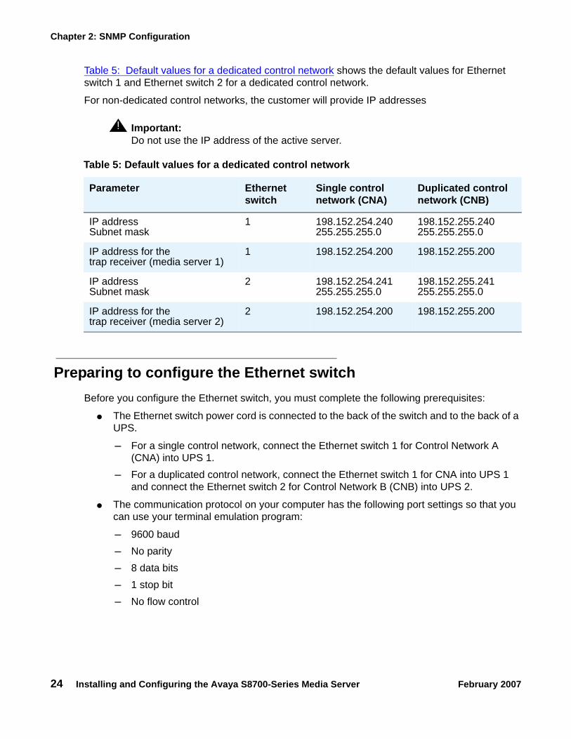
Table 5: Default values for a dedicated control network shows the default values for Ethernet switch 1 and Ethernet switch 2 for a dedicated control network.
For non-dedicated control networks, the customer will provide IP addresses
! Important:Important: Do not use the IP address of the active server.
Preparing to configure the Ethernet switch Before you configure the Ethernet switch, you must complete the following prerequisites:
● The Ethernet switch power cord is connected to the back of the switch and to the back of a UPS.
- For a single control network, connect the Ethernet switch 1 for Control Network A (CNA) into UPS 1.
- For a duplicated control network, connect the Ethernet switch 1 for CNA into UPS 1 and connect the Ethernet switch 2 for Control Network B (CNB) into UPS 2.
● The communication protocol on your computer has the following port settings so that you can use your terminal emulation program:
- 9600 baud- No parity- 8 data bits- 1 stop bit- No flow control
Table 5: Default values for a dedicated control network
Parameter Ethernet switch
Single control network (CNA)
Duplicated control network (CNB)
IP addressSubnet mask
1 198.152.254.240 255.255.255.0
198.152.255.240 255.255.255.0
IP address for the trap receiver (media server 1)
1 198.152.254.200 198.152.255.200
IP addressSubnet mask
2 198.152.254.241 255.255.255.0
198.152.255.241 255.255.255.0
IP address for thetrap receiver (media server 2)
2 198.152.254.200 198.152.255.200
Configuring the SNMP subagent in the Avaya Ethernet switch (if used)
Installing and Configuring the Avaya S8700-Series Media Server February 2007 25
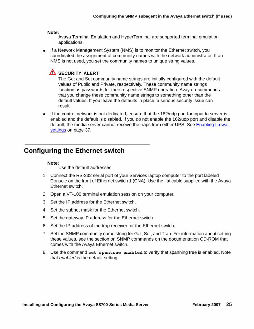
Note:Note: Avaya Terminal Emulation and HyperTerminal are supported terminal emulation
applications.
● If a Network Management System (NMS) is to monitor the Ethernet switch, you coordinated the assignment of community names with the network administrator. If an NMS is not used, you set the community names to unique string values.
! SECURITY ALERT:!
SECURITY ALERT: The Get and Set community name strings are initially configured with the default values of Public and Private, respectively. These community name strings function as passwords for their respective SNMP operation. Avaya recommends that you change these community name strings to something other than the default values. If you leave the defaults in place, a serious security issue can result.
● If the control network is not dedicated, ensure that the 162/udp port for input to server is enabled and the default is disabled. If you do not enable the 162/udp port and disable the default, the media server cannot receive the traps from either UPS. See Enabling firewall settings on page 37.
Configuring the Ethernet switch
Note:Note: Use the default addresses.
1. Connect the RS-232 serial port of your Services laptop computer to the port labeled Console on the front of Ethernet switch 1 (CNA). Use the flat cable supplied with the Avaya Ethernet switch.
2. Open a VT-100 terminal emulation session on your computer.
3. Set the IP address for the Ethernet switch.
4. Set the subnet mask for the Ethernet switch.
5. Set the gateway IP address for the Ethernet switch.
6. Set the IP address of the trap receiver for the Ethernet switch.
7. Set the SNMP community name string for Get, Set, and Trap. For information about setting these values, see the section on SNMP commands on the documentation CD-ROM that comes with the Avaya Ethernet switch.
8. Use the command set spantree enabled to verify that spanning tree is enabled. Note that enabled is the default setting.

Chapter 2: SNMP Configuration
26 Installing and Configuring the Avaya S8700-Series Media Server February 2007
9. Use the command set spantree version rapid-spanning-tree to set the spanning tree version to rapid-spanning-tree. Do not use the default.
Note:Note: This command is available on Avaya Ethernet switches with firmware version 4.0
or later. To use this command, you must update the firmware to this version, if necessary.
For more information on the spanning tree CLI commands, see Installation and Configuration Guide, Avaya C360 and Reference Guide, Avaya C360. These documents are available at the Avaya Support Web site http://www.avaya tha.com/support.
10. If the port networks are IP-PNC, ensure that all appropriate ports on the Ethernet switch are locked to 100 speed and full duplex.
11. When you finish, disconnect your computer from the Ethernet switch.
12. If two Ethernet switches are present for CNA, repeat Steps 1 through 10 for the second switch.
13. If the control network is duplicated, repeat Steps 1 through 11 for each Ethernet switch that remains.

Clearing the ARP cache on the laptop
Installing and Configuring the Avaya S8700-Series Media Server February 2007 27
Chapter 3: Communication Manager installation
A new media server comes with a blank hard disk drive. Use the bootable software distribution CD-ROM to install the Linux operating system and Avaya Communication Manager. On a duplicated system, install the software from the CD onto the hard drive of each media server.
This chapter covers the following tasks:
● Clearing the ARP cache on the laptop on page 27
● Applying power to the media server on page 28
● Accessing the media server on page 28
● Configuring Telnet for Windows 2000 and Windows XP on page 28
● Installing Avaya Communication Manager on page 29
Clearing the ARP cache on the laptop Depending on the operating system of your Services laptop computer, you might need to clear the Address Resolution Protocol (ARP) cache before you enter a new IP address. If you enter an IP address and your computer cannot connect, perform the following procedure to clear the cache.
1. On your computer, click Start > Run to open the Run dialog box.
2. Type command and press Enter to open an MS-DOS command line window.
3. Type arp -d 192.11.13.6 and press Enter to clear the ARP cache in the laptop.
If the ARP cache does not contain the specified IP address, the message The specified entry was not found appears. You can ignore this message.
4. Type exit and press Enter to close the command line window.
Chapter 3: Communication Manager installation
28 Installing and Configuring the Avaya S8700-Series Media Server February 2007
Applying power to the media server Note:
Note: In this procedure, the software CD-ROM must be placed into the CD-ROM drive on the media server immediately after you turn on the power to the media server.
1. Connect the AC power cord to media server 1 and to UPS 1.
2. Press the Power button on the front of the media server. Immediately place the Avaya Communication Manager CD-ROM into the CD-ROM drive on the media server.
Accessing the media server 1. Use a cross-over cable to connect your laptop computer to the Services port on the back
of the media server. The Services port is labeled "2" and is configured as Eth1.
2. Wait at least 3 minutes after you turn on the media server before you start a Telnet session to access the information on the CD-ROM.
Configuring Telnet for Windows 2000 and Windows XP The Microsoft Telnet application might be set to send a carriage return (CR) and a line feed (LF) whenever you press Enter. The Communication Manager installation program sees this as two key presses. If you are running Windows 2000 or Windows XP, you must correct this setting before you copy the Remaster Program to the hard disk drive.
1. Click Start > Run to open the Run dialog box.
2. Type telnet and press Enter to open a Microsoft Telnet session.
3. Type unset crlf and press Enter.4. Type display and press Enter to verify that you see the message Line feed mode -
Causes return key to send CR.
5. Type q and press Enter to exit the telnet session.
Installing Avaya Communication Manager
Installing and Configuring the Avaya S8700-Series Media Server February 2007 29
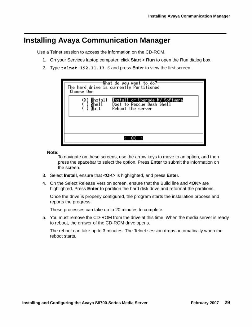
Installing Avaya Communication Manager Use a Telnet session to access the information on the CD-ROM.
1. On your Services laptop computer, click Start > Run to open the Run dialog box.
2. Type telnet 192.11.13.6 and press Enter to view the first screen.
Note:Note: To navigate on these screens, use the arrow keys to move to an option, and then
press the spacebar to select the option. Press Enter to submit the information on the screen.
3. Select Install, ensure that <OK> is highlighted, and press Enter.4. On the Select Release Version screen, ensure that the Build line and <OK> are
highlighted. Press Enter to partition the hard disk drive and reformat the partitions.
Once the drive is properly configured, the program starts the installation process and reports the progress.
These processes can take up to 20 minutes to complete.
5. You must remove the CD-ROM from the drive at this time. When the media server is ready to reboot, the drawer of the CD-ROM drive opens.
The reboot can take up to 3 minutes. The Telnet session drops automatically when the reboot starts.

Chapter 3: Communication Manager installation
30 Installing and Configuring the Avaya S8700-Series Media Server February 2007

Installing and Configuring the Avaya S8700-Series Media Server February 2007 31
Chapter 4: Media server configuration
After you install the Communication Manager software, you must use the Avaya Installation Wizard to configure the media server.
This section covers the following tasks:
● Copying files to the media server on page 32
● Creating a super-user login on page 32
● Running the Avaya Installation Wizard on page 34
● Verifying the media server connection to the customer LAN (if provided) on page 34
● Configuring the modem on page 35
● Configuring memory for an S8720 Media Server on page 35
● Enabling firewall settings on page 37
● Enabling network time servers on page 37
● Disconnecting from the media server on page 39
● Configuring a second media server on page 39
Note:Note: Ensure that you have the completed Electronic Preinstallation Worksheet (EPW)
before you start this process.
Note:Note: Ensure that your networking and Web browser settings are correct. For more
information, see Configuring the network for Windows 2000 and XP on page 84.

Chapter 4: Media server configuration
32 Installing and Configuring the Avaya S8700-Series Media Server February 2007
Opening the Maintenance Web InterfaceYou can use the Maintenance Web Interface to copy license files and authentication files, service packs, and update files from the Services laptop to the media server. For how to open the Maintenance Web Interface, see Finding the IP address of the active media server on page 82.
Copying files to the media server 1. From the Maintenance Web Interface, under Miscellaneous, click Download Files.
2. Select File(s) to download from the machine I’m using to connect to the server.3. Click Browse next to the top field to open the Choose File window on your computer. Find
the files that you need to copy to the media server.
4. Click Download to copy the files to the media server.
The files are automatically copied to the default file location.
Creating a super-user loginNote:
Note: A craft level login can create the super-user login in Release 4.0 or later.
Make sure you have a login name and password that the customer would like for the superuser login. If you are a business partner, you can also repeat this procedure to add the dadmin login.
To create a login:
Note:Note: Make sure the customer can change this login, its password, or its permissions
later.
1. Under Security, select Administrator Accounts.
2. Type the login name in the Enter Login ID or Group Name field.
3. Select Add Login, and click Submit.4. Type susers in the login group field.
5. Type prof18 in the additional groups field. prof18 is the code for the customer superuser.

About the Avaya Installation Wizard
Installing and Configuring the Avaya S8700-Series Media Server February 2007 33
6. Put a check in the allow Linux shell access field.
7. Skip the lock this account and date on which account is disabled fields.
8. For the select type of authentication option, select password.
9. Complete the following fields:
● enter key or password
● re-enter key or password
● force password/key change on first login
Note:Note: Do not lock the account or set the password to be disabled.
10. Leave the defaults in the remaining fields.
11. Click Add.
The system tells the login is added successfully.
About the Avaya Installation Wizard Use the Avaya Installation Wizard to automatically:
● Configure the media server
● Install the license file
Note:Note: To install the license file the server does not have to be connected to the
reference IPSI. However, you have only 30 minutes before the system checks the serial number on the IPSI. To add another 30 minutes, type reset system 1 and press Enter in a SAT session to restart the Communication Manager software.
● Install the Avaya authentication files
● Install software updates
To use the Installation Wizard, you can either:
● Import the data from the completed Electronic Preinstallation Worksheet (EPW). When the Installation Wizard prompts you to import the Preinstallation Worksheet, click Import EPW and browse to the location of the EPW file on your Services laptop computer. The Installation Wizard opens the EPW and uploads the configuration data.
● Type the information manually with the completed EPW as a guide. The Installation Wizard prompts you to enter the configuration data for each step in the Configure Server section.

Chapter 4: Media server configuration
34 Installing and Configuring the Avaya S8700-Series Media Server February 2007
Running the Avaya Installation Wizard1. With the Web browser open, type 192.11.13.6 and press Enter in the browser address
window to display the login page.
2. Log in as craft and use the initial craft password.
3. Click Launch Avaya Installation Wizard.
4. Follow the prompts. For more information use Help on each page.
CAUTION:!
CAUTION: The license settings for the platform and the port network connectivity (PNC) attributes for the S8700-series Media Server can be complex. For more information, see PNC license settings for S8700-series Media Servers on page 9.
Verifying the media server connection to the customer LAN (if provided)
1. From the Maintenance Web Interface, under Diagnostics, click Ping.
2. Select Host Name Or IP Address and type the IP address of a computer on the network.
3. Click Execute Ping.
4. Verify that the ping was successful and indicates that the media server is connected to the customer network.
5. If DNS is administered, type the host name of a computer on the network.
6. Click Execute Ping.
7. Verify that the ping was successful and indicates that DNS is working.
If possible, have a customer representative perform the following test from a computer on the network:
1. Click Start > Run to open the Run dialog box.
2. Type command and click OK to open an MS-DOS command window.
3. Type ping serveripaddress and press Enter, where serveripaddress is the IP address of the media server.
4. Verify that the ping was successful.
5. If DNS is administered, type ping servername and press Enter, where servername is the host name of the media server.
6. Verify that the ping was successful.

Configuring the modem
Installing and Configuring the Avaya S8700-Series Media Server February 2007 35
Configuring the modem 1. From the Maintenance Web Interface, under Server Configuration click Configure Server.2. Click Continue until you get to the Specify how you want to use this wizard page.
3. Select Configure individual services and click Continue.
4. On the menu on the left, click Set Modem Interface.
5. Select Change Modem Setting and click Continue.
6. In the Extra Modem Initialization Commands window, type the initialization commands that are appropriate for your modem and the country of operation. Click Help for help on what to enter.
For example, to change the country code to Japan, type AT%T19,0,10.
7. Click Change.
The system displays a message that indicates that a modem route was added successfully.
Configuring memory for an S8720 Media ServerYou must select the memory configuration to be used for an S8720 Media Server system: either Standard or Extra Large. If Hardware Duplication is turned on, administration for the S8720 in an XL configurations is allowed only if the media servers are equipped with DAL2 duplication memory cards.
Note:Note: If the customer chooses to increase the number of VAL circuit packs or the
number of Logged-In Agents, the customer will need to get a new License File with increased capacities.
Note:Note: If the main servers are configured as S8720 in XL configuration, ESSs and LSPs
also must be configured to be compatible with the main S8720 in XL configuration.
1. From the Maintenance Web Interface, under Server Configuration, click Configure Server.

Chapter 4: Media server configuration
36 Installing and Configuring the Avaya S8700-Series Media Server February 2007
2. Click Continue until you get to the Specify how you want to use this wizard page.
3. Select Configure individual services and click Continue.
4. On the main menu under Configure Individual IP Services, click
● Configure Memory (if a main server)
● Configure ESS (if an ESS server)
5. Select either Standard or Extra Large.
6. Click Change to change values.
7. Click Close Window.
Enabling firewall settings
Installing and Configuring the Avaya S8700-Series Media Server February 2007 37
Enabling firewall settings For the media server to receive SNMP traps from the UPS and the Avaya Ethernet switch, you must enable the snmptrap,162/udp port. The default is disabled.
1. From the Maintenance Web Interface, under Security, click Firewall.2. Scroll down to the snmptrap 162/udp row and select (check) the Input to Server box.
The Output to Server box can be left as is, either checked or clear.
3. Click Submit.
Enabling network time servers
! Important:Important: Avaya strongly recommends that you enable Network Time Protocol (NTP) and
configure at least one network time server. If a network time server is not used the Date/Time settings on the media server must be reset regularly, at least monthly, using the Maintenance Web Interface. The network time strategy is determined by the network administrator.
With NTP, you can specify one, two, or three network time servers to provide the accurate time of day data to the clocks on the media servers. The network time servers, in turn, get their source timing from one of several highly accurate time services that are available on the Internet.
To use a network time server, the NTP service must be enabled. The Avaya Installation Wizard prompts you to enable the NTP service. If you do not use the Installation Wizard, use the Configure Server function on the Maintenance Web Interface to configure the network time servers.
1. From the Maintenance Web Interface, under Server Configuration, click Configure Server.
2. Click Continue on the Review Notices page and the Backup Up Data page.
3. On the "Specify how you want to use this wizard" page, select Configure individual services and then click Continue.
4. In the menu on the left side of the Configure Server page, click Configure Timer Server.5. Enter the NTS information on the Configure Time Server screen and click Change.6. On the main menu, under Security, click Firewall.7. In the "Output from Server" column, select ntp 123/udp.

Chapter 4: Media server configuration
38 Installing and Configuring the Avaya S8700-Series Media Server February 2007
Note:Note: It is not necessary to enable the "Input to Server" ntp service. If this service is
already enabled, you do not need to disable it.
When the Avaya Installation Wizard prompts you for information about the network time servers, enter the DNS name or the IP address for the primary network time server and the secondary and the tertiary time servers if any. If you enter a DNS name instead of an IP address for the network time server, you must specify the IP address of the DNS server. For more information, see About the Avaya Installation Wizard on page 33.
For more information about NTP, see RFC 958.
Configuring the NIC 1. From the Maintenance Web Interface, under Server Configuration, click Configure
Server.2. Click Continue until you get to the "Specify how you want to use this Wizard" page.
3. Select Configure Individual Services and click Continue.
4. On the menu on the left, click Set Identities5. Use the drop-down menus to assign the Ethernet port functions. Click Continue.
6. Complete the following information for Ethernet 2:
● IP address
● Gateway
● Subnet mask
● Speed

Disconnecting from the media server
Installing and Configuring the Avaya S8700-Series Media Server February 2007 39
7. Verify with the network administrator that the LAN hardware supports 802.1q priority tagging. If supported, select VLAN 802.1q priority tagging.
8. Click Change. The system displays the status of the configuration update.
When the update is complete, the system displays the following message:
Successfully configured ethernet interfaces.
Disconnecting from the media server Unplug the cross-over cable from the Services port on the back of the media server.
Configuring a second media server Use the same procedures that you used to configure the first media server. Repeat Clearing the ARP cache on the laptop on page 27 through Disconnecting from the media server on page 39 for the second media server.

Chapter 4: Media server configuration
40 Installing and Configuring the Avaya S8700-Series Media Server February 2007

Installing and Configuring the Avaya S8700-Series Media Server February 2007 41
Chapter 5: IP interface translations
To administer IPSI circuit packs, use a terminal emulation program to issue Communication Manager SAT commands.
For Communication Manager terminal emulation, use a program such as Avaya Native Configuration Manager, Avaya Terminal Emulation, or HyperTerminal.
You also can use Avaya Site Administration to issue SAT commands. To administer some of the features in the latest release of Avaya Communication Manager, you must use the latest version of Avaya Site Administration.
Perform these tasks to administer IPSI circuit packs:
● Inputting initial system translations on page 41● Adding media gateways on page 42● Enabling the IPSI on page 43● Adding the IPSI to the system on page 44● Enabling IPSI duplication (duplicated control network only) on page 45● Setting the alarm activation level on page 45● Saving translations on page 45
Inputting initial system translations 1. Open a SAT session. See Using the SAT command line prompt on page 83.
2. Enter translations:
If the system translations were prepared offsite, enter the translations and reset the media server.
If the translations are not available, enter minimal translations to verify connectivity to the port networks.
3. After you enter the translations, type save translation and press Enter to save the translations to the hard disk drive.
4. Type reset system 4 and press Enter to have the software read the copied translations.

Chapter 5: IP interface translations
42 Installing and Configuring the Avaya S8700-Series Media Server February 2007
Adding media gateways Note:
Note: If system translations have been loaded on the media server, media gateways do not need to be added to administer the IPSI.
1. Type add cabinet n and press Enter, where n is the cabinet number, for each stack of media gateways that is controlled by one TN2312BP IPSI circuit pack.
A cabinet is defined as a group of up to five G650 Media Gateways that are mounted in a rack and TDM-connected.
2. Fill in the carrier location letter and the carrier type for each media gateway in the cabinet.
add cabinet 1 Page 1 of 1CABINET
CABINET DESCRIPTION Cabinet: 1 Cabinet Layout: G650-rack-mount-stack Cabinet Type: expansion-portnetwork
Number of Portnetworks: 1Survivable Remote EPN? n
Location: 1 IP Network Region:1Cabinet Holdover: A-carrier-only
Room: Floor: Building:
CARRIER DESCRIPTION Carrier Carrier Type Number
E not-used PN 09 D not-used PN 09 C not-used PN 09 B G650-port PN 09 A G650-port PN 09

Enabling the IPSI
Installing and Configuring the Avaya S8700-Series Media Server February 2007 43
Enabling the IPSI1. Type change system-parameters ipserver-interface and press Enter. 2. On a duplicated media server, the system displays the following screen. Verify that the
primary control and the secondary control subnetwork addresses are correct.
The control subnetwork addresses typically match the most significant three octets of the IP addresses of the server for the media gateway. The most significant three octets are the first three groups of digits in the IP address. Select the configure server command on the Maintenance Web Interface to see the IP address of the server.
An asterisk (*) to the right of the Control Subnet Address field means that Communication Manager does not have the subnetwork information and the subnetwork address displayed is incorrect.
3. If the information in the Primary Control Subnet Address field, the Secondary Control Subnet Address field, or both fields is incorrect, use the Maintenance Web Interface to change the media server configuration to match the Server IP address in configure server. Under Server Configuration and Upgrades, click Configure Server to change the media server configuration. Then return to this procedure.
4. Set the Switch Identifier field to the switch ID letter. Acceptable switch ID letters are A through J. A is the default setting.
5. Set the IPSI Control of Port Networks field to enabled.
6. Press Enter to save the changes.
change system-parameters ipserver-interface Page 1 of 1
IP SERVER INTERFACE (IPSI) SYSTEM PARAMETERS
SERVER INFORMATION
IPSI Host Name Prefix: birch Primary Control Subnet Address: 198.152.254. 0 * Secondary Control Subnet Address: 198.152.255. 0 *
OPTIONS
Switch Identifier: AIPSI Control of Port Networks: enabled

Chapter 5: IP interface translations
44 Installing and Configuring the Avaya S8700-Series Media Server February 2007
Adding the IPSI to the system Use the IP Server Interface Administration - Port Network SAT screen to add an IPSI. The information on this screen differs, depending on whether the IP addresses of the IPSI are static or assigned automatically through DHCP.
1. Type add ipserver-interface PNnumber and press Enter.2. For the Host field and the DHCP ID fields for the primary IPSI and secondary IPSI, if any:
● For dynamic addressing, the DHCP server sets the Host field and the DHCP ID field. Verify that the fields are populated with default data.
● For static addressing, in the Host field, enter the IP address for the IPSI that is listed in the Location field.
3. Set the IP Control field to y.
add ipserver-interface 4 Page 1 of 1 IP SERVER INTERFACE (IPSI) ADMINISTRATION - PORT NETWORK 4
IP Control? y Socket Encryption? nIgnore Connectivity in Server Arbitration? n Enable QoS? n
Primary IPSI ------------ Location: 9A01 Host: ipsi-A09a DHCP ID: ipsi-A09a
Secondary IPSI -------------- Location: 9B01 Host: ipsi-A09b DHCP ID: ipsi-A09b
add ipserver-interface 8 IP SERVER INTERFACE (IPSI) ADMINISTRATION - PORT NETWORK 8
IP Control? y Socket Encryption? nIgnore Connectivity in Server Arbitration? n Enable QoS? n
Primary IPSI QoS Parameters ------------ -------------- Location: 1A01 Call Control 802.1p: 6 Host: 172.22.22.174 Call Control DiffServ: 46 DHCP ID: ipsi-A01a
Enabling IPSI duplication (duplicated control network only)
Installing and Configuring the Avaya S8700-Series Media Server February 2007 45
4. Verify that all the other fields are populated and submit the form to save the changes.
5. Repeat this procedure for each port network.
Enabling IPSI duplication (duplicated control network only)
Port networks with duplicated IPSIs have both primary (CNA) and secondary (CNB) IPSI circuit packs. If you disable IPSI duplication, all primary IPSI circuit packs must be active.
Use the System-Parameters Duplication SAT screen to enable IPSI duplication.
1. Enter change system-parameters duplication.
2. Enter y in the Enable Operation of IPSI Duplication field.
3. Submit the screen to save the changes.
Setting the alarm activation level 1. At the SAT, type change system-parameters maintenance and press Enter.2. In the CPE Alarm Activation Level field, enter none, warning, minor, or major,
according to the customer request.
3. Submit the screen to save the changes.
4. Repeat this procedure for each IPSI.
Saving translations To save the translations to the hard disk drive, at the SAT, type save translation and press Enter.

Chapter 5: IP interface translations
46 Installing and Configuring the Avaya S8700-Series Media Server February 2007

Installing and Configuring the Avaya S8700-Series Media Server February 2007 47
Chapter 6: IP interface configuration
This chapter covers the following tasks:
● Connecting to the IPSIs on page 47
● IPSI address configuration on page 47
● Programming the IPSI for DHCP addressing on page 53
● Programming the IPSI for static addressing on page 48
● Verifying connectivity to the media server on page 55
● Verifying that the IPSIs are translated on page 56
● Upgrading the IPSI firmware version (if necessary) on page 56
● Enabling control of the IPSIs on page 56
● Verifying the license status on page 57
At a minimum, you must program and connect to the reference TN2312BP IP Server Interface (IPSI) so that the system does not enter No License Mode. Once you connect the IPSIs to the control network, the IPSIs might generate an alarm if the firmware is not the most current. The alarm stops automatically once you upgrade the IPSI firmware.
Connecting to the IPSIs Connect CAT5 cables from the IPSI circuit packs to the dedicated control network or to the customer LAN.
IPSI address configuration The IPSI circuit pack receives an IP address:
● Statically with static IP addressing, if the control network is nondedicated (public) through the customer network.
● Dynamically with dynamic host configuration protocol (DHCP), if the control network is dedicated (private).
Chapter 6: IP interface configuration
48 Installing and Configuring the Avaya S8700-Series Media Server February 2007
Note:Note: To program DHCP addressing, you must complete certain sequences within a
predetermined time-out interval. Avaya recommends that you read the following procedure completely before you start so that you are familiar with these sequences in advance.
Perform one of the following tasks depending on whether you use static or dynamic addressing:
● Programming the IPSI for static addressing on page 48
● Programming the IPSI for DHCP addressing on page 53
Programming the IPSI for static addressing
! Important:Important: If an IPSI is in a port network that is backed up with the Enterprise Survivable
Server (ESS) option you must use static addressing for the ESS to provide service to the port network.

IPSI address configuration
Installing and Configuring the Avaya S8700-Series Media Server February 2007 49
You administer the static IP address for the circuit pack directly through the Ethernet port connection on the faceplate (top port). See Figure 3.
Figure 3: Connecting the laptop directly to the IPSI
Note:Note: Ensure that you have the password before proceeding.
Depending on the operating system on the Services laptop computer, you might need to clear the Address Resolution Protocol (ARP) cache before entering a new IP address. If you enter an IP address and your computer cannot connect, try clearing the cache.
1. On your laptop computer, click Start > Run to open the Run dialog box.
2. Type command and click OK to open a MS-DOS Command Line window.
3. Clear the Address Resolution Protocol (ARP) cache in the laptop.
Figure notes:
1. Services laptop computer2. PCMCIA Network Interface Card (NIC)
3. NIC adapter cable (if necessary)4. CAT5 crossover cable to IPSI
cadlipsi KLC 031502
1
2
CLK
SERVICE
NETWORK
3
4

Chapter 6: IP interface configuration
50 Installing and Configuring the Avaya S8700-Series Media Server February 2007
4. To log into the IPSI, use SSH and the IP address 192.11.13.6.
For information on how to use SSH, see Accessing the command line interface of the server with SSH on page 77.
Note:Note: While connected to the IPSI, type help or ? to obtain online help. Most
commands have two or three letter abbreviations.
5. Type ipsilogin and press Enter.
Note:Note: The craft login used on the IPSI has a different password from the craft login used
on the media servers.
6. Log in as craft.
Prompt = [IPADMIN]:
7. Type show control interface and press Enter and then type show port 1 and press Enter to see the current control interface settings.
8. To set the control interface, type set control interface ipaddr netmask and press Enter, where ipaddr is the customer-provided IP address and netmask is the customer provided subnet mask.
9. Type quit and press Enter to save the changes and exit the IPSI session.
10. Log back in to the IPSI using SSH.
11. Type show control interface and press Enter.The system displays IP address, subnet mask, and default gateway information. Verify that the proper information was entered.
Setting the VLAN and diffserv parameters
Installing and Configuring the Avaya S8700-Series Media Server February 2007 51
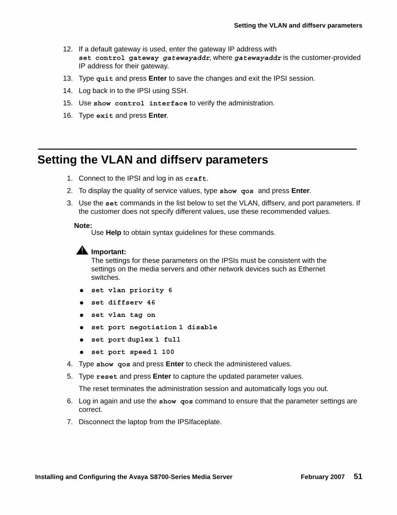
12. If a default gateway is used, enter the gateway IP address withset control gateway gatewayaddr, where gatewayaddr is the customer-provided IP address for their gateway.
13. Type quit and press Enter to save the changes and exit the IPSI session.
14. Log back in to the IPSI using SSH.
15. Use show control interface to verify the administration.
16. Type exit and press Enter.
Setting the VLAN and diffserv parameters 1. Connect to the IPSI and log in as craft.
2. To display the quality of service values, type show qos and press Enter.3. Use the set commands in the list below to set the VLAN, diffserv, and port parameters. If
the customer does not specify different values, use these recommended values.
Note:Note: Use Help to obtain syntax guidelines for these commands.
! Important:Important: The settings for these parameters on the IPSIs must be consistent with the
settings on the media servers and other network devices such as Ethernet switches.
● set vlan priority 6
● set diffserv 46
● set vlan tag on
● set port negotiation 1 disable
● set port duplex 1 full
● set port speed 1 100
4. Type show qos and press Enter to check the administered values.
5. Type reset and press Enter to capture the updated parameter values.
The reset terminates the administration session and automatically logs you out.
6. Log in again and use the show qos command to ensure that the parameter settings are correct.
7. Disconnect the laptop from the IPSIfaceplate.

Chapter 6: IP interface configuration
52 Installing and Configuring the Avaya S8700-Series Media Server February 2007
8. Check the LED on the IPSIfaceplate. Verify that the display shows the letters I and P and a filled-in V at the bottom. (See Figure 4).
Figure 4: IPSI LED display for static address
Note:Note: Clear the ARP cache on the laptop before connecting to another IPSI. If you do
not clear the cache, the laptop appears to stop and does not connect to the next IPSI.
9. Repeat this procedure for each IPSI circuit pack.
Figure notes:
1. IPSI has a static IP address 2. IPSI has connectivity and an IP address
ledl
ip1
KLC
030
502
1
2
CLK
SERVICE
NETWORK

Setting the VLAN and diffserv parameters
Installing and Configuring the Avaya S8700-Series Media Server February 2007 53
Programming the IPSI for DHCP addressing
! Important:Important: If an IPSI is in a port network that is backed up with the Enterprise Survivable
Server (ESS) option you must use static addressing for the ESS to provide service to the port network.
For the TN2312BP IPSI circuit packs to receive IP addresses dynamically, you first must assign the switch ID and cabinet number to each IPSI circuit pack.The switch ID is a single letter, A through J. The cabinet number is a 2-digit number, 01 through 64. For G650 Media Gateways, a cabinet is defined as one or more media gateways connected by a TDM cable. This cabinet configuration is called a G650-rack-mount-stack.
Note:Note: In the following procedure, you must start step 2 within 5 seconds after inserting
the circuit pack.
1. Fully insert the TN2312BP IPSI circuit pack. If necessary, reseat the circuit pack to start the programming sequence.
Note:Note: For the following step, do not use a graphite pencil.
2. Insert a pen, golf tee, or similar object into the recessed push button switch.
CLK
SERV fp
dlle
d3 L
JK 0
2250
2

Chapter 6: IP interface configuration
54 Installing and Configuring the Avaya S8700-Series Media Server February 2007
Note:Note: If you pass the letter or number that you want, you have two options. You can
cycle through all the letters or numbers to get to the one you want. Or, you can reinsert, or reseat, the circuit pack and start again.
Note:Note: If you have only one system, the default switch ID is A. The second system is B
and so on. The switch ID is not the media gateway or carrier letter.
3. While the display characters are flashing, press the button until the switch ID, A through J, shows on the top character of the LED display. When the correct letter shows, stop. The letter flashes a few times, or 5 seconds, then stops. The next character down starts to flash. This is the first digit of the cabinet number.
Note:Note: The number to program is the cabinet number, not the port network number. If
you have more than one IPSI in a cabinet, they all have the same cabinet number.
4. While the first digit of the number is flashing, press the button until the correct tens digit, 0 through 6, for the cabinet number shows on the display. When the correct digit appears, stop. The digit flashes for about 5 seconds, then stops. Then the second digit starts flashing.
5. While the second digit is flashing, press the button until the correct units digit, 0 through 9, for the cabinet number shows on the display. When the correct digit shows, stop. The digit flashes for about 5 seconds, then stops.

Verifying connectivity to the media server
Installing and Configuring the Avaya S8700-Series Media Server February 2007 55
6. All segments of the display go dark for one second. Then, the Switch ID and media gateway stack number shows in the top three characters of the LED display. A "V" is shown in the fourth or bottom character. When the DHCP server assigns an address to the IPSI, the center of the "V" fills in. The filled in "V" looks like the bottom half of a diamond.
For a duplicated control network, repeat these steps for the second IPSI in the cabinet.
Verifying connectivity to the media server 1. Open the Maintenance Web Interface and log in as craft.2. Under Diagnostics, click Ping and select Other server(s), All IPSIs, UPS(s), Ethernet
switches to verify connectivity to these units.
3. Click Execute Ping.
4. Verify that all endpoints respond correctly.
CLK
SERV fp
dlle
d2 L
JK 0
2250
2

Chapter 6: IP interface configuration
56 Installing and Configuring the Avaya S8700-Series Media Server February 2007
Verifying that the IPSIs are translated Note:
Note: You must be on the active media server to use SAT commands.
1. Use SSH to open a SAT session on the media server.
2. Type list ipserver-interface and press Enter.3. Verify that all ISPI circuit packs are translated.
Upgrading the IPSI firmware version (if necessary) You might need to upgrade the firmware on some or all the IPSIs. All IPSIs must have the same firmware load.
1. On the Maintenance Web Interface under IPSI Firmware Upgrades, click IPSI Version.
2. Select Query All and click View.
3. Verify the firmware release for each IPSI.
4. If an upgrade is required, follow the procedures in Firmware Download Procedures at the Download Center on the Avaya Support web site.
Enabling control of the IPSIs 1. Ensure that the IPSIs have the same, current firmware.
2. For duplicated IPSIs, enable IPSI duplication before you enable IPSI control. See Enabling IPSI duplication (duplicated control network only) on page 45. On the SAT, type change system-parameters ipserver-interface and press Enter.
3. Ensure the IPSI Control of Port Networks: field is set to enabled.
4. Submit the screen to save the changes.

Verifying the license status
Installing and Configuring the Avaya S8700-Series Media Server February 2007 57
Verifying the license status On the Maintenance Web Interface, under Security, click License File and verify that the license mode is now normal.

Chapter 6: IP interface configuration
58 Installing and Configuring the Avaya S8700-Series Media Server February 2007

Installing and Configuring the Avaya S8700-Series Media Server February 2007 59
Chapter 7: Postinstallation administration
This section covers the following tasks:
● Verifying translations on page 59
● Setting rules for daylight savings time on page 60
● Setting locations (if necessary) on page 61
● Verifying the date and the time on page 62
● Clearing and resolving alarms on page 62
● Enabling and disabling the Ethernet switch ports on page 63
● Backing up files to the compact flash media on page 65
● Enabling alarms to INADS by way of a modem on page 65
● Enabling alarms to INADS by way of the SNMP module on page 66
● Before leaving the site on page 66
Verifying translations 1. Open a SAT session on the media server.
2. To view all the administered circuit packs in the system, type list configuration all and press Enter.
3. To verify the location of the IPSI circuit packs,type list ipserver-interface and press Enter.
For more information, see your planning documents and check the administration status on the following items:
● list station
● list trunk-group
● list hunt-group

Chapter 7: Postinstallation administration
60 Installing and Configuring the Avaya S8700-Series Media Server February 2007
Setting rules for daylight savings time You set the date, the time, and the time zone through the Maintenance Web Interface on the media server. You must use SAT commands to set the rules for daylight savings time.
Note:Note: The Daylight Savings Rules screen reflects the new dates for Daylight Savings
Time that take effect in 2007.
1. Type change daylight-savings-rules and press Enter.2. In the Change Day, Month, Date, Time, and Increment columns, type the appropriate
start and stop information for each rule. For example, 1:00 in the Increment field means to move the clock forward or back by one hour at the transition point.
You can set up to 15 customized daylight savings time rules. If you have media gateways in several different time zones, you can set up rules for these media gateways on a per-location basis. A daylight savings time rule specifies the exact time when you want to transition to and from daylight savings time. The rule also specifies the increment at which to make the transitions.
Note:Note: The default daylight savings rule is 0, which means that no daylight savings
transition occurs. You can change any rule except rule 0. You cannot delete a daylight savings rule if the rule is in use on either the Locations screen or the Date and Time screens.
3. When you finish, submit the screen to save the changes.
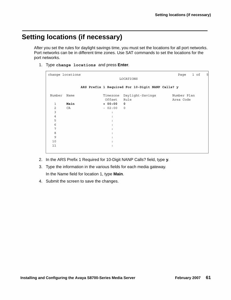
Setting locations (if necessary)
Installing and Configuring the Avaya S8700-Series Media Server February 2007 61
Setting locations (if necessary) After you set the rules for daylight savings time, you must set the locations for all port networks. Port networks can be in different time zones. Use SAT commands to set the locations for the port networks.
1. Type change locations and press Enter.
2. In the ARS Prefix 1 Required for 10-Digit NANP Calls? field, type y.
3. Type the information in the various fields for each media gateway.
In the Name field for location 1, type Main.
4. Submit the screen to save the changes.
change locations Page 1 of 5 LOCATIONS
ARS Prefix 1 Required For 10-Digit NANP Calls? y
Number Name Timezone Daylight-Savings Number Plan Offset Rule Area Code 1 Main + 00:00 0 2 CA - 02:00 0 3 : 4 : 5 : 6 : 7 : 8 : 9 : 10 : 11 :

Chapter 7: Postinstallation administration
62 Installing and Configuring the Avaya S8700-Series Media Server February 2007
Verifying the date and the time Use SAT commands to verify the date and time.
1.Type display time and press Enter.
2. Verify that the date and the time are correct.
3. In the Daylight Savings Rule field, verify that the correct rule number is displayed.
4. If the rule number is correct, you are finished with this task.
5. If the rule number is not correct, go to the Maintenance Web Interface.
6. Under Server, click Server Date/Time. Verify that the date and the time are correct. If not, set the correct date and the correct time.
7. Repeat Steps 1 through 3.
Clearing and resolving alarms 1. On the Maintenance Web Interface, under Alarms, click Current Alarms.
You can resolve alarms on the active media server only.
2. Select the server alarms to clear and click Clear.3. Using SAT commands or other standard troubleshooting procedures, to resolve any major
alarms.
display time Page 1 of 1 DATE AND TIME
DATE
Day of the Week: Friday Month: June Day of the Month: 9 Year: 2006
TIME
Hour: 14 Minute: 19 Second: 36 Type: Standard
Daylight Savings Rule: 0
WARNING: Changing the date or time may impact BCMS, CDR, SCHEDULED

Enabling and disabling the Ethernet switch ports
Installing and Configuring the Avaya S8700-Series Media Server February 2007 63
Enabling and disabling the Ethernet switch ports You might want to disable unused ports on the Avaya Ethernet switch, if used.
1. To select an Ethernet switch to administer, under Security, click Ethernet Switch Ports.
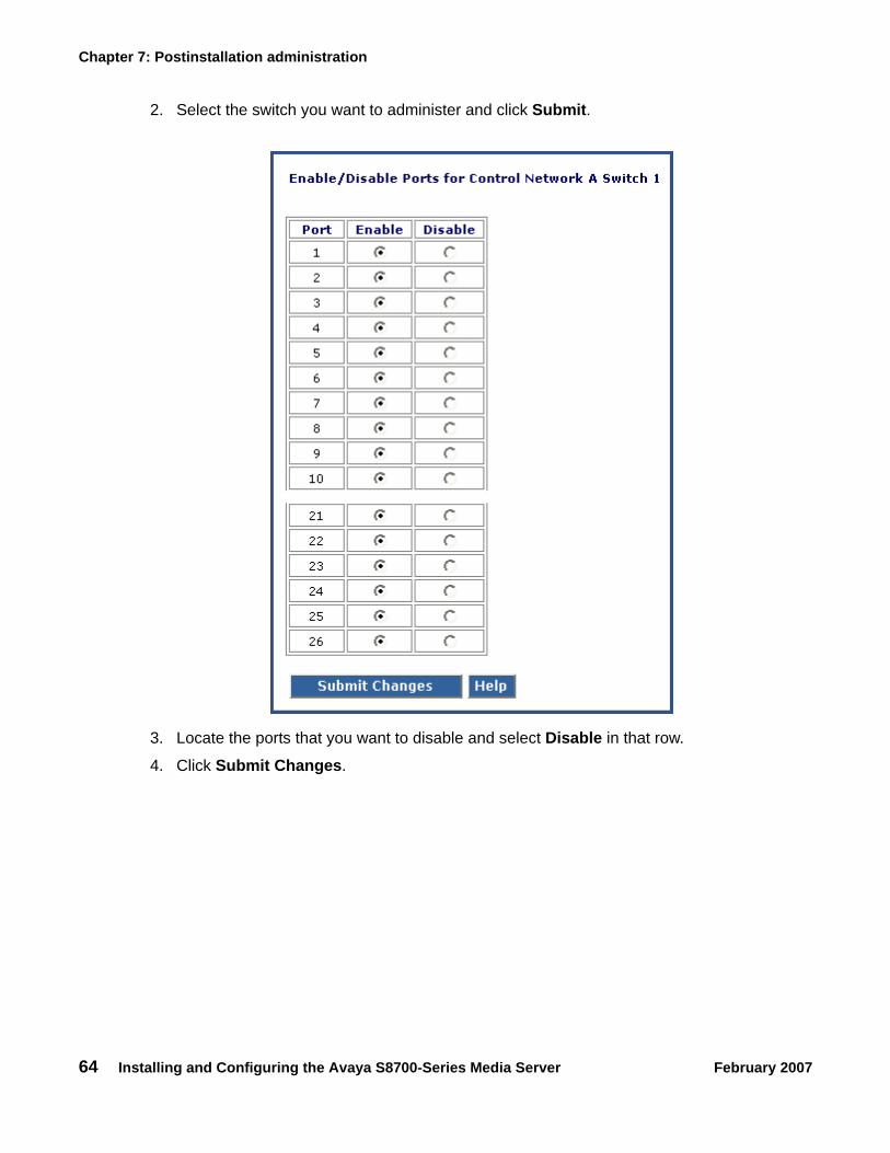
Chapter 7: Postinstallation administration
64 Installing and Configuring the Avaya S8700-Series Media Server February 2007
2. Select the switch you want to administer and click Submit.
3. Locate the ports that you want to disable and select Disable in that row.
4. Click Submit Changes.

Backing up files to the compact flash media
Installing and Configuring the Avaya S8700-Series Media Server February 2007 65
Backing up files to the compact flash media Note:
Note: Avaya requires the use of industrial grade compact flash media. For more information, see Hardware Description and Reference for Avaya Communication Manager (555-245-207).
1. Connect the compact flash drive to one of the USB ports on the back of the media server.
2. Insert the compact flash media into the top right slot of the drive.
3. On the Maintenance Web Interface, under Data Backup/Restore, click Backup Now.
4. Select all applicable data sets.
5. To back up the data onto the compact flash media, select Local PC Card.
To format a new media card, also select Format PC Flash.
Note:Note: You must format the compact flash media before the first use only.
6. Click Start Backup. The system displays a message when the format is completed, which takes approximately 10 seconds.
Note:Note: If you click Start Backup without media in the compact flash drive, you cause a
system error. In this case, repeat the steps beginning with Step 1.
7. To view the status of the backup, click Backup Status.
Enabling alarms to INADS by way of a modem Note:
Note: Enable alarms on both media servers on a duplicated system.
1. Start an SSH session on the media server.
2. Type almenable -d b and press Enter.3. To verify that the alarms are enabled, type almenable and press Enter.
Chapter 7: Postinstallation administration
66 Installing and Configuring the Avaya S8700-Series Media Server February 2007
Enabling alarms to INADS by way of the SNMP moduleNote:
Note: Perform this procedure only if the installation includes a Secure Service Gateway (SSG).
To enable alarms on the media servers:
1. Start an SSH session on the media server.
2. Type almsnmpconf -d ipaddress -c communityname and press Enter, where ipaddress is the trap receiver address for the SSG device and communityname is the community string name that the SSG device requires.
3. Type almsnmpconf and press Enter and verify that the correct information is entered.
4. Type almenable -s y and press Enter.5. Type almenable and press Enter and verify that alarm origination is enabled on the
SNMP module. If used, also verify that alarm origination by way of a modem is still enabled.
6. Log off.
Before leaving the site ● Provide the default LAN security settings to the customer.
● Ensure that the customer knows that remote access to the media server is available only if the following services are enabled on the Maintenance Web Interface Firewall screen:
- SSH must be enabled- https must be enabled to access the Maintenance Web Interface- def-sat must be enabled to access the SAT commands- 162/udp must be enabled to receive SNMP traps from the UPS and the Avaya
Ethernet switch

Installing and Configuring the Avaya S8700-Series Media Server February 2007 67
Chapter 8: Installation verification
This chapter provides the following information about how to verify the media server installation and configuration:
● Testing the IPSI circuit packs
● Testing the license file
● Checking LED status indicators
- Media servers- Avaya Ethernet switches- Uninterruptible power supplies (UPSs)- Circuit packs
Testing the IPSI circuit pack The following steps test the clock and packet interface components within the TN2312BP IPSI circuit pack.
Note:Note: With duplicated media servers, use the active media server.
1. In a SAT command line, type test ipserver-interface UUC and press Enter, where UUC is the cabinet and the carrier in which the circuit pack is located.
2. Verify that the Test Results screen shows PASS in the Results column.
Testing the license file
! Important:Important: Wait at least 30 minutes after you install the Communication Manager license
before you run this test.
Note:Note: With duplicated media servers, use the active media server.
1. On a SAT command line, type test license and press Enter.2. Verify that the Test Results screen shows PASS in the Results column.

Chapter 8: Installation verification
68 Installing and Configuring the Avaya S8700-Series Media Server February 2007
S8710 and S8720 LEDs Figure 5: LEDs on the front panel of the S8710 and the S8720 Media Servers and Figure 6: LEDs on the back panel of the S8710 and the S8720 Media Servers on page 69 show the LEDs on the S8710 and the S8720 Media Servers.
You cannot test the LEDs on the S8710 Media Server.
Figure 5: LEDs on the front panel of the S8710 and the S8720 Media Servers
Figure notes:
1. Internal health2. Power supply3. NIC 1 (Eth0) link/activity
(green)
4. NIC 2 (Eth1) link/activity (green)5. Indicates active when on steady or standby mode when
blinking (blue)6. Power on/standby button/system power
- Amber: power to the chassis is on but the server is off- Green: power is on and the system is running
To turn off the power, press and hold the Power button for several seconds.
Sim
ple
xD
up
lex
ch
ch
2
0
1
1
2
1
10
discCOMPACT
msdsled1 KLC 041304
2
1
1
2
3
4
5
6

Additional media server LED information
Installing and Configuring the Avaya S8700-Series Media Server February 2007 69
Note:Note: The Active/Standby LED, which is labeled as 5 in Figure 5, is on a push button.
When pushed, this button has no effect other than to turn off the LED momentarily. The LED returns to the normal state within a few seconds after the button is pushed.
Figure 6: LEDs on the back panel of the S8710 and the S8720 Media Servers
Additional media server LED information For more information on media server LEDs, see Maintenance Procedures for Avaya Communication Manager, Media Gateways and Servers, 03-300432.
Figure notes:
1. Not used2. Not used3. For hardware duplication mode on
the S8710, DAL1 fault (amber)4. For hardware duplication mode on
the S8710, DAL1 power (green)
5. RJ45 link (green6. RJ45 link (green)7. Indicates active when on steady or standby mode
when blinking (blue)This LED duplicates the Active/Standby LED on the front panel.
8. Power supply (green)
2
3
iLO
VDCI
1
2
3
133 MGz
100 MGz
100 MGz
UID
2 1
DA
L1D
UP
ME
MO
RY
RE
CE
IVE
MO
DE
LIN
CS
YN
C
TR
AN
SM
OD
E
LIN
CA
CT
IVE
msds871c KLC 093004
5 6
2
3
1
2
3
4
7
8

Chapter 8: Installation verification
70 Installing and Configuring the Avaya S8700-Series Media Server February 2007
Avaya C360 Ethernet switch LEDsThe C360 series converged, stackable, Ethernet switches include:
● C363T: 24-port
● C363T-PWR: 24-port power over Ethernet (PoE)
● C364T: 48-port
● C364T-PWR: 48-port PoE
The front panel of the C360-Series switches has:
● One port LED that is associated with each port
● Three system status LEDs
● Seven port function LEDs
The C363T-PWR and the C364T-PWR switches have an additional PoE LED. The port function LEDs are selectable with a set of two left/right buttons. The port LEDs display the status of the selected function for each port.
For more information about the on/off and blinking states of the LEDs, see the documentation for the Ethernet switch.
System and port function LEDs on C360 Avaya Ethernet switches
LED Name Description
System LEDsPWR Power status
SYS System status
ROUT Routing mode
Port Function LEDsLNK Link status
COL Collision status
Tx Transmit to line
Rx Receive from line
FDX Full duplex mode
Hspd High-speed mode
LAG Link aggregation group for trunking
PoE (PWR versions only) Power over Ethernet status
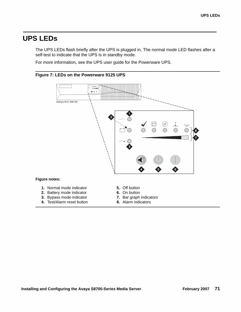
UPS LEDs
Installing and Configuring the Avaya S8700-Series Media Server February 2007 71
UPS LEDs The UPS LEDs flash briefly after the UPS is plugged in. The normal mode LED flashes after a self-test to indicate that the UPS is in standby mode.
For more information, see the UPS user guide for the Powerware UPS.
Figure 7: LEDs on the Powerware 9125 UPS
Figure notes:
1. Normal mode indicator2. Battery mode indicator3. Bypass mode indicator4. Test/Alarm reset button
5. Off button6. On button7. Bar graph indicators8. Alarm indicators
12
3
4 5 6
7
8
ledlups KLC 030102

Chapter 8: Installation verification
72 Installing and Configuring the Avaya S8700-Series Media Server February 2007
TN2312BP IPSI LEDs TN2312BP IP Server Interface (IPSI) circuit pack LEDs include:
● Standard LEDs and connector slots (Figure 8: TN2312BP IPSI circuit pack faceplate on page 73)
● A programmable LED display, which indicates:
- The type of IPSI IP address. For a dynamic address, the display shows media gateway the location of the media gateway. For a static address, the display shows I P. (Figure 9: IPSI LED display for a static IP address on page 74)
- Connectivity

TN2312BP IPSI LEDs
Installing and Configuring the Avaya S8700-Series Media Server February 2007 73
Figure 8: TN2312BP IPSI circuit pack faceplate
Figure notes:
1. Red LED2. Green LED3. Amber LED4. Yellow LED (tone clock status)5. Emergency transfer LED
6. Services RJ45 connector7. Network control RJ45 connector8. Four-character LED display9. Pushbutton switch
10. Slot for the maintenance cable
ckdf
ips2
KLC
091
403
CLK
SERVICE
NETWORK
7000
6064
3
AVA
YA01
DR
0614
2246
TN
2312
AP
IP
SI
3
4
5
8
9
1
2
6
7
10

Chapter 8: Installation verification
74 Installing and Configuring the Avaya S8700-Series Media Server February 2007
Figure 9: IPSI LED display for a static IP address
Figure notes:
1. The IPSI has a static IP address.
2. The IPSI has connectivity and an IP address.
ledl
ip1
KLC
030
502
1
2
CLK
SERVICE
NETWORK

TN2312BP IPSI LEDs
Installing and Configuring the Avaya S8700-Series Media Server February 2007 75
Figure 10: IPSI LED display indicating connectivity status for a DHCP IP address
Connectivity status 1 2 3 4 5
The IPSI is connected to a media server. No Yes Yes Yes Yes
The IPSI has an IP address. No No Yes Yes No
The Services laptop computer is connected to the IPSI services port.
No No No Yes Yes
ledl
ipsi
KLC
030
502
1 2 43 5

Chapter 8: Installation verification
76 Installing and Configuring the Avaya S8700-Series Media Server February 2007

Installing and Configuring the Avaya S8700-Series Media Server February 2007 77
Appendix A: Media server access
Use a personal computer or a Services laptop computer that is equipped with a network interface card (NIC), a terminal emulation program, and a Web browser to access a media server for initial configuration, aftermarket additions, and continuing maintenance.
You can access the media server:
● Directly
● Remotely over the customer network
● Remotely over a modem (for Avaya maintenance access only)
Steps to access a media server include:
● Connecting to the media server directly on page 79
● Connecting to the media server remotely over the network on page 81
● Connecting to the media server remotely over a modem on page 81
● Logins for Avaya technicians and BusinessPartners on page 84
● Configuring the network for Windows 2000 and XP on page 84
Accessing the command line interface of the server with SSH
The procedure in this section shows how to use SSH to log on to the media server from a Services laptop computer. SSH is the recommended method for media server access. To use this procedure with a cable connection from the computer to the Services port, you must configure the computer for the network connection.
To use SSH, a third-party SSH client must be installed on your computer. PuTTY is one such client. You can download PuTTY from http://www.putty.nl/download.html. The following procedure describes, as an example of SSH access, how to log on to the server command line with PuTTY.
Note:Note: A version of PuTTY that is defaulted for SSH server access is available for Avaya
Services personnel only. In this version, some values shown in the procedure below are pre-selected.

Appendix A: Media server access
78 Installing and Configuring the Avaya S8700-Series Media Server February 2007
Note:Note: Many Avaya products support access with SSH. However, Avaya does not
provide support for third-party clients that are used for SSH access. Problems with an SSH client, including PuTTY, are the responsibility of the user or the SSH client vendor.
1. On your computer, click on the PuTTY desktop link or click Start > Programs > PuTTY > PuTTY.
The system displays the PuTTY Configuration window with the Session dialog box open.
2. In the Host Name or IP address field, type 192.11.13.6 if you want to connect to the Services port. For access over the LAN or WAN, type the IP address or the host name of the server.
3. In the Port field, type 22.
4. Under Protocol, select SSH.
5. In the PuTTY menu on the left, click Connection > SSH.
6. In the Preferred SSH protocol version field, select 2.
7. In the Encryption options window, use the up and down arrows to set AES (SSH-2) as the top option and 3DES as the second option.
Note:Note: You can also customize the PuTTY tool with other settings, such as for color. For
documentation on PuTTY, see http://www.putty.nl/docs.html.
8. In the Backspace key area, select Control-H.
This activates the backspace key while you are using the SAT.
9. Click Open.
Note:Note: If you have not connected to this particular server before, SSH prompts you to
accept the server’s host key. If you save this key when prompted, you will not be prompted if you connect again later. If you do not save the key, PuTTY prompts you the next time you connect to this server.
When you connect though the interface on the Services laptop computer, if you save the host key, the host is identified as 192.11.13.6. If you later connect to a different server through the laptop interface, this new host also shows as 192.11.13.6, but it has a different key. You get a prompt in this case because it appears that the host key has changed.
10. If necessary, click Yes to accept the server’s host key.
The system displays the PuTTY window.
11. Log in as craft.

Connecting to the media server directly
Installing and Configuring the Avaya S8700-Series Media Server February 2007 79
Connecting to the media server directly To access the media server directly, use a computer with the following minimum specifications:
● A Windows 2000 or Windows XP operating system
● 32-MB of RAM
● 40-MB of available disk space
● An RS-232 port connector
● A network interface card (NIC) with a 10/100BaseT Ethernet interface
● A 10/100 BaseT Ethernet, category 5 or better, cross-over cable with an RJ45 connector on each end (MDI to MDI-X)
● A CD-ROM drive
1. Plug one end of the CAT5 cable into the Services access port on the back of the media server. For more information, see Services laptop computer connected directly to the S8710 or S8720 Media Server on page 80.
2. Plug the other end of the CAT5 cable into the NIC on your computer. Use a NIC adapter if necessary.
3. Configure your network connection
● IP address: 192.11.13.5
● Subnetwork mask: 255.255.255.252
For specific information, see Configuring the network for Windows 2000 and XP on page 84.
Once you connect, use a terminal emulation program or a Web browser to administer the media server.

Appendix A: Media server access
80 Installing and Configuring the Avaya S8700-Series Media Server February 2007
Figure 11: Services laptop computer connected directly to the S8710 or S8720 Media Server
Figure notes:
1. Services laptop computer2. Network interface card (NIC)
3. NIC adapter cable (if necessary)4. Black CAT5 cross-over cable
2
3
iLO
VDCI
1
2
3
133 MGz
100 MGz
100 MGz
UID
2 1
DA
L1D
UP
ME
MO
RY
RE
CE
IVE
MO
DE
LIN
CS
YN
C
TR
AN
SM
OD
E
LIN
CA
CT
IVE
cadlsrv2 KLC 042804
1
2
3
4
2 1

Connecting to the media server remotely over the network
Installing and Configuring the Avaya S8700-Series Media Server February 2007 81
Connecting to the media server remotely over the network You can use any computer to connect to the media server through a LAN. The security settings on the LAN must allow remote access.
1. Open a Web browser or a terminal emulation application.
2. In the address field, enter the IP address or the DNS host name that is assigned to the media server that you want to access.
On an S8710 or an S8720, enter the address of the active (alias) media server to connect to the active media server.
Connecting to the media server remotely over a modem Note:
Note: Remote access over a modem is for Avaya services support access only and not for routine administration. Because the media server uses the same modem line to report alarms, the server cannot report new alarms while the line is in use.
You can access the media server through an analog modem. The remote connection requires a minimum data speed of 33.5 kilobits per second.
1. Launch the dial-up connection program, which varies depending on your operating system. Generally, you can access the program through the My Computer or the Control Panel folders. For more information, see the Help system of your computer.
2. To open the New Connection wizard, double-click Make New Connection.
3. Within the wizard, depending on your operating system, you may be asked to:
● Assign a name to the connection.
● Select dial-up to the network for the network connection type.
● Select the modem you will be using for the dial-up connection.
● Enter the appropriate telephone number to access the active server. For the customer-supplied telephone numbers, see the completed Electronic Preinstallation Worksheet.
● Under Advanced, select PPP and log on manually. You might have to type a user name and password, depending on whether or not the media server that you are dialing into has a non-null CHAP secret key. If you need a user name and a password, use craft for the user name and ignore the password field.
4. Click the connection name or icon, if created. Wait for connection.
5. When prompted, enter your remote access login name and password.

Appendix A: Media server access
82 Installing and Configuring the Avaya S8700-Series Media Server February 2007
6. When the system displays the Start PPP now message, click Done. When you see the Connection Complete dialog box, your computer is connected to the media server.
7. Open an SSH session using PuTTY or other client.
See Accessing the command line interface of the server with SSH on page 77 for more information.
8. Within the SSH client, type the IP address of the active media server.
Finding the IP address of the active media server To find the active media server IP address on a duplicated system:
1. Go to the task bar at the bottom right of your computer screen.
2. Right-click on the Network Status icon, and select Status, Details.
3. Scroll down until you see the Server IP address. This is the IP address for the media server that you are connected to.
Accessing the Maintenance Web Interface You can administer the media server through the Maintenance Web Interface. Access the Maintenance Web Interface when connected:
● Over the customer network with MS Internet Explorer 5.5 or 6.0.
● Directly to the Services port on the media server. For more information, see Services laptop computer connected directly to the S8710 or S8720 Media Server on page 80.
To access the Maintenance Web Interface, you must first bypass any proxy servers.
1. In Internet Explorer, click Tools > Internet Options.
2. Click the Connection tab.
3. Click LAN Settings in the lower right, then click Advanced.
4. In the Exceptions box after the last entry, type 192.11.13.65. Click OK to close each of the dialog boxes.
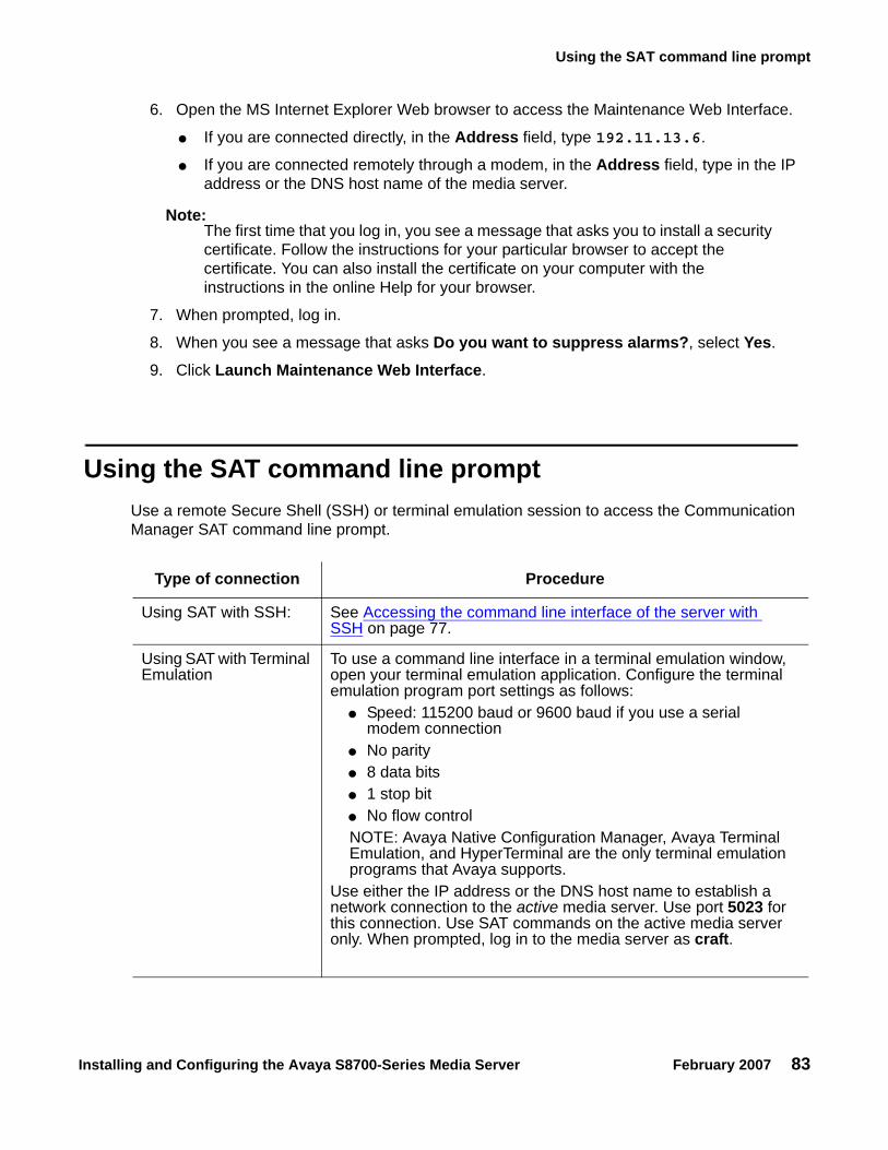
Using the SAT command line prompt
Installing and Configuring the Avaya S8700-Series Media Server February 2007 83
6. Open the MS Internet Explorer Web browser to access the Maintenance Web Interface.
● If you are connected directly, in the Address field, type 192.11.13.6.
● If you are connected remotely through a modem, in the Address field, type in the IP address or the DNS host name of the media server.
Note:Note: The first time that you log in, you see a message that asks you to install a security
certificate. Follow the instructions for your particular browser to accept the certificate. You can also install the certificate on your computer with the instructions in the online Help for your browser.
7. When prompted, log in.
8. When you see a message that asks Do you want to suppress alarms?, select Yes.
9. Click Launch Maintenance Web Interface.
Using the SAT command line prompt Use a remote Secure Shell (SSH) or terminal emulation session to access the Communication Manager SAT command line prompt.
Type of connection Procedure
Using SAT with SSH: See Accessing the command line interface of the server with SSH on page 77.
Using SAT with Terminal Emulation
To use a command line interface in a terminal emulation window, open your terminal emulation application. Configure the terminal emulation program port settings as follows:
● Speed: 115200 baud or 9600 baud if you use a serial modem connection
● No parity● 8 data bits● 1 stop bit● No flow controlNOTE: Avaya Native Configuration Manager, Avaya Terminal Emulation, and HyperTerminal are the only terminal emulation programs that Avaya supports.
Use either the IP address or the DNS host name to establish a network connection to the active media server. Use port 5023 for this connection. Use SAT commands on the active media server only. When prompted, log in to the media server as craft.
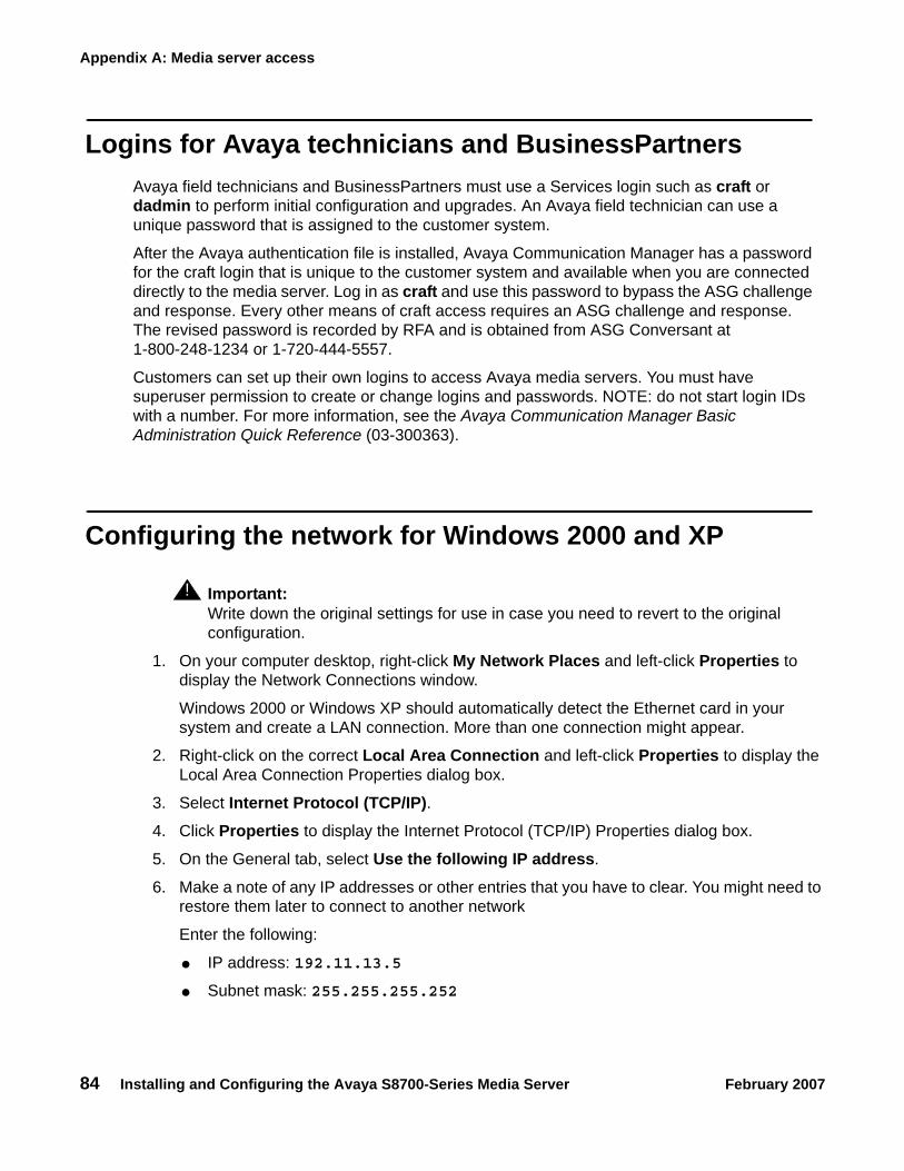
Appendix A: Media server access
84 Installing and Configuring the Avaya S8700-Series Media Server February 2007
Logins for Avaya technicians and BusinessPartners Avaya field technicians and BusinessPartners must use a Services login such as craft or dadmin to perform initial configuration and upgrades. An Avaya field technician can use a unique password that is assigned to the customer system.
After the Avaya authentication file is installed, Avaya Communication Manager has a password for the craft login that is unique to the customer system and available when you are connected directly to the media server. Log in as craft and use this password to bypass the ASG challenge and response. Every other means of craft access requires an ASG challenge and response. The revised password is recorded by RFA and is obtained from ASG Conversant at 1-800-248-1234 or 1-720-444-5557.
Customers can set up their own logins to access Avaya media servers. You must have superuser permission to create or change logins and passwords. NOTE: do not start login IDs with a number. For more information, see the Avaya Communication Manager Basic Administration Quick Reference (03-300363).
Configuring the network for Windows 2000 and XP
! Important:Important: Write down the original settings for use in case you need to revert to the original
configuration.
1. On your computer desktop, right-click My Network Places and left-click Properties to display the Network Connections window.
Windows 2000 or Windows XP should automatically detect the Ethernet card in your system and create a LAN connection. More than one connection might appear.
2. Right-click on the correct Local Area Connection and left-click Properties to display the Local Area Connection Properties dialog box.
3. Select Internet Protocol (TCP/IP).4. Click Properties to display the Internet Protocol (TCP/IP) Properties dialog box.
5. On the General tab, select Use the following IP address.
6. Make a note of any IP addresses or other entries that you have to clear. You might need to restore them later to connect to another network
Enter the following:
● IP address: 192.11.13.5
● Subnet mask: 255.255.255.252

Setting the browser options for Internet Explorer 6.0
Installing and Configuring the Avaya S8700-Series Media Server February 2007 85
7. Select Use the following DNS server addresses. The entries for Preferred DNS server and Alternate DNS server should both be blank.
8. Click Advanced at the bottom of the dialog box to display the Advanced TCP/IP Settings dialog box.
9. Click the DNS tab. Ensure no DNS server is administered. The address field should be blank.
10. Click OK, OK, and Close to close all the windows.
Setting the browser options for Internet Explorer 6.0 A connection session to a media server might time out when connected through a proxy server. To avoid having the media server time out during a session, add the media server host names or IP addresses to the list of host names and IP addresses.
To set browser options for Internet Explorer 6.0:
1. In Internet Explorer 6.0, click Tools > Internet Options.
2. Select the Connection tab.
3. Click on LAN settings, then Advanced.
4. In the Do not use proxy server for addresses beginning with field, type the IP address for each media server you intend to access remotely.
If the IP addresses have the first or first and second octets the same, you can shorten the addresses to xxx.xxx.* (example, 135.9.*).
5. Click OK to close each dialog box.

Appendix A: Media server access
86 Installing and Configuring the Avaya S8700-Series Media Server February 2007

Installing and Configuring the Avaya S8700-Series Media Server February 2007 87
Appendix B: Installation troubleshooting
This section provides some simple strategies to help you troubleshoot an installation of a media server. This section includes:
● Troubleshooting the installation of the media server hardware on page 87
● Troubleshooting the configuration of the media server hardware on page 88
● Troubleshooting the installation of the license file and the Avaya authentication file on page 90
Troubleshooting the installation of the media server hardware
.
Problem Possible solution
No power to the UPS
● Ensure that the UPS is plugged into the outlet.● Ensure that the outlet has power.● For other solutions, see the user guide for the UPS.
No power to the Ethernet switch
● Ensure that the Ethernet switch is plugged into the UPS or the outlet.● Ensure that the UPS or outlet has power.● For other solutions, see the user guide for the Ethernet switch.
No power to the media server
● Ensure that the media server is plugged into the UPS.● Ensure that the UPS has power.● Push the power button on the front of the media server.
The servers are not shadowing
● Make sure you are using a cross-over cable.● Make sure fiber optic cable is plugged in correctly, RX to TX and TX
to RX.
The IPSI LEDs flash
● Ensure that the IPSI is in the correct slot. Use slot 1 for the G650 Media Gateway, slot 2 for the G600 Media Gateway, and the Tone-Clock slot for all others.
● Ping the IPSI from server.● Ping the server from the IPSI.

Appendix B: Installation troubleshooting
88 Installing and Configuring the Avaya S8700-Series Media Server February 2007
Troubleshooting the configuration of the media server hardware
Troubleshooting the configuration of the media server hardware
Problem Possible solution
Cannot log in to the UPS subagent
● Ensure that the SNMP subagent is installed in the UPS.● Ensure that you are connected to the correct Ethernet port.● Ensure that you have the correct login ID and password. For
more information, see the user guide for the SNMP subagent. ● Ensure that the network card on the laptop computer is
configured correctly.
Cannot log in to the Ethernet switch
● Ensure that you are connected to the correct Ethernet port. (On the Ethernet switch, the correct port is labeled Console)
● Ensure that you have the correct login ID and password. See the user guide for the Ethernet switch.
● Ensure that the network card on the Services laptop computer is configured correctly.
Cannot log in to the media server
● Check the link LED. If the LED is off, a cable or hardware problem exists.
● Ensure that you are connected to the Services Ethernet port.● Ensure that you are using a cross-over cable between the
Services laptop computer and the server.● Ensure that the ARP cache is cleared on the Services laptop
computer. In an MS-DOS window, type arp -d 192.11.13.6 and press Enter.
● Ensure that you have connectivity. In an MS-DOS window, type ping 192.11.13.6 and press Enter.
● Ensure that the NIC on the Services laptop computer is configured correctly.
Cannot access the Avaya Installation Wizard
● Ensure that you are plugged into the Services port.● Ensure that you are using the correct IP address, 192.11.13.6 ● Ensure that you are using the correct login and password.● Ensure that the NIC on the laptop is configured correctly.
1 of 2

Troubleshooting the configuration of the media server hardware
Installing and Configuring the Avaya S8700-Series Media Server February 2007 89
Cannot use SAT commands
● Ensure that you are using the correct IP address, 192.11.13.6 and port 5023
● Ensure that you are using the correct login and password.● Make sure you are logged onto the active server.
Cannot ping out to the customer network
● Ensure that in the LAN security settings “output from server” for icmp is enabled.
Cannot ping the media server from the customer network
● Ensure that in the LAN security settings “input to server” for icmp is enabled.
Cannot access the media server remotely
● Ensure that in the LAN security settings “input to server” is checked for SSH (Linux commands), https (Web access), and def-sat (SAT commands access). Change the LAN security settings on the Web interface with a direct connection to the media server.
The LED display on IPSI is flashing
● The IPSI LED is not programmed with the switch and the location (DHCP)
● An IP address is not assigned to the IPSI LED (static IP addressing).
Cannot access the IPSI for static addressing
● Ensure that you are plugged into the Services (top) port on the IPSI.
● Ensure that the ARP cache is cleared on the Services laptop computer. In an MS-DOS command window, type arp -d 192.11.13.6 and press Enter.
No “V” shows on the IPSI LED
● The IPSI is not connected to the Ethernet switch or the network. Connect a cable to the bottom port on the faceplate and to the Ethernet switch or the customer network.
● Make sure port on the Ethernet switch that is assigned to that IPSI is enabled.
The “V” on the IPSI LED is not filled in
● An IP address is not assigned to the IPSI.● The IPSI is not administered.
The system generates an alarm when first connect to IPSI
● The IPSI does not have the current firmware. Upgrade the firmware.
Troubleshooting the configuration of the media server hardware (continued)
Problem Possible solution
2 of 2

Appendix B: Installation troubleshooting
90 Installing and Configuring the Avaya S8700-Series Media Server February 2007
Troubleshooting the installation of the license file andthe Avaya authentication file
Problem Possible solution
Cannot get files from the RFA site ● Provide the correct SAP number.● Provide the serial number for the reference IPSI.
Cannot install the license file ● Ensure that two license files do not exist on the server. If so, delete one of the files.
● The file might be corrupt. Download the file again from the RFA site.
● Use binary mode to upload the file.
The media server is in no-license mode
● The license file does not have an IP address yet. This situation is normal when the license file is first installed because the file cannot see the IPSI.
● After 30 minutes, the license file has not located the reference IPSI. In a SAT session, type reset system 1 and press Enter to reset the 30-minute clock.
Cannot use the administration commands
● The media server might be in no license mode because the 30-minute timer lapsed. In a SAT session, type reset system 1 and press Enter to reset the 30-minute clock.
ASG does not work ● Re-install the Avaya authentication files.
Cannot install the authentification file
● Administer a super-user login on the active server.

Installing and Configuring the Avaya S8700-Series Media Server February 2007 91
Index
Index
Aaccess media server
directly . . . . . . . . . . . . . . . . . . . . . 79remotely over modem . . . . . . . . . . . . . . 81remotely over network . . . . . . . . . . . . . 81
accessing Maintenance Web Interface . . . . . . . 82accessing the media server. . . . . . . . . . . . . 28add
IP interface information . . . . . . . . . . . . . 44media gateways . . . . . . . . . . . . . . . . 42
administerIPSI circuit pack . . . . . . . . . . . . . . . . 47
AIW. See Avaya Installation Wizardalarm activation level
setting . . . . . . . . . . . . . . . . . . . . . 45alarms
enabling to INADS via SNMP . . . . . . . . . . 66setting selected traps . . . . . . . . . . . . . . 22to INADS by way of modem, enabling . . . . . . 65viewing. . . . . . . . . . . . . . . . . . . . . 62
ARP cache, clearing . . . . . . . . . . . . . . . . 27Avaya Installation Wizard, using . . . . . . . . . . 33
Bbacking up files to compact flash . . . . . . . . . . 65
CC363T or C364T Ethernet switch
configuring . . . . . . . . . . . . . . . . . . . 23LEDs . . . . . . . . . . . . . . . . . . . . . 70security alert . . . . . . . . . . . . . . . . . . 23
clearing ARP cache . . . . . . . . . . . . . . . . 27collocated servers, connecting to . . . . . . . . . . 15command line interface. . . . . . . . . . . . . . . 83Communication Manager
installing software. . . . . . . . . . . . . . . . 27compact flash, backing up to . . . . . . . . . . . . 65configure
Avaya C363T or C364T Ethernet switch . . . . . 23media server . . . . . . . . . . . . . . . . .31, 41media server 2 . . . . . . . . . . . . . . . . . 39modem. . . . . . . . . . . . . . . . . . . . . 35network interface card (NIC). . . . . . . . . . . 38UPS . . . . . . . . . . . . . . . . . . . . . . 19
connect to customer network . . . . . . . . . . . . 12connection to LAN, verifying. . . . . . . . . . . . . 34copy files to media server . . . . . . . . . . . . . . 32customer network, connecting to . . . . . . . . . . 12
Ddate and time, verifying . . . . . . . . . . . . . . . 62daylight savings rules
location . . . . . . . . . . . . . . . . . . . . . 61setting . . . . . . . . . . . . . . . . . . . . . 60
DHCP IP addressingIPSI circuit pack . . . . . . . . . . . . . . . . . 47using . . . . . . . . . . . . . . . . . . . . . . 53
diffserv parameters, setting . . . . . . . . . . . . . 51direct access to media server . . . . . . . . . . . . 79disable unused Ethernet switch ports . . . . . . . . 63disconnecting from media server . . . . . . . . . . 39duplicated IPSIs, enabling. . . . . . . . . . . . . . 45
Eenable Ethernet switch ports . . . . . . . . . . . . 63Ethernet switch
configuring . . . . . . . . . . . . . . . . . . . 25default IP addresses. . . . . . . . . . . . . . . 23disabling unused ports . . . . . . . . . . . . . . 63preparing to configure . . . . . . . . . . . . . . 24
Ffaceplate
TN2312BP circuit pack . . . . . . . . . . . . . 72firewall settings . . . . . . . . . . . . . . . . . . . 37
IINADS
enabling alarms to by way of modem . . . . . . . 65inputting translations . . . . . . . . . . . . . . . . 41installation
troubleshooting . . . . . . . . . . . . . . . . . 87using the Wizard . . . . . . . . . . . . . . . . 33
installingCommunication Manager software . . . . . . . . 29translation file . . . . . . . . . . . . . . . . . . 45

92 Installing and Configuring the Avaya S8700-Series Media Server February 2007
Index
IP addressfinding for the active media server . . . . . . . . 82set static . . . . . . . . . . . . . . . . . . . . 48use DHCP . . . . . . . . . . . . . . . . . . . 53
IP address, set static . . . . . . . . . . . . . . . . 48IP interface
enabling control . . . . . . . . . . . . . . . . 56upgrading firmware version . . . . . . . . . . . 56verify translations . . . . . . . . . . . . . . . . 56
IP interface informationadding to translations . . . . . . . . . . . . . . 44
IPSIconnecting to . . . . . . . . . . . . . . . . . . 47enabling duplication. . . . . . . . . . . . . . . 45LEDs . . . . . . . . . . . . . . . . . . . . . 72program switch ID and cabinet. . . . . . . . . . 47
LLED
additional information . . . . . . . . . . . . . . 69LEDs
Avaya Ethernet switches . . . . . . . . . . . . 70IPSI . . . . . . . . . . . . . . . . . . . . . . 72S8700-series Media Server . . . . . . . . . . . 68UPS . . . . . . . . . . . . . . . . . . . . . . 71
license file, testing . . . . . . . . . . . . . . . . . 67license, verifying status. . . . . . . . . . . . . . . 57location
setting for media gateways . . . . . . . . . . . 61login, super-user . . . . . . . . . . . . . . . . . . 32
MMaintenance Web Interface, accessing . . . . . . . 82media gateways, adding . . . . . . . . . . . . . . 42media server
accessing . . . . . . . . . . . . . . . . . . . 28applying power . . . . . . . . . . . . . . . . . 28configuring . . . . . . . . . . . . . . . . . .31, 41copying files to . . . . . . . . . . . . . . . . . 32disconnecting from . . . . . . . . . . . . . . . 39LED, additional information . . . . . . . . . . . 69LEDs . . . . . . . . . . . . . . . . . . . . . 68verify connectivity. . . . . . . . . . . . . . . . 55verifying LAN connection . . . . . . . . . . . . 34
media server 2configuring . . . . . . . . . . . . . . . . . . . 39
modemaccess to media server . . . . . . . . . . . . . 81configuring . . . . . . . . . . . . . . . . . . . 35connect to media server. . . . . . . . . . . . . 15
modem options, setting. . . . . . . . . . . . . . . 16modem, enabling alarms to INADS . . . . . . . . . 65
Nnetwork interface card (NIC)
configuring . . . . . . . . . . . . . . . . . . . 38network time server (NTP), enabling . . . . . . . . . 37
PPNC license settings for S8700 . . . . . . . . . . . . 9post installation tasks . . . . . . . . . . . . . . . . 66power
applying to media server . . . . . . . . . . . . . 28pre-installation tasks at the installation site . . . . . . . 9Processor Ethernet . . . . . . . . . . . . . . . . . 16PuTTY, SSH client . . . . . . . . . . . . . . . . . 77
Rremote access to media server
over modem . . . . . . . . . . . . . . . . . . 81over network . . . . . . . . . . . . . . . . . . 81
SS8700
active medial server, finding the IP address . . . . 82port connections. . . . . . . . . . . . . . . . . 12
S8700-series Media ServerLEDs . . . . . . . . . . . . . . . . . . . . . . 68PNC license settings . . . . . . . . . . . . . . . 9
saving translations . . . . . . . . . . . . . . . 41, 45separated servers, connecting to . . . . . . . . . . 15set
alarm activation level . . . . . . . . . . . . . . 45daylight savings rules . . . . . . . . . . . . . . 60selected traps (alarming). . . . . . . . . . . . . 22static IP address . . . . . . . . . . . . . . . . 48
set static IP address . . . . . . . . . . . . . . . . 48SNMP
preparing to configure . . . . . . . . . . . . . . 21SNMP modules
administering . . . . . . . . . . . . . . . . . . 22software, installing Communication Manager . . . . . 29spanning tree
enabling . . . . . . . . . . . . . . . . . . . . 25setting version . . . . . . . . . . . . . . . . . 25
SSHabout . . . . . . . . . . . . . . . . . . . . . . 17access with . . . . . . . . . . . . . . . . . . . 77
static IP addressingIPSI circuit pack . . . . . . . . . . . . . . . . . 47setting . . . . . . . . . . . . . . . . . . . . . 48
static IP addressing, setting . . . . . . . . . . . . . 48super-user login . . . . . . . . . . . . . . . . . . 32

Installing and Configuring the Avaya S8700-Series Media Server February 2007 93
Index
TTelnet
configuring for Win2000/XP . . . . . . . . . . . 28terminal emulation . . . . . . . . . . . . . . . . . 83testing
license file . . . . . . . . . . . . . . . . . . . 67media server installation . . . . . . . . . . . . 67TN2312BP . . . . . . . . . . . . . . . . . . . 67
TN2312BPfaceplate . . . . . . . . . . . . . . . . . . . . 72LEDs . . . . . . . . . . . . . . . . . . . . . 72program switch ID and cabinet. . . . . . . . . . 47
TN2312BP, testing . . . . . . . . . . . . . . . . . 67translation file
installing . . . . . . . . . . . . . . . . . . . . 45translations
inputting . . . . . . . . . . . . . . . . . . . . 41IP interface . . . . . . . . . . . . . . . . . . . 41saving . . . . . . . . . . . . . . . . . . . .41, 45verifying . . . . . . . . . . . . . . . . . . . . 59
troubleshooting, media server installation . . . . . . 87
Uupgrading
IP interface firmware version . . . . . . . . . . 56UPS
default IP addresses for S8700 . . . . . . . . . 20LEDs . . . . . . . . . . . . . . . . . . . . . 71security alert . . . . . . . . . . . . . . . . . . 19SNMP module . . . . . . . . . . . . . . . . . 19
UPS, configuring. . . . . . . . . . . . . . . . . . 19using DHCP IP address . . . . . . . . . . . . . . 53using this documentation . . . . . . . . . . . . . . . 8
Vverify
connectivity to media servers. . . . . . . . . . . 55date and time . . . . . . . . . . . . . . . . . . 62IP interface translated . . . . . . . . . . . . . . 56license status . . . . . . . . . . . . . . . . . . 57media server connection to LAN . . . . . . . . . 34translations . . . . . . . . . . . . . . . . . . . 59
view alarms . . . . . . . . . . . . . . . . . . . . 62VLAN parameters, setting . . . . . . . . . . . . . . 51
WWizard, installation . . . . . . . . . . . . . . . . . 33

94 Installing and Configuring the Avaya S8700-Series Media Server February 2007
Index


