INSTALLING METAL GUTTER SYSTEMS INSTRUCCIONES EN ESPAÑOL EN EL REVERSO TOOLS REQUIRED Eye protection, pencil, tape measure, string, level, hack saw, drill, screwdriver, hammer, pliers, ladder, tin snips and gloves. PLANNING - Measure Roof Line and Locate Downspouts Use chart to fill in quantity of each item needed to complete your job. (Note: Stores may not stock every item listed below) 40' 20' 20' 20' 40' Downspouts 10' EXAMPLE: # Description Quantity A Gutter - 10 ft. B Downspout - 10 ft. (2x3 or 3x4) C Inside Mitre D Outside Mitre E Right End Cap F Left End Cap G Seamer - 2/pack Easiest, best way to connect gutters H Slip Joint Connector For ease of instal- lation, gently pry open flanges I Hidden Hanger with Screw J Fascia Bracket or Snap Lok Fascia Bracket K Screw or Spike & Ferrule L Hidden Hanger M Hidden Hanger with Roof Strap N End Drop O Front “A” Elbow (2x3 or 3x4) P Side “B” Elbow (2x3 or 3x4) Q Downspout Band Metal or Plastic R SeamerMate ® S Downspout Extension GUTTER MATERIAL SELECTION GUIDE A B C D E F G H I J O P Q R S H R F TTER MATE IDE K L M Gutter Cover Drip Edge Hinged Gutter Guard INSTALLING HANGERS: 3 Use one hanger every 24 in. or every 18 in. for heavy ice & snowload areas. (Fig. 3.1) Fascia Bracket or Snap Lok Bracket Fascia Bracket: 4 per pack, includes hanging nails. Nail along guide string every 24 in. Snap Lok Fascia Bracket: 4 per pack, Nails or screws required. (Fig. 3.2) Hidden Hanger with Screw Power drive ¼ in. hex head screw into fascia board. (Fig. 3.3) Hidden Hanger or Hidden Hanger with Roof Strap Hidden Hanger: Requires nails or screws. Hidden Hanger with Roof Strap: Only use when no fascia board exists. (Fig. 3.4) Screw or Spike and Ferrule Insert ferrule into gutter and fasten screw or spike through gutter, ferrule and fascia board. (Fig. 3.5) Fig. 3.1 Fig. 3.2 Fig. 3.3 Fig. 3.4 Fig. 3.5 (800) 347-2586 www.amerimax.com OR OR OR OR OR # Description Quantity Wide Flange Outlet Metal or Plastic Strainer Hinged Gutter Guard Gutter Guard and Cover 3 ft. & 4 ft. Drip Edge - 10 ft. Splashblock Dripper Flipper FLEX-A-SPOUT ® - Extends to 55 in. Sheet Metal Screws - 8 pack OR OR OR N Flex-A-Spout ® Dripper Flipper MEASURE: 1 REMOVE old gutters and inspect fascia board. REPLACE IF NEEDED. Tack a string to fascia board and level (A). Lower string approximately ¼ in. for every 10 ft. of gutter and retack string. This is sloped toward downspout. If your house has drip edge, slip gutter under drip edge. (Fig. 1.1) Fig. 1.1 ATTACHING MITRES: 4 For a corner, use a mitre attached to gutter with seamers or slip joints. Apply SeamerMate ® to inside mitre joint and all connecting points as illustrated. (Fig. 4.1) Fig. 4.1 ASSEMBLE GUTTER: 2 5 inch Gutter: Begin at end of gutter run, opposite downspout end. Apply SeamerMate™ to end cap. Attach to end of gutter. Join gutter lengths using Seamers - (directions printed on bag) or Slip Joint Connectors (for ease of installation, gently pry open flanges) (Fig. 2.1a) 6 inch Gutter: Gutters connect by cutting 3 in. off top lip and sliding together. (Fig. 2.1b) Fig. 2.1b Fig. 2.1a ® B O P Q S Each downspout and elbow has one end crimped. Parts are joined by fitting the larger end of one over the smaller end of the other, forcing them together tightly. Downspouts should fit snug against the wall. Use sheet metal screws to secure downspouts and elbows. Attach a front or side elbow at the downspout’s bottom to direct water away from the foundation. (Fig. 5.2) Fig. 5.3 Fig. 5.4 ATTACHING DOWNSPOUTS: To connect the gutter to the downspout use either an outlet or an end with drop. For the end with drop, connect to the gutter with a Seamer or slip joint connector. Apply Seamermate™ to end with drop and joint as instructed. If at the end of a run, seal with SeamerMate™ and an end cap. To use an outlet, first make a hole in the gutter for the outlet. Trace the opening of the outlet on the outside of the gutter, drill a hole and cut with tin snips (Fig. 5.1). 5 Use a Downspout Extension, Splashblock, Dripper Flipper, or Flex-A-Spout ® to get water further away from the foundation. (Fig. 5.4) Fasten downspouts against wall with 2 bands per 10 ft. section using nails or screws. (Fig. 5.3) NOTE: • 2" x 3" downspouts drain 186 gallons per minute • 3" x 4" downspouts drain 434 gallons per minute Increasing the size of downspouts or number of downspouts is recommended for wide roof areas, heavy downpour areas, and for gutter systems that overflow. INSTALLING DRIP EDGES: Help direct roof run-off into gutters. To install, lift shingles and insert drip edge under shingles. Push back until drip edge projects approx. ½ in. beyond fascia. Nail under shingles every 5 ft. (Fig. 6.1) 6 Drip Edge Fig. 6.1 N Wide Flange Outlet - Metal Outlet - Plastic Strainer Q Splashblock Sheet Metal Screws O M s M Metal s s Fig. 5.1 Fig. 5.2
Transcript
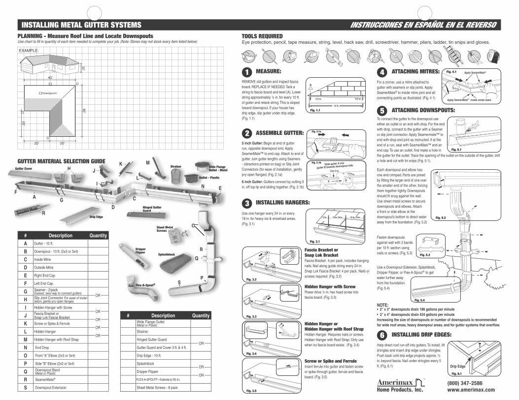
INSTALLING METAL GUTTER SYSTEMS INSTRUCCIONES EN ESPAÑOL EN EL REVERSOTOOLS REQUIREDEye protection, pencil, tape measure, string, level, hack saw, drill, screwdriver, hammer, pliers, ladder, tin snips and gloves.
PLANNING - Measure Roof Line and Locate DownspoutsUse chart to fi ll in quantity of each item needed to complete your job. (Note: Stores may not stock every item listed below)
40'
20'
20'20'
40'
Downspouts
10'
EXAMPLE:
# Description Quantity
A Gutter - 10 ft.
B Downspout - 10 ft. (2x3 or 3x4)
C Inside Mitre
D Outside Mitre
E Right End Cap
F Left End Cap
G Seamer - 2/packEasiest, best way to connect gutters
H Slip Joint Connector For ease of instal-lation, gently pry open fl anges
I Hidden Hanger with Screw
J Fascia Bracket or Snap Lok Fascia Bracket
K Screw or Spike & Ferrule
L Hidden Hanger
M Hidden Hanger with Roof Strap
N End Drop
O Front “A” Elbow (2x3 or 3x4)
P Side “B” Elbow (2x3 or 3x4)
Q Downspout BandMetal or Plastic
R SeamerMate®
S Downspout Extension
GUTTER MATERIAL SELECTION GUIDE
A
B
C
D
EF
G
H
I
J
O
P
Q
R
S
H
R
F
TTER MATE IDE K
L
MGutter Cover
Drip Edge
Hinged Gutter Guard
INSTALLING HANGERS:3Use one hanger every 24 in. or every 18 in. for heavy ice & snowload areas. (Fig. 3.1)
Fascia Bracket orSnap Lok BracketFascia Bracket: 4 per pack, includes hanging nails. Nail along guide string every 24 in. Snap Lok Fascia Bracket: 4 per pack, Nails or screws required. (Fig. 3.2)
Hidden Hanger with ScrewPower drive ¼ in. hex head screw into fascia board. (Fig. 3.3)
Hidden Hanger or Hidden Hanger with Roof Strap Hidden Hanger: Requires nails or screws.Hidden Hanger with Roof Strap: Only use when no fascia board exists. (Fig. 3.4)
Screw or Spike and Ferrule Insert ferrule into gutter and fasten screw or spike through gutter, ferrule and fascia board. (Fig. 3.5)
Fig. 3.1
Fig. 3.2
Fig. 3.3
Fig. 3.4
Fig. 3.5
(800) 347-2586www.amerimax.com
OR
OR
OR
OR
OR
# Description QuantityWide Flange OutletMetal or Plastic
Strainer
Hinged Gutter Guard
Gutter Guard and Cover 3 ft. & 4 ft.
Drip Edge - 10 ft.
Splashblock
Dripper Flipper
FLEX-A-SPOUT® - Extends to 55 in.
Sheet Metal Screws - 8 pack
OR
OR
OR
N
Flex-A-Spout®
Dripper Flipper
MEASURE:1REMOVE old gutters and inspect fascia board. REPLACE IF NEEDED. Tack a string to fascia board and level (A). Lower string approximately ¼ in. for every 10 ft. of gutter and retack string. This is sloped toward downspout. If your house has drip edge, slip gutter under drip edge. (Fig. 1.1)
Fig. 1.1
ATTACHING MITRES:4For a corner, use a mitre attached to gutter with seamers or slip joints. Apply SeamerMate® to inside mitre joint and all connecting points as illustrated. (Fig. 4.1)
Fig. 4.1
ASSEMBLE GUTTER:25 inch Gutter: Begin at end of gutter run, opposite downspout end. Apply SeamerMate™ to end cap. Attach to end of gutter. Join gutter lengths using Seamers - (directions printed on bag) or Slip Joint Connectors (for ease of installation, gently pry open fl anges) (Fig. 2.1a)
6 inch Gutter: Gutters connect by cutting 3 in. off top lip and sliding together. (Fig. 2.1b)
Fig. 2.1b
Fig. 2.1a
®
B
O
P
Q
S
Each downspout and elbow has one end crimped. Parts are joined by fi tting the larger end of one over the smaller end of the other, forcing them together tightly. Downspouts should fi t snug against the wall. Use sheet metal screws to secure downspouts and elbows. Attach a front or side elbow at the downspout’s bottom to direct water away from the foundation. (Fig. 5.2)
Fig. 5.3
Fig. 5.4
ATTACHING DOWNSPOUTS:To connect the gutter to the downspout use either an outlet or an end with drop. For the end with drop, connect to the gutter with a Seamer or slip joint connector. Apply Seamermate™ to end with drop and joint as instructed. If at the end of a run, seal with SeamerMate™ and an end cap. To use an outlet, fi rst make a hole in the gutter for the outlet. Trace the opening of the outlet on the outside of the gutter, drill a hole and cut with tin snips (Fig. 5.1).
5
Use a Downspout Extension, Splashblock, Dripper Flipper, or Flex-A-Spout ® to get water further away from the foundation.(Fig. 5.4)
Fasten downspouts against wall with 2 bands per 10 ft. section using nails or screws. (Fig. 5.3)
NOTE:• 2" x 3" downspouts drain 186 gallons per minute• 3" x 4" downspouts drain 434 gallons per minuteIncreasing the size of downspouts or number of downspouts is recommended for wide roof areas, heavy downpour areas, and for gutter systems that overfl ow.
INSTALLING DRIP EDGES:
Help direct roof run-off into gutters. To install, lift shingles and insert drip edge under shingles. Push back until drip edge projects approx. ½ in. beyond fascia. Nail under shingles every 5 ft. (Fig. 6.1)
6
Drip Edge
Fig. 6.1
N
Wide Flange Outlet - Metal
Outlet - Plastic
Strainer
QSplashblock
Sheet Metal Screws
OMsMMetalss
Fig. 5.1
Fig. 5.2
CÓMO INSTALAR CANALES DE DESAGÛE DE METAL OVER FOR INSTRUCTIONS IN ENGLISHHERRAMIENTAS:Protección ocular, lápiz, cinta métrica, cuerda, nivel, sierra del corte, taladro, destornillador, martillo, alicates, escalera, tijeras para hojalata y guantes.
PLANEAMIENTO - Medición De La Línea Del borde del techo Y Ubicación De Los Conductos De BajadaUse la tabla para Ilenar la cantidad de artículos que necesita para completar su trabajo. (Nota: Puede que las tiendas no tenga todos los artículos enumerados abajo)
GUÍA DE LA SELECCIÓN DE LOS MATERIALES DEL CANAL:
A
B
C
D
EF
G
H
I
J
O
P
Q
S
H
F
A SE ES DEL CK
L
MCubierta del canal
Protector de canaleta ranurado
R
G
R
CÓMO INSTALAR LOS COLGADORES:3Utilice un colgador cada 61 cm (24 po) o cada 46 cm (18 po) en las áreas que reciben mucha nieve o mucho hielo. (Fig. 3.1)
Soporte para el acabado frontal del techo o soporte a resorteSoporte: 4 por paquete, incluye clavos. Clave a lo largo de la cuerda cada 60 cm. Soporte a resorte: 4 por paquete. Requiere clavos o tornillos. (Fig. 3.2)
Colgador invisible con tornilloColoque un tornillo de cabeza hexagonal de 6 mm (¼ po) en el acabado frontol del techo. (Fig. 3.3)
Colgador invisible o Colgador invisible con abrazadera de fi jaciónColgador invisible: Se requiere clavos o tornillos. Colgador invisible con abrazadera de fi jación: Utilice solamente si el techo no tiene acabado frontal. (Fig. 3.4)
Tornillo o Clavo y VarillaInserte la varilla en la canaleta y ajuste con un tornillo o clavo a través de la canaleta, varilla y el acabado frontal del techo. (Fig. 3.5)
Fig. 3.1
Fig. 3.2
Fig. 3.3
Fig. 3.4
Fig. 3.5
(800) 347-2586www.amerimax.com
# Descripción Cantidad
A Canaleta 3m (10 pies)
BConducto de bajada 3m (10 pies) 5.08cm x 7.62cm ó 7.62cm x 10.16cm (2x3 ó 3x4)
C Inglete interior
D Inglete exterior
E Casquete derecho
F Casquete izquierdo
GJunta - 2 por paqueteLa mejor forma de conectar canaletas fácilmente
HConector de junta corredizaPara facilitar la instalación, abra la pestaña con cuidado
I Colgador invisible con tornillo
JSoporte para el acabado frontal del techo oSoporte a resorte para el acabado
K Tornillo o Clavo y Varilla
L Colgador invisible
M Colgador invisible con abrazadera de fi jación
N Colector de agua
O Codo frontal “A” 5.08cm x 7.62cm ó 7.62cm x 10.16cm (2x3 ó 3x4)
P Codo lateral “B” 5.08cm x 7.62cm ó 7.62cm x 10.16cm (2x3 ó 3x4)
Q Abrazadera del conducto de bajadaMetal o plástico
R Pegamento SeamerMate®
S Extensión del conducto de bajada
ó
ó
ó
ó
ó
# Descripción CantidadTubo de salida de pestaña anchaMetal o plástico
Filtro
Protector de canaleta ranurado
Protector y cubierta de canaleta de 91 cm y 120 cm (3 pies y 4 pies)
Borde de desagüe - 3m (10 pies)
Protector de salpicaduras
Basculador de goteo
Conexión FLEX-A-SPOUT® - Se extiende hasta 1.4 m (55 po)
Tornillos de metal - 8 por paquete
ó
ó
ó
N
:
Flex-A-Spout®
Basculador de goteo
CÓMO MEDIR:1REMUEVA las canaletas usadas e inspeccione el acabado frontal del techo. REMPLACE SI FUERA NECESARIO. Clave una cuerda en el acabado y nivele (A).Baje la cuerda aproximadamente 6 mm(¼ po) por cada 3 m (10 pies) de canaleta y vuelva a clavar la cuerda. Ésta se inclina hacia el conducto de bajada. Si el techo tiene bordes de desagüe, deslice la canaleta debajo del borde. (Fig. 1.1)
Fig. 1.1
CÓMO UNIR LOS INGLETES:4Para una esquina, utilice un inglete unido a la canaleta por medio de una junta o un conector de juntas corredizas. Aplique SeamerMate® a la junta del inglete interior y a todos los puntos de conexión, tal como se ilustra en la. (Fig. 4.1)
Fig. 4.1
CÓMO ENSAMBLAR LA CANALETA:2Canaleta de 12.7 cm (5 po): Empiece por el
extremo de la canaleta, opuesto al extremo del
conducto de bajada. Aplique SeamerMate® al
casquete. Fije al extremo de la canaleta. Una
las canaletas utilizando Seamers (siga las
instrucciones impresas en la bolsa) o conectores
de juntas corredizas (para facilitar la instalación,
abra suavemente las pestañas). (Fig. 2.1a)
Canaleta de 15 cm (6 po): Las canaletas se
conectan cortando 7.5 cm (3 po) del borde
superior y deslizando una en la otra. (Fig. 2.1b)
Fig. 2.1b
Fig. 2.1a
B
O
P
Q
S
Cada conducto de bajada tiene un extremo
plegado. Las partes se unen fi jando el extremo
más grande en el extremo más pequeño
del otro conducto, ajustándolos bien. Los
conductos de bajada deben ajustarse sin
holgura contra la pared. Utilice tornillos de
metal para asegurar los conductos de bajada
y los codos. Coloque un codo frontal o un
codo lateral en la parte baja del conducto
de bajada para dirigir el agua lejos de los
cimientos.(Fig. 5.2)
Fig. 5.3
UNIENDO LOS CONDUCTOS DE BAJADA:Para conectar la canaleta al conducto de bajada, utilice
ya sea un tubo de salida o un colector de agua. Para un
colector de agua, una la canaleta utilizando una junta o
un conector de juntas corredizas. Aplique Seamermate®
al colector de agua y una siguiendo las instrucciones. Si
está al fi nal del conducto, selle con SeamerMate® y un
casquete. Si utiliza un tubo de salida, primero haga un
hueco en la canaleta. Dibuje la apertura de salida en la
parte exterior de la canaleta, perfore un hueco y corte con tijeras para hojalata. (Fig. 5.1).
5
Utilice una extensión de conducto de bajada,
un protector de salpicaduras,
un basculador de goteo o una
conexión Flex-A-Spout® para
dirigir el agua lejos de los
cimientos. (Fig. 5.4)
Cada 3 m (10 pies), ajuste los
conductos de bajada contra la pared
con dos abrazaderas utilizando
clavos o tornillos. (Fig. 5.3)
NOTA:• Los conductos de bajada de 5 cm x 7.5 cm (2" x 3") drenan 186 galones por minuto• Los conductos de bajada de 7.5 cm x 10 cm (3" x 4") drenan 434 galones por minutoEn caso de áreas techadas muy amplias, de áreas bajo fuertes lluvias o para canales de desagüe que rebalsan, se recomienda aumentar el tamaño o la cantidad de conductos de bajada.
CÓMO INSTALAR LOS BORDES DE DESAGÜE:
Ayuda a dirigir el agua a la canaleta. Para instalar, levante las tejas e inserte el borde de desagüe debajo de éstas. Empuje hasta que el borde de desagüe sobresalga aproximadamente 1.25 cm (½ po) del acabado frontal del techo. Coloque un clavo bajo las tejas cada 1.5 m (5 pies). (Fig. 6.1)