37
Installing the SFP, SFP+, and XFP Modules in Cisco CPT Platforms

Installing the SFP, SFP+, and XFP Modules in Cisco CPT Platforms

Revised: February 24, 2015, OL-26709-03
Installing the SFP, SFP+, or XFP Modules in Cisco CPTPlatformsThis document provides compatibility information and installation procedures for Small Form-factor Pluggable (SFP), EnhancedSmall-Form-factor Pluggable (SFP+), and10 Gbps Small Form-factor Pluggable (XFP) modules used with the Cisco Carrier PacketTransport (CPT)—CPT 600, CPT 200, and CPT 50 nodes. This document also contains removal instructions, cabling, and technicalspecifications. Use this document in conjunction with platform-specific Cisco user documentation when working with SFP, SFP+,or XFP modules or any other system components.
The SFP, SFP+, and XFP modules are referred to as pluggable port modules (PPMs) in Cisco Transport Controller (CTC).
Changes to This DocumentThe following table lists new and changed content made to this document since it was first published.
Table 1: Revision History
Change SummaryDateRevision
• Added information about the ONS-SE+-10G-LR= pluggable.
• Added the Pluggable Port Modules section.
February 2015OL-26709-03
Added information about the SFP pluggables, ONS-SC-155-TSOP andONS-SC-622-TSOP.
March 2014OL-26709-02
• Updated the specifications for ONS-XC-10G-1470 through ONS-XC-10G-1610XFP modules in the table "XFP Specifications".
• Updated the specifications for ONS-SC+-10G-30.3 throughONS-SC+-10G-61.4SFP+ modules in the table "XFP Specifications".
August 2012OL-26709-01
PPM information related to Cisco CPT 200, Cisco CPT 600, and Cisco CPT 50 unitsare removed from the Installing the GBIC, SFP, SFP+, XFP, CXP, and CFP OpticalModules in Cisco ONS Platforms document and published this document.
July 2012
Updated the section "DLP-G723 Install PPM on a Line Card".April 201278-18174-01
2

IntroductionThe SFP, SFP+, and XFP modules are hot-swappable I/O devices that plug into a line card port to link the port with the fiber opticnetwork. For all cards, the type of SFP, SFP+, and XFPmodules that is plugged into the card is displayed in Cisco Transport Controller(CTC).
Pluggable Port Modules (PPMs)The following table lists PPMs with their categories, card supported, descriptions, TAN number and temperature range.
Table 2: Data SFP Modules
Temperature Range (°C)Cisco TopAssemblyNumber (TAN)
Card SupportedDescriptionCompatible Pluggable(Cisco Product ID)
0 to +85-CPT 50SFP – 1000BASE-BX U –GEBidirectionalUpstream–Ext Temp
ONS-SE-GE-BXU=
0 to +85-CPT 50SFP – 1000BASE BX D –GE BidirectionalDownstream Ext Temp
ONS-SE-GE-BXD=
–10 to +8510-2353-01CPT 50SFP – 10/100 BX-U, EXTONS-SE-100-BX10U=
–10 to +8510-2352-01CPT 50SFP – 10/100 BX-D, EXTONS-SE-100-BX10D=
–40 to +8510-2350-01CPT 50SFP – 100 Mbps ShortReach – 1310 nm –MM –LC, I-TEMP
ONS-SI-100-FX=
–40 to +8510-2294-01CPT 50SFP – 100 Mbps LongReach – 1310 nm – SM –LC, I-TEMP
ONS-SI-100-LX10=
–40 to +8510-2300-01CPT 50SFP – 1000BASE-LXGigabit Ethernet, 1310 nm,SM, I-TEMP
ONS-SI-GE-LX=
–40 to +8510-2295-01CPT 50SFP – 1000BASE-SXGigabit Ethernet, 850 nm,MM, I-TEMP
ONS-SI-GE-SX=
–40 to +8510-2296-01CPT 50SFP – 1000BASE-ZXGigabit Ethernet, 1550 nm,SM, I-Temp
ONS-SI-GE-ZX=
3

Temperature Range (°C)Cisco TopAssemblyNumber (TAN)
Card SupportedDescriptionCompatible Pluggable(Cisco Product ID)
–40 to +8510-2734-01CPT 50SFP - 1000Base EX -I-Temp
ONS-SI-GE-EX=
Table 3: DWDM SFP Modules
Temperature Range (°C)Cisco TopAssemblyNumber (TAN)
Card SupportedDescriptionCompatible Pluggable(Cisco Product ID)
0 to +7010-2307-02CPT 50OC-48/STM-16, SFP,1528.77, 100 GHz, LC
ONS-SC-2G-28.7=
0 to +7010-2155-02through10-2184-02
CPT 50OC-48/STM-16, SFP,1530.33, 100 GHz, LCthrough OC-48/STM-16,SFP, 1560.61, 100 GHz, LC
ONS-SC-2G-30.3=throughONS-SC-2G-60.6=
0 to +7010-2668-01CPT 50SFP – OC-48/STM16,1537.40nm, 100 GHz, SM,LC
ONS-SC-2G-37.4=
0 to +7010-2670-01CPT 50SFP – OC-48/STM16,1545.32nm, 100 GHz, SM,LC
ONS-SC-2G-45.3=
0 to +7010-2669-01CPT 50SFP – OC-48/STM16,1553.33nm, 100 GHz, SM,LC
ONS-SC-2G-53.3=
-40 to +8510-2949-01CPT 50SFP - STM1, OC3 clearchannel over GE, I Temp
ONS-SC-155-TSOP=
-40 to +8510-2950-01CPT 50SFP - STM4, OC12 clearchannel over GE, I Temp
ONS-SC-622-TSOP=
Table 4: DWDM XFP Modules
Temperature Range (°C)Cisco TopAssemblyNumber (TAN)
Card SupportedDescriptionCompatible Pluggable(Cisco Product ID)
0 to +7010-2480-01Fabric10G Multirate Full C BandTunable DWDM XFP, 50GHz, LC
ONS-XC-10G-C=
4

Temperature Range (°C)Cisco TopAssemblyNumber (TAN)
Card SupportedDescriptionCompatible Pluggable(Cisco Product ID)
0 to +7010-2690-01through10-2721-01
Fabric10G MR, SFP+ 1530.33,100 GHz, LC through 10GMR, SFP+ 1561.43, 100GHz, LC
ONS-SC+-10G-30.3= throughONS-SC+-10G-61.4=
Table 5: Electrical SFP Modules
Temperature Range (°C)Cisco TopAssemblyNumber (TAN)
Card SupportedDescriptionCompatible Pluggable(Cisco Product ID)
-10 to +8510-2351-01CPT 50SFP – 10/100/1000 EthernetBASE-T Multirate CopperRJ-45
ONS-SE-ZE-EL=
-10 to +8510-2213-01CPT 50SFP - 100 Mbps LongReach - 1310 nm - SM - LC,EXT-TEMP
ONS-SE-100-LX10=
-40 to +7530-1462-01CPT 50SFP - E1/DS1 PDH over FEPseudowire (w / sync-E) -C-Temp
ONS-SC-E1-T1-CES=
-40 to +7530-1463-01CPT 50SFP - E1/DS1 PDH over FEPseudowire (w / sync-E) -C-Temp
ONS-SC-E3-T3-CES=
0 to +7010-2731-01CPT 50SFP-1000Base BX D- GEBidirectional Upstream CTemp
ONS-SC-GE-BXD=
0 to +7010-2732-01CPT 50SFP-1000Base BX D- GEBidirectional DownstreamC Temp
ONS-SC-GE-BXU=
5

Table 6: CWDM SFP Modules
Temperature Range (°C)Cisco TopAssemblyNumber (TAN)
Card SupportedDescriptionCompatible Pluggable(Cisco Product ID)
0 to +8510-2461-01through10-2468-01
CPT 50SFP – OC-48/STM-16/GE,CWDM, 1470 nmExt Tempthrough SFP –OC-48/STM-16/GE,CWDM, 1610 nmExt Temp
ONS-SE-2G-1470= throughONS-SE-2G-1610=
Table 7: CWDM XFP Modules
Temperature Range (°C)Cisco TopAssemblyNumber (TAN)
Cards SupportedDescriptionCompatible Pluggable(Cisco Product ID)
0 to +7010-2548-01through10-2557-011
CPT 50OC192/10GE/OTU2,CWDM, 1470mn, XFPC-Temp, 40km rangethroughOC192/10GE/OTU2,CWDM, 1610nm, XFPC-Temp, 40km range
ONS-XC-10G-1470= throughONS-XC-10G-1610=
Table 8: Grey SFP+ Modules
Temperature Range (°C)Cisco TopAssemblyNumber (TAN)
Cards SupportedDescriptionCompatible Pluggable(Cisco Product ID)
0 to +7010-2618-01Fabric and LineSFP+ LR – CommercialTemp
ONS-SC+-10G-LR=
0 to +7010-2620-01Fabric and LineSFP+ SR – CommercialTemp
ONS-SC+-10G-SR=
0 to +7010-2619-01Fabric and LineSFP+ ER – CommercialTemp
ONS-SC+-10G-ER=
0 to +7010-2730-01Fabric and LineSFP+ ZR – CommercialTemp
ONS-SC+-10G-ZR=
0 to +7010-2689-01Fabric, Line andCPT 50
SFP+ LRM - CommercialTemp
ONS-SC+-10G-LRM=
6
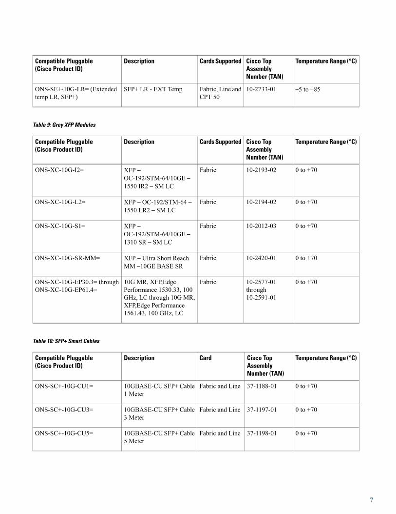
Temperature Range (°C)Cisco TopAssemblyNumber (TAN)
Cards SupportedDescriptionCompatible Pluggable(Cisco Product ID)
–5 to +8510-2733-01Fabric, Line andCPT 50
SFP+ LR - EXT TempONS-SE+-10G-LR= (Extendedtemp LR, SFP+)
Table 9: Grey XFP Modules
Temperature Range (°C)Cisco TopAssemblyNumber (TAN)
Cards SupportedDescriptionCompatible Pluggable(Cisco Product ID)
0 to +7010-2193-02FabricXFP –OC-192/STM-64/10GE –1550 IR2 – SM LC
ONS-XC-10G-I2=
0 to +7010-2194-02FabricXFP – OC-192/STM-64 –1550 LR2 – SM LC
ONS-XC-10G-L2=
0 to +7010-2012-03FabricXFP –OC-192/STM-64/10GE –1310 SR – SM LC
ONS-XC-10G-S1=
0 to +7010-2420-01FabricXFP – Ultra Short ReachMM –10GE BASE SR
ONS-XC-10G-SR-MM=
0 to +7010-2577-01through10-2591-01
Fabric10G MR, XFP,EdgePerformance 1530.33, 100GHz, LC through 10G MR,XFP,Edge Performance1561.43, 100 GHz, LC
ONS-XC-10G-EP30.3= throughONS-XC-10G-EP61.4=
Table 10: SFP+ Smart Cables
Temperature Range (°C)Cisco TopAssemblyNumber (TAN)
CardDescriptionCompatible Pluggable(Cisco Product ID)
0 to +7037-1188-01Fabric and Line10GBASE-CU SFP+ Cable1 Meter
ONS-SC+-10G-CU1=
0 to +7037-1197-01Fabric and Line10GBASE-CU SFP+ Cable3 Meter
ONS-SC+-10G-CU3=
0 to +7037-1198-01Fabric and Line10GBASE-CU SFP+ Cable5 Meter
ONS-SC+-10G-CU5=
7

Temperature Range (°C)Cisco TopAssemblyNumber (TAN)
CardDescriptionCompatible Pluggable(Cisco Product ID)
0 to +7037-1196-01Fabric and Line10GBASE-CU SFP+ Cable7 Meter
ONS-SC+-10G-CU7=
SFP and SFP+ Description and Specifications
The SFP modules are integrated fiber optic transceivers that provide high speed serial links from a port or slot to the network. TheSFP+ transceiver is an enhancement over the SFP optics developed for 1 Gbps Ethernet and 1 Gbps, 2 Gbps, and 4 Gbps FibreChannel. The SFP+ modules extend the data rate up to 11.10 Gbps. SFP+ modules also provide 2-wire serial, I2C interface. The I2Cinterface is used for serial ID, digital diagnostics, and module control functions.
Various latching mechanisms can be utilized on the SFP and SFP+ modules. There is no correlation between the type of latch andthe model type (such as SX or LX/LH) or technology type (such as Gigabit Ethernet). See the label on the SFP and SFP+ modulesfor technology type and model. One type of latch available is a mylar tab as shown in Figure 1: Mylar Tab SFP, a second type oflatch is an actuator/button (Figure 2: Actuator/Button SFP), and the third type of latch is a bail clasp (Figure 3: Bail Clasp SFP andFigure 4: Wide Bail Clasp SFP ).
SFP and SFP+ module dimensions are:
• Height 0.33 inches (8.5 mm)
•Width 0.53 inches (13.4 mm)
• Depth 2.22 inches (56.5 mm)
SFP and SFP+ module temperature ranges are:
• COM—Commercial operating temperature range between 23 degrees Fahrenheit to 158 degrees Fahrenheit (–5 degrees Celsiusto 70 degrees Celsius)
• EXT—Extended operating temperature range between 23 degrees Fahrenheit it to 185 degrees Fahrenheit (–5 degrees Celsiusto 85 degrees Celsius)
• IND—Industrial operating temperature range between –40 degrees Fahrenheit to 185 degrees Fahrenheit (–40 degrees Celsiusto 85 degrees Celsius)
8

Do not add labels or markings to the SFP and SFP+ modules.Caution
Figure 1: Mylar Tab SFP
Figure 2: Actuator/Button SFP
Figure 3: Bail Clasp SFP
Figure 4: Wide Bail Clasp SFP
SFP SpecificationsThe following table lists specifications for available SFPs.
Important note for the following table:
• The LED based SFPs ( ONS-SI-100-FX) do not support the optical power transmitted (OPT) and laser bias current (LBC)optical parameters.
9
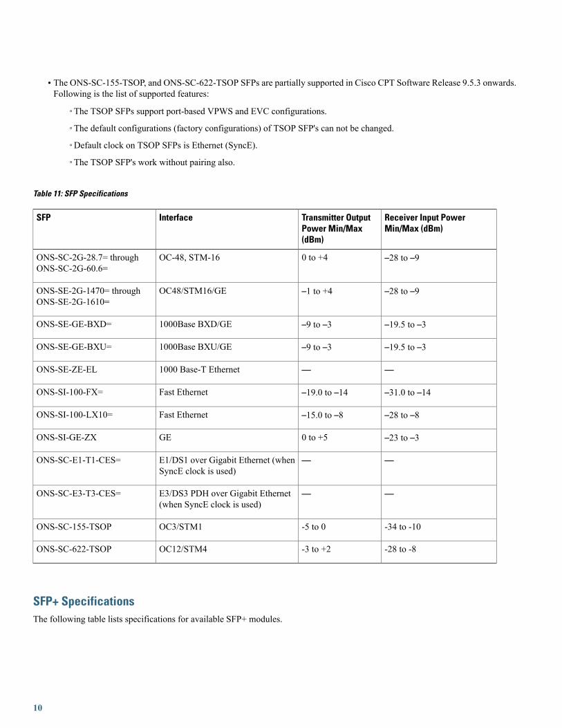
• The ONS-SC-155-TSOP, and ONS-SC-622-TSOP SFPs are partially supported in Cisco CPT Software Release 9.5.3 onwards.Following is the list of supported features:
◦The TSOP SFPs support port-based VPWS and EVC configurations.
◦The default configurations (factory configurations) of TSOP SFP's can not be changed.
◦Default clock on TSOP SFPs is Ethernet (SyncE).
◦The TSOP SFP's work without pairing also.
Table 11: SFP Specifications
Receiver Input PowerMin/Max (dBm)
Transmitter OutputPower Min/Max(dBm)
InterfaceSFP
–28 to –90 to +4OC-48, STM-16ONS-SC-2G-28.7= throughONS-SC-2G-60.6=
–28 to –9–1 to +4OC48/STM16/GEONS-SE-2G-1470= throughONS-SE-2G-1610=
–19.5 to –3–9 to –31000Base BXD/GEONS-SE-GE-BXD=
–19.5 to –3–9 to –31000Base BXU/GEONS-SE-GE-BXU=
——1000 Base-T EthernetONS-SE-ZE-EL
–31.0 to –14–19.0 to –14Fast EthernetONS-SI-100-FX=
–28 to –8–15.0 to –8Fast EthernetONS-SI-100-LX10=
–23 to –30 to +5GEONS-SI-GE-ZX
——E1/DS1 over Gigabit Ethernet (whenSyncE clock is used)
ONS-SC-E1-T1-CES=
——E3/DS3 PDH over Gigabit Ethernet(when SyncE clock is used)
ONS-SC-E3-T3-CES=
-34 to -10-5 to 0OC3/STM1ONS-SC-155-TSOP
-28 to -8-3 to +2OC12/STM4ONS-SC-622-TSOP
SFP+ SpecificationsThe following table lists specifications for available SFP+ modules.
10

Table 12: SFP+ Specifications
Receiver Input Power Min/Max (dBm)TransmitterOutput PowerMin/Max (dBm)
InterfaceSFP+
–15.8 to –1.0–4.7 to +4.010GBASE-ERONS-SC+-10G-ER=
–14.1 to +0.5–8.2 to +0.510GBASE-LRONS-SC+-10G-LR=
–8.4 (in average) to +0.5–6.4 (in OMA) to +0.5
–6.5 to +0.510GBASE-LRMONS-SC+-10G-LRM=
–9.9 to –1.0–7.3 to –1.210GBASE-SRONS-SC+-10G-SR=
–11 to –1–7.3 to –1.310GBASE-ZRONS-SC+-10G-ZR=
11
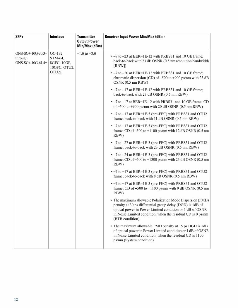
Receiver Input Power Min/Max (dBm)TransmitterOutput PowerMin/Max (dBm)
InterfaceSFP+
• –7 to –23 at BER=1E-12 with PRBS31 and 10 GE frame;back-to-back with 23 dB OSNR (0.5 nm resolution bandwidth[RBW])
• –7 to –20 at BER=1E-12 with PRBS31 and 10 GE frame;chromatic dispersion (CD) of –500 to +900 ps/nm with 23 dBOSNR (0.5 nm RBW)
• –7 to –17 at BER=1E-12 with PRBS31 and 10 GE frame;back-to-back with 23 dB OSNR (0.5 nm RBW)
• –7 to –17 at BER=1E-12 with PRBS31 and 10 GE frame; CDof –500 to +900 ps/nm with 20 dB OSNR (0.5 nm RBW)
• –7 to –17 at BER=1E-5 (pre-FEC) with PRBS31 and OTU2frame; back-to-back with 11 dB OSNR (0.5 nm RBW)
• –7 to –17 at BER=1E-5 (pre-FEC) with PRBS31 and OTU2frame; CD of –500 to +1100 ps/nm with 12 dB OSNR (0.5 nmRBW)
• –7 to –27 at BER=1E-3 (pre-FEC) with PRBS31 and OTU2frame; back-to-back with 23 dB OSNR (0.5 nm RBW)
• –7 to –24 at BER=1E-3 (pre-FEC) with PRBS31 and OTU2frame; CD of –500 to +1300 ps/nm with 23 dB OSNR (0.5 nmRBW)
• –7 to –17 at BER=1E-3 (pre-FEC) with PRBS31 and OTU2frame; back-to-back with 8 dB OSNR (0.5 nm RBW)
• –7 to –17 at BER=1E-3 (pre-FEC) with PRBS31 and OTU2frame; CD of –500 to +1100 ps/nm with 9 dB OSNR (0.5 nmRBW)
• Themaximum allowable PolarizationModeDispersion (PMD)penalty at 30 ps differential group delay (DGD) is 1dB ofoptical power in Power Limited condition or 1 dB of OSNRin Noise Limited condition, when the residual CD is 0 ps/nm(BTB condition).
• The maximum allowable PMD penalty at 15 ps DGD is 1dBof optical power in Power Limited condition or 1 dB of OSNRin Noise Limited condition, when the residual CD is 1100ps/nm (System condition).
–1.0 to +3.0OC-192,STM-64,8GFC, 10GE,10GFC, OTU2,OTU2e
ONS-SC+-10G-30.3=throughONS-SC+-10G-61.4=
12
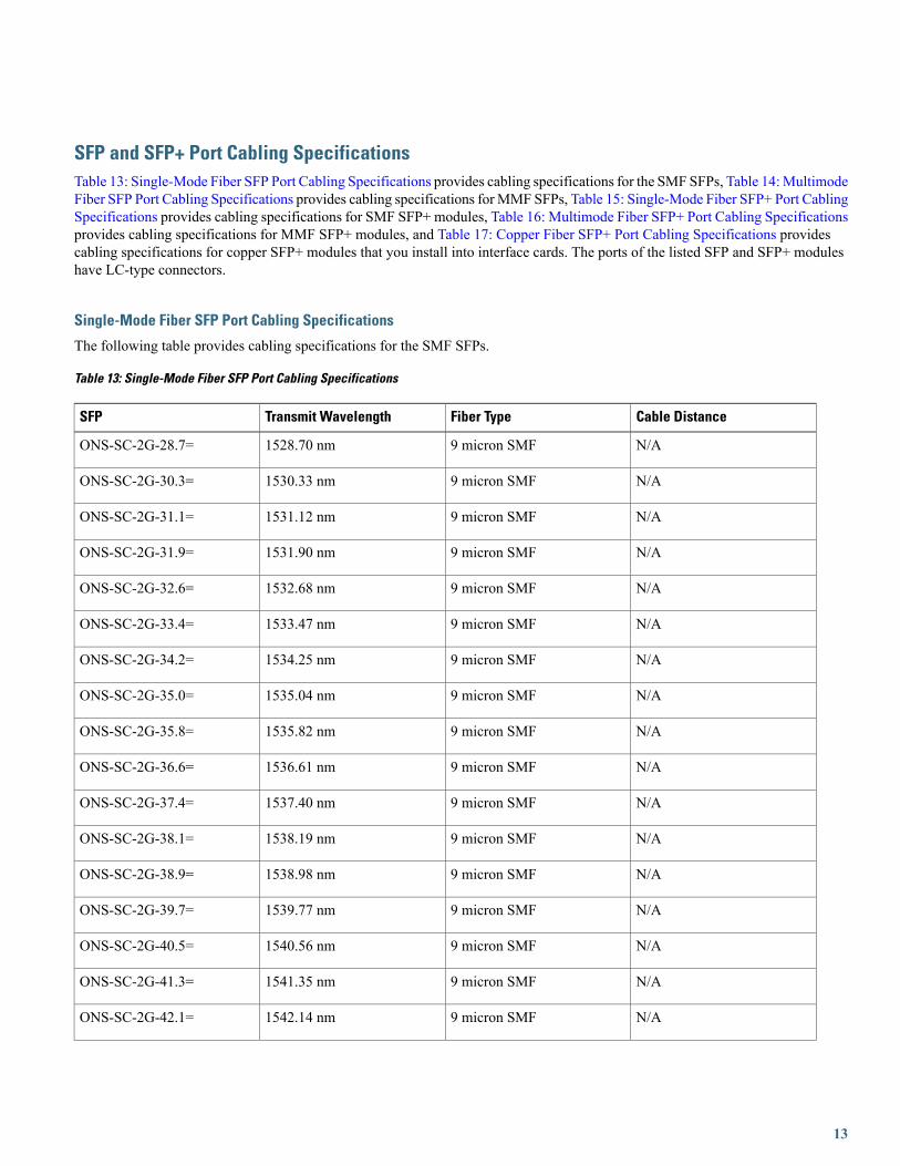
SFP and SFP+ Port Cabling SpecificationsTable 13: Single-Mode Fiber SFP Port Cabling Specifications provides cabling specifications for the SMF SFPs, Table 14:MultimodeFiber SFP Port Cabling Specifications provides cabling specifications forMMF SFPs, Table 15: Single-Mode Fiber SFP+ Port CablingSpecifications provides cabling specifications for SMF SFP+ modules, Table 16: Multimode Fiber SFP+ Port Cabling Specificationsprovides cabling specifications for MMF SFP+ modules, and Table 17: Copper Fiber SFP+ Port Cabling Specifications providescabling specifications for copper SFP+ modules that you install into interface cards. The ports of the listed SFP and SFP+ moduleshave LC-type connectors.
Single-Mode Fiber SFP Port Cabling Specifications
The following table provides cabling specifications for the SMF SFPs.
Table 13: Single-Mode Fiber SFP Port Cabling Specifications
Cable DistanceFiber TypeTransmit WavelengthSFP
N/A9 micron SMF1528.70 nmONS-SC-2G-28.7=
N/A9 micron SMF1530.33 nmONS-SC-2G-30.3=
N/A9 micron SMF1531.12 nmONS-SC-2G-31.1=
N/A9 micron SMF1531.90 nmONS-SC-2G-31.9=
N/A9 micron SMF1532.68 nmONS-SC-2G-32.6=
N/A9 micron SMF1533.47 nmONS-SC-2G-33.4=
N/A9 micron SMF1534.25 nmONS-SC-2G-34.2=
N/A9 micron SMF1535.04 nmONS-SC-2G-35.0=
N/A9 micron SMF1535.82 nmONS-SC-2G-35.8=
N/A9 micron SMF1536.61 nmONS-SC-2G-36.6=
N/A9 micron SMF1537.40 nmONS-SC-2G-37.4=
N/A9 micron SMF1538.19 nmONS-SC-2G-38.1=
N/A9 micron SMF1538.98 nmONS-SC-2G-38.9=
N/A9 micron SMF1539.77 nmONS-SC-2G-39.7=
N/A9 micron SMF1540.56 nmONS-SC-2G-40.5=
N/A9 micron SMF1541.35 nmONS-SC-2G-41.3=
N/A9 micron SMF1542.14 nmONS-SC-2G-42.1=
13

Cable DistanceFiber TypeTransmit WavelengthSFP
N/A9 micron SMF1542.94 nmONS-SC-2G-42.9=
N/A9 micron SMF1543.73 nmONS-SC-2G-43.7=
N/A9 micron SMF1544.53 nmONS-SC-2G-44.5=
N/A9 micron SMF1545.32 nmONS-SC-2G-45.3=
N/A9 micron SMF1546.12 nmONS-SC-2G-46.1=
N/A9 micron SMF1546.92 nmONS-SC-2G-46.9=
N/A9 micron SMF1547.72 nmONS-SC-2G-47.7=
N/A9 micron SMF1548.51 nmONS-SC-2G-48.5=
N/A9 micron SMF1549.32 nmONS-SC-2G-49.3=
N/A9 micron SMF1550.12 nmONS-SC-2G-50.1=
N/A9 micron SMF1550.92 nmONS-SC-2G-50.9=
N/A9 micron SMF1551.72 nmONS-SC-2G-51.7=
N/A9 micron SMF1552.52 nmONS-SC-2G-52.5=
N/A9 micron SMF1553.33 nmONS-SC-2G-53.3=
N/A9 micron SMF1554.13 nmONS-SC-2G-54.1=
N/A9 micron SMF1554.94 nmONS-SC-2G-54.9=
N/A9 micron SMF1555.75 nmONS-SC-2G-55.7=
N/A9 micron SMF1556.55 nmONS-SC-2G-56.5=
N/A9 micron SMF1557.36 nmONS-SC-2G-57.3=
N/A9 micron SMF1558.17 nmONS-SC-2G-58.1=
N/A9 micron SMF1558.98 nmONS-SC-2G-58.9=
N/A9 micron SMF1559.79 nmONS-SC-2G-59.7=
N/A9 micron SMF1560.61 nmONS-SC-2G-60.6=
80 km (49.71 miles)9 micron SMF1550 nmONS-SI-GE-ZX=
14

Cable DistanceFiber TypeTransmit WavelengthSFP
80 km (49.71 miles)9 micron SMF1550 nmONS-SE-GE-BXD=
80 km (49.71 miles)9 micron SMF1550 nmONS-SE-GE-BXU=
1.83 km (1.136 miles)9 micron SMF—ONS-SC-E1-T1-CES=
1.83 km (1.136 miles)9 micron SMF—ONS-SC-E3-T3-CES=
2 km (1.24 miles)9 micron SMF1310 nmONS-SI-100-LX10=
40 km (24.85 miles)9 micron SMF1310 nmONS-SC-155-TSOP
40 km (24.85 miles)9 micron SMF1310 nmONS-SC-622-TSOP
Multimode Fiber SFP Port Cabling Specifications
The following table provides cabling specifications for the MMF SFPs.
Table 14: Multimode Fiber SFP Port Cabling Specifications
Cable DistanceFiber TypeTransmit WavelengthSFP
2 km (1.24 miles)MMF1310 nmONS-SI-100-FX=
Single-Mode Fiber SFP+ Port Cabling Specifications
The following table provides cabling specifications for the SMF SFP+ modules.
Table 15: Single-Mode Fiber SFP+ Port Cabling Specifications
Cable DistanceFiber TypeTransmit WavelengthSFP+
40 km (24.85 miles)9 micron SMF1550 nmONS-SC+-10G-ER=
10 km (6.214 miles)9 micron SMF1310 nmONS-SC+-10G-LR=
220 m to 300 m9 micron SMF1310 nmONS-SC+-10G-LRM=
40 km (24.85 miles)9 micron SMF1530.3 - 1561.4 nmONS-SC+-10G-30.3= throughONS-SC+-10G-61.4=
Multimode Fiber SFP+ Port Cabling Specifications
The following table provides cabling specifications for the MMF SFP+ modules.
15
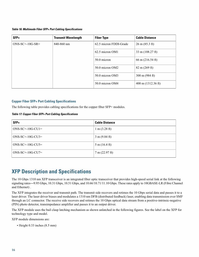
Table 16: Multimode Fiber SFP+ Port Cabling Specifications
Cable DistanceFiber TypeTransmit WavelengthSFP+
26 m (85.3 ft)62.5 micron FDDI-Grade840-860 nmONS-SC+-10G-SR=
33 m (108.27 ft)62.5 micron OM1
66 m (216.54 ft)50.0 micron
82 m (269 ft)50.0 micron OM2
300 m (984 ft)50.0 micron OM3
400 m (1312.36 ft)50.0 micron OM4
Copper Fiber SFP+ Port Cabling Specifications
The following table provides cabling specifications for the copper fiber SFP+ modules.
Table 17: Copper Fiber SFP+ Port Cabling Specifications
Cable DistanceSFP+
1 m (3.28 ft)ONS-SC+-10G-CU1=
3 m (9.84 ft)ONS-SC+-10G-CU3=
5 m (16.4 ft)ONS-SC+-10G-CU5=
7 m (22.97 ft)ONS-SC+-10G-CU7=
XFP Description and SpecificationsThe 10 Gbps 1310 nm XFP transceiver is an integrated fiber optic transceiver that provides high-speed serial link at the followingsignaling rates—9.95 Gbps, 10.31 Gbps, 10.51 Gbps, and 10.66/10.71/11.10 Gbps. These rates apply to 10GBASE-LR (Fibre Channeland Ethernet) .
The XFP integrates the receiver and transmit path. The transmit side recovers and retimes the 10 Gbps serial data and passes it to alaser driver. The laser driver biases and modulates a 1310 nm DFB (distributed feedback) laser, enabling data transmission over SMFthrough an LC connector. The receive side recovers and retimes the 10 Gbps optical data stream from a positive-intrinsic-negative(PIN) photo detector, transimpedance amplifier and passes it to an output driver.
The XFP module uses the bail clasp latching mechanism as shown unlatched in the following figures. See the label on the XFP fortechnology type and model.
XFP module dimensions are:
• Height 0.33 inches (8.5 mm)
16

•Width 0.72 inches (18.3 mm)
• Depth 3.1 inches (78 mm)
XFP temperature ranges are:
• COM—Commercial operating temperature range between 23 degrees Fahrenheit to 158 degrees Fahrenheit (-5 degrees Celsiusto 70 degrees Celsius)
• EXT—Extended operating temperature range between 23 degrees Fahrenheit it to 185 degrees Fahrenheit (-5 degrees Celsiusto 85 degrees Celsius)
• IND—Industrial operating temperature range between -40 degrees Fahrenheit to 185 degrees Fahrenheit (-40 degrees Celsiusto 85 degrees Celsius)
Do not add labels or markings to the XFP modules.Caution
Figure 5: Bail Clasp XFP (Unlatched)
Figure 6: Bail Clasp XFP (Latched)
XFP SpecificationsThe following table lists specifications for available XFPs.
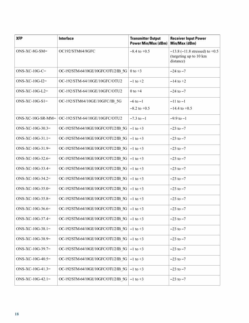
Table 18: XFP Specifications
Receiver Input PowerMin/Max (dBm)
Transmitter OutputPower Min/Max (dBm)
InterfaceXFP
0.151 mW (stressed receivedin OMA)
–8.2 to –1.5OC192/STM64/8GFCONS-XC-8G-MM=
17
Receiver Input PowerMin/Max (dBm)
Transmitter OutputPower Min/Max (dBm)
InterfaceXFP
–13.8 (–11.8 stressed) to +0.5(targeting up to 10 kmdistance)
–8.4 to +0.5OC192/STM64/8GFCONS-XC-8G-SM=
–24 to –70 to +3OC-192/STM-64/10GE/10GFC/OTU2/IB_5GONS-XC-10G-C=
–14 to +2–1 to +2OC-192/STM-64/10GE/10GFC/OTU2ONS-XC-10G-I2=
–24 to –70 to +4OC-192/STM-64/10GE/10GFC/OTU2ONS-XC-10G-L2=
–11 to –1–14.4 to +0.5
–6 to –1–8.2 to +0.5
OC-192/STM64/10GE/10GFC/IB_5GONS-XC-10G-S1=
–9.9 to –1–7.3 to –1OC-192/STM-64/10GE/10GFC/OTU2ONS-XC-10G-SR-MM=
–23 to –7–1 to +3OC-192/STM-64/10GE/10GFC/OTU2/IB_5GONS-XC-10G-30.3=
–23 to –7–1 to +3OC-192/STM-64/10GE/10GFC/OTU2/IB_5GONS-XC-10G-31.1=
–23 to –7–1 to +3OC-192/STM-64/10GE/10GFC/OTU2/IB_5GONS-XC-10G-31.9=
–23 to –7–1 to +3OC-192/STM-64/10GE/10GFC/OTU2/IB_5GONS-XC-10G-32.6=
–23 to –7–1 to +3OC-192/STM-64/10GE/10GFC/OTU2/IB_5GONS-XC-10G-33.4=
–23 to –7–1 to +3OC-192/STM-64/10GE/10GFC/OTU2/IB_5GONS-XC-10G-34.2=
–23 to –7–1 to +3OC-192/STM-64/10GE/10GFC/OTU2/IB_5GONS-XC-10G-35.0=
–23 to –7–1 to +3OC-192/STM-64/10GE/10GFC/OTU2/IB_5GONS-XC-10G-35.8=
–23 to –7–1 to +3OC-192/STM-64/10GE/10GFC/OTU2/IB_5GONS-XC-10G-36.6=
–23 to –7–1 to +3OC-192/STM-64/10GE/10GFC/OTU2/IB_5GONS-XC-10G-37.4=
–23 to –7–1 to +3OC-192/STM-64/10GE/10GFC/OTU2/IB_5GONS-XC-10G-38.1=
–23 to –7–1 to +3OC-192/STM-64/10GE/10GFC/OTU2/IB_5GONS-XC-10G-38.9=
–23 to –7–1 to +3OC-192/STM-64/10GE/10GFC/OTU2/IB_5GONS-XC-10G-39.7=
–23 to –7–1 to +3OC-192/STM-64/10GE/10GFC/OTU2/IB_5GONS-XC-10G-40.5=
–23 to –7–1 to +3OC-192/STM-64/10GE/10GFC/OTU2/IB_5GONS-XC-10G-41.3=
–23 to –7–1 to +3OC-192/STM-64/10GE/10GFC/OTU2/IB_5GONS-XC-10G-42.1=
18
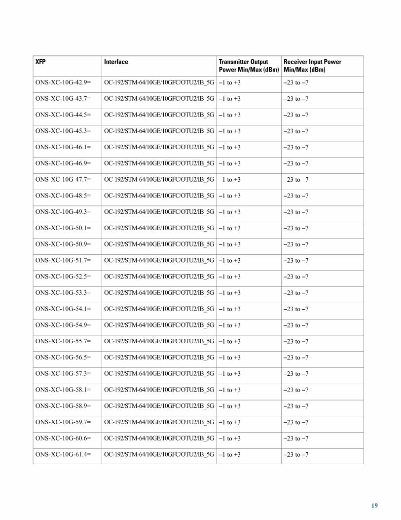
Receiver Input PowerMin/Max (dBm)
Transmitter OutputPower Min/Max (dBm)
InterfaceXFP
–23 to –7–1 to +3OC-192/STM-64/10GE/10GFC/OTU2/IB_5GONS-XC-10G-42.9=
–23 to –7–1 to +3OC-192/STM-64/10GE/10GFC/OTU2/IB_5GONS-XC-10G-43.7=
–23 to –7–1 to +3OC-192/STM-64/10GE/10GFC/OTU2/IB_5GONS-XC-10G-44.5=
–23 to –7–1 to +3OC-192/STM-64/10GE/10GFC/OTU2/IB_5GONS-XC-10G-45.3=
–23 to –7–1 to +3OC-192/STM-64/10GE/10GFC/OTU2/IB_5GONS-XC-10G-46.1=
–23 to –7–1 to +3OC-192/STM-64/10GE/10GFC/OTU2/IB_5GONS-XC-10G-46.9=
–23 to –7–1 to +3OC-192/STM-64/10GE/10GFC/OTU2/IB_5GONS-XC-10G-47.7=
–23 to –7–1 to +3OC-192/STM-64/10GE/10GFC/OTU2/IB_5GONS-XC-10G-48.5=
–23 to –7–1 to +3OC-192/STM-64/10GE/10GFC/OTU2/IB_5GONS-XC-10G-49.3=
–23 to –7–1 to +3OC-192/STM-64/10GE/10GFC/OTU2/IB_5GONS-XC-10G-50.1=
–23 to –7–1 to +3OC-192/STM-64/10GE/10GFC/OTU2/IB_5GONS-XC-10G-50.9=
–23 to –7–1 to +3OC-192/STM-64/10GE/10GFC/OTU2/IB_5GONS-XC-10G-51.7=
–23 to –7–1 to +3OC-192/STM-64/10GE/10GFC/OTU2/IB_5GONS-XC-10G-52.5=
–23 to –7–1 to +3OC-192/STM-64/10GE/10GFC/OTU2/IB_5GONS-XC-10G-53.3=
–23 to –7–1 to +3OC-192/STM-64/10GE/10GFC/OTU2/IB_5GONS-XC-10G-54.1=
–23 to –7–1 to +3OC-192/STM-64/10GE/10GFC/OTU2/IB_5GONS-XC-10G-54.9=
–23 to –7–1 to +3OC-192/STM-64/10GE/10GFC/OTU2/IB_5GONS-XC-10G-55.7=
–23 to –7–1 to +3OC-192/STM-64/10GE/10GFC/OTU2/IB_5GONS-XC-10G-56.5=
–23 to –7–1 to +3OC-192/STM-64/10GE/10GFC/OTU2/IB_5GONS-XC-10G-57.3=
–23 to –7–1 to +3OC-192/STM-64/10GE/10GFC/OTU2/IB_5GONS-XC-10G-58.1=
–23 to –7–1 to +3OC-192/STM-64/10GE/10GFC/OTU2/IB_5GONS-XC-10G-58.9=
–23 to –7–1 to +3OC-192/STM-64/10GE/10GFC/OTU2/IB_5GONS-XC-10G-59.7=
–23 to –7–1 to +3OC-192/STM-64/10GE/10GFC/OTU2/IB_5GONS-XC-10G-60.6=
–23 to –7–1 to +3OC-192/STM-64/10GE/10GFC/OTU2/IB_5GONS-XC-10G-61.4=
19

Receiver Input PowerMin/Max (dBm)
Transmitter OutputPower Min/Max (dBm)
InterfaceXFP
–14 to –0+3 to +7OC-192/STM-64/10GE/10GFC/OTU2ONS-XC-10G-1470=
–14 to –0+3 to +7OC-192/STM-64/10GE/10GFC/OTU2ONS-XC-10G-1490=
–14 to –0+3 to +7OC-192/STM-64/10GE/10GFC/OTU2ONS-XC-10G-1510=
–14 to –0+3 to +7OC-192/STM-64/10GE/10GFC/OTU2ONS-XC-10G-1530=
–14 to –0+3 to +7OC-192/STM-64/10GE/10GFC/OTU2ONS-XC-10G-1550=
–14 to –0+3 to +7OC-192/STM-64/10GE/10GFC/OTU2ONS-XC-10G-1570=
–14 to –0+3 to +7OC-192/STM-64/10GE/10GFC/OTU2ONS-XC-10G-1590=
–14 to –0+3 to +7OC-192/STM-64/10GE/10GFC/OTU2ONS-XC-10G-1610=
–27 to –8–1 to +3OC-192/STM-64/10GE/10GFC/OTU2ONS-XC-10G-EP30.3=
–27 to –8–1 to +3OC-192/STM-64/10GE/10GFC/OTU2ONS-XC-10G-EP31.1=
–27 to –8–1 to +3OC-192/STM-64/10GE/10GFC/OTU2ONS-XC-10G-EP31.9=
–27 to –8–1 to +3OC-192/STM-64/10GE/10GFC/OTU2ONS-XC-10G-EP32.6=
–27 to –8–1 to +3OC-192/STM-64/10GE/10GFC/OTU2ONS-XC-10G-EP33.4=
–27 to –8–1 to +3OC-192/STM-64/10GE/10GFC/OTU2ONS-XC-10G-EP34.2=
–27 to –8–1 to +3OC-192/STM-64/10GE/10GFC/OTU2ONS-XC-10G-EP35.0=
–27 to –8–1 to +3OC-192/STM-64/10GE/10GFC/OTU2ONS-XC-10G-EP35.8=
–27 to –8–1 to +3OC-192/STM-64/10GE/10GFC/OTU2ONS-XC-10G-EP36.6=
–27 to –8–1 to +3OC-192/STM-64/10GE/10GFC/OTU2ONS-XC-10G-EP37.4=
–27 to –8–1 to +3OC-192/STM-64/10GE/10GFC/OTU2ONS-XC-10G-EP38.1=
–27 to –8–1 to +3OC-192/STM-64/10GE/10GFC/OTU2ONS-XC-10G-EP38.9=
–27 to –8–1 to +3OC-192/STM-64/10GE/10GFC/OTU2ONS-XC-10G-EP39.7=
–27 to –8–1 to +3OC-192/STM-64/10GE/10GFC/OTU2ONS-XC-10G-EP40.5=
–27 to –8–1 to +3OC-192/STM-64/10GE/10GFC/OTU2ONS-XC-10G-EP41.3=
–27 to –8–1 to +3OC-192/STM-64/10GE/10GFC/OTU2ONS-XC-10G-EP42.1=
20

Receiver Input PowerMin/Max (dBm)
Transmitter OutputPower Min/Max (dBm)
InterfaceXFP
–27 to –8–1 to +3OC-192/STM-64/10GE/10GFC/OTU2ONS-XC-10G-EP42.9=
–27 to –8–1 to +3OC-192/STM-64/10GE/10GFC/OTU2ONS-XC-10G-EP43.7=
–27 to –8–1 to +3OC-192/STM-64/10GE/10GFC/OTU2ONS-XC-10G-EP44.5=
–27 to –8–1 to +3OC-192/STM-64/10GE/10GFC/OTU2ONS-XC-10G-EP45.3=
–27 to –8–1 to +3OC-192/STM-64/10GE/10GFC/OTU2ONS-XC-10G-EP46.1=
–27 to –8–1 to +3OC-192/STM-64/10GE/10GFC/OTU2ONS-XC-10G-EP46.9=
–27 to –8–1 to +3OC-192/STM-64/10GE/10GFC/OTU2ONS-XC-10G-EP47.7=
–27 to –8–1 to +3OC-192/STM-64/10GE/10GFC/OTU2ONS-XC-10G-EP48.5=
–27 to –8–1 to +3OC-192/STM-64/10GE/10GFC/OTU2ONS-XC-10G-EP49.3=
–27 to –8–1 to +3OC-192/STM-64/10GE/10GFC/OTU2ONS-XC-10G-EP50.1=
–27 to –8–1 to +3OC-192/STM-64/10GE/10GFC/OTU2ONS-XC-10G-EP50.9=
–27 to –8–1 to +3OC-192/STM-64/10GE/10GFC/OTU2ONS-XC-10G-EP51.7=
–27 to –8–1 to +3OC-192/STM-64/10GE/10GFC/OTU2ONS-XC-10G-EP52.5=
–27 to –8–1 to +3OC-192/STM-64/10GE/10GFC/OTU2ONS-XC-10G-EP53.3=
–27 to –8–1 to +3OC-192/STM-64/10GE/10GFC/OTU2ONS-XC-10G-EP54.1=
–27 to –8–1 to +3OC-192/STM-64/10GE/10GFC/OTU2ONS-XC-10G-EP54.9=
–27 to –8–1 to +3OC-192/STM-64/10GE/10GFC/OTU2ONS-XC-10G-EP55.7=
–27 to –8–1 to +3OC-192/STM-64/10GE/10GFC/OTU2ONS-XC-10G-EP56.5=
–27 to –8–1 to +3OC-192/STM-64/10GE/10GFC/OTU2ONS-XC-10G-EP57.3=
–27 to –8–1 to +3OC-192/STM-64/10GE/10GFC/OTU2ONS-XC-10G-EP58.1=
–27 to –8–1 to +3OC-192/STM-64/10GE/10GFC/OTU2ONS-XC-10G-EP58.9=
–27 to –8–1 to +3OC-192/STM-64/10GE/10GFC/OTU2ONS-XC-10G-EP59.7=
–27 to –8–1 to +3OC-192/STM-64/10GE/10GFC/OTU2ONS-XC-10G-EP60.6=
–27 to –8–1 to +3OC-192/STM-64/10GE/10GFC/OTU2ONS-XC-10G-EP61.4=
21

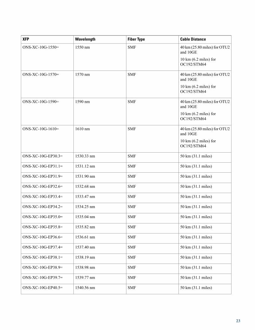
Single-Mode Fiber XFP Port Cabling SpecificationsThe following table lists specifications for single-mode fiber XFP port cabling.
Table 19: Single-Mode Fiber XFP Port Cabling Specifications
Cable DistanceFiber TypeWavelengthXFP
80 km (49.71 miles) forOC-192/STM64/10GE
SMF1529.55 nm through 1561.83nm, with ITU spacing
ONS-XC-10G-C=
40 km (25.80 miles) forOC-192/STM64
SMFReceiver: 1260 nm to 1565 nm
Transmitter: 1530 nm to 1565nm
ONS-XC-10G-I2=
80 km (49.71 miles) forOC-192/STM64
SMFTransmitter: 1530 nm to 1565nm
Receiver: 1260 nm to 1565 nm
ONS-XC-10G-L2=
10 km (6.2 miles) for10GE/10GFC
2 km (1.2 miles) forOC-192/STM64
SMF1310 nmONS-XC-10G-S1=
40 km (25.80miles) for OTU2and 10GE
10 km (6.2 miles) forOC192/STM64
SMF1470 nmONS-XC-10G-1470=
40 km (25.80miles) for OTU2and 10GE
10 km (6.2 miles) forOC192/STM64
SMF1490 nmONS-XC-10G-1490=
40 km (25.80miles) for OTU2and 10GE
10 km (6.2 miles) forOC192/STM64
SMF1510 nmONS-XC-10G-1510=
40 km (25.80miles) for OTU2and 10GE
10 km (6.2 miles) forOC192/STM64
SMF1530 nmONS-XC-10G-1530=
22
Cable DistanceFiber TypeWavelengthXFP
40 km (25.80miles) for OTU2and 10GE
10 km (6.2 miles) forOC192/STM64
SMF1550 nmONS-XC-10G-1550=
40 km (25.80miles) for OTU2and 10GE
10 km (6.2 miles) forOC192/STM64
SMF1570 nmONS-XC-10G-1570=
40 km (25.80miles) for OTU2and 10GE
10 km (6.2 miles) forOC192/STM64
SMF1590 nmONS-XC-10G-1590=
40 km (25.80miles) for OTU2and 10GE
10 km (6.2 miles) forOC192/STM64
SMF1610 nmONS-XC-10G-1610=
50 km (31.1 miles)SMF1530.33 nmONS-XC-10G-EP30.3=
50 km (31.1 miles)SMF1531.12 nmONS-XC-10G-EP31.1=
50 km (31.1 miles)SMF1531.90 nmONS-XC-10G-EP31.9=
50 km (31.1 miles)SMF1532.68 nmONS-XC-10G-EP32.6=
50 km (31.1 miles)SMF1533.47 nmONS-XC-10G-EP33.4=
50 km (31.1 miles)SMF1534.25 nmONS-XC-10G-EP34.2=
50 km (31.1 miles)SMF1535.04 nmONS-XC-10G-EP35.0=
50 km (31.1 miles)SMF1535.82 nmONS-XC-10G-EP35.8=
50 km (31.1 miles)SMF1536.61 nmONS-XC-10G-EP36.6=
50 km (31.1 miles)SMF1537.40 nmONS-XC-10G-EP37.4=
50 km (31.1 miles)SMF1538.19 nmONS-XC-10G-EP38.1=
50 km (31.1 miles)SMF1538.98 nmONS-XC-10G-EP38.9=
50 km (31.1 miles)SMF1539.77 nmONS-XC-10G-EP39.7=
50 km (31.1 miles)SMF1540.56 nmONS-XC-10G-EP40.5=
23

Cable DistanceFiber TypeWavelengthXFP
50 km (31.1 miles)SMF1541.35 nmONS-XC-10G-EP41.3=
50 km (31.1 miles)SMF1542.14 nmONS-XC-10G-EP42.1=
50 km (31.1 miles)SMF1542.94 nmONS-XC-10G-EP42.9=
50 km (31.1 miles)SMF1543.73 nmONS-XC-10G-EP43.7=
50 km (31.1 miles)SMF1544.53 nmONS-XC-10G-EP44.5=
50 km (31.1 miles)SMF1545.32 nmONS-XC-10G-EP45.3=
50 km (31.1 miles)SMF1546.12 nmONS-XC-10G-EP46.1=
50 km (31.1 miles)SMF1546.92 nmONS-XC-10G-EP46.9=
50 km (31.1 miles)SMF1547.72 nmONS-XC-10G-EP47.7=
50 km (31.1 miles)SMF1548.51 nmONS-XC-10G-EP48.5=
50 km (31.1 miles)SMF1549.32 nmONS-XC-10G-EP49.3=
50 km (31.1 miles)SMF1550.12 nmONS-XC-10G-EP50.1=
50 km (31.1 miles)SMF1550.92 nmONS-XC-10G-EP50.9=
50 km (31.1 miles)SMF1551.72 nmONS-XC-10G-EP51.7=
50 km (31.1 miles)SMF1552.52 nmONS-XC-10G-EP52.5=
50 km (31.1 miles)SMF1553.33 nmONS-XC-10G-EP53.3=
50 km (31.1 miles)SMF1554.13 nmONS-XC-10G-EP54.1=
50 km (31.1 miles)SMF1554.94 nmONS-XC-10G-EP54.9=
50 km (31.1 miles)SMF1555.75 nmONS-XC-10G-EP55.7=
50 km (31.1 miles)SMF1556.55 nmONS-XC-10G-EP56.5=
50 km (31.1 miles)SMF1557.36 nmONS-XC-10G-EP57.3=
50 km (31.1 miles)SMF1558.17 nmONS-XC-10G-EP58.1=
50 km (31.1 miles)SMF1558.98 nmONS-XC-10G-EP58.9=
50 km (31.1 miles)SMF1559.79 nmONS-XC-10G-EP59.7=
24

Cable DistanceFiber TypeWavelengthXFP
50 km (31.1 miles)SMF1560.61 nmONS-XC-10G-EP60.6=
50 km (31.1 miles)SMF1561.43 nmONS-XC-10G-EP61.4=
Multimode Fiber XFP Port Cabling SpecificationsThe following table lists specifications for multimode fiber XFP port cabling.
Table 20: Multimode Fiber XFP Port Cabling Specifications
Cable DistanceFiber TypeWavelengthXFP
26-300 m (0.1864 miles)
OC-192/STM64/10GE/10GFC/OTU2
MMF840 nm to 860 nmONS-XC-10G-SR-MM=
NTP-G324 Install, Provision, and Delete PPMs
SFP, SFP+, and XFP modules are Class I laser products. Statement 1008Warning
Invisible laser radiation could be emitted from the end of the unterminated fiber cable or connector. Donot stare into the beam directly with optical instruments. Viewing the laser output with certain opticalinstruments (for example, eye loupes, magnifiers, and microscopes) within a distance of 100 mm couldpose an eye hazard. Statement 1056
Warning
Ultimate disposal of this product should be handled according to all national laws and regulations. Statement1040
Warning
Use of controls, adjustments, or performing procedures other than those specified may result in hazardousradiation exposure. Statement 1057
Warning
During this procedure, wear grounding wrist straps to avoid ESD damage to the card. Do not directlytouch the backplane with your hand or any metal tool, or you could shock yourself. Statement 94
Warning
25

Before you install, operate, or service the system, read the Site Preparation and Safety Guide. This guidecontains important safety information you should know before working with the system.
Warning
Only trained and qualified personnel should be allowed to install, replace, or service this equipment.Statement 148
Warning
To comply with the Telcordia GR-1089 NEBS standard for electromagnetic compatibility and safety, forEthernet RJ-45 ports, use only shielded Ethernet cables that are grounded on both ends. In a NEBSinstallation, all Ethernet ports are limited to intra-building wiring. Statement 7012
Warning
Ethernet ports are intra-building ports and are suitable only for connecting to shielded cabling groundedat both ends. Statement 1084
Warning
Do not use SFP, SFP+, and XFPmodules from third-party vendors. Cisco TAC does not support third-partyvendor SFP, SFP+, and XFP modules. A third-party vendor SFP, SFP+, and XFP modules is any SFP,SFP+, or XFP module that is not sourced from Cisco directly, or via a Cisco Partner, or Cisco authorizedseller. Cisco-sourced SFP, SFP+, and XFP modules can be identified by the Cisco label and logo.
Caution
This task installs, provisions, and deletes PPMs (SFP, SFP+, and XFP modules) on the linecards. Because SFP, SFP+, and XFP modules are hot-swappable, they can be installed andremoved while the card/shelf assembly is powered and running.
Purpose
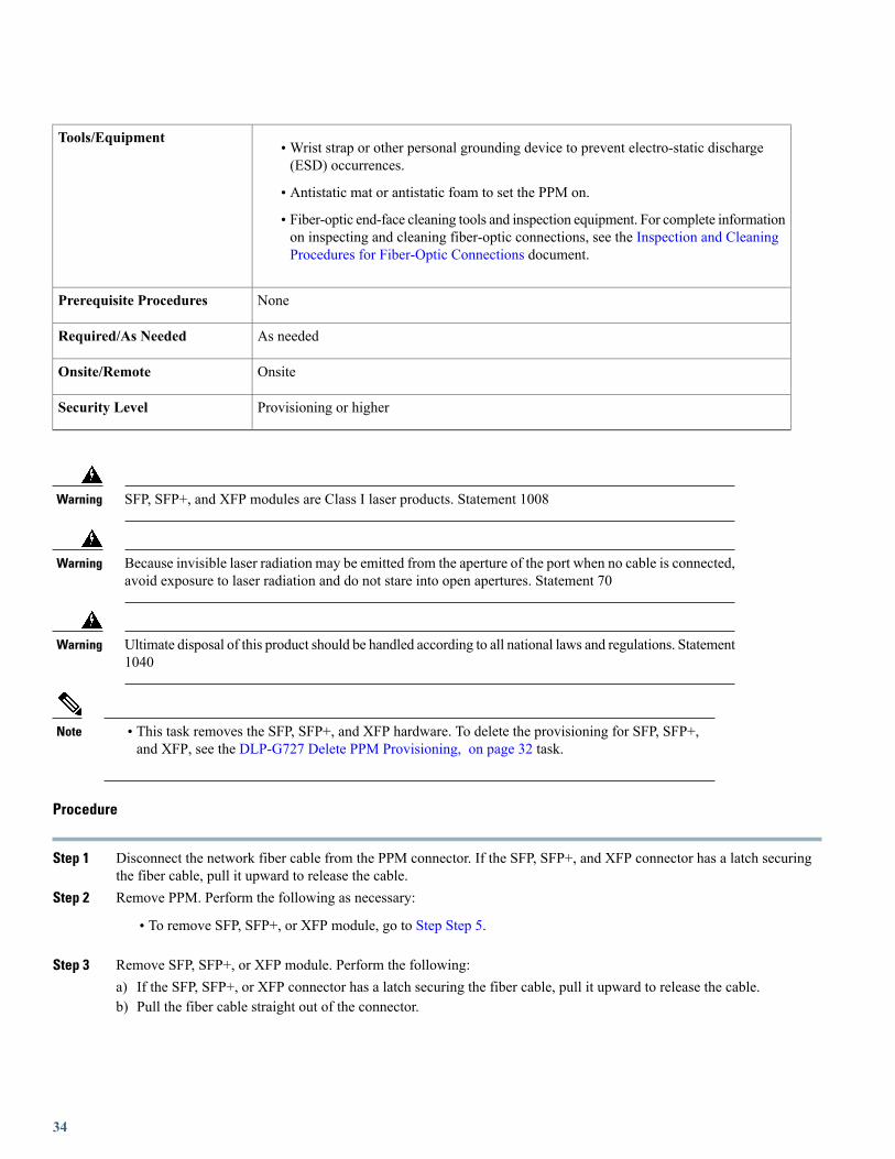
•Wrist strap or other personal grounding device to prevent electro-static discharge (ESD)occurrences.
• Antistatic mat or antistatic foam to set the PPM on.
• Fiber-optic end-face cleaning tools and inspection equipment. For complete informationon inspecting and cleaning fiber-optic connections, see the Inspection and CleaningProcedures for Fiber-Optic Connections document.
Tools/Equipment
"NTP-J19 Install the Fabric and Line Cards" task in the chapter "Hardware" of Cisco CPTConfiguration Guide.
Prerequisite Procedures
As neededRequired/As Needed
OnsiteOnsite/Remote
Provisioning or higherSecurity Level
26

Procedure
Step 1 Install PPMs. Complete the necessary task as applicable:
• DLP-G723 Install PPM on a Line Card, on page 27
• DLP-G724 Connecting Single-Mode and Multimode Optical Fiber, on page 29
Step 2 Provision the PPM. Complete the necessary task as applicable:
• DLP-G725 Preprovisioning PPM Slot, on page 30
• DLP-G726 Preprovisioning a Multirate PPM, on page 31
Step 3 Delete the PPM. Complete the necessary task as applicable:
• DLP-G727 Delete PPM Provisioning, on page 32
• DLP-G728 Remove PPM from the Line Card, on page 33
Stop. You have completed this procedure.
DLP-G723 Install PPM on a Line Card
This task installs PPM on a line card. The PPMs provide a fiber interface to the card.Purpose
•Wrist strap or other personal grounding device to prevent electro-static discharge(ESD) occurrences.
• Antistatic mat or antistatic foam to set the PPM on.
• Fiber-optic end-face cleaning tools and inspection equipment. For completeinformation on inspecting and cleaning fiber-optic connections, see the Inspectionand Cleaning Procedures for Fiber-Optic Connections document.
Tools/Equipment
"NTP-J19 Install the Fabric and Line Cards" task in the chapter "Hardware" of CiscoCPT Configuration Guide.
Prerequisite Procedures
As neededRequired/As Needed
OnsiteOnsite/Remote
Provisioning or higherSecurity Level
27

SFP, SFP+, and XFP modules are Class I laser products. Statement 1008Warning
Because invisible laser radiation may be emitted from the aperture of the port when no cable is connected,avoid exposure to laser radiation and do not stare into open apertures. Statement 70
Warning
Ultimate disposal of this product should be handled according to all national laws and regulations. Statement1040
Warning
Use of controls, adjustments, or performing procedures other than those specified may result in hazardousradiation exposure. Statement 1057
Warning
To comply with the Telcordia GR-1089 NEBS standard for electromagnetic compatibility and safety,connect the serial high-speed WAN interface ports only to intra-building or unexposed wiring or cable.The intrabuilding cable must be shielded and the shield must be grounded at both ends. The intra-buildingport(s) of the equipment or subassembly must not be metallically connected to interfaces that connect tothe OSP or its wiring. These interfaces are designed for use as intra-building interfaces only (Type 2 orType 4 ports as described in GR-1089-CORE) and require isolation from the exposed OSP cabling. Theaddition of Primary Protectors is not sufficient protection in order to connect these interfaces metallicallyto OSP wiring. Statement 7003
Warning
In case of a full C-band tunable XFP, it is mandatory to use optical cables that are fully compliant withNEBS Telcordia GR-326-CORE, Issue 3 recommendation.
Note
Procedure
Step 1 Verify that the SFP, SFP+, or XFP module is correct for your network. Ensure that you are installing compatible SFP,SFP+, or XFP module, for example, SX to SX or LX/LH to LX/LH.
Step 2 Remove the PPM from its protective packaging.Step 3 Check the label to verify that the PPM is the correct type for your network.Step 4 Install the SFP, SFP+, or XFP module. Perform the following:
Use deep doors when ONS-SC+-10G-C pluggables are installed on ashelf.
Note
a) Plug the LC duplex connector of the fiber into the SFP, SFP+, or XFP module.b) If you are installing ONS-SC-E1-T1-CES or ONS-SC-E3-T3-CESSFP, set the dual in-line package (DIP) switches to
the desired operation mode as specified in the following table.The ONS-SC-E1-T1-CES and ONS-SC-E3-T3-CES SFPs include a 2-section DIP switch used to select one of thefollowing working modes of the device:
• Database initialization
28
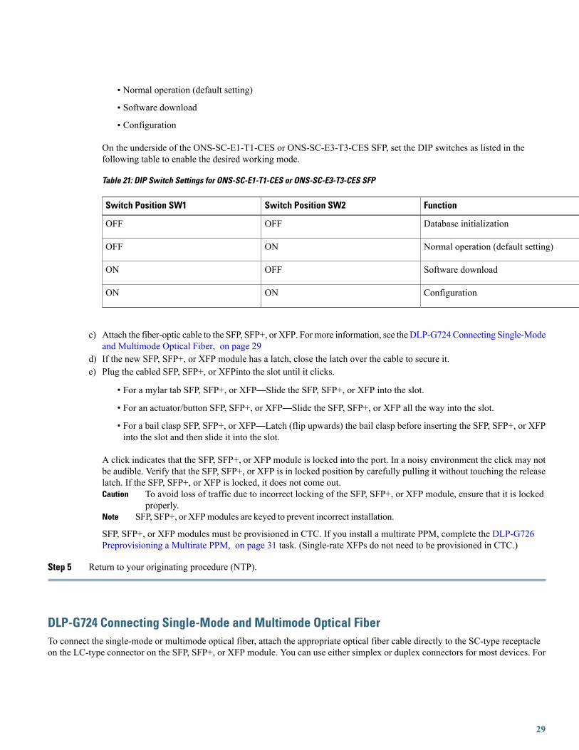
• Normal operation (default setting)
• Software download
• Configuration
On the underside of the ONS-SC-E1-T1-CES or ONS-SC-E3-T3-CES SFP, set the DIP switches as listed in thefollowing table to enable the desired working mode.
Table 21: DIP Switch Settings for ONS-SC-E1-T1-CES or ONS-SC-E3-T3-CES SFP
FunctionSwitch Position SW2Switch Position SW1
Database initializationOFFOFF
Normal operation (default setting)ONOFF
Software downloadOFFON
ConfigurationONON
c) Attach the fiber-optic cable to the SFP, SFP+, or XFP. For more information, see the DLP-G724 Connecting Single-Modeand Multimode Optical Fiber, on page 29
d) If the new SFP, SFP+, or XFP module has a latch, close the latch over the cable to secure it.e) Plug the cabled SFP, SFP+, or XFPinto the slot until it clicks.
• For a mylar tab SFP, SFP+, or XFP—Slide the SFP, SFP+, or XFP into the slot.
• For an actuator/button SFP, SFP+, or XFP—Slide the SFP, SFP+, or XFP all the way into the slot.
• For a bail clasp SFP, SFP+, or XFP—Latch (flip upwards) the bail clasp before inserting the SFP, SFP+, or XFPinto the slot and then slide it into the slot.
A click indicates that the SFP, SFP+, or XFP module is locked into the port. In a noisy environment the click may notbe audible. Verify that the SFP, SFP+, or XFP is in locked position by carefully pulling it without touching the releaselatch. If the SFP, SFP+, or XFP is locked, it does not come out.
To avoid loss of traffic due to incorrect locking of the SFP, SFP+, or XFP module, ensure that it is lockedproperly.
Caution
SFP, SFP+, or XFPmodules are keyed to prevent incorrect installation.Note
SFP, SFP+, or XFP modules must be provisioned in CTC. If you install a multirate PPM, complete the DLP-G726Preprovisioning a Multirate PPM, on page 31 task. (Single-rate XFPs do not need to be provisioned in CTC.)
Step 5 Return to your originating procedure (NTP).
DLP-G724 Connecting Single-Mode and Multimode Optical FiberTo connect the single-mode or multimode optical fiber, attach the appropriate optical fiber cable directly to the SC-type receptacleon the LC-type connector on the SFP, SFP+, or XFP module. You can use either simplex or duplex connectors for most devices. For
29

simplex connectors, two cables are required, one cable for transmit (Tx) and a second cable for receive (Rx). For duplex connectors,only one cable that has both Tx and Rx connectors is required.
This task connects the single-mode or multimode optical fiber for SFP, SFP+, and XFPmodules installed on the line cards.
Purpose
NoneTools/Equipment
NonePrerequisite Procedures
As neededRequired/As Needed
OnsiteOnsite/Remote
Provisioning or higherSecurity Level
Procedure
Step 1 Remove the protective plugs from the SFP, SFP+, and XFP module and save them for future use.Step 2 Remove the protective caps from the connectors on the fiber-optic cable and save them for future use.Step 3 Clean fiber-optic connectors on fiber-optic cables.Step 4 Plug the fiber-optic cable into the SC-type receptacle on the LC-type connector on the SFP, SFP+, or XFP module.Step 5 Return to your originating procedure (NTP).
DLP-G725 Preprovisioning PPM Slot
This task preprovisions PPM (SFP, SFP+, or XFP) slot.Purpose
NoneTools/Equipment
"NTP-J22 Log into CTC" task in the chapter "Understanding the Carrier Packet TransportSystem" of Cisco CPT Configuration Guide.
Prerequisite Procedures
As neededRequired/As Needed
Onsite or remoteOnsite/Remote
Provisioning or higherSecurity Level
30

SFP, SFP+, and XFP modules are generically called PPMs in CTC. After installing multirate SFP, SFP+,and XFP modules, multirate PPMs must be provisioned in CTC. To complete the provisioning of themultirate pluggable port, complete the DLP-G726 Preprovisioning a Multirate PPM, on page 31 task.
Note
Procedure
Step 1 In node view (single-shelf mode) or shelf view (multishelf mode), double-click the card where you want to provision PPMsettings.
Step 2 Click the Provisioning > Pluggable Port Modules tabs.Step 3 In the Pluggable Port Modules area, click Create. The Create PPM dialog box appears.Step 4 In the Create PPM dialog box, complete the following:
• PPM—Choose the slot number where the SFP, SFP+, or XFP module is installed, from the drop-down list.
• PPM Type—Choose the number of ports supported by your SFP, SFP+, or XFP module, from the drop-down list.The drop-down list displays the number of PPMs that are available for provisioning. If only one port is supported,PPM (1 port) is the only option.
Step 5 Click OK. The newly created port appears in the Pluggable Port Modules pane. The row in the Pluggable Port Modulespane turns light blue. The Actual Equipment Type column remains blank until the actual SFP, SFP+, or XFP module isinstalled. After the SFP, SFP+, or XFP module is installed, the row in the pane turns white and the Actual Equipment Typecolumn shows the equipment name.
For ONS-SC-E1-T1-CES and ONS-SC-E3-T3-CES SFPs, set the port rate asFE.
Note
Step 6 Verify that the PPM appears in the list in the Pluggable Port Modules pane. If it does not, repeat Step Step 3 throughStep Step 5.
Step 7 Repeat Step Step 2 through Step Step 5 to provision a second PPM, if needed. If not, continue with Step Step 8.Step 8 Click OK.Step 9 Return to your originating procedure (NTP).
DLP-G726 Preprovisioning a Multirate PPM
This task provisions a multirate PPM on a line card.Purpose
NoneTools/Equipment
"NTP-J22 Log into CTC" task in the chapter "Understanding the Carrier Packet TransportSystem" of Cisco CPT Configuration Guide.
Prerequisite Procedures
As neededRequired/As Needed
Onsite or remoteOnsite/Remote
31

Provisioning or higherSecurity Level
If the PPM was preprovisioned using the DLP-G725 Preprovisioning PPM Slot, on page 30 task, thistask is unnecessary.
Note
Procedure
Step 1 In node view (single-shelf mode) or shelf view (multishelf view), double-click the line card where you want to provisionthe multirate PPM settings.
Step 2 If this is the first multirate PPM provisioned for the card, continue with Step 3. If not, complete the following steps.a) Click the Provisioning > Line > SONET (ANSI) or SDH (ETSI) tabs.b) Locate the Trunk port table row and verify that the Service State column value is OOS-MA,DSBLD (ANSI) or
Locked-enabled,disabled (ETSI). If yes, continue with Step 3. If not, continue with the following step.c) Click the Admin State table cell and choose OOS-MA,DSBLD (ANSI) or Locked-enabled,disabled.d) Click Apply, then Yes.
Step 3 Click the Provisioning > Pluggable Port Modules tabs.Step 4 In the Pluggable Port Modules area, click Create. The Create PPM dialog box appears.Step 5 In the Create PPM dialog box, complete the following:
• PPM—Choose the slot number where the multirate PPM is installed, from the drop-down list.
• PPM Type—Choose the number of ports supported by your multirate PPM from the drop-down list. If only one portis supported, PPM (1 port) is the only option.
Step 6 Click OK. The newly created port appears in the Pluggable Port Modules area. The row in the Pluggable Port Modulesarea turns white and the Actual Equipment Type column lists the equipment name.
Step 7 If you want to provision a PPM on another port, repeat Step 3 through Step Step 5.Step 8 Return to your originating procedure (NTP).
DLP-G727 Delete PPM Provisioning
This task deletes PPM provisioning for SFP, SFP+, and XFP modules installed on the linecards.
Purpose
NoneTools/Equipment
"NTP-J22 Log into CTC" task in the chapter "Understanding the Carrier Packet TransportSystem" of Cisco CPT Configuration Guide.
Prerequisite Procedures
As neededRequired/As Needed
32

Onsite or remoteOnsite/Remote
Provisioning or higherSecurity Level
Procedure
Step 1 In node view (single-shelf mode) or shelf view (multishelf view), double-click the line card where you want to delete PPMsettings.
Step 2 Verify that the PPM port Service State is OOS,DSBLD.Step 3 Click the Provisioning > Pluggable Port Modules tabs.Step 4 To delete a PPM and the associated ports, perform the following:
a) In the Pluggable Port Modules area, click the PPM that you want to delete. The highlight changes to dark blue.b) Click Delete. The Delete PPM dialog box appears.c) Click Yes. The PPM provisioning is removed from the Pluggable Port Modules area and the Pluggable Ports area.
You cannot delete a PPM until its port is in the OOS,DSBLD state. You cannot delete a client port if the clientis in the In Service and Normal (IS-NR) service state, is in a protection group, has a generic communicationschannel (GCC) or data communications channel (DCC), is a timing source, has circuits or overhead circuits,or transports Link Management Protocol channels or links. You can delete a client port (except the last port)if the trunk port is in service and the client port is in the OOS,DSBLD service state. You can delete the lastclient port only if the trunk port is in a OOS,DSBLD (ANSI) service state for all the cards. For more informationabout port states, see the Administrative and Service States document.
Note
Step 5 Verify that the PPM provisioning is deleted:
• In the card view, CTC shows an empty port after the PPM is deleted.
• If the PPM is physically present when you delete the PPM provisioning, CTC transitions to the deleted state, theports (if any) are deleted, and the PPM is represented as a gray graphic in CTC. The PPM can be provisioned againin CTC, or the equipment can be removed. If the equipment is removed, the graphic disappears.
Step 6 (Optional) If you need to remove the PPM hardware, complete the DLP-G728 Remove PPM from the Line Card, on page33.
Step 7 Return to your originating procedure (NTP).
DLP-G728 Remove PPM from the Line Card
This task removes PPMs from the line cards.Purpose
33
•Wrist strap or other personal grounding device to prevent electro-static discharge(ESD) occurrences.
• Antistatic mat or antistatic foam to set the PPM on.
• Fiber-optic end-face cleaning tools and inspection equipment. For complete informationon inspecting and cleaning fiber-optic connections, see the Inspection and CleaningProcedures for Fiber-Optic Connections document.
Tools/Equipment
NonePrerequisite Procedures
As neededRequired/As Needed
OnsiteOnsite/Remote
Provisioning or higherSecurity Level
SFP, SFP+, and XFP modules are Class I laser products. Statement 1008Warning
Because invisible laser radiation may be emitted from the aperture of the port when no cable is connected,avoid exposure to laser radiation and do not stare into open apertures. Statement 70
Warning
Ultimate disposal of this product should be handled according to all national laws and regulations. Statement1040
Warning
Note • This task removes the SFP, SFP+, and XFP hardware. To delete the provisioning for SFP, SFP+,and XFP, see the DLP-G727 Delete PPM Provisioning, on page 32 task.
Procedure
Step 1 Disconnect the network fiber cable from the PPM connector. If the SFP, SFP+, and XFP connector has a latch securingthe fiber cable, pull it upward to release the cable.
Step 2 Remove PPM. Perform the following as necessary:
• To remove SFP, SFP+, or XFP module, go to Step Step 5.
Step 3 Remove SFP, SFP+, or XFP module. Perform the following:a) If the SFP, SFP+, or XFP connector has a latch securing the fiber cable, pull it upward to release the cable.b) Pull the fiber cable straight out of the connector.
34

c) Release the SFP, SFP+, or XFP module from the slot by performing one of the following actions (depending on whichlatch is on the SFP, SFP+, or XFP):
• For a mylar tab SFP, SFP+, or XFP—Pull out the mylar tab.
• For an actuator/button SFP, SFP+, or XFP—Press the actuator/button.
• For a bail clasp SFP, SFP+, or XFP—Unlatch the bail clasp and swing it downward.
d) Slide the SFP, SFP+, or XFP module out of the slot.
Step 4 Return to your originating procedure (NTP).
Related DocumentationUse this document in conjunction with the following referenced publications as needed:
• Cisco CPT Configuration Guide
• Cisco CPT Command Reference Guide
• Regulatory Compliance and Safety Information for Cisco CPT and Cisco ONS Platforms
Obtaining Documentation and Submitting a Service RequestFor information on obtaining documentation, using the Cisco Bug Search Tool (BST), submitting a service request, and gatheringadditional information, seeWhat's New in Cisco Product Documentation, at: http://www.cisco.com/c/en/us/td/docs/general/whatsnew/whatsnew.html.
Subscribe toWhat's New in Cisco Product Documentation, which lists all new and revised Cisco technical documentation as an RSSfeed and delivers content directly to your desktop using a reader application. The RSS feeds are a free service.
35

© 2014 Cisco Systems, Inc. All rights reserved.

Europe HeadquartersAsia Pacific HeadquartersAmericas HeadquartersCisco Systems International BVAmsterdam, The Netherlands
Cisco Systems (USA) Pte. Ltd.Singapore
Cisco Systems, Inc.San Jose, CA 95134-1706USA
Cisco has more than 200 offices worldwide. Addresses, phone numbers, and fax numbers are listed on theCisco Website at www.cisco.com/go/offices.


