Institute of Southern Punjab, Multan Mr. Muhammad Nouman Farooq BSC-H (Computer Science) MS (Telecomm. and Networks) Honors: Magna Cumm Laude Honors Degree Gold Medalist! Blog Url: noumanfarooqatisp.wordpress.com E-Mail: [email protected]
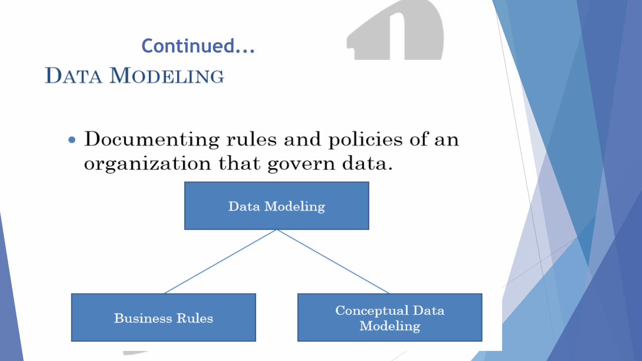
Database Modeling follows the analysis phase. Documenting
rules and policies of an organization that govern data and
implementing them into a design which is an Entity
Relationship Diagram (ERD).
1. Business Rule
2. Conceptual Data Modeling
5
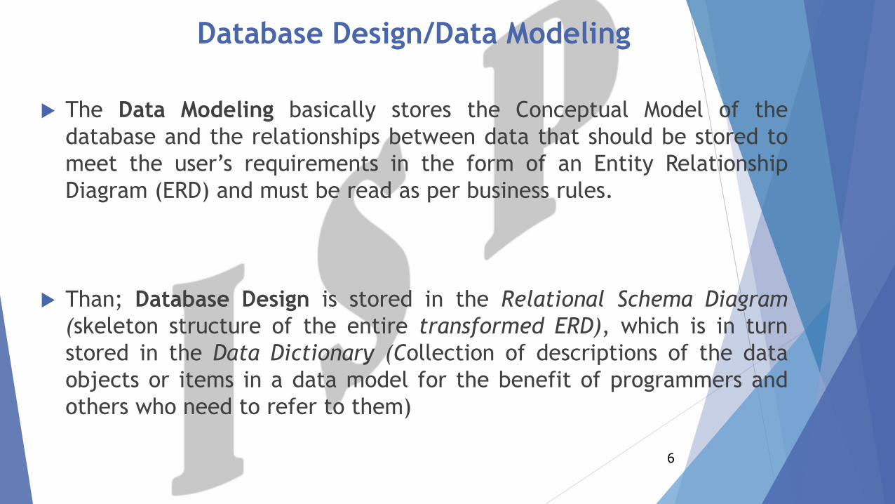
Database Design/Data Modeling
The Data Modeling basically stores the Conceptual Model of the
database and the relationships between data that should be stored to
meet the user’s requirements in the form of an Entity Relationship
Diagram (ERD) and must be read as per business rules.
Than; Database Design is stored in the Relational Schema Diagram
(skeleton structure of the entire transformed ERD), which is in turn
stored in the Data Dictionary (Collection of descriptions of the data
objects or items in a data model for the benefit of programmers and
others who need to refer to them)
6
Continued...
7
Top-Down Approach: -
Design by Analysis
Only Database Administrator’s can firstly design thestructure of the database (makes an ERD in Conceptual Data ModelingPhase) and than transforms it into Relations in Logical Data ModelingPhase and than afterwards code that structure of transformed ERD inImplementation Phase using a DBMS (MySQL in XAMPP) making aDatabase System; This approach is termed as Design by Analysis. A gooddesign must reduces duplication of data, reduces anomalies in data, wemust makes it in 3rd Normal Form (3-NF) for commercial applications.
In Physical Design phase; It requires a knowledge ofthe specific DBMS that will be used to implement the database (datatypes, triggers, indexes etc).
Bottom-Up Approach: -
Design by Synthesis
Database Modeling
It is a very important process because the designing of the
application provides us the basis for running our database system.
If the database is not designed properly, the implementation of the
system can not be done properly.
Generally, the design of the database is represented graphically
because it provides an ease in design and adds flexibility for the
understanding of the system easily.
8
Continued...
9
10
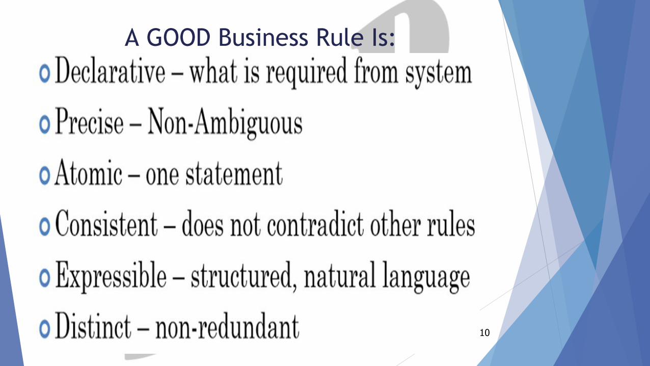
A GOOD Business Rule Is:
Business Rules
11
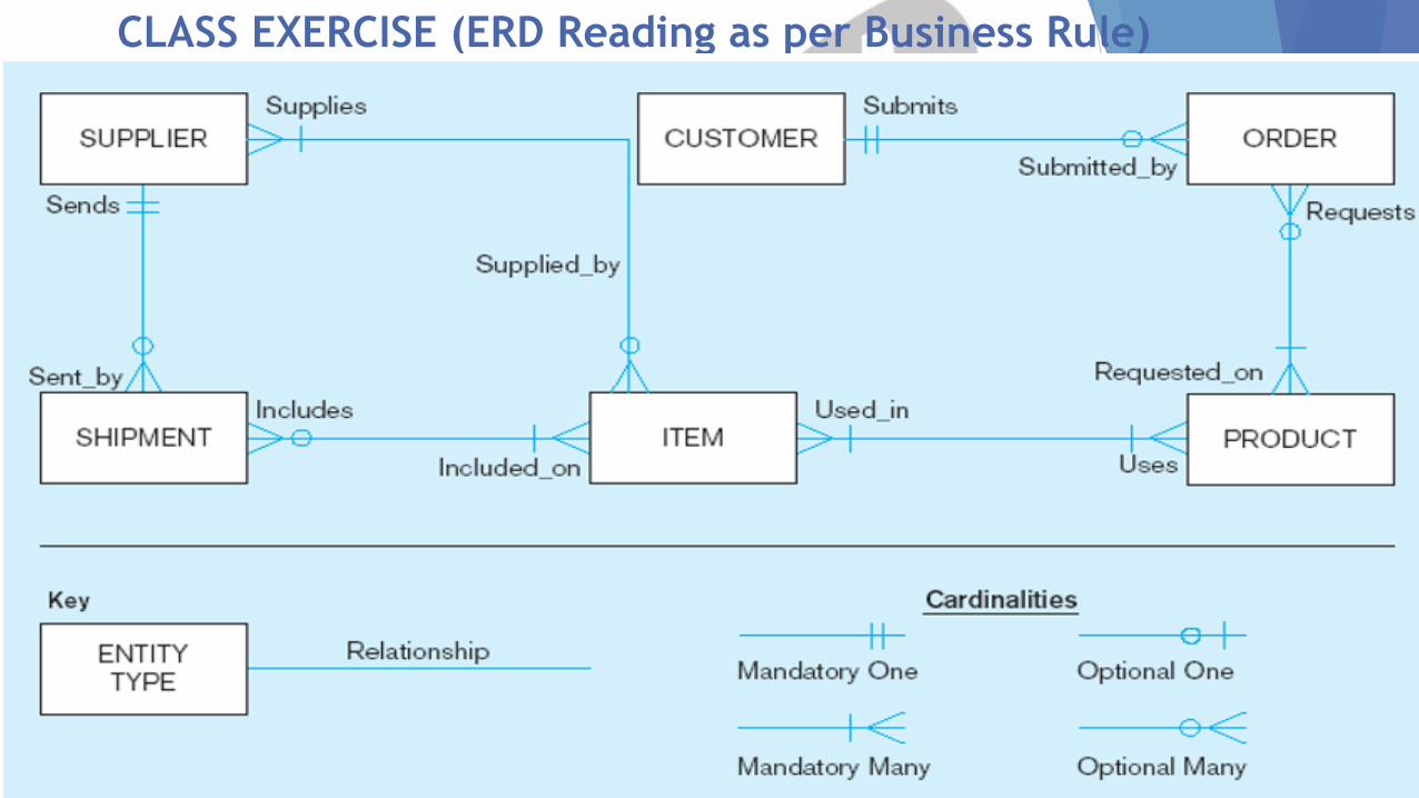
CLASS EXERCISE (ERD Reading as per Business Rule)
12
SOLUTION OF CLASS EXCERCISE
13
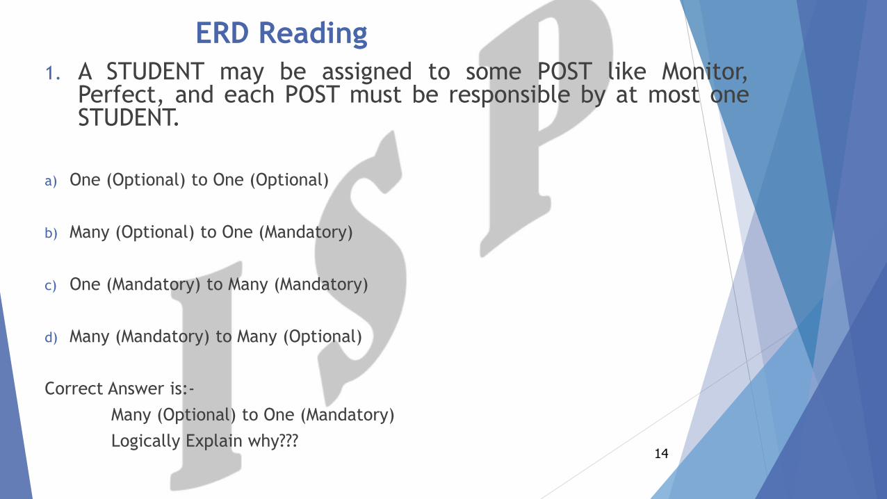
ERD Reading
1. A STUDENT may be assigned to some POST like Monitor,Perfect, and each POST must be responsible by at most oneSTUDENT.
a) One (Optional) to One (Optional)
b) Many (Optional) to One (Mandatory)
c) One (Mandatory) to Many (Mandatory)
d) Many (Mandatory) to Many (Optional)
Correct Answer is:-
Many (Optional) to One (Mandatory)
Logically Explain why???14
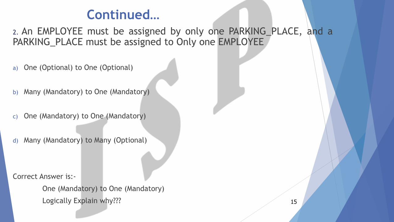
Continued…2. An EMPLOYEE must be assigned by only one PARKING_PLACE, and aPARKING_PLACE must be assigned to Only one EMPLOYEE
a) One (Optional) to One (Optional)
b) Many (Mandatory) to One (Mandatory)
c) One (Mandatory) to One (Mandatory)
d) Many (Mandatory) to Many (Optional)
Correct Answer is:-
One (Mandatory) to One (Mandatory)
Logically Explain why??? 15
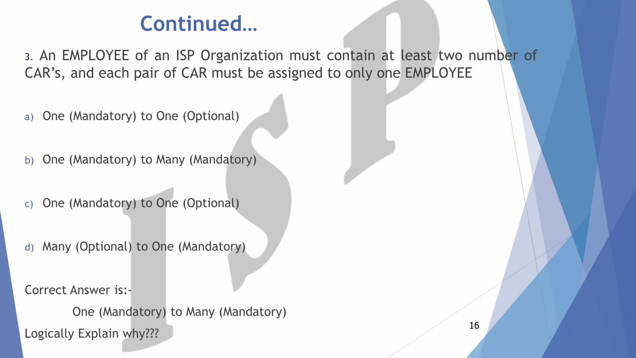
Continued…
3. An EMPLOYEE of an ISP Organization must contain at least two number of
CAR’s, and each pair of CAR must be assigned to only one EMPLOYEE
a) One (Mandatory) to One (Optional)
b) One (Mandatory) to Many (Mandatory)
c) One (Mandatory) to One (Optional)
d) Many (Optional) to One (Mandatory)
Correct Answer is:-
One (Mandatory) to Many (Mandatory)
Logically Explain why???16
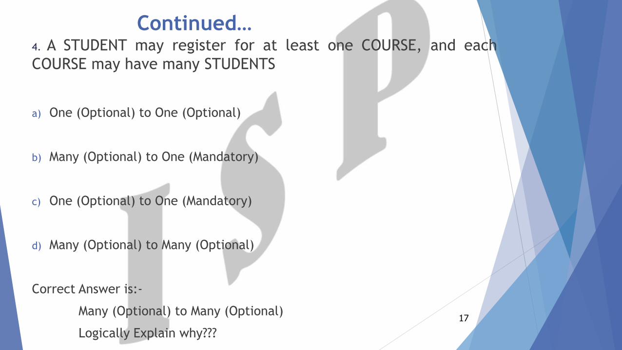
Continued…4. A STUDENT may register for at least one COURSE, and each
COURSE may have many STUDENTS
a) One (Optional) to One (Optional)
b) Many (Optional) to One (Mandatory)
c) One (Optional) to One (Mandatory)
d) Many (Optional) to Many (Optional)
Correct Answer is:-
Many (Optional) to Many (Optional)
Logically Explain why???
17
Entity Relationship Diagram (ERD)
18
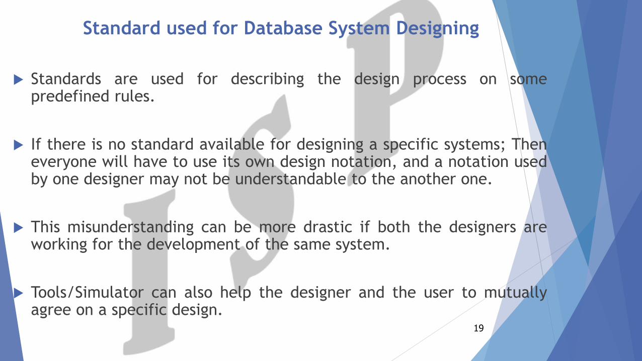
Standard used for Database System Designing
Standards are used for describing the design process on somepredefined rules.
If there is no standard available for designing a specific systems; Theneveryone will have to use its own design notation, and a notation usedby one designer may not be understandable to the another one.
This misunderstanding can be more drastic if both the designers areworking for the development of the same system.
Tools/Simulator can also help the designer and the user to mutuallyagree on a specific design.
19
Continued…
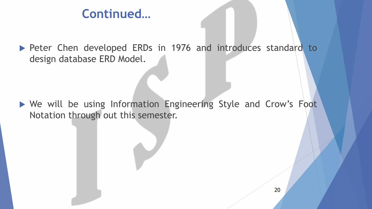
Peter Chen developed ERDs in 1976 and introduces standard to
design database ERD Model.
We will be using Information Engineering Style and Crow’s Foot
Notation through out this semester.
20
E-R Model Constructs
21
Components of ER Diagram
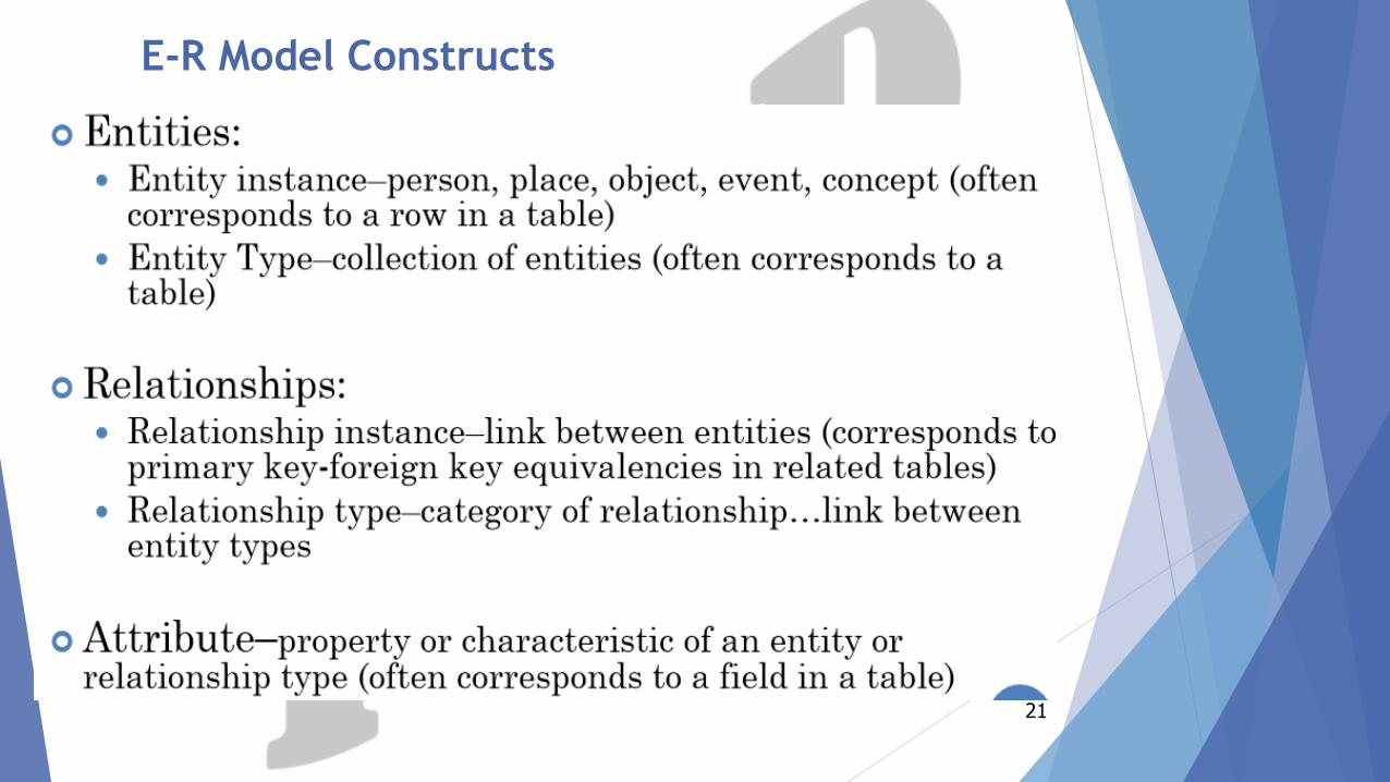
The ER data model supports following major constructs:
1. The Entity
2. Attribute
3. Relationship
22
The Entity
Entity is basic building block of the ER data model.
The term entity is used in three different meanings or for three
different terms and that are:
1. Entity Type
2. Entity Instance
3. Entity Set
23
Entity Type
Anything that receives or generates data from or to the system is an entity.
Entity Type is transformed into a Table in any DBMS engine.
They are typically singular nouns, e.g. customer, supervisor, location orpromotion.
Entity type is name assigned to a collection of properties of differentthings existing in an environment.
24
Continued…
Generally, the entity types and their properties are established by
nature, by very existence of the things.
For example, a bulb is an electric accessory, a cricket bat is a sports
item, a computer is an electronic device, a shirt is a clothing item
etc.
25
Classification Of Entity Types
Entity types (ETs) can be classified into regular ETs or weak ETs.
Regular ETs are also called strong or independent ETs, whereas weak
ETs are also called dependent ETs.
26
Weak Entity Types
It depend on some other entity type and have no meaning in the diagram
without depending on another entity.
Example: Course (Course cannot be taught without teacher)
An entity type whose instances cannot exist without being linked with
instances of some other entity type, i.e., they cannot exist independently.
For example, in an organization we want to maintain data about the
vehicles owned by the employees.
Now, a particular vehicle can exist in this organization only if the owner
already exists there as employee.
27
Continued…
Similarly, if employee leaves the job and the organization decides to
delete the record of the employee then the record of the vehicle will
also be deleted.
Since, Entity cannot exist without being linked to an instance of
employee. This type of entity is called as weak entity or dependent
entity.
28
Strong Entity Types
An entity type whose instances can exist independently, that is,
without being linked to the instances of any other entity type is
called strong or regular entity type.
A major property of the strong entity types is that they have their
own identification, which is not always the case with weak entity
types.
For example, employee in the previous example is an independent or
strong entity type, since its instances can exist independently.
29
Entity Instance
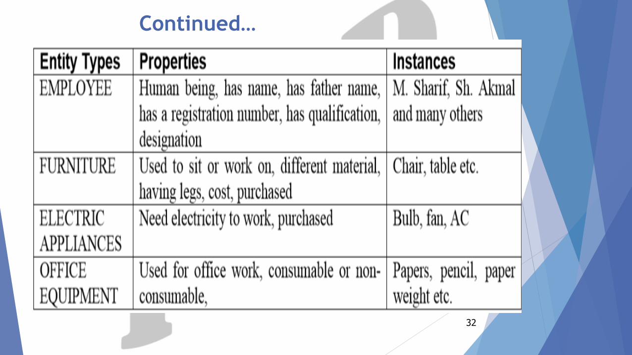
Each entity instance possesses certain values against the properties withthe entity type to which it belongs.
For example, In the given table on next slide; we have identified thatentity type EMPLOYEE has name, father name, registration number,qualification, designation.
Now, an instance of this entity type will have values against each of theseproperties, like (M. Sajjad, Abdul Rehman, EN-14289, BCS, andProgrammer) may be one instance of entity type EMPLOYEE. There couldbe many others.
Entity Instance is termed as Rows/Tuples or Records in any DBMS engine.
30
Continued…
The entity instance can be defined as a name/label assigned to
items/objects that exist in an environment and that have similar
properties.
31
Continued…
32
Entity Set
A group of entity instances of a particular entity type is called an
entity set.
For example, all employees of an organization form an entity set.
Like all students, all courses, all of them form entity set of different
entity types.
33
Naming Entity Types
Following are some recommendations for naming entity types.
Good Designs usually follow these practices:
1. Singular Noun Recommended
2. Organization specific names, like CUSTOMER, CLIENT
3. Write in Capitals
4. Abbreviations can be used, be consistent. Avoid using confusingabbreviations.
34
Symbols for Entity Types
A rectangle is used to represent an entity type in ER data model.
For strong entity types rectangle with a single line is used whereas
double lined rectangle is drawn to represent a weak entity type as is
shown below:
35
Attribute
Attributes are characteristics of an entity in a relationship.
Attributes are termed as a Columns/Fields in any DBMS engine.
An attribute of an entity is a defining property of that entity type.
Entity instances of entity type STUDENT have attributes like
stdRegNo, stdName etc.
36
Continued…
However, values of these attributes may be same or different. For
example, all instances of the entity type STUDENT may have the
attributes stdName, stdFatherName, stdAge; but the values against
each of these attributes for each instance must be different in most
of the cases.
An attribute is identified by a name allocated to it and that has to
be unique with respect to that entity type. It means one entity type
cannot have two attributes with the same name.
However, different entity types may have attributes with the same
name. 37
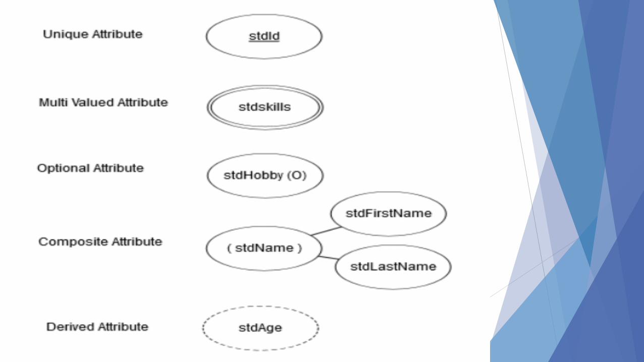
Continued…
Standard of writing Attributes is:
1. The notation that has been adopted in this course as a Standardis that attribute name generally consists of two parts. The nameis started in lower case, and usually consists of abbreviation ofthe entity types to which the attribute belongs.
2. Second part of the attribute name describes the purpose ofattribute and only first letter is capital.
For example employeeName means name attribute of entity typeEMPLOYEE, stdAddress means address attribute of the entity typeSTUDENT.
38
Domain of an Attribute
As every Attribute has got a name.
Next thing is that a domain is also associated with an
attribute. These two things, name and the domain, are
important part of an attribute.
Domain is a form of a check on attribute that it cannot have a
value outside of this set.
Domain is known as Data Type in Physical Design (DS)
39
Continued…
Associating domain with an attribute helps in maintaining the
integrity of the database, Since only legal values could be
assigned to an attribute.
Legal values mean the values that an attribute can have in an
environment or system. For example, if we define a salary
attribute of EMPLOYEE entity type to hold the salary of
employees, the value assigned to this attribute should be
numeric, it should not be assigned a value like date
‘10/10/2004’, because they are not legal salary values. But, It
must be numeric.
40
Continued…
Not only specify that the value of salary will be numeric but also
associated with a range, a lower and upper limit. It reduces the
chances of mistake.
Domain is normally defined in form of data type and some
additional constraints like the range constraint.
Data type is defined as a set of values along with the operations
that can be performed on those values. Some common data
types are Integer, Float, AutoNumber, Date/Time, Currency etc.
41
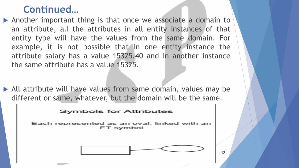
Continued… Another important thing is that once we associate a domain to
an attribute, all the attributes in all entity instances of that
entity type will have the values from the same domain. For
example, it is not possible that in one entity instance the
attribute salary has a value 15325.40 and in another instance
the same attribute has a value 15325.
All attribute will have values from same domain, values may be
different or same, whatever, but the domain will be the same.
42
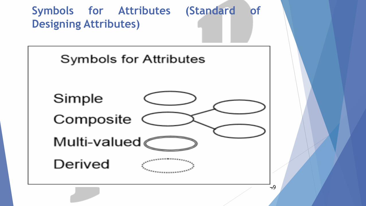
Types of Attributes
Attributes may be of different types. They may be:
1. Simple or Composite
2. Single Valued or Multi-Valued
3. Stored or Derived
4. Key or Non-Key
5. Required or Optional
43
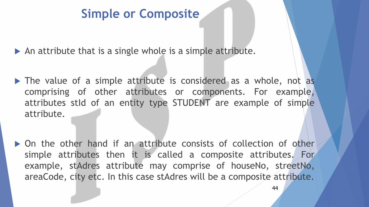
Simple or Composite
An attribute that is a single whole is a simple attribute.
The value of a simple attribute is considered as a whole, not as
comprising of other attributes or components. For example,
attributes stId of an entity type STUDENT are example of simple
attribute.
On the other hand if an attribute consists of collection of other
simple attributes then it is called a composite attributes. For
example, stAdres attribute may comprise of houseNo, streetNo,
areaCode, city etc. In this case stAdres will be a composite attribute.44
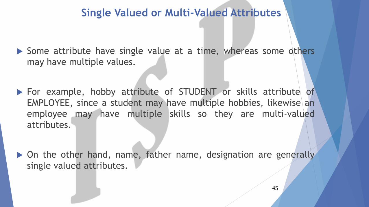
Single Valued or Multi-Valued Attributes
Some attribute have single value at a time, whereas some others
may have multiple values.
For example, hobby attribute of STUDENT or skills attribute of
EMPLOYEE, since a student may have multiple hobbies, likewise an
employee may have multiple skills so they are multi-valued
attributes.
On the other hand, name, father name, designation are generally
single valued attributes.
45
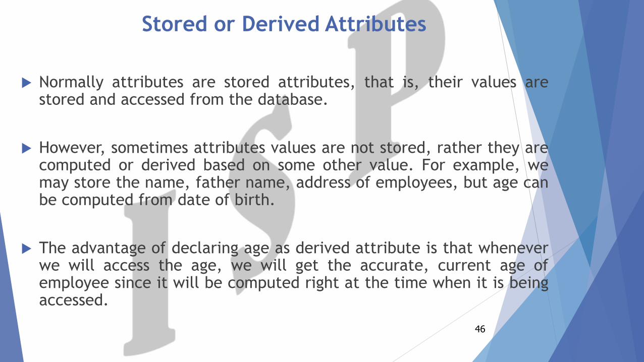
Stored or Derived Attributes
Normally attributes are stored attributes, that is, their values arestored and accessed from the database.
However, sometimes attributes values are not stored, rather they arecomputed or derived based on some other value. For example, wemay store the name, father name, address of employees, but age canbe computed from date of birth.
The advantage of declaring age as derived attribute is that wheneverwe will access the age, we will get the accurate, current age ofemployee since it will be computed right at the time when it is beingaccessed.
46
Class Activity (Classify the following Attributes)
1. empFirstName
2. empLastName
3. empIdNo
4. empHobbies
5. empPassword
47
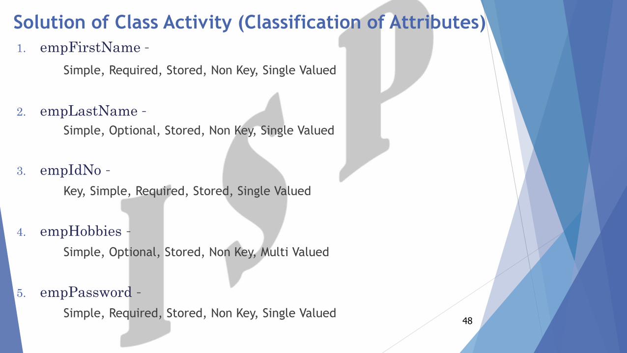
Solution of Class Activity (Classification of Attributes)
1. empFirstName –
Simple, Required, Stored, Non Key, Single Valued
2. empLastName –
Simple, Optional, Stored, Non Key, Single Valued
3. empIdNo –
Key, Simple, Required, Stored, Single Valued
4. empHobbies –
Simple, Optional, Stored, Non Key, Multi Valued
5. empPassword –
Simple, Required, Stored, Non Key, Single Valued48
Symbols for Attributes (Standard of
Designing Attributes)
49
50
Relationships
Relationships, which represent the link between different entities.
Each relationship has a Name.
Each relationship has a Cardinality (Optional or Mandatory)
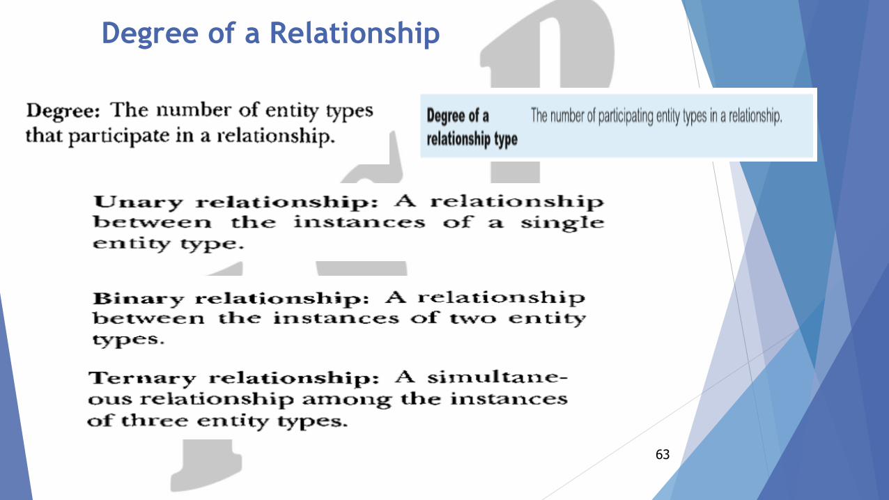
Each relationship has a Degree (how many entity types which are
participating in a relationship for example Unary, Binary and ternary)
Each relationship has a type (One-to-One, One-to-Many and Many-to-
Many).
51
Symbol for Relationships
1. Shown as a Diamond.
2. Diamond is doubled if one of the participant is dependent on the other.
3. Participants are connected by continuous lines, labeled to indicatecardinality.
4. In partial relationships role, It is written on the line connecting thepartially participating entity rectangle to the relationship diamond.
5. Total participation is indicated by double lines.
52
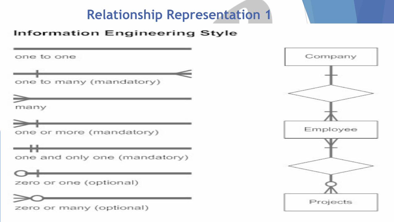
Relationship Representation 1
53
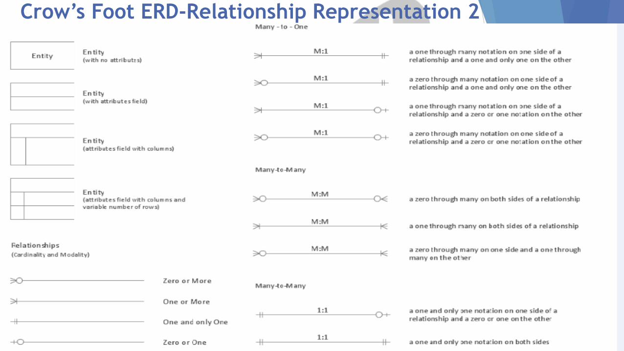
Crow’s Foot ERD-Relationship Representation 2
54
Naming Relationships
Entities enrolled in a relationship are called its Participants.
If there is no proper name of the association in the system then
participant’s names abbreviations are used.
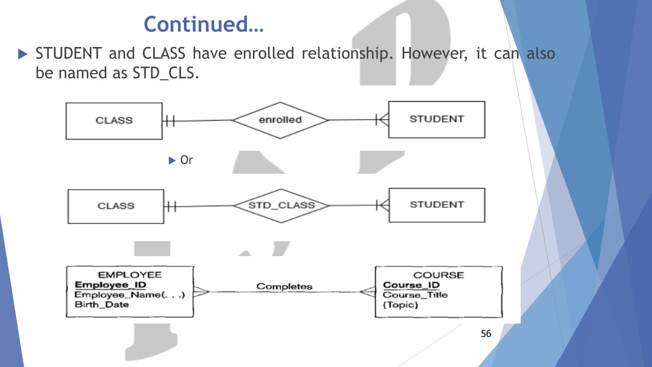
STUDENT and CLASS have enrolled relationship. However, it can also
be named as STD_CLS.
55
STUDENT and CLASS have enrolled relationship. However, it can also
be named as STD_CLS.
56
Continued…
Or
57
Relationships Instances
Types of Relationships
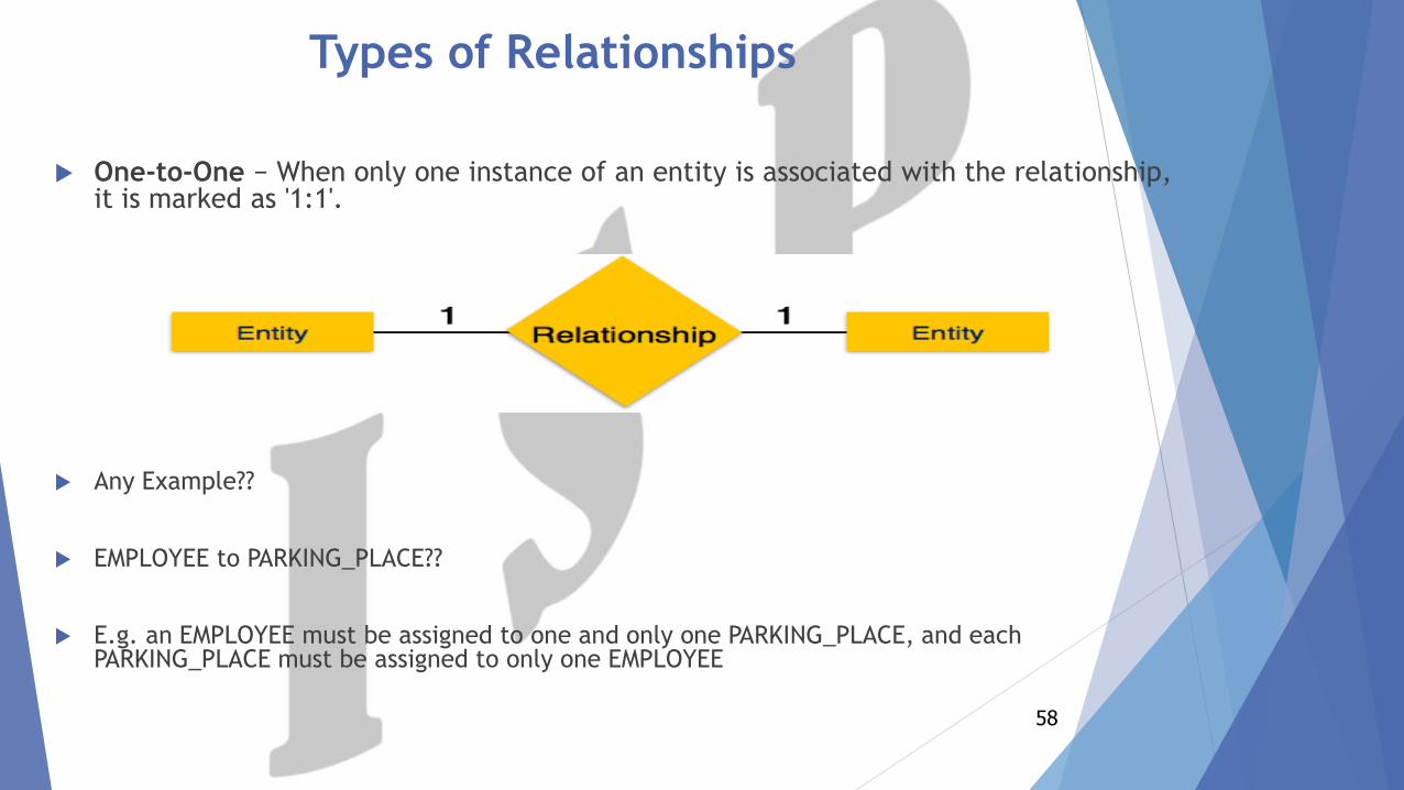
One-to-One − When only one instance of an entity is associated with the relationship, it is marked as '1:1'.
Any Example??
EMPLOYEE to PARKING_PLACE??
E.g. an EMPLOYEE must be assigned to one and only one PARKING_PLACE, and each PARKING_PLACE must be assigned to only one EMPLOYEE
58
Continued…
One-to-Many- When more than one instance of an entity is associated with a
relationship, it is marked as '1:N'.
Any Example??
TEACHER to STUDENT Relationship??
E.g. TEACHER must teaches at least five number of STUDENT. STUDENT must be
taught by at most one TEACHER
59
Continued…
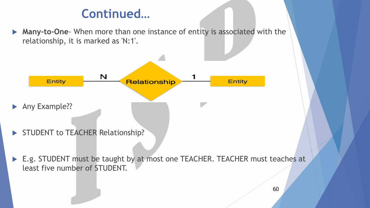
Many-to-One- When more than one instance of entity is associated with the
relationship, it is marked as 'N:1'.
Any Example??
STUDENT to TEACHER Relationship?
E.g. STUDENT must be taught by at most one TEACHER. TEACHER must teaches at
least five number of STUDENT.
60
Continued…
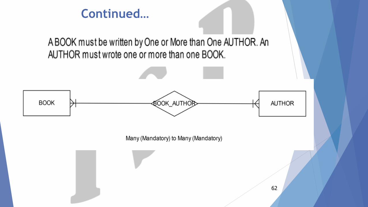
Many-to-Many- The following image reflects that more than one instance of an entity on the left and more than one instance of an entity on the right can be associated with the relationship.
Any Example???
STUDENT to COURSE Relationship??
E.g. STUDENT may completes one or more than one COURSE, and each COURSE may be completed by many number of STUDENT
61
Continued…
62
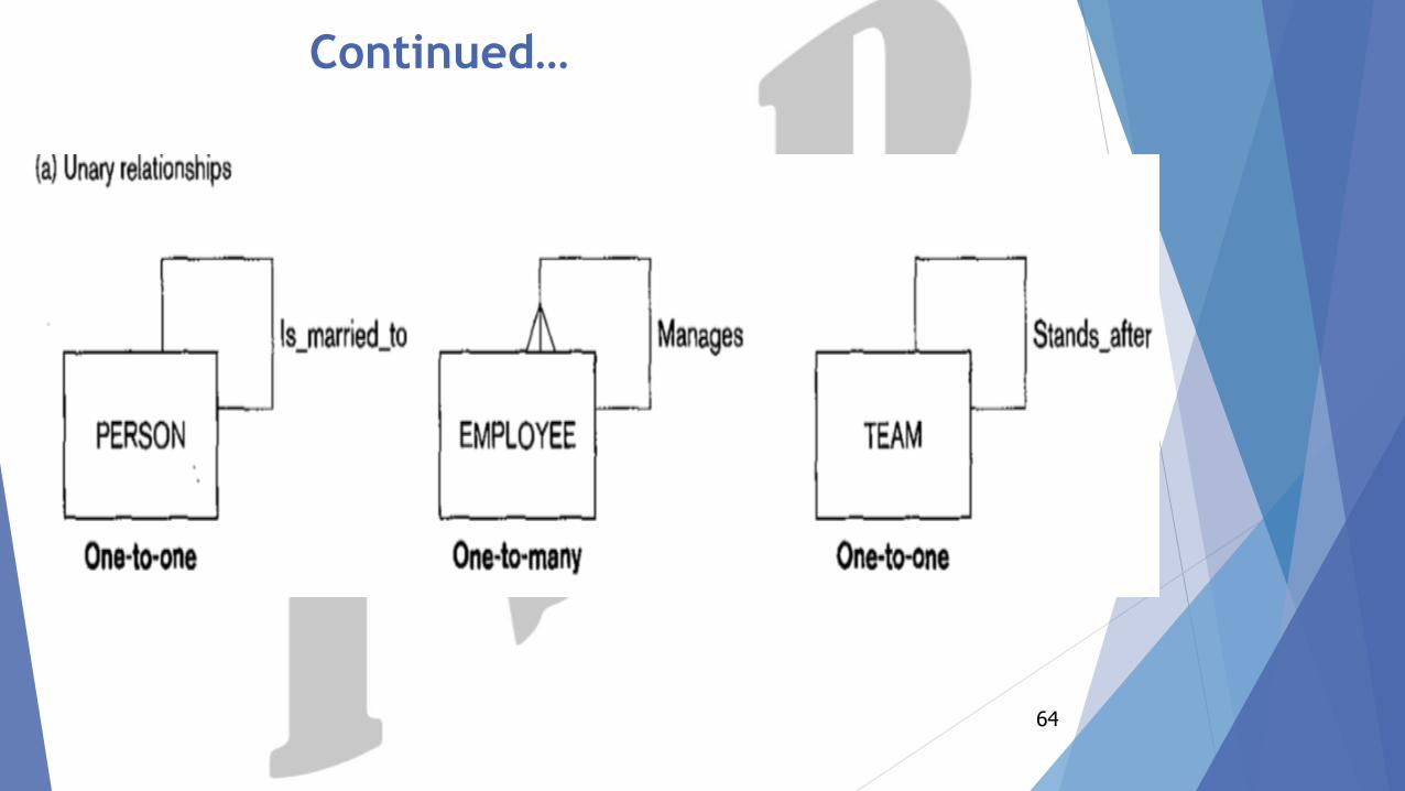
Degree of a Relationship
63
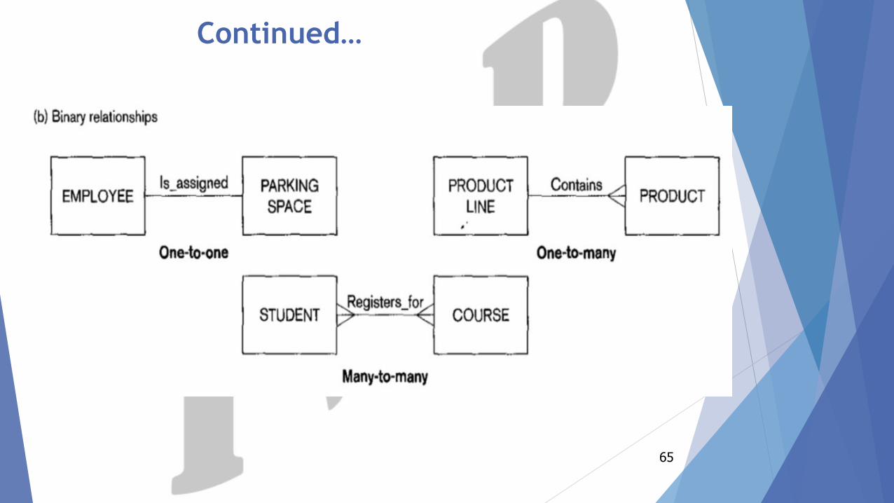
Continued…
64
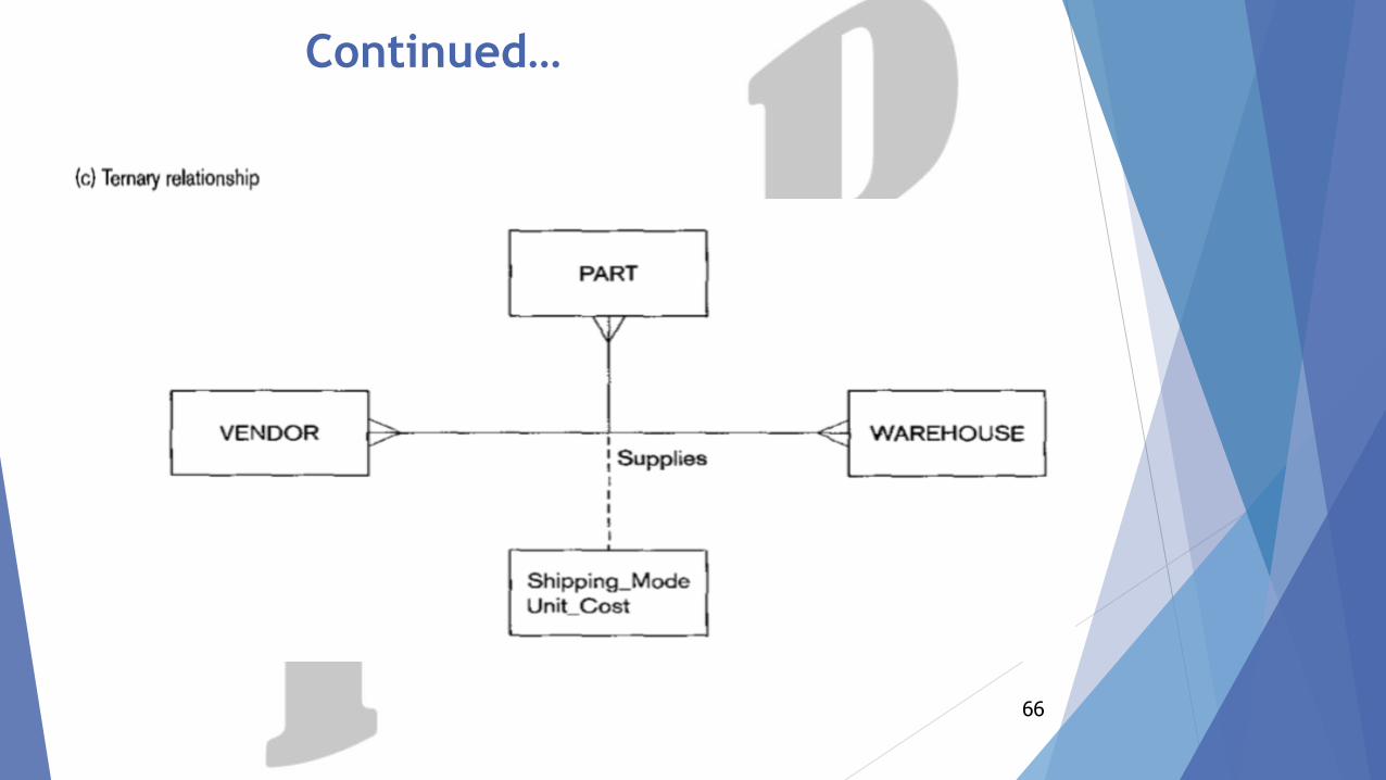
Continued…
65
Continued…
66
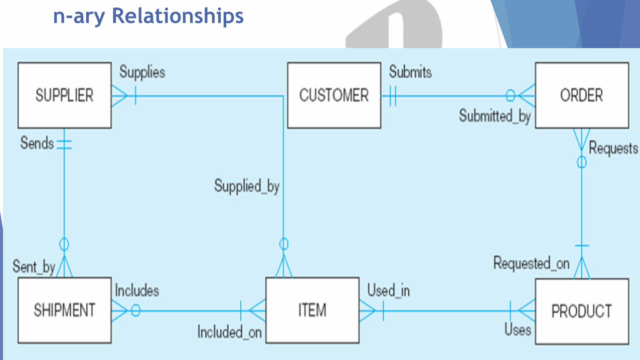
n-ary Relationships
67
Cardinality of Relationship
68
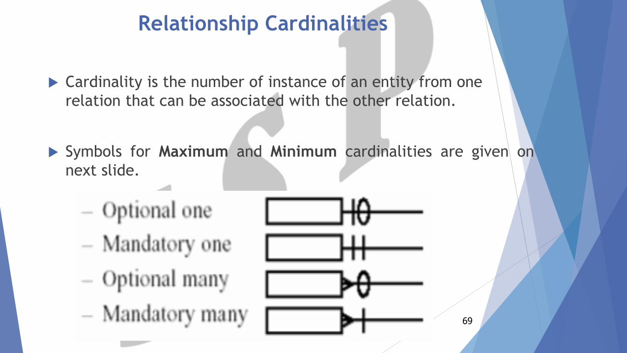
Relationship Cardinalities
Cardinality is the number of instance of an entity from one
relation that can be associated with the other relation.
Symbols for Maximum and Minimum cardinalities are given on
next slide.
69
70
Continued…
71
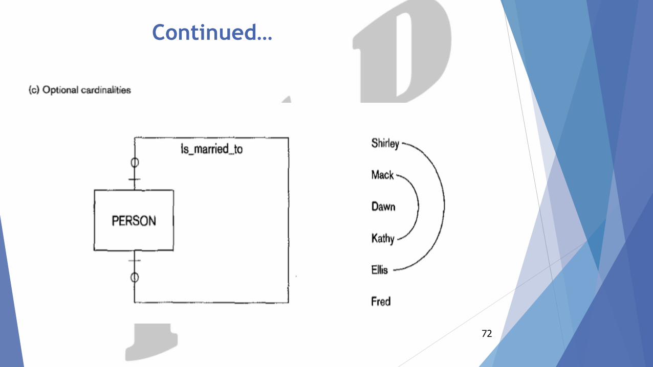
Continued…
72
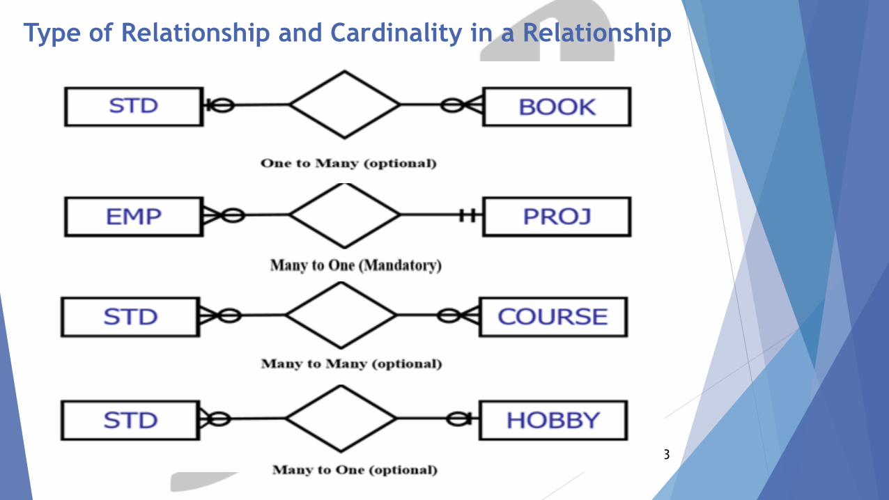
Continued…
Type of Relationship and Cardinality in a Relationship
73
74
ERD reading (Crow’s Foot Notation)
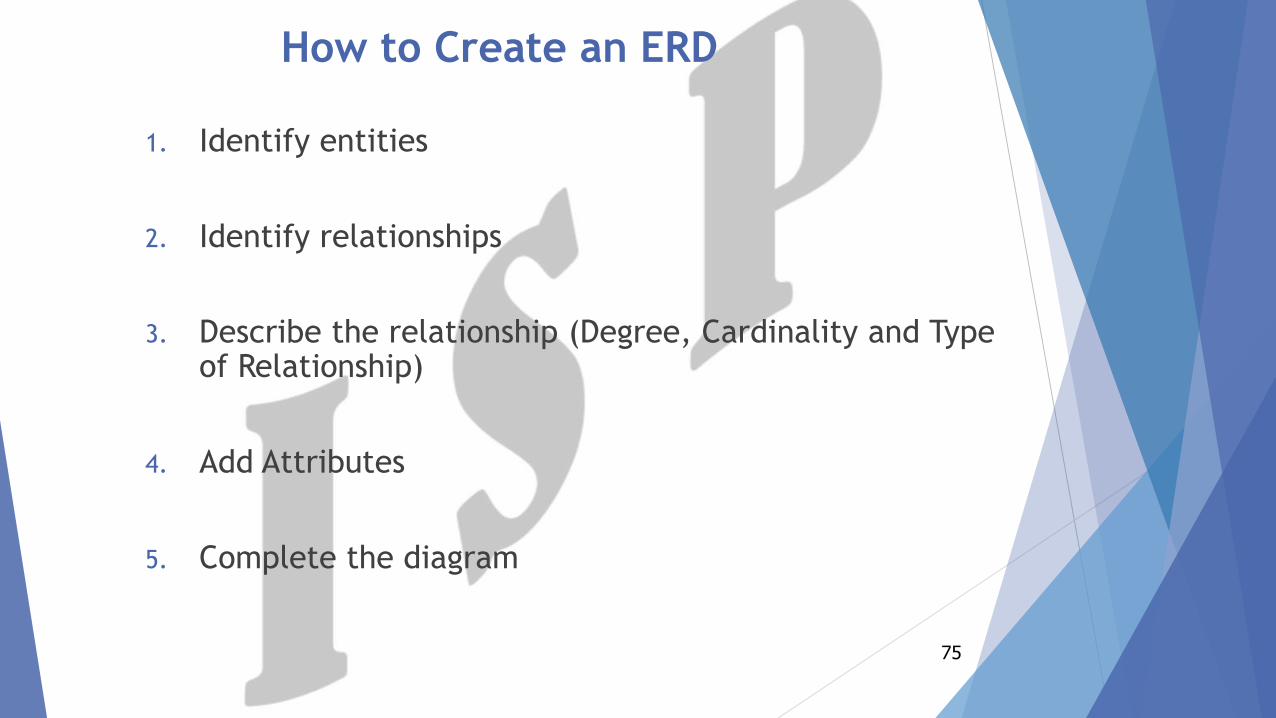
How to Create an ERD
1. Identify entities
2. Identify relationships
3. Describe the relationship (Degree, Cardinality and Type of Relationship)
4. Add Attributes
5. Complete the diagram
75
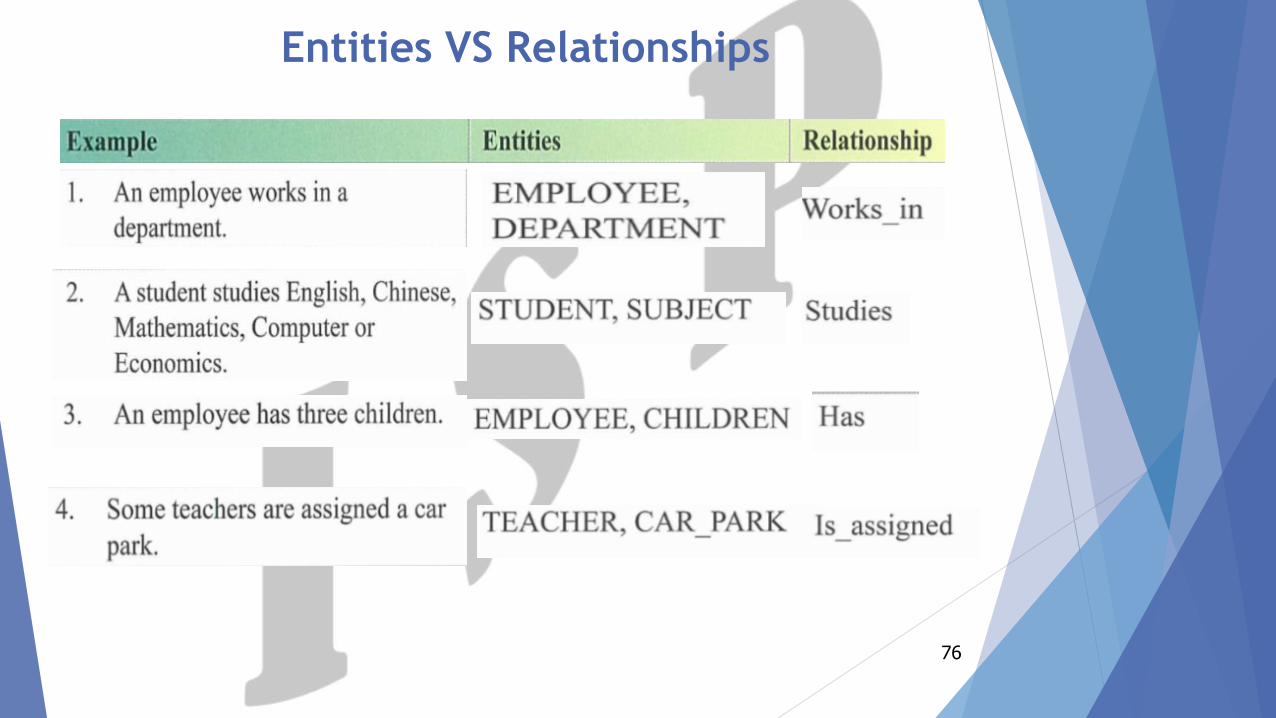
Entities VS Relationships
76
Scenarios
77
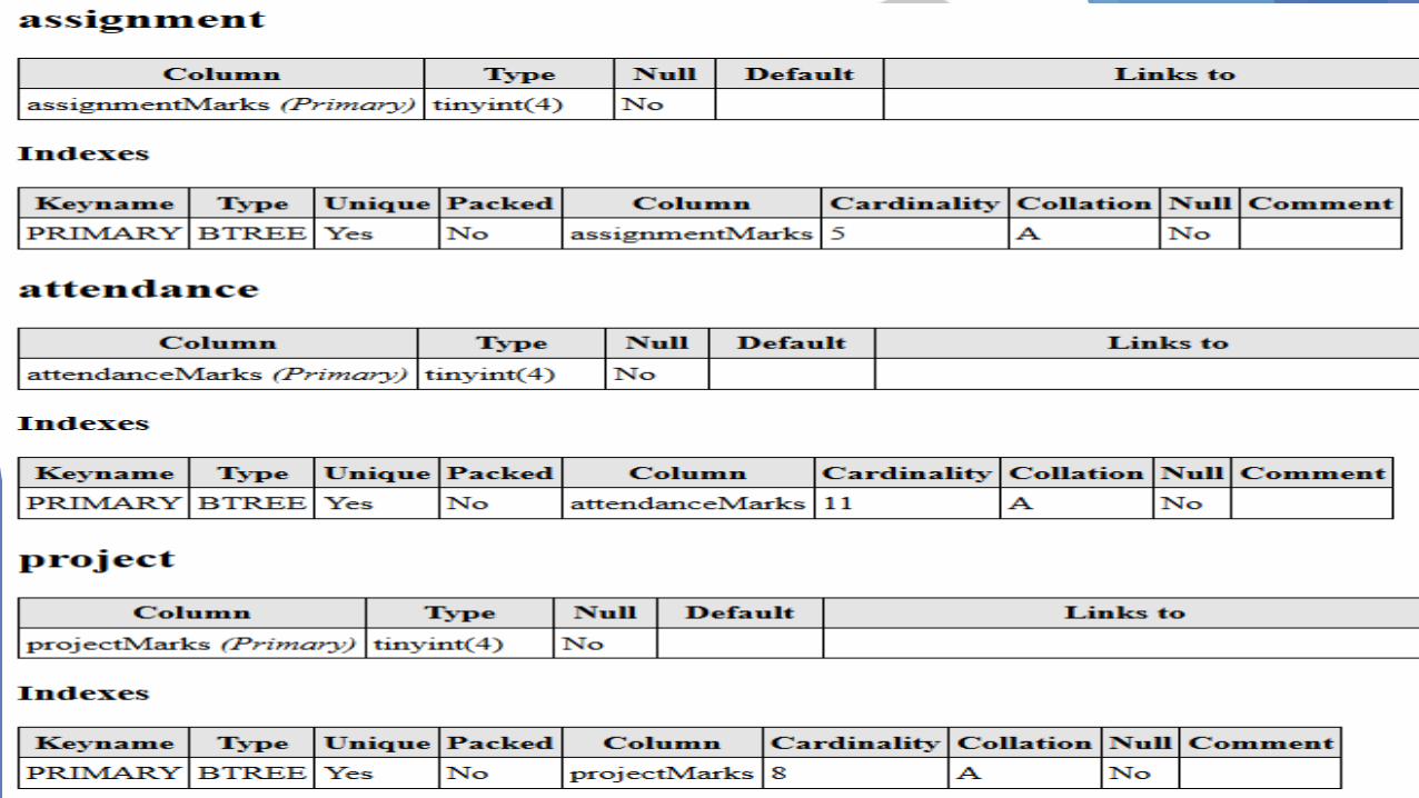
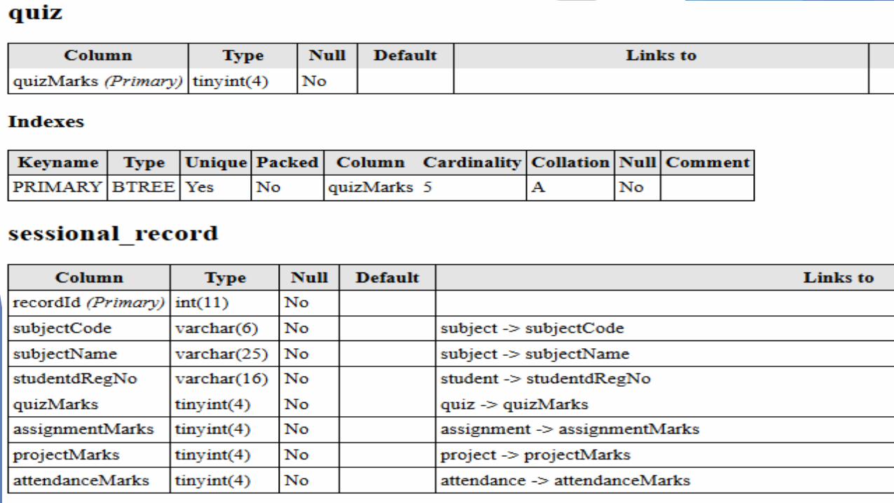
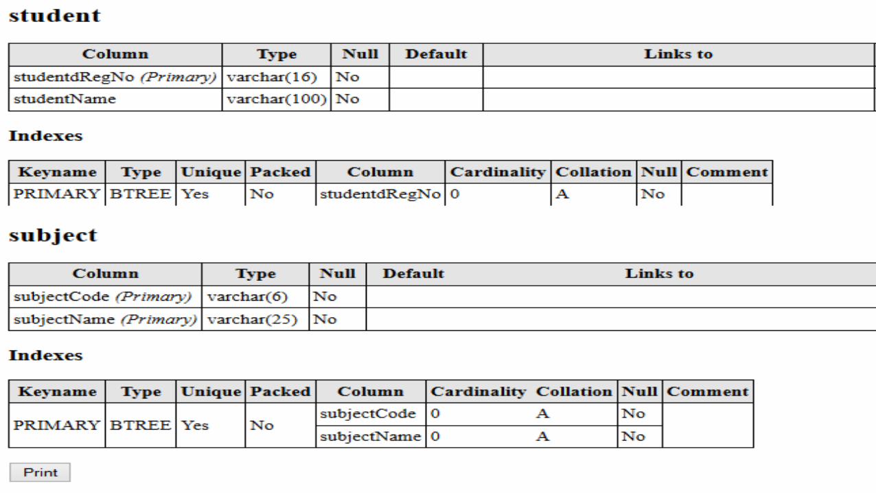
Data Dictionary
78
Data Dictionary
A data dictionary is a collection of descriptions of the data objects or
items in a data model for the benefit of programmers and others who
need to refer to them.
79
80
81
Continued…
82
Continued…
83
Relational Schema Diagram
84
Relational Schema Diagram
A relational schema diagram is the skeleton structure that
represents the conceptual view (transformed ERD) of the entire
database.
It defines how the data is organized and how the relations among
them are associated.
It expresses about the constraints/checks that are to be applied on
the data.
85
Continued…
86
ERD Reading
87
88
Continued…
89
Continued…
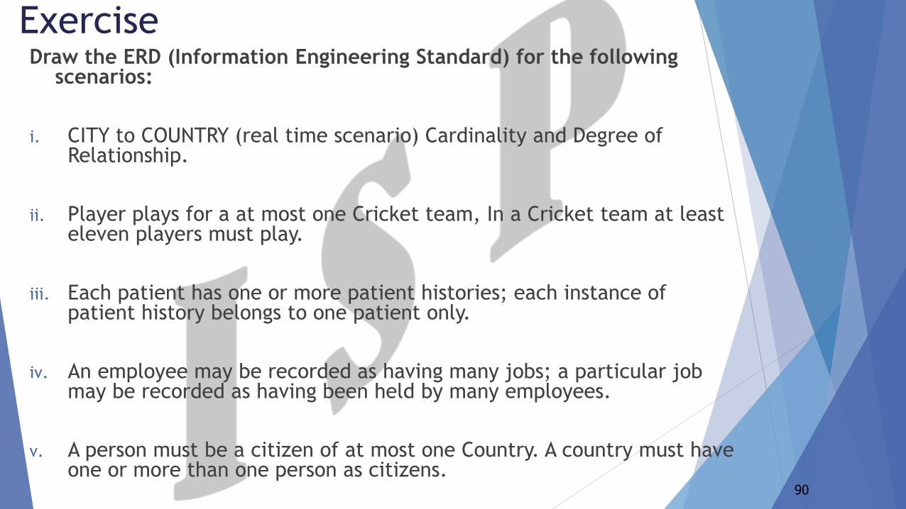
Draw the ERD (Information Engineering Standard) for the following scenarios:
i. CITY to COUNTRY (real time scenario) Cardinality and Degree of Relationship.
ii. Player plays for a at most one Cricket team, In a Cricket team at least eleven players must play.
iii. Each patient has one or more patient histories; each instance of patient history belongs to one patient only.
iv. An employee may be recorded as having many jobs; a particular job may be recorded as having been held by many employees.
v. A person must be a citizen of at most one Country. A country must have one or more than one person as citizens.
90
Exercise
91
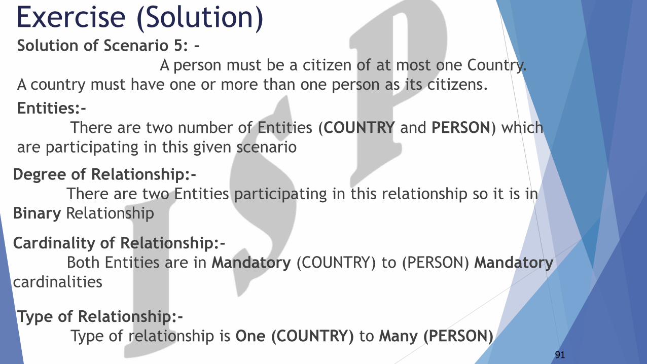
Exercise (Solution)Solution of Scenario 5: -
A person must be a citizen of at most one Country.
A country must have one or more than one person as its citizens.
Entities:-
There are two number of Entities (COUNTRY and PERSON) which
are participating in this given scenario
Degree of Relationship:-
There are two Entities participating in this relationship so it is in
Binary Relationship
Cardinality of Relationship:-
Both Entities are in Mandatory (COUNTRY) to (PERSON) Mandatory
cardinalities
Type of Relationship:-
Type of relationship is One (COUNTRY) to Many (PERSON)
92
93
1) Is the scenario on last slide is in Relational Database or inFlat File System?
It is in Relational Database because two tables relates with eachother with Primary Key and Foreign Key.
Primary Key (countryId in COUNTRY table)Foreign Key (countryId in PERSON table)
Because, Scenario is in One (COUNTRY) to Many (PERSON) typeof relationship.
94
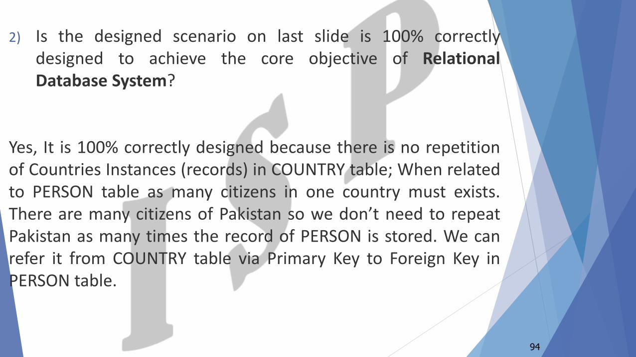
2) Is the designed scenario on last slide is 100% correctlydesigned to achieve the core objective of RelationalDatabase System?
Yes, It is 100% correctly designed because there is no repetitionof Countries Instances (records) in COUNTRY table; When relatedto PERSON table as many citizens in one country must exists.There are many citizens of Pakistan so we don’t need to repeatPakistan as many times the record of PERSON is stored. We canrefer it from COUNTRY table via Primary Key to Foreign Key inPERSON table.
95
3) If In Relational Database; Than, How it is minimizingDuplication of Data?
Duplication of Instances is removed because there is norepetition of Countries Instances in COUNTRY table. Countryinstance must be called via Foreign Key in PERSON table andthere are many number of instances of persons in PERSON tableas citizens of Pakistan, these instances can be related to a singleinstance of Country Pakistan in COUNTRY table.
96
4) Is it minimizing Update and Delete Anomaly/Irregularity?
Yes, We have removed Update and Delete Anomaly. WhenCountry instance is updated or deleted in COUNTRY table than itwill automatically show updated or deleted record againstcountryId in PERSON table where ever It is referred by ForeignKey. So, we don’t have to update or delete millions of records inPERSON table against countries.
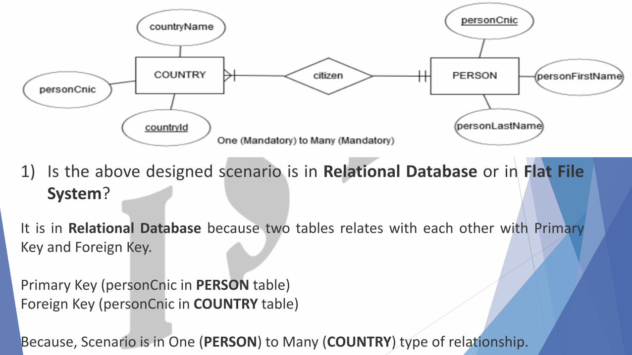
1) Is the above designed scenario is in Relational Database or in Flat FileSystem?
It is in Relational Database because two tables relates with each other with PrimaryKey and Foreign Key.
Primary Key (personCnic in PERSON table)Foreign Key (personCnic in COUNTRY table)
Because, Scenario is in One (PERSON) to Many (COUNTRY) type of relationship.
98
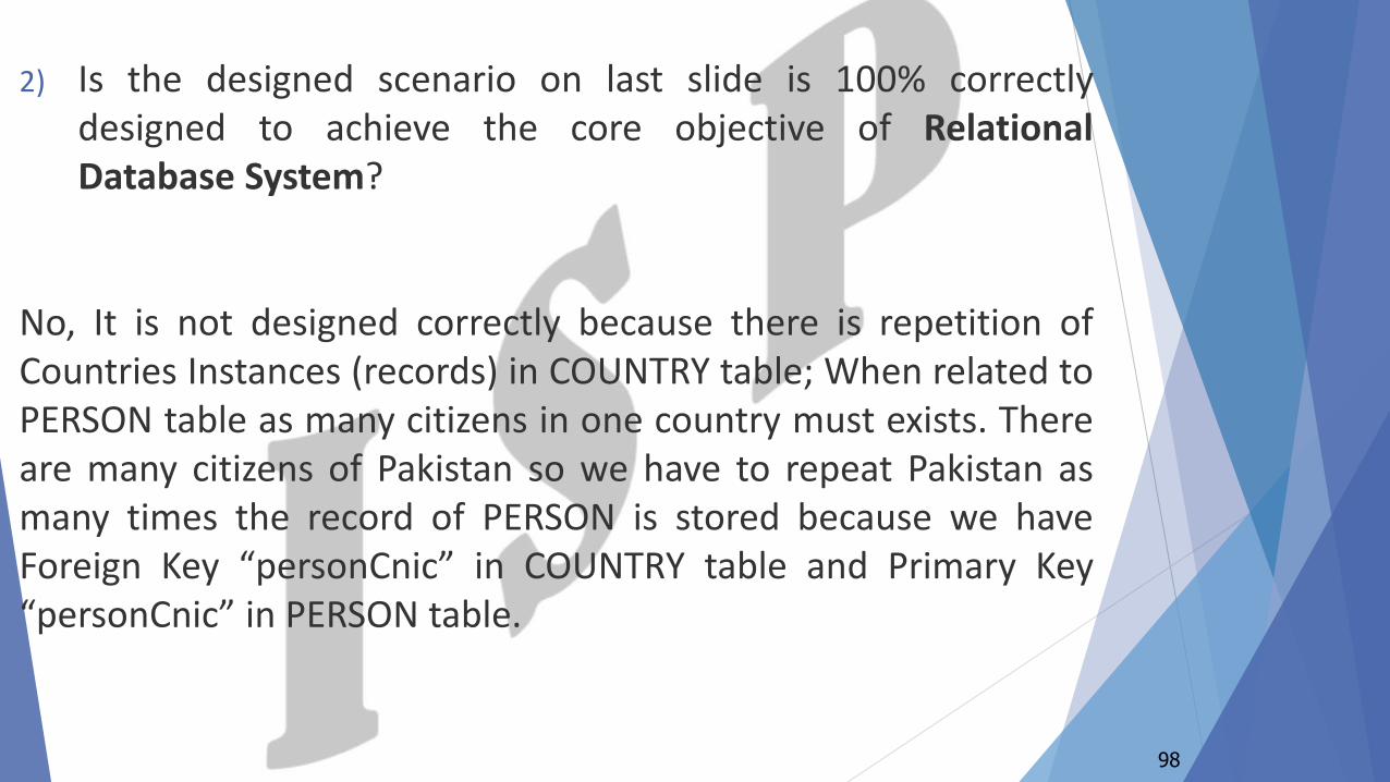
2) Is the designed scenario on last slide is 100% correctlydesigned to achieve the core objective of RelationalDatabase System?
No, It is not designed correctly because there is repetition ofCountries Instances (records) in COUNTRY table; When related toPERSON table as many citizens in one country must exists. Thereare many citizens of Pakistan so we have to repeat Pakistan asmany times the record of PERSON is stored because we haveForeign Key “personCnic” in COUNTRY table and Primary Key“personCnic” in PERSON table.
99
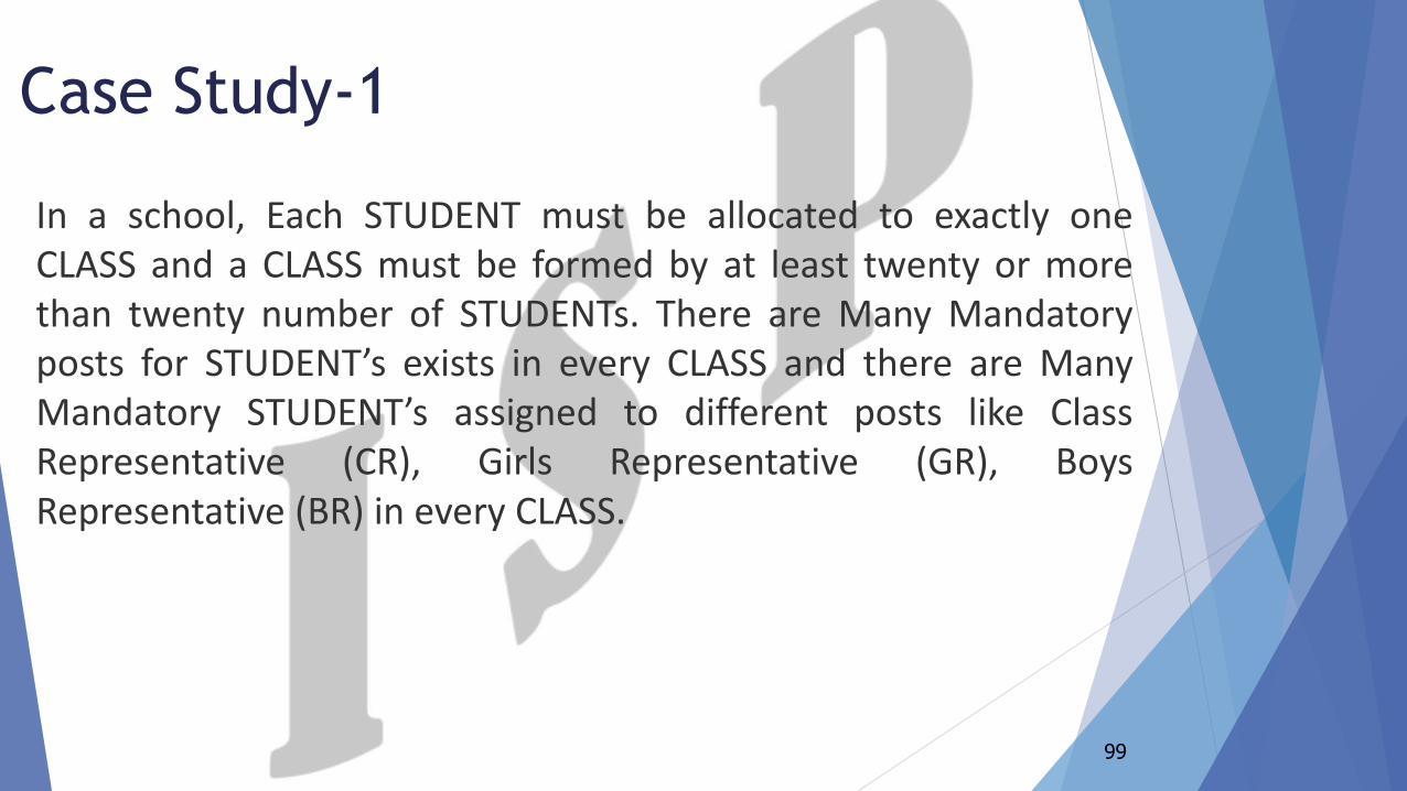
Case Study-1
In a school, Each STUDENT must be allocated to exactly oneCLASS and a CLASS must be formed by at least twenty or morethan twenty number of STUDENTs. There are Many Mandatoryposts for STUDENT’s exists in every CLASS and there are ManyMandatory STUDENT’s assigned to different posts like ClassRepresentative (CR), Girls Representative (GR), BoysRepresentative (BR) in every CLASS.
Step 1: Identifying Entities: -
STUDENT
CLASS
100
Entities
101
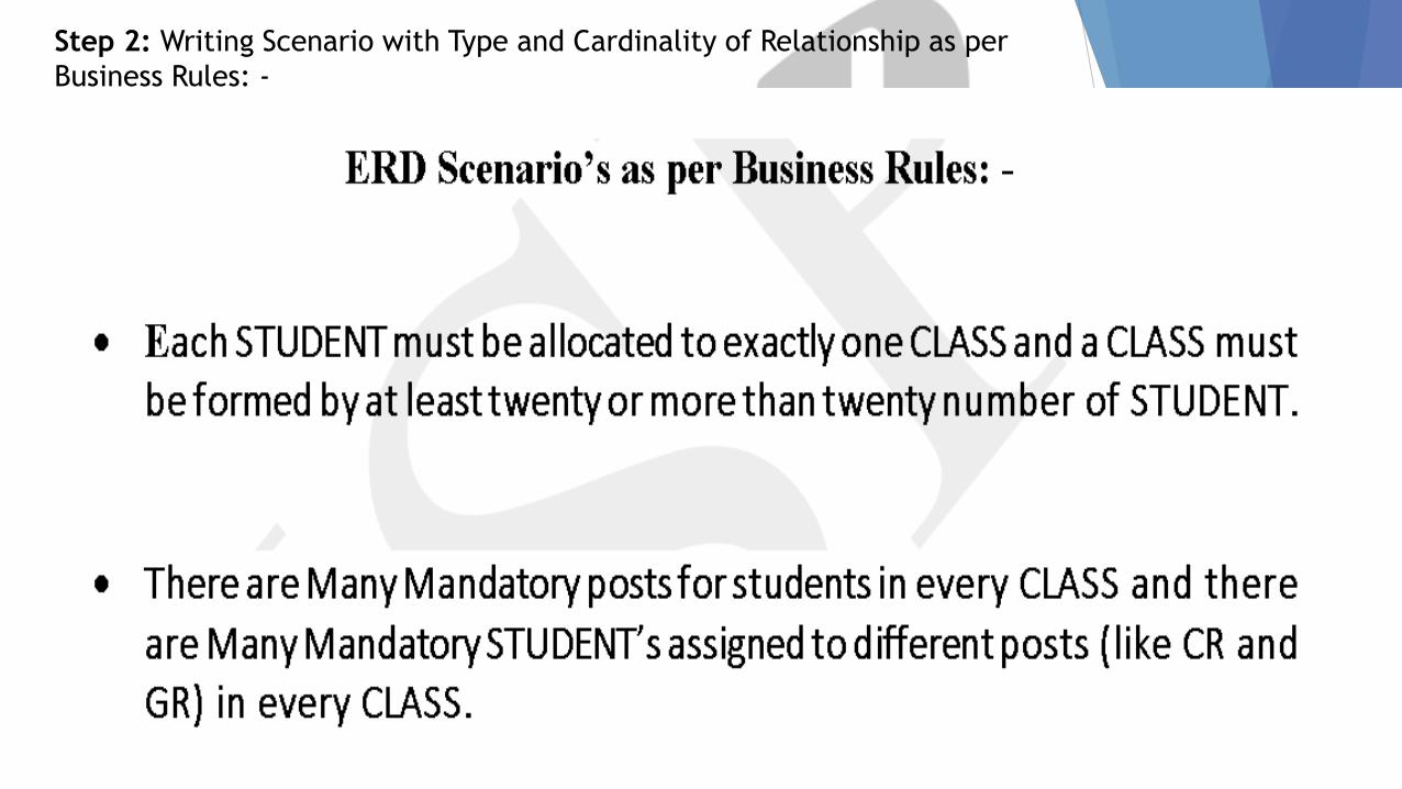
Step 2: Writing Scenario with Type and Cardinality of Relationship as per
Business Rules: -
102
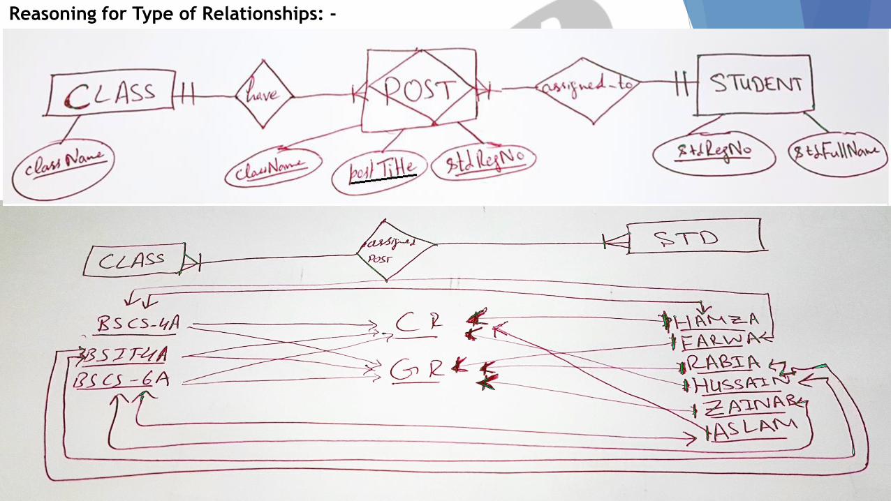
Reasoning for Type of Relationships: -
103
Step 3: ERD Designing in Information Engineering Style: -
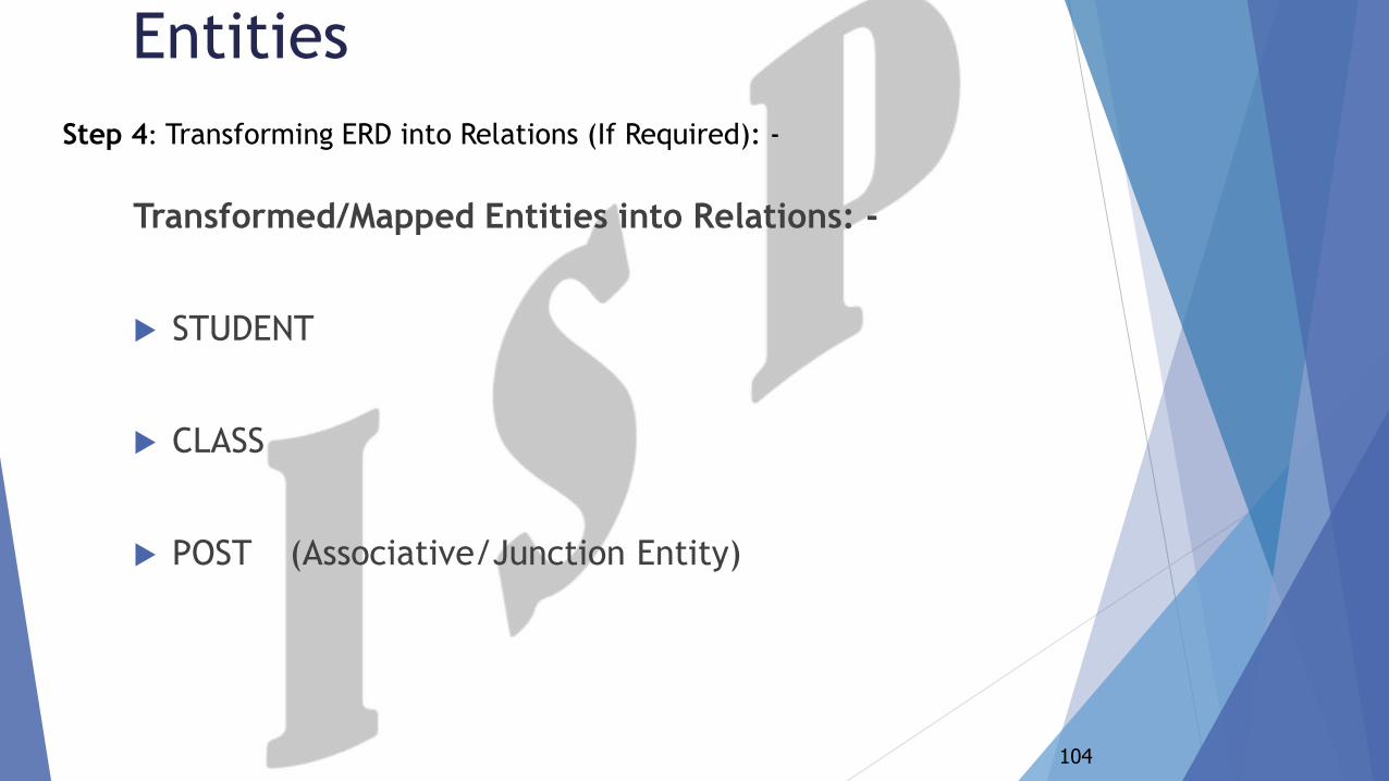
Transformed/Mapped Entities into Relations: -
STUDENT
CLASS
POST (Associative/Junction Entity)
104
Entities
Step 4: Transforming ERD into Relations (If Required): -
105
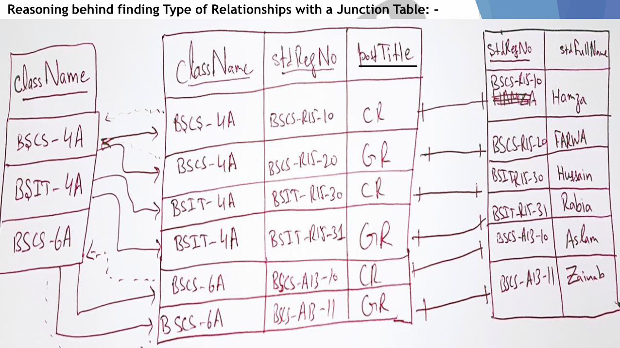
Reasoning behind finding Type of Relationships with a Junction Table: -
106
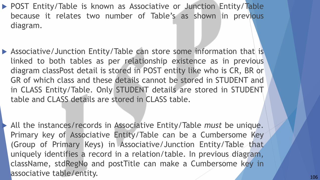
POST Entity/Table is known as Associative or Junction Entity/Table
because it relates two number of Table’s as shown in previous
diagram.
Associative/Junction Entity/Table can store some information that is
linked to both tables as per relationship existence as in previous
diagram classPost detail is stored in POST entity like who is CR, BR or
GR of which class and these details cannot be stored in STUDENT and
in CLASS Entity/Table. Only STUDENT details are stored in STUDENT
table and CLASS details are stored in CLASS table.
All the instances/records in Associative Entity/Table must be unique.
Primary key of Associative Entity/Table can be a Cumbersome Key
(Group of Primary Keys) in Associative/Junction Entity/Table that
uniquely identifies a record in a relation/table. In previous diagram,
className, stdRegNo and postTitle can make a Cumbersome key in
associative table/entity.
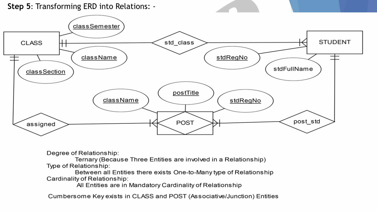
Step 5: Transforming ERD into Relations: -
Odeon Cinema and other international cinemas have decided to
install a centralized database. This database should keep
information regarding cinemas including its name, address and
phone number. Each cinema must have one or more theaters and
each theater has a specific showing time. During these showing
times a particular movie is shown to the general public
108
Case Study-2
CINEMA
THEATER
SHOW
MOVIE
109
Entities
A CINEMA must contain one or more THEATERs. A THEATER must
belong to only and only one CINEMA.
A THEATER has one or more SHOW times. A particular SHOW time
for a movie must belongs to only and only one THEATER.
A MOVIE may have many SHOW times and a particular SHOW time
must belongs to one MOVIE only.
110
Relationships
ERD Online Simulator: -
https://erdplus.com/#/standalone
https://www.lucidchart.com
Desktop Simulators for ERD: -
Smart Draw
RISE Editor
Rational Rose
111
ERD Simulators/Tools
Prediction Database System (A system which can dynamically predict
and changes record where required)
Any Database Management System (Any System which must manage
real time instance of data)
Important Note:
1. All Projects must dynamically changes record; Based on Parent
Table’s record.
112
Projects Recommendation
Recommended Readings
Chapter 3 from:
Modern Database Management-8th Edition by Jeffrey A. Hoffer,
Mary B. Prescott & Fred R. McFadden (Page No. 116-171)
Chapter 11 from:
Database Systems-A Practical Approach to Design,
Implementation and Management by Thomas Connolly and
Carolyn BEGG, 4th Edition (Page No. 393-421)
Chapter 4 from:
Database Systems - Design, Implementation, and Management by
Carlos, Steven and Peter, 9th Edition (Page No. 129-176)


![Multan Uncontested PTI Punjab Intra Party Election Results [updated 22th Feb 2013]](https://static.documents.pub/doc/80x56/545a7393af79590b088b5b31/multan-uncontested-pti-punjab-intra-party-election-results-updated-22th-feb-2013.jpg)


