DOCUMENT RESUME s .ED 259 132 A O 'CE 041 757 TITLE Fundamentals- of Diesel Engines. INSTITUTION Marine Corps Inst., Washington, DC. 4 REPORTNO MCI- 13.35a PUB DATE 5 Dec 84 ;, 'NOTE 112p. PUB letiPE Guides?- Classroom Use Materials (For Learner) (0451) .0. ( -411 EDRS PRICE MF01/PC05 Plus Postage. t DESCRIPTORS *Auto Mechanics; Correspondence !Independent *Diesel Engines; *Equipment Maintenance; Independent Study; Military Personnel; *Military Training; Postsecondary Education; *Small Engine Mechanics;. *Trtde and 'Industrial Education. . ABSTRACT' This student guide, one of a series of correspondence training courses designed to.improve the job performance of members,r, of the Marine Corps, deals mith the fundamentals of diesel engine mechanics. Addressed in the three individual units of the course,,are: the following topics: basic principle of diesel mechanics; principles, mechanici, and performance of-diesel enkgines; and injection and control of diesel engines. Each unit contai 'hs a general objective, a. series of work units each addressing a different subobjective, study questions, and answersitO the study quest' ns \,/* Appendixes to the guide contain a conversion chart and reference oo information concerning the mathematics of diesel engine theory, energy, temperature, and pressure and volume. (MN) r 4. t *********************************************************************** * Reproductions supplied by EDRS are the best that can be made from the original docent. ****************i******************4***************$*******************
Transcript
DOCUMENT RESUMEs
.ED 259 132
A
O
'CE 041 757
TITLE Fundamentals- of Diesel Engines.INSTITUTION Marine Corps Inst., Washington, DC.
4
REPORTNO MCI- 13.35aPUB DATE 5 Dec 84
;,
'NOTE 112p.PUB letiPE Guides?- Classroom Use Materials (For Learner)
ABSTRACT'This student guide, one of a series of correspondence
training courses designed to.improve the job performance of members,r,of the Marine Corps, deals mith the fundamentals of diesel enginemechanics. Addressed in the three individual units of the course,,are:the following topics: basic principle of diesel mechanics;principles, mechanici, and performance of-diesel enkgines; andinjection and control of diesel engines. Each unit contai 'hs a generalobjective, a. series of work units each addressing a differentsubobjective, study questions, and answersitO the study quest' ns
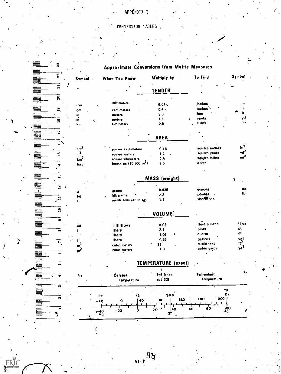
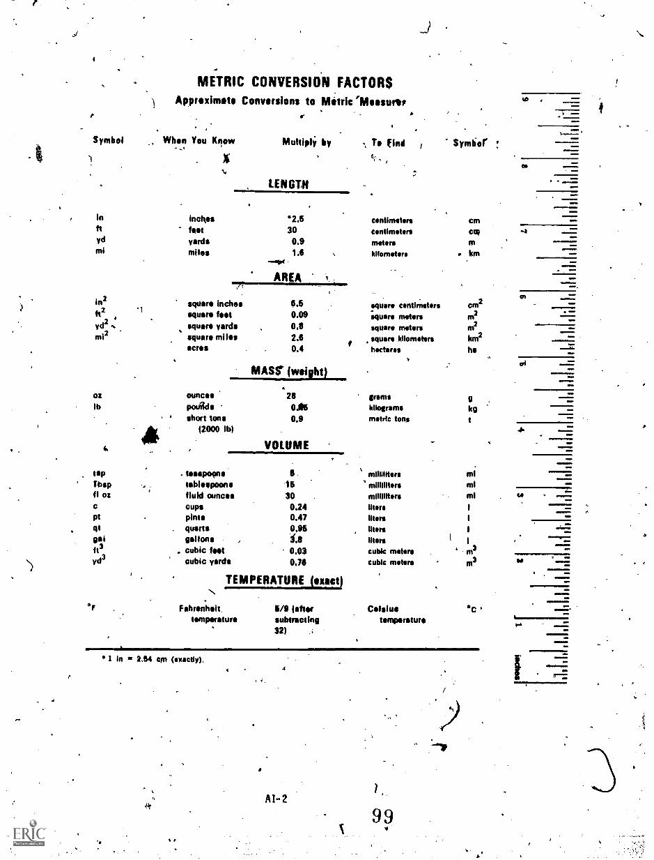
\,/* Appendixes to the guide contain a conversion chart and reference oo
information concerning the mathematics of diesel engine theory,energy, temperature, and pressure and volume. (MN)
r 4.
t
************************************************************************ Reproductions supplied by EDRS are the best that can be made
from the original docent.****************i******************4***************$*******************
I
1. ORIGIN
MCI course 13.35a, Fundamentals of Diesel Engines, has been prepared
UNITED STATES WARM CORPSMARINE CORPS INSTITUTE. MARINE BARRACKS
DOS 1776ARLINGTON. VA. aissa10001
V
0045 Dec 84
by, the Marine Corps Institute.
2 APPLICABILITY
This course is for instructional purposes only.
I-
A44
4.
O
N
A
11,
J.41. D.,NOLLADAYLieutenant Colonel, U. S. Marine Corps
Deputy Director
0
1.
v
* rl
ACKNOWLED(IENT
The Marine Corps Institute, Marine ,Barracks, '',Washington, NC., gisatefully.acknowledges the important contributions provided by the following MCIpersonnel in developing and publishing this course:
t, -t
nurse Developer GySgt James 'R. YounceOfficer in Charge Capt David G. ReistEducation Specialist 1 Ms. Betsy A. McCleary,Course Editortor. Pis Monica L. Noell $3.Wordproctssing Technicians Cpl Ron D. Cul p
Cpl Sheri, R. Arms teaLCp1 Lamont E. Brook
Graphics Illustrator /t Cpl Ron Frankhouser
The !trine Corps Institute, Marine' Barracks, Washington, D. C. gratefullyacknowledges the important contributions provided by the Engineer EquipmentInstrUction company. Marine Corps Engineer School , Marine Corps Base, CampLeJeune, North Carolina, for their assistance in the validation and formalreview of this course.
4
INFORMATION
FOR .,
MCI STVD6TS
MCILR241-NRL,
J
Welcome to the Marine Corpinstitute training program. Your interest in
self-improvemdnt and ikreisell'profe'ssional competence is commendable.4
Information is provided telow to Assist ydu in completing th# course.
Please read this guidance before proceeding with your studies.
.1. MATERIALS
Check your course materials. 'You should have all, the materid+s listed-in
the "Course. Introduction." In addition you should have an envelope to mail
your review lesson back to MCI for grading unless your review lesson answer
, sheet is of the self-mailing type. If your answer sheet is the pre-printed. type, check to see that your name,, rank, and social security number are
correct. Check closely, your MCI-records are kept, on a computer and any
414; discrepancy in the above information may cause your "subsequent activity to go,
unrecorded. You may correct the information directly on the ap,mgr sheet., If
you did not receive all your materials, notify your training FICO: If you are
not attached to a Marine Corps unit, request them through the Hotline (autovpn
288-4175 or commercial 202-433-4175).. / u
) 2. LESSON SUBMISSION
. The self-graded exercises contained in your course at.e not to be returned'. .
.
to MCI. Only the completed review lesson answer sheet should be mailed to
MCI. The answer skeet is to be completed and tailed only after you have
finished all' of the study units in .the course -booklet. The review lesson has
been designed to prepare you for the final examination.
It is important that you provide the required information at the bottom of
your review lesson answer sheet if, it does not have your name and address l
printed on its In courses in which' the work is submitted on blank paper/or r
printed forMs, identify each sheet in the following manner;
POE, John J. Sgt '332-11-9999'08.4g, Forward ObservationReview LessonMilttarror office address(RUCnumber, if available) 301.
Submit your review lesson on the answerheet and/or forml,provided.
Complete all blocks and4ollow the directions on the answer s 'heet for
mailtng. Otherwise, your answer sheet may be delayed or lost. If you have to
interrupt ydur studiv for any reason and find that you eannot,complete your
course in one year,jou may request a single six month,eltension by contacting
your training NCO, at least One month prior to your courser completion deadline
date. If you are not attached to a Marine Corps unit you may make this 1
requ9st by letter. Your commanding officer is.notified monthly of your status
through the monthly Unit .,Activity Report. In; the gvent of difficulty, contact
. your training NCO or MCI immediately.
,
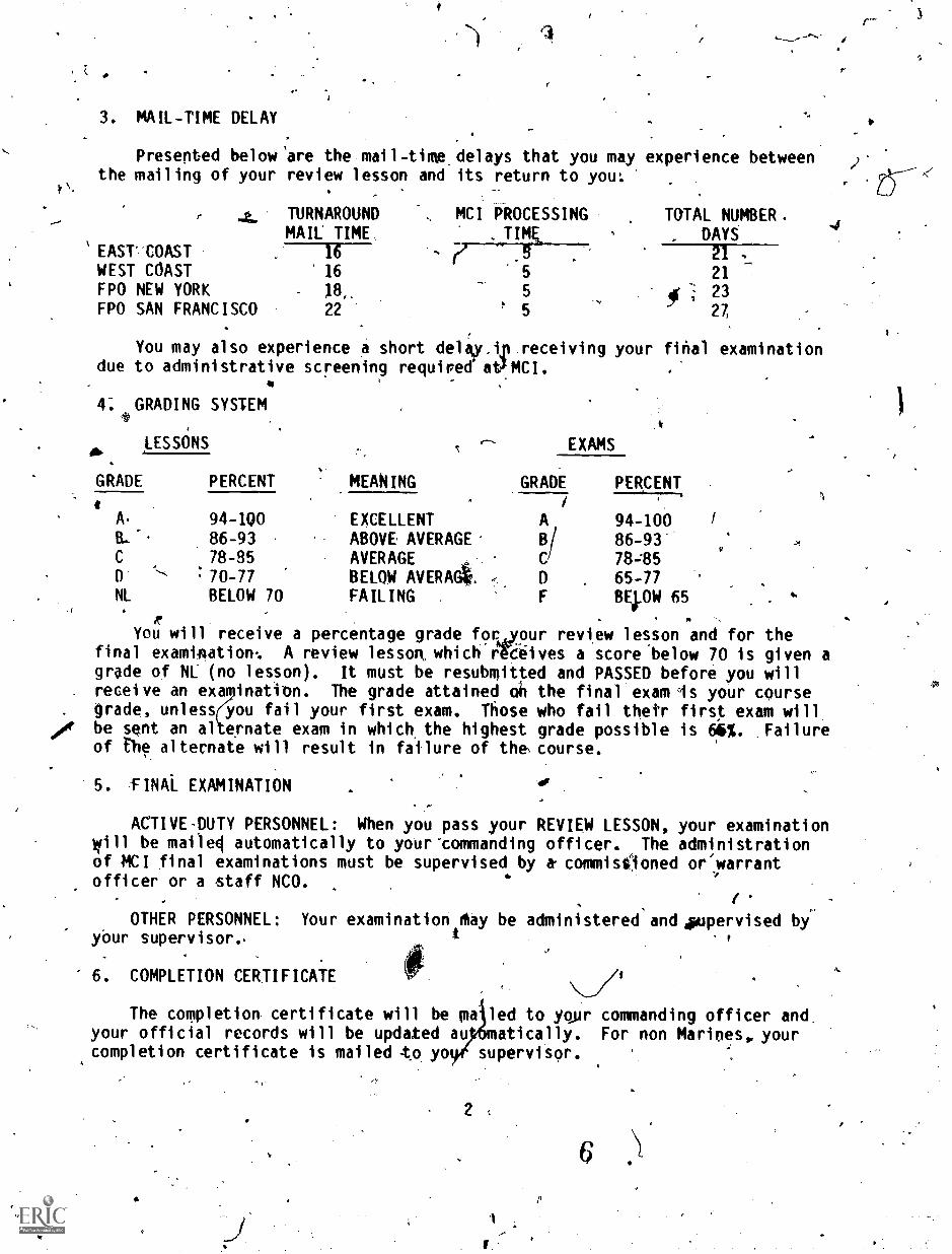
3. MAIL-TIME DELAY
Presented below are the mail-time,delays that you may experience betweenthe mailing of your review lesson and its return to you
, ..it.' TURNAROUNDMAIL TIME
EAST COAST 16
WEST COAST 16
FPO NEW YORK 18_FPO SAN FRANCISCO 22
. MCI PROCESSING TOTAL NUMBER.. TIME., DAYS
, ., 5 21 ,
5 21
5 10* ;. 23! 5 ,
27
You may also experience a short delay,tp receiving your final examinationdue to administrative screening requiredatMCI.
4: GRADING SYSTEM,I)
it
LESSONS t,, EXAMS
gib
GRADE PERCENT MEANING GRADE PERCENT. i
I
A. 94 -1QO EXCELLENT A 94-100B. -. 86-93 ABOVE, AVERAGE 111/ 86 -93
C 78-85 AVERAGE e C 78-85D- '''- . 70-77 BELOW AVERAG, D , 65-77NL BELOW 70 FAILING . F BE,I.OW 65
r .
You will receive a percentage grade for Tur review lesson and for thefinal examination: A review lesson° whichrYciives a score below 70 is given agrade of NL (no lesson). It must be resubmitted and PASSED before you will
. receive an exa ination. The grade attained oh the final exam Is your coursegrade, unless you fail your first exam. Those who fail their first exam will
oogt be sent an al ernate exam in which the highest grade possible is 6b%. Failureof the alternate will result in fiilure of the course.
5. -FINAL EXAMINATION
ACTIVE-DUTY PERSONNEL: When you pass your REVIEW LESSON, your examinationwill be mailel automatically to your-commanding officer. The administrationof MCI final examinations must be supervised by a- commissioned or/warrantofficer or a staff NCO.
. 1.
,
OTHER PERSONNEL: Your examinationtMay be administered and Appervised by-
your supervisor.
e6. COMPLETION CERTIFICATE
The completion certificate will be pa led to your commanding officer and,your official records will be updated au atically. For non Marines, yourcompletion certificate is mailed -to yo supervisor.
2
rc.
7. RESERVE RETIREMENT CREDITS .
I
,4-
Reserve retirement credits are awarded to inactive'd4ty personnel bill*.
Credits awarded for each course Wee listed in the "Course Introduction:"treditS are only awarded upon successful- completion of the course. Rese'rve
retirement credits are not awarded fors MCI study'perform4d during drillperiods if credits are -also awarded for drill attendance.-
,
8: DISENROLLMENTorT
Only your commanding officer can request your disenrollment from an MCI
course. However, an automatic disenrollment occurs if the course is not_completed (including the final exam) bi the time you reach the CCD (coursecompletion deadline) or the ACCD (adjus urse'comrletion deadline) date.
Thisection will adversely affect the, it'.s c fetion mate.
9. ASSISTANCE II?4
)
iConsult you training NCO if iou have'questions concerning coursecontent. Should he/she be unable to assist' you, MCI is ready to help you '-
whenever you need it. Please use the Student Course Content AssistanceRequest1ForM-(ISDL1) attached to the end of your course booklet _pr call on of
the AUTOVON telephone numbers listed below, for the appropriate course writer
For administrative problems use the UAR or call the MCI HOTLINE: 288-4175.
For commercial phone lines, uge area code 202 and prefix 433 instead of
288.
r
Xt.
3
U.S. GOVERNMENT PRINTING 0#PICE C1' b4 0 492-363
74,
a41,
24.
`,/, t,_ : ...
; I PREFACE,
, .,
FUNDAMENTALS OF DIESEL 'ENGINES has been des' red to provi de engineer equipmentMechanics, MOS 1341, sergeants and below, with,a source of study material on the basic \)fundamentals of diesel engines. The course will pse bkbeneficial to those Marines in
.occupational fields 17, 18, 21, and 35 witose Jobstequire them to work clotely pith diesels'engines. FUNDAMENTALS OF DIESEL ENGINES provides road _coverage on dieel engine princi pl es ,. purposes 411, advantages , disadvantages, engine co ucti oh , fuel injection ,° combustion'-and.con troll ing theengzine , ,
.,. II
,. .,so. . ...
NAVEDTRA Diesel Engines; 197* : ...
TM 9-8000/T036A-1-76 Principles of Autolotive Vehicles, Jan 19567M-2815:15/1 V-71 Detroit Dieseljngines, 1972 v IP . \
t
1
8
41,
45
at
841
R0
FUNDAMENTALS OF DIESEL ENGINES
COURSE INTRODUCTION
..:The pup Se of this'text islpo serve as a source of information and wtraining aid for
mechanics working on internal:combustion engines of the diesel design. The course is,designed
,.:... to present arruncluttered view of just theifundaMelltals of diesel Engines, i.e.,,engineconstruction, diesel engine princio4es, engine performance, engine mectiMiics,. structuralengine parts', injecting the fuel, burning the fue), and controlling the engine. Engine ,
systems and auxiliaries are covered in other courses offered by MCI. A sound understanding $f ,
the fundamentals of diesel engines win enable' the mechanic working on diesel engines to - .
understand diesel malfunctions and inadequate performance.
I
1
The diesel.engine Dears the name of Dr. Rudolph Diesel, a German engineer. He is
credited with constructing' the first successful diesel engine using liquid, fuel in 1897. His
objective was an engine with greaten fuel economy than the steam engine which used only asmall percentage of the energy contained in the coal burned under its boilers. Dr. Diesel
Aginally planned to use pulverized coal as fuel, but first experimental engine in 1892r
was a failure. After a second engine also failed, he c nged his plan and used liquid fuelThe engine then proved successful. /
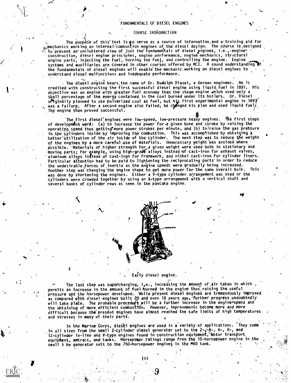
The first diesel'engines were low-speed, low-pressure heavy engines. 'the first steps
of developmAnt werk: (a) to increase the power fora given bore and stroke by raising theoperating speed thus gettin4'more power strokes per minute, and (b) to'raise thegas pressurein the cytinders inside by improving the combustion. This was accomplished by obtaining.befter-utilization of the air inside of the cylinder. The next step was to reduce Vie weight
of the engines;by a more careful-..use of matetials. Unnecessary weight was avoided wherepossible. -Materials of higher strength for a given weight were used both in. stationary andmoving parts; for example, using high -grad alloys instead of cast-iron for exhaust valves,aluminum alloys inftead of cast-irpn for framework, and nickel cast-iron for cylinder liners.Particular attention had to be paid to lightening the reciprocating parts'in order to reducethe undesirable. forces of inertia as the engine speeds were gradually being increased.Another step was' changing the engine shape to get more power for the same overall bulk. This
was done by shortening the engines. Either a V-type cylinder.arrangement was used or thecylinders were crowded together by using an X,-type arrangement with a vertical shaft andseveral banks of cylinder rows as seen in the pancake engine.
0
4
7
. Eahy diesel engine.
1
The last step was supercharging, i,e., increasing the amount ofair taken in whichpermits an increase in the amount of fuel-turned in the engine thuilraising the usefulpressure apd the horsepower developed. While present diesel engines are tremendously improved
as compared wth diesel engines built 0 and even 10 years ago,Turther progress undoubtedly
will take pla e. The probable prOce ill be a further increase in the engineospeed and
the obtaining of more efficient combus n. However, improvements become more and moredifficult because the'present engines have almost reached the safe limits of high temperaturesand stresses in many of-their parti.
In the Marine Corps, dieeel engines are used in a variety of applications. They come
in all sizes from the small 2-cylinder diesel generator set to the 2-1A-, 6-, 8-, and12-cylinder in-line and V-type engines found in construction equipmetili-iotor transport,
equipMent, amtracs, and tanks. Horsepoker ratings range from the 10-horsepower engine in the
small 5 kw generator sets to the 750-horsepower engines in the M60 tank. , r
u.
111 .`
a
L
(.)
1
A thorough understanding of the fundamentals of internal-combustion engineS aspresented in this course is importantlor several reasons. First, ft is essential for anunderstanding of the.opecation of various engines and the functions of the different parts.It is much easier for a person to do something properly when he understands the reasoningbehind it. The understanding of the .fundamentals underlying the operatton of different engineparts helps to prevent undesirable operating conditions and thus reduces maintenanceproblems. A proper understanding.of the fundamentals helps to solwe ndw,problems of operationand maintenance and suggests how to meet new conditions of operation. Fdrthermore, a good*understanding of the fundamentals will he)p in dealing with an- engine of a new type or a newdesign, since the basic principles for all engines are the same. The different shepe of acertain engine part will not.confuse a person Oho understands the purpose and operatingconditions, of that pact or piece of auxiliary equipment. In case`you, as a diesel mechanic,have to use a helper who has not received diesel engine training or have to teach a man totake yoUr`place in an emergency, a. thorough understanding of the fundamentals will beinvaluable. When the new man asks why, you will be able o answer. At the same tfme; it iswell to remember that studying frim a boa is not'enoug regardless of how good the book maybe. It takes several ye rs ofNpractical experience in o erating and svrvicing Aiese1 enginesof various types to beco e a real diesel mechanic.
17:;
.1
OBI
lv
.st
N
t
Study; Unit"Nu* er
1
2.
3
StudyHours
4IE
FUNDAMENTALS OF DIESEL 604E1
ADM IN IS7RATI VE INFORMAT IONORDER OF STUDIES
Subject Matter 23" Basic Pr inci pl egt
3 Principles, Mech art ics , an d Per fro mance
4 Injection and Control
2 REVIEW LESSON
2 FINAL EXAMINATION
RESERVE RETIREMENT`CREDITS:"
COLLEGE CREDITS'.
EXAMINATION:
, 'MATERIALS:
41,
C
5
American Council on Education (ACE) has awarded 13.35a,FUNDAMENTALS OF DIESEL ENGINES, 3 semester hours in Fundamentals ofDiesel Engines fa the Vocational Certificate Category.
Supervised final examination without textbook or notes; time limit2 hours.
RETURN OFMATERIALS: STUDENTS who successfully complete this course are permitted to
keep the course materials.
/Students disenrolled for inactivity or at the request of theircommanding officers will -return all course materials.
4.
HOW TO TAKE THIS. COURSE
or
1
Not. This course contains three study units. Each study unit begins .with. a gener.41objective that is a statentent of *at you should learn from the'study unit. The study unitsare divided into numbered work units, each presenting one or more specific objectives. Readthe objective(s) and then the work unit text. At the end of the work unit text. are questionsthat you should be able to answer without referring to the text of the work 'unit. Afteranswering the questions, check yo answers with those listed at the ena of the study. unit.If you Miss any of the questions , ou 'should restudy the text of the work unit until youunderstand e correct responses. When you have mastered one study unit, move onto thenepct, Aft 'you have completed all of the study units, complete the review lesson and take itto your training officer or NCO for mailing to MCI. MCI will mail the final examination toyour training officer or NCO when you pass the review lesson.
ti
(
4.4
PrefaceSource Materla sCourse Lntrod tion
Table of. ContentsStudy. Guide
TABLE OF ,CONTENTS
Work Unit
. OOOOO
ti
PAR
Study Unit 1. BASIC PRINCIPLES .
Basic principles of the diesel engineEngine construction i.Engine classesEngine measurements ..
,
Engine outputEngine efficiency'
:
c
The main stationary parts of the diesel engineThe main. moving parts of the diesel engine
',;Atudy Unit 2. PRINCIPLES, MECHANICS, AND PERFORMANCEOF THE DIESEL ENGINE
Operating principlesThe different methods of scavenging /
The differences ift,a comparison between the gasolines and diesel
EnginlesThe r6echanics of piston and frank travelCombustion and ignition delay ,
,
Ignition aid timing,SuperchargIng .4.
,, ,
"'Study Unit 3. INJkCTION AND CONTROL OF THE DIESEL ENGINE
4
4.
,
1-1
1-2
0-31-4
1 -5
1-6
1-7
1-8
2-1
2-2
2-3
2-42 -5
2-62-7'
1-1
1--?
1-3 '
1-6
1-8 -
1-1314-15
1-18
2 -1
2'-6
.*
2-92-11
2-122-15
NI.2L16
Fuel injection systemsMechanical injection systemsCombugrtion within the diesel engine .
Diesel engine loadsFunctions and usages of the governor on the diesel engine . .
Review Lesson
Appendixes
3-1 , 3-1
3-2 3-33-3' , 3-13
3-4 3-17 A3-5 3-19
R-1
Conversion chart AI
Mathematics of diesel engine theory , '-
,--4 All
Energy AIII
Temperature . 106. AIV
Pressure and volume . . . AV --
A
'J.
GP
)12
i.
P
L
qa *
MARINE tORPS INSTITUTE
Welcome to the Marine CorpsInstitute correspondence training pro-gram; -By edrolling in this. cours % youhave shown a desire ttz improve`th .
iskills,you need for effe_Ove job perfor-mance, and MCI has provided materialsto help yot; achieve Your goal. Now allyou need is to develop your owtritliethodfor using tigke materials to best advan- ,
tage,
The following g aiderines presenta four-part approach to completing yburMCI course successfully:
-1. Make a. "reconnaissance" ofJ our mattrials:
, Plan your study time and choosea good study environment;
3. Study thoroughly and system-atically;
4, Prepare for the final exam.
MANE A "RECONNYOUR MATERIAIS
Begin with .a look Sit the courseintroduction page. Read the COI`RSEINTRODUCTION to get the "big pictui:e"of the course, Then read the :MATERIALSsection near the bottom-of the page tofind out which text(s) and study aids you
%should have received with the coarse,If any of the listed materials are miss-ink, see Information for MCI Studentsto find out flow to get them. If ypit haveeverything that is listed, you are readyto "reconnoiter" your MCI course.
ANCE"
Read through the table(s) f con-.tents of your texts) -. Note the varioussubjects covered in the course and theorder in which they are taught. Leafthrough, the text(s) and look at the Mutsu
GU
D
(rations. Read a few work unit clues-tions to get an idek.of the types that,areasked. If MCI provitfes' other studyaids, suet) as a Slideruleor a plottfnghoard, familiarize yourself with them.Now, get down to specifica!"
PLAN YOUR STUDY TIME ANDCHOOSE A GOOD. STUDY ENVIRON-MENT
Frbm looking over the course,materials, you should have some ideaof how much study you will need to com-plete this course. But "some idea" isnot enough. You need to work up apersonal study plan; the following stepsshould give yclu some help.
Get ft calendar and mark thedays o the week when. you have time`free for study,. Two,study periods 1.1'M eek, each lasting 1 to3.hours, arcsuggested for completing the minimumtwo study units required each month byMCI. Of course, work and otherschedules are not the samevfor everyone,The intportantthingA that you schedule
-a regular time for study on the samedays of each week,'
0 Read the course ktroductionpage again... The section marked ORDER01; STUDIES tells you the number ofstudy units in the course and the approzo-'male number of study hoUrs you willneed to complete each study unit. Plugthese study hours imp your scheduleFor example, if you set aside two 2-hourstudy periods each week. and'the ORDEROF 'STUDIES estimates 2 study hours for
-, your first Wm:1y unit, .you -could easily'schedule and complete the firal studyunit in one study period.' On your calen-dar you would mark "Study Unit 1" on the
a
appropriate day. SupPOSe that .thesecond study unit of your course re-quires 3 study tours. In that case, youwould divide the study unit in half andwork on each half during," separateStudy period. You would mark yourcalendar accrordingly. Indicate on yourcalendar exactly when you plan to workon each...study unit for the entire coyree,Do not forget to schedule one or tic),study periods to prepare for the finalexam.
CI Stick to your schedule.
Besides planning your studytime, you should also choose a study,environment that is right for you. Mostpeople need a quiet place for study, likea library or a reading lounge; otherpeople study140tir-where there is back-ground music; still others prefer to studyout-of-doors. You must choose yourstudy environment carefully so that itfits your individual needs.
STUDY THOROUGHLY ANDSYSTEMATICALLY
Armed with a workable scheduleand situated in a Md study environmentyou are now ready to attack your coursestudy unit by study unit. .Tobegin, turnto the first page of study unit 1.. On thispage you,will find the study unit objective,a statement of what you should be able todo after completing the study unit.
DO NOT begin by reading thework unit questions and flipping throughthe text for answers. If you do so,you will prepare to fail,- not pass, thefinal exam. Instead, proceed ast,fol-lows:
CI Read the objective for thefirst work unit and then read the workunit text carefully. Make notes onthe ideas you feel are important.
Cl Without referrigng to the) text,answer the questions at the end of thework unit.
EICheck your answers aviinstthe correct ones listed at the end of+be study unit.
If you miss any of the questions,restu y the work unit until you understandthe correct response.
CI Go on to the ne t work unit and re-peat steps 0 through D until you have corn-tleted all the work units in the study unit,
Follow the same procedure for eachstudy unit of the course. If you haveproblems with the text or work unit questionsthat you cannot solve on your own, askyour section OIC or NCOIC for help, Ifhe cannot aid you, request sisistance fromMCI on the Student Course Content Assis-tance Request included with this course.
When you have finished all the rittidyunits, complete the course review lesson.try to answer each question without tie 411d of .reference materials. Howeve* if you do nit
\ know an shower, look it up. When you havefinished the lesson, take it to your trainingoftirier or NCO for mailing to MCI. MCIwill grade it and send you a feedback sheetlisting course references for any questiernathat ypu miss.
41,
IV., PREPARE FOR THE FINAL EXAM
lieu do you irepare for the finalexam ? Follow the so four steps;
0 RedeN1 each study unit objectiveas a summary of what` was taught in thecourse.
0 (leread all portions of the textthat vou found particularly difficult.
()Review ail the work unit questions,paying special n11(111011 to these you missedthe first time around.
(3-Ptudy the course reviewlesson, paying partiCular attentionto the questions you missed.
If you follow these simplesteps, you should do well on thefinal. GOOD LUCK!
.14
4
STUDY UNIT 1
,BASIC PRINCIPLES
STUDY UNIT OBJECTIVE: WITHOUT THE AID OF REFERENCES, YOU WILL. IDENTIFY THE BASICPRINCIPLEVF THk DIESEL ENGINE. IN ADDITION, YOU WILL IDENTIFY THE DIFFERENCESBETWEEN GASOLINE AND DIESEL ENO NES. LASTLY, YOU WILL IDENTIFY THE BASICCOMPONENTS, OF THE DIESEL ENGINE.
Work Unit 1-1. BASIC PRINCIPLES or THE DIESEL ENGINE
DESCRIBE THE OPERATION OF THE INTERNAL COMBUSTION ENGINE.
LIST THE MAJOR ADVANTAGES OF THE DIESEL ENGINE.
LIST THE MAJOR DISADVANTAGES OF THE DIESEL ENGINE.
The internal-combustion engine is an engine from which work is obtained by the burningor combustion of fuel withih,the engine cylinders thanselves. A diesel engine is aninternal-combustion engine which uses fuel.oil injected in a finely divided state into theCylinder which contains air compressed to a comparatively high pressure and temperature. Thetemperature of the air must be kigh enodgh to ignite the particles of tho injected fuel. Noother means are used for.ignition.. Due to the method of ignition:used, diesel engines areoften called compressiOn-ignition engines:Jhis differentiateS them from otherinternal- combustion engines called 'spark ignition engines. The$e latter engines use gasolineas fuel and the mixture of:gasolifie and air is 'ignited by an egetric spark.
The main advantages are: high powqr per found of engine-installation:weightparticularly with present-day high--speed.engines, high reliability in operation, low fuelconsumption per horsepower per hour, reduced fire hazard as cothpared with gasoline engines,and high sustained torque.
There are some disadvantages to a diesel engine, the main one being cost. Becausesofthe high pressures and temperatures at which a diesel works,, sturdier construction isrequired; therefore, it costs more to build, Another disadvantage is that diesel engines aremuch heavier than gasoline engines of the same power rating due to the sturdier. constructionrequired: Peak horsepower is reached at a lower speed.
ak*, EXERCISE: Answer the fol -Ong questions and check your responses. against those listed at
the end of thi tudy unit.
1. Describe the operation of the internal combustion engine.
F
2. List the major advantages of the diesel enginei
kw%
b:
t.
ed.t
e.
3. List the major disadvantages of the diesel engine.
a.
b.
C.
(
Work Unit 1-2. ENGINE CONSTRUCTION
IDENTIFY THE CONSTRUCTION OF THE DIESEL ENGINE.
General. Diesel engines vary greatly in outside appearance, size, number ofcylinders, cylinder arrangement, and details of construction. However, they a)) have the
basic parts which may ;look different abut'perform the same functions. There are only
ery few basic main way-king parts to a diesel engineme The rest of the engine is composed
k xiliary parts, whfaLassist the mairrworking parts in their performance, and connecting
parts necessary to ihrbi the,working parts together. tThd main working parts are: cylinder,
piston; connecting'rod, crankshaft, bearings, and fuel pump and nozzle.
Naturally, there are a number of other parts without which fn engine could not
operate, but their functions are more or less subordinate and will pe discussed later.
samea
of
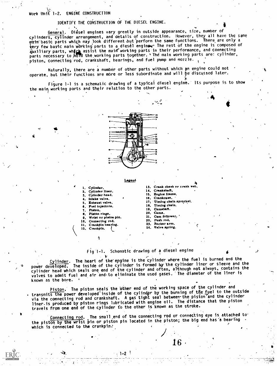
Figure 1-1 is a schematic drawing of a typical diesel engine. Its purpose is to show
the mail working parts and their relation to the other parts.
Cylinder. The heart of the'epgine is the cylinder where the fuel is burned and the
poWer developed. The inside of the cylinder is formed by 'the cylinder liner or sleeve and the
cylinder head which seals one end of the cylinder and often, although not.always, contains the
valvet to admit fuel and air and-to eliminate the used gases. The diameter of the liner is
known as the bore. v
6
Piston. The piston seals the other end of the working space of the cylinder and
transmits the power developed'inside of the cylindpr by the burning of t4elyel to the outside
via the connecting rod and crankshaft. A gas tight seal between-the piston and the cylinder
liner-is produced by piston rings lubricated with engine oil. The distance that the piston
travels from one end of the cylinder to the other is known as the stroke.
Connecting rod. The small end of the connecting rod or connecting eye is attached to
the piston by the wrist Pin or piston pin located in the piston; the big end has'a bearihg
which is connected to the crankpin:
1 6 .
. - #Crankshaft. The crankshaft obtains its rotary motion from the piston through the
connecting rod and crankpin located between the crank webs or crank cheeks. The work of thepiston-is transmitted to the drive shaft. A flywheel of sufficient files is fastened to thecrankshaft In order to reduce speed fluctuation by storing kinetic energy during the periods .
when power is developed and giving it back during the other periods. o
. , __.
Camshaft, A camshaft is driyen from the crankshaft by a chain driA. or by timinggears. Through cam followers, push rods, and rocker arms, the intake an.d exhaust valves areopened by cams on the camshaft. Valve springs serve to close the valves.
Crankcasq. A crankcase is constructed to protect the crankshaft, bearings, connecting'rods, and related parts, to catch the oil escaping from the bearings of the moving parts, and ,to provide a reservoir for lubricating oil. If the crankcase is constructed to support thewhole engine, it is called a bed plate.
Fuel pumps and nozzle. Fuel for diesel engines is delivered into the combustion spaceof the cylinder by an injection system consisting of a pump, fuel line, Ind injector, alsocalled the injection or spray nozzle.
EXERCISE: Answer the following questions and check yeur responses against those listed atthe end of this study ynit.
fir
1.. The heart of the diesel engine where the fuel is burned is known as the
a.. crankcase.b. cylinder.
c. piston.d., valve.
2. The crankshaft obtains its rotary motion fromthe piston through the
d. intake valve. c. timing chain.b. exhaust valve. d. connecting rod and crankpin.
3. The camshaft is driven from the by A chain drive or, timing chain.
a. fuel pump c. crankshaftb. piston d. cylinder
4. The part that transmits the power from the burning fuel'to the outside via theconnecting rod is the
a. piston.b. valve.
c. camshaft.d. cylinder.
5. The section of the engine used to keep the connecting. rod and the crankshaft welllubricated is the
a. cylinder.b. liner.
c. crankcase."d. crankpin.
6. Fuel is delivered to the combustion space by an injection system consisting of afuel line, injectors or nozzles, and the
a. camshaft. c. crankshaft.b. connecting rod. - d. fuel pump.-
7. The big end of thecrankpin.
a. crankshaft c. camshaftb. connecting rod d. piston
has a bearing which is connected to the
Work Unit 1-3. ENGINE CLASSES.
IbENTIFY THE FIVE DIESEL ENGINE CLASSES
Diesel engines may be divided into five classes using differ'ent bases for thedivision. These five classes are the: operating cycle, cylihder arrangement, piston action,method of,fuel injection, and speed.
Operating cycles, Diesel engines can be divided into two groups based on. the numberof piston strokes per cycle, in (1) four-stroke-cycle, or, for---Wort, four-stroke engines ,- and(2) two - stroke - cycle., or two-stroke engines.
Cyl in derV arrangement
Cylinders-in-line. This is the simplest arrangement with all cylinders parallel , inline, as shot;"n in figure 1-2. This construction is used for engines having up to 10 cylinders.
4
T
1 ,4;1,..
Fig 1-2, In-lin engine. \\. . .
V-arrangement. If an engine has more than 8 cylinders, it becomes di fficiult ti) make a rsufficiently rigid frame and crankshaftewith an in-line arrangement... The .
V-arrangement' (fi g 1-3a ), with two connecting rods attached to each crankpin ,- permi tsreducing the engine length by one-half, thus making it much more rigid with, a stiffcrankshaft. This is a common arrangement for engines with- 8 to 16 cylinders.Cylinders lying in one plane are called a bank. The angle between the banks may varyfrom 30° to 120°, the most million angle being betwten-40° and,,75°.
61)
Fig 1-3. Vee-type engine.fL"
401
Flat engine. The flat enginejfig 1-3b) is similar to 'a V-engine with an angle of180°' between the banks. This Arrangement is used mostly for trucks and buses.
Mul tfple-engine units. In order to increase the engine power without increasing itsbore and stroke, two or four complete engines, having six or eight cylinders each, areconfined in one unit by- connecting each engine to the main drive shaft 5 (fig 1-4a and1-4b), by means of clutches and gears or clutches and roller chains. Figure 1-4ashows a twin-engine and figure 1-4b shows a quadruple-engine or quad.
1 - 4
rep
(el
' Fig. 1-4. _Mul§tiple7unit engines.Th A /
Vertical-shaft engines. recent development is an engine with four connecting rodsattached to one crankpin ig 1-5)% The four cylinders are all in one horizontalplane, the crankshaft thus being vertical. Four banks located one on top of the otherand using one crankshaft with four cranks fOrm a compact 16-cylinder engine,under thename of the pane* engine. . ,
,7
Fig A-5. T9piriew of pancake engine.
Piston action
Single-acting engines use 'only,one end of the cylinder and one face of the pisto'for the development of power. Nearly all diesel engines are single-acting.
Double-acting engines use both ends of the cylinder and both faces of the pistonfor the developmeht of power. Double-acting engines are built only in large andcomparatively low-speed units. Ak
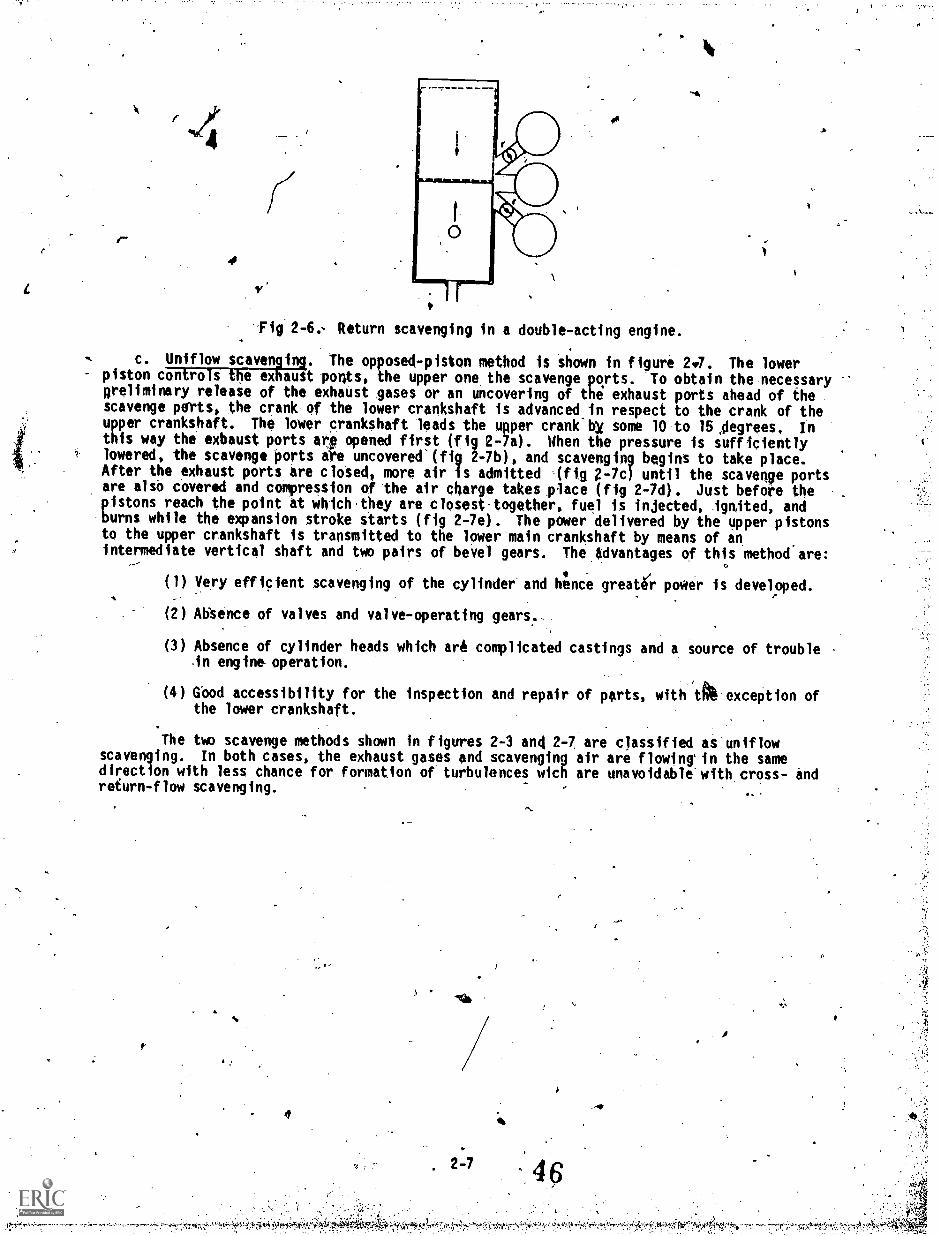
Opposed-piston engines are engines having two pistons per cylinder driving twocrankshafts. Th4$ design presents many advantages from the.viewpointofcombustion of fuel, engine maintenance, and accessibility of all parts except thelower crankshaft.
Fuel injection:' Diesel engihe are divided into air-injection engines and solid or,mechanical-injection engine's. The meaning of these terms and the differences between thesetwo types are-discussed in Study Unit 3. Therefore, atilthis time, 0 need only mention thatair-injection engines are gradually disap ring.
Speed. All diesel engines can be ivided into three classes in reltition to speed;low-speed, medium-speed, ancl-Kigh-sked.- The present trend is away from low- and evenmedium -speed engines and toward increasingly higher speed engihes.
EXERCISE: Answer the following questioni and chgck your responses against those listed atthe end of this study unit?
1. Diesel engines can be divided into twogroups'based pn the numberof per cycle.
.a. valvesb. injeCtions
1-5
c. piston strokesd. turns of crankshaft
0
1.
2. The s4mplest arrangement of having all cylinders parallel is known as
a. tn-ine. . c. flat-engine.b, ,vertical-shaft. d. pancake.
3. In order to increase-the engine power without increasing its bore and strokea(n) e ermine is used.
a. in-line c. multipleb. vee-type d. pancake
4. Engines ring only one end of the cylinder and one face of the piston are said tobe .
a. double-acting. c. stationary.b. singlk-acting. d. low-speed.
5, Diesel engines' fuel systems are divided into air injection or
a. solid injection. c. mechanical injectiobit liquid injection. d. hydraulic injection.-
6. All diesel engines can be divided into three classes for speed.
a. 1st, 2nd, and 3rd.b. low, mediqmind high.c. low, evenOnd higher, .
d. in-line, vee, and pancake. 1
se clases- are
7. The five classes'of diesel engin4s are operating cycle, speed,. fuel injection,cylinder arrangement, and
a. weight.b. piston-action.
Work Unit 1-4. ENGINE MEASUREMENTS
IDENTIFY BOI AND STROKE:
IDENTIFY PISTON DISPLACEMENT.
c: alinement of valves.-d. four-stroke.
IDENTIFY VACUUM IN THE CYIINOER.
IDENTIFY VOLUMETRIC EFFICIENCY..
Bore and stroke. The size of an engine cylinder is usually indicated in terms of boreand stroke (fig 1-6). Bore is the-diameter of the cylinder. Stroke. is the distance they"
piston moves in the cylinder or the distance between top dead center and bottom dead center.
. When reference is made to these twO measarements, the bore is always giveh first. For
example, a 4.x 4 cylinder means that the cylinder bore, or diameter, is4 inches-and thelength of the stroke is 4 inches.
Piston displacement. Piston displacement is the volume of spaci that the pi.ston
displacei as it moves from bottom dead center to top dead center. The volume is figured by
multiplying length of stroke by the area ora circle-having the diameter of.the gglinderbore. Thus, a 4-inch diameter circle has an area of 12.566 square inches, and, therore,this times .inches (length of stroke) equals 50.264 cubic inches, the piston displaCement orthe number of cubic inches the piston displaces as it moves from bottom dead center to topdead center.
4
Vacuum in the cylinder. When the piston starts to move downward in the cylinder onthe intake stroke, it produces a vacuum in the cylinder. 0 both the intake and exhaustvalves are closed, then no substance could enter to fill this vacuum. The cylinder would
remain emptj. However, at the same time that the piston starts to move down, the intake valveis opened.' Now atmospheric pressure pushes air past the intake-valve and into the cylinder.The cylinder, therefore, becomes filled with air (or with fuel-air mixture in gasolineengines).
20
Fig. 1-6. Bore and stroke of an engine cylinder.
. Atmospheric pressure. The miles and rhile of air extending.abovg prestes downward orexerts pressure. Ordinarily, this pressure is not' noticed because we are accustomed to it.If the air was removed from A container and the container were opened, thisdressure would )
push.,air back into the container. ,This might be compared to what happens when an empty belilleis held under water and the cork is removed. Thd pressure of the water pushes water int her
bottle. The 'higher we go into the air, thf less pressure is found. The reason for tkisthat as.we ascend there is lets air abop us;:we climb toward the-top of the atmosphere. This
above the earth, for example, thetpressure itobout.4.4 psi. Returning.to earth, the ai?1,tmeans there is less air to press down on us arid, therefore, the pressure is less: Six mljes
pressure' increases. The nearer we bpproach fo earth or the bottom of the o,bean ofsair, the-greater the pressure of air :\ At sea level, this pressure is about-14.7 psi'. A
,Volumetric Ifficiency. Although the atmosphere exerts considerable prssure and
rapidly forces air into the cyliqder' on the intake stroke, it does take time for the air toflow through the intake system and past the intake valve.. If given enough time, enough airwill flow into tile cylinder to "fill it up." However, thg air given very littlelOpe to dothis. For exampTe, when the engine is running e 1,200 rpm, the intake stroke lasts-only0.025 second. In this very brief period,'all 'he lit that could enter does not have time to k /
flow into the cylinder. The intake stroke dA too quickly. Nevertheless, this factor has-
, been taken into, consideration in designin the engine so that good operation will result evenat high engine speed.
r
V
Measuring volumetric efficiency.- The measure of the amount of fuel-air mixtureactually enters the ylind r is referred to in terms of vo4umetric -
effiCienty. Volumetric e fici cy is the ratio between' the amount of fuel-airmixtdre that actually ent s the cylinder and the amount( that coulb enter Underideal conditions. The grey the volumetric effitiency,41the greatedthevountof fu -air mixture eftering the-cylinder;-and the greater t amount Ofofibl-airmixtueg, the more power is produced fromlpie engine cylinder. At low speeds, morefuel-air gixture can get into the tylindel, and the power 'pro uced during the.power stroke is greater. Volumetric efficiency is high, but at high speeds, the
jhen is 1 wer. In addition, the air,shorter time taken by the intake stroke redUces the amount of fuel:airmilaneentering the cylinder. Volumetric efficiencyis heated as it passes through hot manifolds on its way to the Cylinder,, and\itexpands. This further reduces the amount of fuel-air m.ture entering thecylinder and further reduces volume is efficiency. .
,
V
N.,17
tr
Increasing volumetric efficiency. Volumetric efficiency is'higher at low engines speed because more fuel-air mixture gets into the cylinder. Volumttic efficiency
can also be improved by use of a blower or air-compressing device. On gasolineengines, this device'ls called ek supercharger. It raises the air pressure ab9veatmospheric pressure so that the air is pdshed harder on its way into thecylinder. The hai.der push, or higher pressure insureshit more 'air will enterthe cyllinder. In a supercharged engine, the volumetric efficiency can run wellover 100 percent. .Since 100 percent efficiency means that the pressure inside thecylinder equals atmospheric pressure, a'volumetric efficiency of more than 100percent means thqt
0retsure inside the cylin er would be greater than atmospheric
WIpressure at the rid theintake-stroke. This increased volumetric efficiencyincreases engine power output. A superc rger is very important on airplaneengines because the lowered air pressure (about 4.4 psi at a .height of 6 miles)must be greatly increased.if engine power output is to be maintained at highaltitudes. Also, on 2-stroke-cycle engines, some form of.device is required toincrease the pressure of the ingoing fuel-air *mixturf,
cell,
EXERCISE: Answer the following questions and ch ck your responses against those listed at
4
I
4
1
the end of this study unit.
Bore is the size of the
t. .end of the piston.stroke.
. Stroke is the idi ,!
a. diameterot the cylinder.. _distance between TDC.pnd BDC.
c. length of the piston rod.. 4 &Vance between the crank and TDC.
,-1K I
miume of space that 'thee piston displaces frOm
stroke. ,' c. bore,
vacuum in'the cylinder. d. piston displacement.piston
en he piston istarts.to move downwai-d in the cylinder on the
1
3.
c. diameter of the cylinder.d. distanct the eton moves. ,
f
,"
49r
BDC to TOC is called
produ es
a.-..pitton displacement.b. bore and stroke. '
c. vacuum in the cylinder.d. ignition of fbel.
5. At lower speeps, the volumftl.ic eff)icy is
c. low.d. fluctuating.
incre4sed by using a
c. blower.d. heavier piston.
a. higher.b. ,not changed.
6. Vo/letric efficiency can beVI
a: larger engine.b. smaller engine..
Mork Unit 1-5. ENGINE OUTPUT
Or
DEFINE WORK.
DESLRIBE ENERGY.
DEFINE POWER.
IDENTIFY THE DYNAMOMETER.
IDENTIFY TORQUE EFFECT.
IDENTIFY TORQUE-RORSEPOWER-SPEED RELATIONSHIP.
4
intake stroke, it
V
,
Engines vary in size and output. To Compare engines , compare not only their'sizejbut also the work they are capable of doing. These functions are explained below.
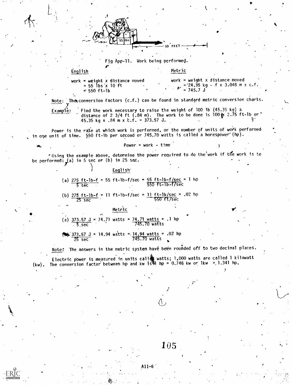
Work. W2rk is the movement of a body against.lan opposing'force. When a weight islifted from The ground, work'is done on the weight. It is moveO upward against the force ofgravity. When a tank pushes over a tree, it does work on the tree a it forces its to theground. If a 1-pound weight is lifted one foot, one foot-pound of wok is done.
Energy. Energy is the ability ,to do work.' As,the spged a tank is increased,the energy of movement of the tank increases. It can-thereby knock ovt a tree more easily.The higher a weight is lifted from the ground, theflore energy.is stored.in the weight. Then,
when it falls, it will strikethe ground'harder; that is, it will do more work on the ground.Suppose a stake is being driven in the ground: The greater the distance the weight fails, thempre work it does on the stake and the farther tt drives the stake into the ground.
Power. Power is the rate of work. It takes more power to work quickly than to .work slowly.--174ines are rated im terms of the amount.of work they can do per minute. ,Alarge engine that Can do more work per minute is more powerful than a smallengine whichcannot work as hard. The work capacity of engines is measured in horsepower. A horsepowerisa definite amlghi of power. Actually, it is,the amount of power that ,an avenge horse wasfound to generate when working hard. The tests measuring horsepower were made many years agolat the, ime steam engines were being developed. It was found that an average horse could pulla weight of 200 pounds a distance of 165 feet in 1 minute. The amount-of mark invOlved hereis 33,000 foot-pounds (165 times 200). If 100 pounds were lifted 330 feet, or if 330 poundswerejifted 100 feet the, amount of work would be the same, 33,000 foot-pounps. When this
amount of work is 'do le 1 minute, then 1 horsepower is required. If it ffpk 2 minutes to do
t is amount of work, then 16,500 foot-pounds per minute, or 1/2 hp, would be required. Or if
33,000 foot-pounds of work were done in 1/2 minute', then 66,000 foot-pounds per minute, or 2hp, would be required.
Prony brake. A prony brake may be used to Measure tffe actualhousepewer that.anengine can delives. 'This devicerusually makes use of a series of wooden blocks fitted arounda special flywheel that is driven by the engine (fig .1-7). A tightening device,is arranged so
the blodli can be tightened on the flywheel. In addition, an arm is attached to thistightening device and one end of the arm rests on a scale. In operation, the wooden blocks
are tightened on the flywheel. This loads up the engine and works it harder. Also, theressure.on the blocks tends to cause the arm to turn so that force is exerted on the scales.he gth of the arm times the force e rted,on the scales gives the ingine torque in .'
you eet. The results of the prony brake test can be converted into brake horsepower by
usi g this,formula:;r--
Bhp =233,000
whee 1 is length of the arm in,feet, n is the speed in rpm, and w i(the load in pounds .on
the scale. For example, suppose the arm is 3 feet long, the load on he scale is 50 pounds,,
and the_speed is 1,000 rpm. - Substituting in the formuli gives:
Bhp 2 k 3.1416.x 3 x 1,000 x 50 = 28e56 brake horsepower33,000
\
.r
Ff
r
Fig. 1-7. Simplified drawing of a prony brake.
1-923
or
ti
4
4
,
Dynamometer. The dynamometer Is essentially-a dynamo of a special type which canbe driven by an engine. This special dynamo can absorb all the power the_engine can produceand indicates this power on dials or gages. Although the-dynamometer is more complicated thana protly brake, it is generally,considered to be more accurate. In addition to-measuring engine power output, the dramometer can also be used to drive the engine forpurposes of.measuring the friction bf the engine itself or of the various accessories.
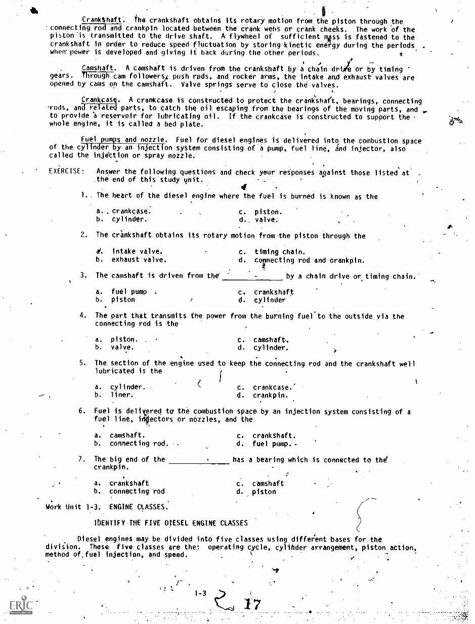
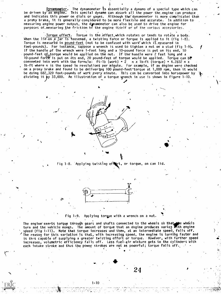
Torque effect. Torque is the .effect.which rotates or tends to rota te a body.When the lcd.on a jar is loosened, a twisting force or torque is applied to it (fig 1-8).Torque is measured in pound-feet (not to be confused with works which i.mgasured infoot-pounds). For instance, suppose a wrench is used to tighten a nut on a stud (fig 1-9)..If the handle pf the wrench were 1-foot long and a 10-pound force is put on its end, 10pound-feet oh,torque would be applied on the nut. If the'handle were 2 feet long and a10-pound for' is put on its end, 20 pound-feet of torque would be applied. Torque can btoconverted into work with the formula: ft-lb (work) . 2 n x lb-ft (torque) = 6.2832 n xlb-ft where n is the speed in revolutions per minute. For example, if an engine were checkedon a prony brake and found to be delivertpg 100 pound-feet-torque at 1,000 rpm, then it wouldbe doing 682,320 foot-pounds of work every minute. This can be converted into horsepower bydividing ityy 33,000. An illustration of a torque wrench in use is shown in figure 1-10.
444°
it
C-
.4k
Fig 1-8. Applying twisting of 'it, or torque, on can lid.
1.
Fig 1 -9. Applying torpe with a wrench on a nut.
The engine'exertt torque through gears and shafts connected to the wheels so thatiae wheelsturn and the vehicle moves. The amount of torque that an engine produces varies ;Pith engine
speed (fig 1-11). Note that torque increases-and then, at an intermediate speed, falls off.The reasog, for this variation is that, .with increasing speed, the engine is turning faster andis trills capable of supplying a greater twisting effort or torque. NoWever, with further speed
increases, volumetric efficiency falls off. Less fuel-air mixture gets to the cylinders witheach intake stroke and thus the power strokes are not as poWerful; torque falls off., .,
ft-
J
31
AO
1.
4'
IA
Fig 1-10. Tcfrque wrench in use, tightening main bearing studs of an engine.'
4
asa
220
,4RPM IHUND1111)11
Hg 1-11. Relationship between torque and speed.
Torque-horsepower speed (rpm) relatioship
Figure 1-12 shows the comparison between the horsepower and torque of an engine.Torque increases with speed (up to rated speed) as shown in figure 1-11. Horsepower also
shows a change with speed, and this is more marked than with torque. Horsepower is directly
refated to both, torque and speed. When both torque and speed are on the increase, as in thespeed range of 1,200 to 1,600 rpm, then horsepower goes up shtrply. When torque reachesmaximum and then begiAs to taper off, the horsepower curve starts to drop. Finally, in thehigher speed ranges when torque falls off sharply; horsepower also falls,off. The horsepower
formula Hp = 2 lnw given above shows that horsepower depends on both speed and torque, sinoe
torque equals w and is n is speed. ,Substituting the formula and dividing 21r (or 6.2832) into
33,000 gives:
Hp = torque x rpm.5,252
which shows t4e,relationihip between horsepower, torque, and speed more directly.
A rated speed is indicated in figures 1-11'and 1-12. This is the speed at which
the governor is usually .set-in military vehicles. The rated speed is selected 'because, at
higher engine speeds, wear on the engine increases. rapidly and a disproportionate amount of.
fuel is used. Overspeeding or driving the engine above rated speed, only allows a slight
increase of horsepower.
1-11 25
44p,,
L
..EBROMPASSIWN..., g "-"-mit....am =
airrik1.l1mo
l 1a1111i
I1l1111
1-1I"1
tonwol1lr./4 11
mMN
milimmuIN
11111111111111111
1.1Imini1.
U1444 41444410144V
Fig.1711. Retetionship between torque and horsepower..
Gross andlnet horsepower. The.gross horsepower of an'engine is the amount ofpower the engine delivers before any accessories have been attached. Net horsepower is thepower available at the flywheel after all accessories ate attached.
Indicated horsepower. Indicated horsepower is the horsepqwer, actually developed"inside the engine cylinderi. It is callq# "indicated" horsepower
pressuresan indicating device
is required to measure this horsepower. 'This device measures the ioressures developed in the
ticated horsepower is always'considerably greater'than horsepower delivered by the engine .
ine cylinders and, by a series of steps, translates this data into indicated horsepower.
because power is lost from the engine in a number of ways .1fTiction,heat-loss, etc.).
,SAE horsepower. The Society of Automotive Engineers (SAE) developed a simplifiedmethod of calculating horsepower based on engine dimensions. This rating was used only forcommercial licensing of vehicles. This formula is:
ONHp
where D is the cylinder diameter in inches and N is the number of cylinders.
EXERCISE: Answer the following questions and check your responses against those listed atthe end of this study .unit.
1. Work is define'd'as
2. Energy is described as when the speed of a tank is increased
3. Power is defined as
4. If a 10-pound weight_is lifted 6 feet in the air, then , foot n sof work. is done. 7
a. 30b.. 10
c. .60d. 6
5. The item that is essentially a dynamo of a special type which can be driven by anengine is called a
a, prony brake. c. torque effect.b. dynamometer. d. .horsepower,
6.. The effect that rotates or tends to Totate a body is called
a. dynamic torque effect.b. torque-horsepqwer-speedrelationship.c. tqrqiie-speed relationship.'
0.1 torque and horsepower relationship.
Work Uni l.6 ENGINE EFFICIENCY '
IDENTIFY ENGINE EFFICIENCY.
4 The term efficiency means the relationship between results Otained and the effortrequired to obtain those results, It is ;expressed as: efficiency = output. Suppose, fpr
input
example, a set of pulleys were used,to raise a 270-pound weight 2,feet and this required al00-poinid pull for 6 feet (fig.1-13). It would take 600' foot-potinds to get mit 540
foot-pounds. The ratio would .be 540 or0.90. In other words, the-efficiency (of the pulleys
600 $ .
would be 90 percent. There would be a loss of 10 percent of the' work put%in. The system of
pulleys shows a loss (or is only 90 percent efficient) tacause of friction. No machine otengine is 100 percent efficient; all lose energy as explained below.
1'
A
Fig 1-13.
I
SyStem'of pulleys' inovbich 600 foot-pounds must be expended to realize 5410foot-pounds of work'.. N, .
--'414)11q4,41*.04-44115**P14-4.-
-;(
tar
Friction loss. Friction is a source of energy loss in any mechanical sytem. If
a heavy plank is dragged across a rough floor, it offers some resistance to the movement.This resistance to movement would be less if the plahk and floor were pblished smooth.Resistance would be still less if the plank floated in water. This resistance to movement iscalled friction. Friction Can be visualized as being caused by tiny irregularities, or highpoints, in the surfaces of the moving objects. These catch on each other and particles aretorn off. All of these require force to overcome. If the plank and floor are made smooth,then the projecting points are much smaller and have less tendency to catch and tear off.Therefore, less force is requited to pull the plank across the floor, and,if the plank isfloSted ih water, the surfaces can.no longer rub against each other. There is, however,. still
'some friction in the liquid. In the engine, friction occurs at all moving part, even thOughthe parts are,in effect, floating in films of oil.
Mechanical efficiency. The mechanical efficiency of the engine is therelationship between the power developed in the engine cylinders (indicated horsepower) andthe power delivered by the engine (brake horsepower). Internal engine losses from frictionand other factors always prevent brake horsepower from equaling indicated horsepower. A
typical engine, for example, might develop 200 indicated horsepower as against an actual brakehorsepower of "180. This engine would have a mechanical efficiency of:
Brake horSepower 180 ,
Indicated horsepower 2 200 2 90 perc
.. Thermal, efficiency. The definition of thermal efficienc is the relationshipbetween the heat energy in the fuel and the engine power output (thermal means of orpertaining to heat). The term "thermal efficiency" relates to the heat energy of'the fuel and
pthe work; output. The heat energy is the amount of heat the fuel will produce a 4r4 t burns.Much of this, heat is lost to the cylinder walls and cooling system. Still mo is lost in the
hot exhaust gases as they pass out of the cylinder. This heat than is lost cannot do anythingto cause the engine to produce power. Therefore, only a relatively small part of the heat inthe burning fuel can.contribute anything toward pushing down on the pistons and therebycausing the engine to produce power. In actual practice, because of the great amount of heatlost to the cooling water and lubricating oil and'in the exhaust gases, thermal efficiency maybe as low as ZO percent. In other words, as much as 80'percent of the energy in fuel-islost. However, the remaining 20'percent is sufficient to operate the engine normally.Practical limitations prevent thermal efficiencies of much above 25 percent.
The overall thermal efficiency of an engine is the relationship between the fuelinput and the power output. This relationship is commonly expressed in heat units calledBritish thermal units (Btu). One Btu is equal to 778 ft-lbs of work; therefore, thehorsepoweroutput of an engine can be' readily converted into Btu per unit of time. The source
of power in an engine is fuel, and the Btu content of regularly used fuels has been determinedby laboratory analys'is: ,
Thermal efficiency ...power output in Btufuel input in Btu
Example: An enline-delivers 85 bhp for a period of 1 hour and in that time. consumes 50 pounds (approx 7 /2 gals) of fuel., Assuming that the fuel
has a value of 18,800 Btu per lb, we find the thermal efficiency oftheengine:
Power delivered by the engine is 85 bhp for 1 hour, or 85 hp-hours.
1 hp-hour =
33,000 ft-lb per min x-60 min778 ft-lb per Btu
= 2, 545
85 Bhp.x 2,545 Btu = 216,325 Btu output
'50 lb x 18,800 Bty per lb . 940,000 Btu input per hour.
Overall thermal efficiency = 216)325940,600
0.230 or 23 percent
,28
A
EXERCISE: Answer the following questions and check your responses against thoS'e listed atthe snd of this study unit.
1. The relationship between results obtained and the effort required to obtain those.results is known' as engine
a. operation.b. accuracy.
C.
d.
efficiency.
friction.
A 2. Three ways that a machinetwill lose efficiency are:
a.
b.
c.
Work Unit 1-7. THE MAIN STATIONARY PARTS OF THE DIESEL ENGINE
IDENTIFY THE FUNCTION OF THE MAIN STATIONARY PARTS OF THE DIESEL ENGINE.
DESCRIBE THE CYLINDER HEADS.
1
General. The main stationary parts of a diesel engine are designed to maintainthe moving or working parts in their proper relative positions, so that the gas pressureproduced by the combustion is effectively used to push the piston and rotate the crankshaft.The main requirement is strength, next comes low weight, and finally simplicity of design.Diesel engines that were built a few years ago were several timesas heavy per horsepoweroutput as the more modern engines'. The reduction in weight in recent years has been possibledue partly to the improvement in Oaterials which proAdes greater strength per unA.area, but ".
mostly due to improved design and methods of calculation and manufacture which permit,the'useof lighter sections. lh
Engine frame. The frame connects the top of the cylinder to the.supports for the
crankshaft. In the earlier designs (at present used only'in large, low-speed engines), theframe consisted of a separate cylinder block, crankcase, and bed plate with an oil panor sump(fig 1-14). The main bearings, seppn-ting thy crankshaft, were held in the crankcase, whilethe pistons operated sin- he cylinder block above it. The gas-pressure load was taken up by
tie bolts running from top to bottom. Cylinder block; crankcase, and bed plate were made of .-
gray -iron castings.
CYLINDER
/NA('CRANK CASE
TIE *OLT
EED PLATE
Fig 1-14. Engine frame with tie bolts.
Modern desig of high-power output engines gave frames of welded steel withplatet Ilbcated at places here the loads occur (fig 1-15). The customary arrangement combines
th cylinder biotic end of pan with the main bearing supports, although a separate crankcaseSalon is sometimes used. Cylinder blocks and crankcases of.small high -speed engines are
still made of cast iron. .,4
4
s,t54:7;
1-15 29
The crankcase is often integral with the cylinder block. In the models where itis a separate section, it generallylconsists of a plain rectangular frame with cross-ribbingto provide rigidity,., Occasionally, the main bearings are held by a cross-ribbing in thecrankcase, but more,often they are hung from'the bottom of the cylinder block. Access dooriare provided at every cylinder to permit assembly and observation of the bearings.
cylinders And cylinder liners. The cylinders were separate units on some oldermodels, butjn modern, engines they are secured within the block which alsoiontains plssagesfor cooling water, lubricating oil to the bearings, and intake air. Each cylinder is securedin a separate compartment with crossbracing between the compartments.
Fig 1-15. Sectional sketch of welded frame.
Dry liner. The dry liner is a simpA sleeve with thin walls inserte0 in the
cylinder block (fig 1-16). The cooling water moves about the outer cylinder and
does not touch the liner. The liner is inserted in the cylinder with a light
press fit. When worn or scored,.it can easily be removed and replaced by a new
liner.
R
Fig 1-16. Dry liner..Wet liner. The wet liner is a sleeve whose
contact with the -Cooling water (fig 1-17).water leakage at the top end by a gasket unby 'rubber or neoprene rings around the lower e
contract lengthwise. The thickness of the wallworking pressure of the gases.
( .
er surface comes into directThe liner is normally sealed against
the flange or.a machined fit, andThe liner is free.to expand or
s such as to take the full
0
J. 30
, . .:
Wet jacketied liner. The liner has its own cast-on or permanently shrunk-on jacketi
around-the Optside for the circUla ing cooling water (fig 1-18). The water is
iadmitted into the bottom of the ja et and leaves through the top. This typeisused mostly in two-stroke engines ere it is difficult to obtain a watertightseal around the ports when using a wet liner because of the expansion of the linerdue to heat during engine operation.
a
The cylinder liner mulX be made of material which will enable the piston-and rings to move up and down with minimum'friction and will give the least wear to both theliner and the piston parts. Cast iron is the usual material, although steel'sleeves aresometimes used. A recent development has been a coating of 0.003- to 0.006- inelectro-deposited porous chromium. The chromium resists wear, while the pores in the platinghold lubricating oil and maintain a lubrication film necessary to reduce friction and scoring.
m.
CI
Fig 1-17. Wet line
( '
Fig,1 -18 Water jacketed liner.
1-17 31
I
t,
Cylinder heads. The cylinder head seals the combustion chamber and, to mostengines, tontains'the.valves and passages for intake and exhaust gases, the fuel injectionnozzle, the air starting and relief valves, and passages for the cooling water from the ,
cylinder jacket as shown in figure 1-18. It is a casting alloy iron, seldom made ofaluminum. Because of the heat passing through Me cylinder head from the combustion chamberand the exhaust passageS, it has to be water-cooled. Such cooling prevents excessivetemperatures which might crack it and which would interfere with the operation of the fuelinjection nozzle and all other valves. The larger-bore engines have individual heads for eachcylinder, while small-bore engines may have a single head covering all cylinders or pairs ofcylinders.
Other parts. In older designs and in very large, low -speed diesel engines, themaih and crankp(n bearings consist of heavy cast-iron or cast-steel boxes with a thick, up tOone-half inch, babbitt lining: Each bearing Must be hand-scraped to a running. fit with its.journal. All modern diesel engines, regardless of size and speed, have precision. bearings.Precision bearings are separate from the saddles and connecting rods. They consist ofrelatively thin steel, bronze, or brass-shells with a lining of bearing metal which isgenerally 1/32-inch or less in thickness. The bearing metal may be one of several types whichhas proved satisfactory: lead-base babbitt, copper-lead, or cadmium-silver. Grooving is keptto the minimum, and wedge-type lubrication is used to the fullest extent.
Double - acting diesel engines require a crosshead and crosshead guide. The purposeof the crosshead guide is to take the side thrust coming from the'angularity of the connectingrod,"hich otherwise would be taken by the cylinder liner. The bearing surface of the .
cross ead guide is a flat slipper. Bearing loads are low and, with proper lubrication, anordin ry babbitt usually suffices as a bearing surface.
EXERCISE: Answer the `following questions and check your responses against those listed atthe end of this study unit.
1. TIe main stationary parts of the diesel engine are designed to maintain theworking parts or moving parts in
a. the crankcase.b. lubricating oil.c. proper relative positions.d. and out of the engine.
2. 'Describe the cylinder head.
Work Unit 1-8. THE MAIN MOVING PARTS OF THE DIESEL ENGINE
STATE THE MAIN FUNCTIONOF THE CRANKSHAFT.
STATE THE PURPOSE OF THE PISTON.
IDENTIFY THREE PURPOSES OF PIStON.RINGS.
IDENTIFY THE PURPOSE OF THE CONMCTING ROD.
IDENTIFY THE FUNCTION OF THE CAMSHAFT.
Crankshaft. The main function of the crankshaft is to transform the reciprocatingmotion of the pistons into rotary motion. The forces actingsee a diesel engine crankshaft arehigh because of the high peak gas loads and the inertia forces of the moving parts. The mainrequirements are mechanical strength-anelengthwise.and torsional rigidity. The shafts haverelatively large diameters and are supported by main bearings between each pair of cranks asshown in figure 1-19. At present, .most crankshafts are forged, some from .open- hearth but themajority from high-strength alloy steels. However, advances in understanding the stressdistributions in diesel crankshafts are..changing the situation. It has been found that theremoval of metal at certain sections will redistribute the stresses and result in a strongershaft. Casting permits easier application of such improved shapes. As a result,
v32
high-strength cast-iron and, In some cases, cast-steel crankshafts are being used In severalmodern dieser,edeineS. Many forged steel shafts are surface- hardened by electrically heatingthe surface ilOne and quenching it with sprays of water. Surfacing of the journals with a
harder metal, such as electro-deposited chromium which will take smooth dense finish, isbeing considered to reduce shaft wear and improve bearing conditions. The shafts are drilled
through the crank _webs to admit pressure lubrication frOm the main bearings to the crankpinsand wrist pins, In some cases, the oil is carried farther and is used for cooling the piston
crowns.
..i.Jualc /Ai dr 1111!1(11:out
Fig 1-19. Crankshaft of a'six-cylinder diesel engine.
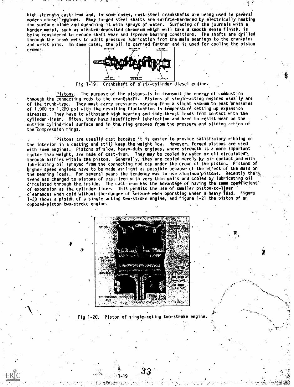
Pistons. The purpose of the pistons-iS to transmit the energy of codibustionthrough the connecting rods to the crankshaft. Pistons of single-acting engines usually are
of the trunk-type. They must carry pressures varying from a slight vacuum to peak 'pressuresof 1,000 to1,200 psi with the resulting fluctuation in temperature setting up expansionstresses. They have to withstand high bearing and side-thrust loads from contact with the
cylinder-liner. Often, they havesinsufficient lubrication and have to resist wear on theoutside cylindrical surface and in the ring grooves from the pressure.and sliding action of
the compression rings.
Pistons are usually cast becadse it is easier to provide satisfactory ribbing onthe interior in a casting and stil) keep.the weight low. However, forged pistons are used
with some engines. Pistons of ^slow, heavy-duty engines, where strength is a more important
factor than weight, are made of cast-iron. They may be cooled by water or oil circulated)
through baffles within the piston. Generally, they arg cooled merely by air contact and withlubricating oil sprayed from the connecting rod cap under the crown of the piston. Pistons of
higher speed engines have to be made aslight as possible because of the effect of the mass onthe bearing loads. For several years the tendency was to use-aluminum-pistons. Recently the
trend has changed to pistons of cast-iron with very thin walls and cooled by lubricating oil
circulated through the. inside. The cast -iron has.the advantage of having the same coefficient'
of expansion as the cylinder liner. This permits the use of smaller piston-to .rlinerclearances when cold yithout the danger of "seizure when operating under a heavy load. Figure
1-20 shows a bistdn of a single-acting two-stroke engine, and figure 1-21 the piston of an
opposed-piston two-stroke engine.
clk
"-4'.41,1.:;=*14.*:"
I '
togf;.;14. '474441;:,
Fig 1-20'. Piston of single-acting two-stroke engine.
Fig 1-21. Piston of opposed=piston two-stroke engine.
PistonS for use in double-acting engines are built up of several sections and areclosed at both ends because both ends Are used for combustion chambers. They are cooled byoil entering. and leaving through the piston rod.
Wrist pins. All of the,load developed in the cylinder passes through the wrist orpiston pin. It Ts the only connecting link between the piston and the connecting rod. Mostwrist piston are supported at both ends by bronze bushings in the piston bosses and aremaintained in place by caps which are fitted to each side of the piston. The connecting rodswings on a bronze bushing or needle bearing at the center of the pin. Such wrist pins areknown as full-Ulloating pins. In some engines the wrist pins are locked in'the piston at theends and are known as stationary pins. The disadvantage of this design is that all swingingmovement is confined to the connecting rod bearing and there is some Sanger of less uniformwear. A third type, a semi-floating pin, is supported at both ends by bronzerhings.in thepiston bosses and is clamped in the middle. in the connecting rod end.
Wrist-pin bearings operate under rather severe conditions. In addition to thegreat load from the. piston pressure, there is the handicap of less efficient lubricationbecause the swinging motion does not help. to form an oil film as much as the rotary motion ofa journal. The wrist pin is made of a steel alloy of sufficient strength to carry the loadand mktst have a fine-finish hardened surface to obtain good bearing action.
Piston rings. Afthe top of the piston are several compression rings which servethree purposes: 0
They seal the space between the piston and the liner thus prevening thehigh-pressure combustion gases, or the air charge during the compression
stroke, from escaping down the liner.
They ransmit heat from the piston to the water-cooled cylinder liner.
They dam art of the fluctuations of the piston side thrust.
The oil- scraper or oi-control rings usually are located at the-bottom end of the .
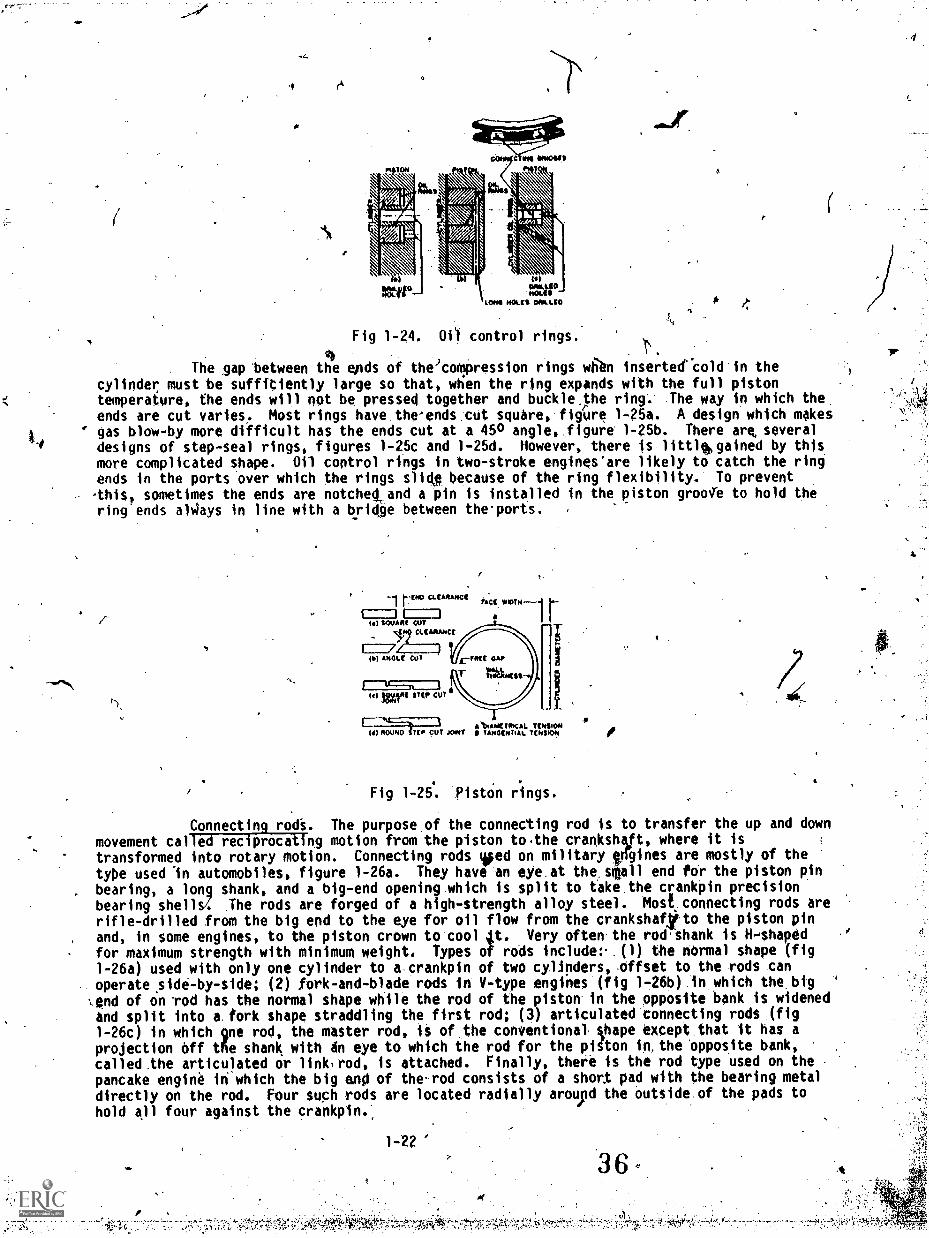
piston; in some engines they are place above the wrist pin. Small engines use one; largerengines use two or three oil-control rings to a piston. Their pOrpose is to scrape.off 'mostof the_lubritating oilsplashed upward by the crankshaft and connectingTod, thus reducing theamount of oil carried upward and burned in the combustion chamber. At the same time, theymust allow sufficient oil to be carried to the upper part of the liner during the upstroke, sothat there will be proper lubriCation for the piston and the compression rings._ Double-actingpistons.bave no oil-scraper rings as no oil is splashed on the liner.
Compression rings are made of gray cast -iron. Some types have special facings,such as a bronze insert, figure 1-22a, or 'a treated surface, to facilitate seating-in to theliner. To expeditethe wearing inor seating of the ring face, some rings have a'slightangle, 1/2 to 1 degree to the face, so that at first the contact area is very small, wear israther fast, and later decreases.
.1-20
1
410+.9 SCIA mut
(4)
111144TALIMM
(b)
A
Fig 1-22. Compression piston rings.
The type-4 compression ring most widely used has a rectangular cross-section.The diameter of the ring is slightlyiarger than the cylinder bore, and part of the ring iscut away to permit it to go into thtr cylinder. The diffvence in diameters produces a
'pressure against the liner wall. The pressure of thb tipper rings is increased by theadditional action of the gases. The combustion gases or compression air enter behind the ring
"through the vertical clearance which always exists between'a ring and its wove and force thering against the cylinder liner.
Sq.* engines,have compression rings with the bottom wall ,or both bottom and ppwalls beveled, making the ring thinner at the inside than on thd outside diameter (fig 1-23).The groove in the piston is machined to the same shape. The gas pressu e acting on the top
wall, due to the beveled, bottom surfact, produces an additional force p essing the ringagainst the cylinder walliand helps to seal it. On the otheeo hand, at e ch reversal of the
side thrust of the piston; the ring.slidesslightly'into the groove, is essed against the
upper groove wall, crushes the carbon which is deposited on0it, and keeps the ring from
sticking. Some engines use bt-metal rings, figu 1-22b, in,which the cas -iron wearing faceis brazed to a steel inner ring to obtain increa ed strength andlo reduce the probability of
ring fracture. 0 4
....
MANUAWALL -
CVLMKWAWALL
pfslicctti). 41),44
(a)
(iousLc
t&ITOLNL
(b)
Fig 1-23. Bevelled piston rings.
The oil control rings have a narrow face so as to obtain a higher unit wallpressure andiare often undercut to give a scraping edge. Some-engines use flexible rings
which follow the deyiations in the cylinder liner bore. Ln some designs the ring has one, in
others two narrow scraping edges, and the piston has rows of holes drilled-in it for draining
the oil through the bottom of the ring grooves or..throughthe lands between the grooves or
both (figs 1-24a, b, and c). The oil scraped bylthe ri back into its groove And stop the
scraping action. it is important that the.drainage fro he piston grooves be complete.
Inadequate drainage means faulty scraping, higher lubri _ting oil consumption, and a darkeit
color of the engine exhaust gases. Spring steel expanders are sometimes used behind the rings
to increase the wall pressure and improve the scraping attion.
Is'
1
1-21-
35
. ,
e
-4
P
PTSION
11410110
jIoLima ACLU OAAs.10
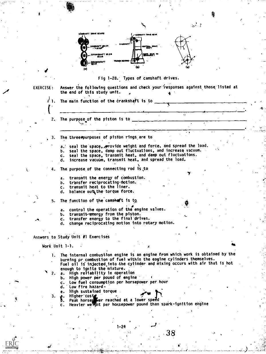
Fig 1-24. 01) control rings. r.The gap 'between the ends of the'cornpression rings Wien inserteecold in the
cylinder must be suffWently large so that, when the ring expands with the full pistontemperature, the ends will not be pressed together and buckle the ring. The way in which the.
ends are cut varies. Most rings have the'ends:cut square, figUre 1-25a. A design which makesgas blow-by more difficult has the ends cut at a 450 angle,, figure 1 -25b. There are, several
designs of step-seal rings, figures 1-2.5c and 1-25d. However, thete is littlehgained by this
more complicated shape. Oil control rings in two-stroke engines'are likely to catch the ringends in the ports over which the rings slide because of the ring flexibility. To prevent-this, sometimes the ends are notchetand a pin is installed in the piston groo0 to hold thering ends alAys in line with a bridge between theports.
frNO CT. AP ANC
to) AWARE CUT
7IA) ATTOLf COT
I e MAI ST(p CUT
1;c[
TA
r-INIECAP
1-I
A "PAW TOMAS TtosSiONA
IS) 0104040 STEP OUT JOAO TATTOCATtAL TENSION
Fig 1-25. PistOn rings.4
Connecting rods. The purpose of the connecting rod is to transfer the up and downmovement called reciprocating motion from the piston to.the crankshalt, where it istransformed into rotary motion. Connecting rods teed on military engines are mostly of the
type used An automobiles, figure 1-26a. They have an eye at the,sMall end for the piston pinbearing, a long shank, and a big-end opening which is split to take the crankpin precisionbearing shells/. The rods are forged of a high-strength alloy steel. Mosi connecting rods are
rifle-drilled from the big end to the eye for oil flow from the crankshaftto the piston pinand, in some engines, to the piston crown to cool 4t. Very often the rod shank is H-shaped
for maximum strength with minimum weight. Types of rods include:. (1) the normal shape (fig1-26a) used with only one cylinder to a crankpin of two cylinders,offset to the rods canoperate side-by-side; (2) fork-and-blade rods in V-type engines (fig 1-26b) in which the big-,end of on rod has the normal shape while the rod of the piston in the opposite bank is widenedand split into a. fork shape straddling the first rod; (3) articulated connecting rods (fig
1-26c) in which gne rod, the master rod, is of the conVentionat Oape except that it has aprojection off tfie shank with en eye to which the rod for the piton in, the opposite bank,
called the articulated or link,rod, is attached. Finally, there is the rod type used on the
pancake engine in which the big and of therod consists of a short pad with the bearing metaldirectly on the rod. Four such rods are located radially around the outside of the pads to
hold all four against the crankpin.,
1-22'
36
-1
I
I
-,,
..; The connects rod is connected !to the piston by a piston pin. The pin passes' through bearing suffices the piston and the connecting rod. The lower end of the
connecting rod is attached o the crankpin. As, the piston moves up and down in thikcylindere,the upper end moves up and wn but, because it is attached to the crankpin on.thetrankshaft,it must also move in a circl with the crankpin. Each movement of the piston from top to
.
bottom is called a stroke. The piston takes two strokes as the crankshaft makes one completerevolutiOn, an upstrOke and a downstroke. When the piston is at the top of a stroke, it issaid to be at top dead center (TDC). When the piston is at the bottom of a stroke, it is saidto be at bo)tOm dead center (BDC) These positions are called'rock positions._
Camshaft (fig 1-27). In some engines the camshaft is a straight round shaft and-the cams areTiTiFite pieces machined and keyed to the shaft. However, in most modern diesel`engines the cams and the shaft are forged or cast in one piece. The function, of the camshaftis to control the operation of the engine valves and, in some cases, the fuel injectors. Thisis usually accomplished through various intermediate parts such as push rods, cam followers,
$and rocker arms.
, I,
worm& ocipmemen moo'. PORK-ANOSIASEODIONCOMI APO
Fig :1 -26. Connecting rods;
MITIctx.mgocomae:40g NOD
catinilialtnEaDPig 1 =27. Camshaft a
, . ,.
.
The Camshaft is driven from the engine crankshaft by various means. Figure 1-28shows three different types of Camshaft drives. Figure 1-28a shows a drive by a train ofstraight spur or helic9. gears. Figure l-28b shows a drive by two pairs of helical or screwgears and an intermediate vertical shaft. Figure l -28c shows a chain drive; (m) is thecamshaft, (g) is the camshaft sprocket, (d) is the crankshaft, and (p) is the. crankshaftsprocket.
1-23 37
-
ti
CAIIIIKOT o IAR
1.
fel iv
Fig 1-28. Types of camshaft drives.
EXERCISE: Answer the following questions and check your responses against those listed at
the end of this study unit. , 4
di. The main function of the crankshaft is to
The purpose of the piston is to4
3. The threespurposes of pistbn rings, are to
a.' seal the space,,provide weight and force, and spread the load.
b. seal the space, damp out fluctuations, and increase vacuum.c. seal the space, transmit heat, and damp out fluctuations.
d. increase vacuum, transmit heat, and spread the load,
S
4. The purpose of the connecting rod is,to
a. transmit the energy of combustion.
b. transfer reciprocatingrhotion.c. transmit heat to the liner.d. balance ouiNthe torque force.
5. The function of the camshaft is to. 4
a. control the operation of the engine valves.b. transmit-energy from the piston.
c. transfer energy to the final'drives.d. change reciprocating motion into rotary motion.
Answers to Study Unit #1 Exercises
Work Unit 1-1. A
S.
a
1. The internal combustion engine is an engine from which work is obtained by the
burning pr combustion of fuel within the engine cylinders themselves.Fuel oil is injected.into.the cylinder and mixing occurs with air that is hot
enough to ignite the mixture.2. a. High reliability in operation
b. High power per pound of engine 1 .
c. Low fuel consumption per horsepower per hour
d. Low fire hazard. .
e. High sustained torque,;
. Peak horse
.
3. i. Higher coser reached at a lower spe d
c. Heavier we htt per horsepower pound than spirk-ignition engine
1-24
38
Work Unit 1-2.
1. b.
2. d.
3.' c.
4. a.
5. c.
6. d.
7. b. IP.
Work Unit 1-3.
1. C.
2. a. ;.
3. c.
4. b.
5. a. and c.6. b.
7. b.
Work Unit 1-4.
1. c,
2. b.
3. d.
4. c.5. a.
6. c.
Work Unit 1-5.
1. Work is defined as being the movement of a b9dy against an opposing force.2. the energy of movement of the tank is increased.3. the rate of work.4. c.5. b.
6. d.
7. b.
Work Unit 1-6.
1. c.2. Friction loss
Mechanical efficiencyThermal efficiency
Work Unit 1-7. 4
a
c.
2. The cylinder head seals the combustion chamber and,usuzilly contains the valves andpassages for intake and exhaust gases, the fuel injection nozzle, the air startingand relief valves, and passages for the cooling water.
Work Unit 1-8.-
1. transform the reciprocating motion of the pistons into rotary motion.4
2. transmit the energy of combustion through the connecting rods to-the crankshaft.3.
4. b.
5. a.
1,26. .
r;
- STUDY UNIT 2
PRINCIPLES, MECHANICS, AND PERFORMANCE OF THE DIESEL ENGINE
STUDY UNIT OBJECTIVE: KNOUT THE AID'OF REFERENCES, YOU WILL IDENTIFY THEOPERATING. CHARACTERISTICS AND PRINCIPLES OF THE DIESEL ENGINE. IN ADDITION, YOUWILL IDENTIFY SCAVENGING, PISTON AND CRANK TRAVEL, COMBUSTION AND IGNITION DELAY,IGNITION AND TIMING, AND THE CHARACTERISTICS OF SUPERCHARGING.
Work Unit 2-1. OPERATING PRINCIPLES IN THE DIESEL ENGINE
IDENTIFY THE DIFFERENCE BETWEEN THE TWO AND FOUR STROKE CYCLE ENGINE.
EXPLAIN THE COMPRESSION RATIO OF A DIESEL ENGINE.
IDENTIFY TWO METHODS OF BURNING FUEL WITHIN THE CYLINDER.
A series of events which reoccur regularly and in the same sequence is known at acycle. The cyclic sequence-of events in a diesel engine is (1) filling of the engine cylinderWith fresh air (intake); (2) compression of the air charge in order to raise its pressure andtemperature needed to'ignite and burn the fuel efficiently; (3) combustion of the fuel andexpansion 'of the hot gates; and (4) emptying the cylinder of the burned gases by exhausting,them. When these four events are completed, the cycle is repeated.
Four-stroke cycle. When these-four *pots take place during four strokes'cif the , .
piston, the cycle is cilTed a four-stroke 'cycle. The positipAtof the piston when -it isnearest to the cylinder head farthest 4wWform it are called top and bottom dead, centerrespectively,pdicated as TDC and BCC. The, reason for this designation is that at thesepositions the connectingarod.tenter-line coincides with the crank-throw center-line and thepiston cannot be moved by gas pressure .acting Upon its surface. The force to keep the pistongoing up. And dawn must come from the.rotating crank acting through the connecting rod. Thefour main events in a four-stroke cycle are shown in figure 2-1.
MASS UMW,VALVE wiLWL wag 014041111
vfrog vmma
cosoiwskon
gutctiow
Fig 2-1. ,Four-stroke-cycle diesel engine.
During the first intake stroke (figrod, the lower end of which is moved by,thecylinder as it moves doward. Outside airvalve which opens at about the- beginning, ofreaches bottom dead center'(HDC).
[waist
(a)
2 -la), the piston move's downward by the connectingcrank. The piston motion creates a vacuum in theirdrawn into the cylinder through the intakethe intake stroke and stays open until the piston
Whip the'piston has-patsed ODC,.the second or Compreision stroke begins (fig 2 -lb).The intake valve closes and the upward motion of the piston pushed-by the crank and theconnecting rod begins to compress the air charge in the cylinder.
Shortly before the piston reaches top dead center (TOC), liquid fuel in a finely atomizedspray is admitted intg_the cylinder containing hot compressed air The fuel is ignited by theheat pf "the air compressed in the cylinder and burns. during the first part pf the downwardpiston stroke. During this downward or third stroke called'working4r power stroke: (fig2-1c), the hot gases, whose pressure was considerably increased by the combustion of the fuelcharge, force the Osten downward and expand due to the increasing cylinder volume.
042.41.v.1'. .4. ,
fi
1
0'
Shortly before the piston reaches the bottom dead center, the exhaust valve opens (fig2,1d), and the hot products of the combustion, haviAg a'relatively high pressure in. spite ofthe previous expansion, begin to rush out through)the exhaust ports into the outside -
atmosphere. During the following fourth ocebeust stroke, the piston moves upward, pushed bythe crank and connecting rod, expelling the remaining products of conbustion. Near top centerthe exhaust valve is closed, the intake valve is opened, and the whole cycle starts again. As
'can be seen, the four strokes .require two .engine revolutions. Thus, in a four-stroke-cycleengine, one per stroke obtained for every two engine revolutions., Actually, the div,idingpoints between tie four main events do not come at the Very beginning lid of the
,.corresponding strokes. The differences are smaller in low-speed engine increased as theengine speed increases. The intake valve is opened 10 to 25 crank-angle green before topdead-center and is closed from 25 to 45 crank-angle degrees after, bottom- c Ater. The fuelinjection starts some 7 to 26 degrees before TDC. In order to release th exhaust° gases inproper time, the exhaust Valve begins to open 30 to 60 degrees before BDC and close 10 to 20degrees after IOC.
4 ..
Two-stroke-cycle events. A two-stroke is compl'ted in two strokes or one revolutionof the cranksiliff, whereas a four-stroke cycle is completed in four strokes or two revolutionsof the crankshaft. In other words as two-stroke-cycle engine completes the four eventscycle in two strokes of the pistpn. .0n Stroke is down and one is up. Each up,and downinovemept of the piston will turr the crankshaft once. So a two-stroke-cycle provides power tothe crankshaft on each revolution or turn. Compare this to the four-stroke cycle engine wilichwill have two up and two .down movements but only one of those movements will be a powerstroke. The main mechanical difference between the two -stoke and four-stroke engine is the "\method of removing the burned gases' and filling the cylinder with a fresh charge of air. In afour-stroke engine these operations are performed by the engine piston during the exhaust andsuction strokes. In a two-stroke engine these operations are performed near the bottom deadcenter by means of a seperate aid' pump or blower.
,rThe compression, combustion, and 'expansion events do not differ frgin those of a
four-stroke engine. The filling of the 'cyl inder, called scavenging, with a fresh 'charge maybe explained as follows: v.fieh the pistbn has travelled 80 to 85 percent of its expansionstroke, ebaust valves e, e (fig 2-2a), are opened, the exhaust gases are rsleased apd be.ginto escape from the cylinder. The piston continues to move toward the botto' center bnd soon
.uncovers ports s, ,s, thrqugh which slightly compressed air begins to enter the' cylinder. Thisair, having a slightly higher pressure than the hot, gases in the cyl inder, pumps -rout the hotgases through valves e, e (fig 2-2b)., 'This-operation is called scavenging.. The air admitted -is called scavenge tiir and the air mini Unice ports, Icavenge ports. About the time when thepiston on its upward stroke close ports s, s, the exhaust valves e, e are also closed (fig2-2c), and the ion stroke begins. J.
se
(0) (b) (0)
Fig 2-2. Scavenging of a two-stroke engine.,
41.2-2 .
. The advantage of-a two-stroke operation is the elimination of one scavenging and onecharging stroke required, in four-stroke ,Ocle operation. Thus, the cylinder delivers onepower stroke for every revolution of the engine as compared with one power stoke for every tworevolutions in 6 four-stroke-cycle engine. It might appear that a two-stroke-cycle engine'Could produceotwice as much horsepower as a four7srfoke-cycle engine of the same sizeoperating at the same speed. However, this is not the case. In order to scavenge the burnedgases at the end of the power stroke and during the time both the intake and exhaust ports areopen, the fresh air rushes into and through the cylinder: A portion of the fresh air mingles .
with the burned gases and is.carried out the exhaust port. Also, due to a much sfiorter periodthe intake port is open (as compared to the period intake valve in a four-stroke-tycle engineis wen), a relatively smaller amount Or air is admitted. Hence, with less air, less powerper power stroke is produced as compared to the power prodyced in a four-stroke-cycle engineof like size operating at the same speed-and with gther conditions being the same. Toincrease the amount of air entering the cylinder, arxiliary devices are used withtwo-stroke-cycle engines.
o 8
These advantages are very important" an hence two-stroke engines are used in theMarine Corps-much more often than four-stro engines. A disadvantage of twe7stroke operationis higher working temperatures df the pist and cylinder head due to combustionlccurringevery revolution and resulting in distor on of these and related parts.
-46
Compression. There are two reasQ or compressing the air charge duringlithe second.r compression stroke. The first is to ra e the thermal or overall efficiency df the engine ,
by increasing the final tfterature of combrtstion. This ?tulles to all internal-combustionengines both of the spark-ignition type as well as the mo-called diesel type. The secondto increase the temperature of the air charge so that, 'Oren the finely7at'omized fuel .is 'injected into the hot compressed air, the fuel will ignite and begin to barn without anyoutside fourcsrof ignition such as the spark plug used in automobile engines.
. . ,..,.
TheicompressiOn ratio of an engine (fig 2-f 3) is the volume in one cylinder with'the
piston at bottom dead centlIr (displacement volucse plus clearance volume) divided by the volumewith the piston at top dead center (clearance volume). This ffgure indicatei the actual.amount thatthNior drawn into the cylinder will be dompressed. For example, suppose that an
S" 'engine cylinder s an air volume of 60 cubic in oss4ith piston at bottom dead center and a'
volume of 10 cubic inches with the piston at t deadcenter. This gives a compressiOn ratio
j,.
of 60 divides by 10 or 6:1. That is, the air is compresfed from 60 to 10 C011ic inches, or to1/6 of its orginal volume, on the. compression stroke. CampressiOn ratio is designated by r.Compression patio = volume at bottom dead center (V1) volume at top center (V2) or
4
Al
p
r = Vi V2.
MON AT MC
MON Al
411AFig 2-3. Compression ratio is ratio betweln "Vimrand "V2 ".
The volume V2 is called the compression or combustion space. The0 -volume VI is equal tothe sum of the piston displacergnt of one cylinder plus the combustion spaces.
4
f:
414
2-32 P
5'
:**
Diesel engines use compression ratios of 12:1 up to about 22:1. Theoretically, thehigher the compression ration, PlOighet the thermal efficiency of the engine an the. lower
its fuel consumption. As the compression ratio is-increased, the air drawn into the cylinderis compressed into a smaller space. This means a higher -initial pressure at the start of thepower stroke. It also means that the burning gases-can expand a greater amount. Thus, thereare higher pressures for a longer period on. the power stroke. More power is obtained withedch power stroke: Therefore,.increasing compression ratio increases the power output of an
engine. Racing-car-builders shave cylinder heads so as top reduce theyolume of the combustionchambers and thereby increase ratios. By this one act, the power output of an engine can beincreased several horsepower. However, an increase of the compression ratio is accompanied byhigher gas pressures and combustion temperatures. ThAs causes stresses and pressures invarious engine parts.-.To counteract these ill effects, stronger heavier-parts are requiredwhich excessively increase the weight of an engirie. Higher temperatures and pressures alsoincrease the wear and tear-of an engine and thus fecrease it reliability. One way to avoidproblems brought about by increasing Compression ratios is to find 'a fuel that will not causedifficulty from combustion. .
Combustion. 'There Are two distinctly different_ methods of burning the fuel in anengine cylinder: (a) at arcohstant volume and.(b) at a.constant-pressure. Combustion at
constant volume means that during combustion the volume does not change and that all .the heatenergy developed by the fuel goes into an increase of the gis temperature and pressulq. In
the case of an engine combustion at constant volume means that !combustion proceeds at suchhighate that the piston has practically no time to move during.combustion. Such acombustion is obtained when the piston is petsing top center. The advantage of this method offuelrcembuttion is a high thermal efficient'. Its disadvantage is a very sudden pressureincrease and resulting noisiness of therengine. Such combustion comes close to that of a
spark-ignition gasoline engine.
Combustion at constant pressure means that during combustion the temperature 'increasesat such a rate that. the resulting increase of pressure .is just enough to,counteract-the.influence of the increasing volume, and the pressure does not.change. The heat energydeveloped by the fuel goes partly into an increase of the gas temperature and partly intoperforming.outside work. In the case of an engine with constant, pressure combustion, the fuelis burned so that the pressure atthined at the end of the compression' stroke is maintainedduring the greater part of the Combustion eve t. Such a combustion was:used in the originalOlow-speed, air-injection diesel engine. Itdvantage is a smoo6ly running engine producinga more even tome due to the extended combustion pressure., However, it is not suitable for
high -speed diesel engines.
High-speed diesel engines of the present operate -on a cycle which is approximately a
combination of the above two methods. Part of the fuel is burned rapidly almost at a constant
volume near the top dead. center. The rest is burned while the piston begins to move away from
the top center. However, the pressure does not remain constant, but usually'increases and
then decreases. In lenpral, this cycle more nearly'resembles the constant-volume combustioncycle than the cycle of the original diesel engines. Its advantage is high efficiency with
low-fuel Consumption. Its-drawback is in the difficulty of preventing rough and noisy
operation of'the engine.,
%
EXERCISE: Answer the followingAquestions and check your responses against those listed atthe end of thiss stOdy unit.
..
1. .A'two-stroke cycle is"compfatet in revolutions of the crankshaft.
-a. Apne 11 c. three1b. 'Iwo " ' d. four
2". .ANOUr-stroke,cycle is completed in revolutions of the crankshaft.. .
a. one c. thr
b. two4 '
d. four
3. TheMlling of the Cylinder with a fresh'air ciiarge is dal led
.,.
a. pressure. c.- replenishment.
b. -scavenging. d. intake stroke.
AP'
4. A series of events that reoccur regularly and in the same sequence is kiltown as a
a. stroke. .c. cycle.
b. crank. d. poWer stroke.
2.4
.
)
The four events that take place in the operation of the diesel engine are th6intake of fresh' air, combustion of the fuel, and
compression and release.b. exhaust and compression.c. exhaust and detonation.d.. detonation and compression..
46. Shortly before the piston reaches'bottom dead center in a four-stroke4tycle
engine, on the third stroke the
a. fuel -is injected into the cylinder.b. exhaust valve closes.D. exhaust value opens.c. outside air is being drawn into the cylinder.
7. The major advantage of the two-stroke cycle engine is that
a. it reaches maximum speed quicker.b, it eliminates the extra up and down stroke.c. the pressure in the cylinder is less.d. it shuts down much more quickly.'
8. Explain the compression ratio of a diesel engine.
9. Explain why either a high or low compression .ratio is better for uses in a dieselengine.
10. The two methods of burning the fuel in the engine cylinderare or
.
lf. .From the illustration below identify each of the foOr-stroke cycles shown.' Placeyour Answer in the spaces provided.
a.
0
If
k 6. c.
6
2-5,44
owesVOLK
d.
S.
C,!
Work Unit 2-2. THE DIFFERENT METHODS OF SCAVENGING
GIVEN A SPECIFIC SITUATION, IDENTIFY CROSS-FLOW SCAVENGING.
GIV5! A spiliim SITUATION, IDENTIFY RETURN-FLOW SCAVENGING.
GIVEN A SPECIFIC SITUATION, IDENTIFY UNIFLOW SCAVENGING.p
17-,7-
4
IVEN AieEyfIG, SITUATION; IDENTIFY TWO METHODS OF PROVIDING AIR PRESSURE' TO THE
General. Figure 2-2 illustrates one of several methods of cylinder scavenging. In
sane engines Ehe exhaust gases areNet out through ports, uncovered by the pigton the safe as
the scavenge ports. There are three basically different methods of scavenging: direct or
crossflow scavenging (fig 2-4), loop or return-flow scavenging (fig 246), and uniflow
scavenging (fig 2-2).
j op4r.
Fig 2-4. Direct cross-flow scavenging Fig 2-5. Return or loop scavenging.
a. Direct or cross-flow. In direct or cross-flow scavenging (fig 2-4) the piston
uncovers 'first the exhaust ports, e,,, and releases the pressure; going .down farther, the piston
uncovers the scievengeports, b, and begins to admit slightly Compressed .air whose stream is
directed mainly upward as indicated by the arrows, and thus pushes out the exhaust gases
through ports e. Having passed the dead center, the piston first closes the scavenge ports
and soon afterward the exhaust ports. The faot that the exhaust ports are closed after the
scavenge ports, permits some of the air charge to escape from the cylinder. This is a
disadvantage of the scavenge method. However, it has the definite advantage of simplicity of
construction and maintenance due.to aksence of valves which must be kept tight.
b. Loop or return-flow. Loop or return-flow scavenging (fig 2-S) "is similiar to
cross-flow scavenging in the sequence of the port opening. The direction oratr flow is
different as indicated by the arrows. Its advantage is that the bulky scavenge-air and
exhaust-gas receiver are located on one side of the cyl !icier, thus giving better
accessibility. This method is particularly suitable fo -double-ecting engines,. because the
operation of the exhaust valves (fig 2-5) for the lower combustion space becomes Very
complicated. When used for double-action engines (f 24), the scheme is'AmprOVed by the .
introduction of rotary exhaust valves, r. During e release of the exhaust gases, valve r is
open but is being closed when the piston on the re urn, stroke covers the scavenge ports. This
arrangement eliminates the escape of air charge din* ng the beginning of the compression stroke
when the exhaust ports a o not yet covered. Some t after the bxhaust ports are covered by
the piston, the rotary lye is opened, getting'it ready for the next cyale. As shown in
figure 2-6, the length of the piston is exactly equal to the length of the stroke. This
done in order to control the exhaust and scavenge events alternately by the upper and lower
edges of the piston.
45
4
r"4
#
-Fig 2 -6. Return scavenging in a double-acting engine.
.
c. Uniflow scavenging. The opposed-piston method is shown in figure 2.7. The lowerpiston controls the exhaust ports, the upper one the scavenge ports. To obtain the necessarypreliminary release of the exhaust gases or an uncovering of the exhaust ports ahead of thescavenge pelts, the crank of the lower crankshaft is advanced in respect to the crank of theupper crankshaft. The lower crankshaft leads the upper crank'by some 10 to 15 degrees. Inthis way the exhaust ports are opened first (fig 2-7a). When the pressure is sufficientlylowered, the scavenge ports are uncovereci(fig 2-7b), and scavenging begins to take place.After the exhaust ports are closed, more air is admitted -(fig 2-7c) until the scavenge portsare also covered and compression of the air charge takes place (fig 2-7d). Just before the .
pistons reach the point at whichthey are closest-together, fuel is injected, igmited, andburns while the expansion stroke starts (fig 2-7e). The power delivered by the upper pistonsto the upper crankshaft is transmitted to the lower main crankshaft by means of anintermediate vertical shaft and two pairs of bevel gears. The advantages of this method are:
(1) Very efficient scavenging of the cylinder and h;nce greate'r power is developed.
OP
(2) Abtence of valves and valve-operating gears.,
(3) Absence of cylinder heads which are complicated castings and a source of troublein engine operation.
a-(4) Gbod accessibility for the inspection and repair of parts, with 014 exception of
the lower crankshaft.
The two scavenge methods shown in figures 2-3 and 2-7 are classified as unif lowscavenging. In both cases, the exhaust gases and scavenging air are flowing' in the samedirection with less chance for formation of turbulences wish are unavoidable. with cross- andreturn -flow scavenging. -
ti
1
NI I,) la)
Fig 2-7. Opposed-piston engine operation.I
There are ically two methods of providing ate pressure to the cylinder. These are
by the compression# air in the crankcase and by using:a pump.
Compression of air in the crankcase takes place through tr-check valve. The descending
piston creates a-back pressure on its expansion stroke. This.movement causes the check valve
to close. This method produces little air pressure and is generally'used only on The
two- strookq cycle engine. ;
Thecategory ofstudy unit.
EXERCISE:
umps that ire used come in may varieties but they all fall into a general
ing either blowers or superchargers. These will be covered later within this
Answer the. following questiods and check your responses against those listed at
the end of this study unit.
Identification (items 1-3): Identify the three methods of scavenging as given in the,
situations provided below.
The piston uncovers first the exhaust ports, and releases the pressure, going
down farther, the piston uncovers the scavenge, ports and begins to admit slightly
compressed air, whim stream is directed mainly upward, an thus pushes out the
14haust gases.
a. Return-Pow scavengingb. Uniflpw scavengingc. Cross-flow scavenging
2. The sequence of the port openings is theair flow is different. .The air port andSide of the cylinder,, thus giving better
a. Return-flow scavengingb. Uni-flow scavengingc. Cross-floW scavenging
2 -e
same as in the first it nation, but the
exhaust gas port are Ibqatedlan the Metaccessibility.
47
otj
t;
3. The lower pistons control the exhaust ports and the upper one the scavenge ports.In order to obtain the proper sequence for intake and exhaust, the lowercrankshaft will precede the upper crankshaft by 10-15 degrees,
a. Return-flow scavengingb. Uni-flow scavengingc. Cross-flowiscavenging
. The two methods of providing air pressure to the cylinder are by the use of a
a. pomp and a blower.b. blower and 0 WperCharger.c. pump and compression of air in the crankcase.d. supercharger and compressiOn of air in the cylinder.
Work Unit 2-3. 1HE DIFFERENCES IN A COFFARISOeBETWEEN THE GASOLINE AND DIESEL ENGINES
STATE MECHANICAL SIMARITIES BETWEEN GASOLINE AND. DIESEL ENGINES.
STATE THE MAIN DIFFERENCES IN PRINCIPLES OF OPERATION BETWEEN GASOLINE AND DIESELENGINES.
General mechanical construction." The diesel engine is mechanically similar to thegasoline engine but is heavier intonstructIOn. Both engine types.use,air, fuel, compression,and ignition. Intake, 'compression, power, and- °whet& occur in the same sequence.Arrangements or pistons, connecting Todsvand crankshafts are similiar. Both are internalcombustion'engines; that is, they-extract energy from a, fuel-air mixture by burning themixture inside the engines.
Fuel intake and ignition of fuel-air mixture. In principles of 'operation, the 46differences between gasoline and diesel engines (fig 2-8) are the two different methods ofintroducing the fuel into,the cylinder and of igniting the fuel-air,mixture. Fuel 'and air aremixed together before they enter the cylinder of a ga oline-engine. The mixture is compressed
imeby the upstroke of the piston and is ignited. within t e cylinder by a spark plug. -(Devicesother than spark plugs, such as "firing tubes," are s times-used). Air alone enters thecylinder of a diesel engine. The air is compressed eg.the upstroke of-the piston and the.diesel fuel is injected into the combustion chamber near the top of the upstroke (compression,stroke). The air becomes greatly'heated during/compression and the diesel fuel ignites andburns as.it is injected into the heated air. No spark plug is used in the difiel engine;ignition is by contact of the fuel with the heated air, although "glow plugs" are used in somemodels of diesel engines to assist in st tng. Pressure developed by the compression strokeis much greater in the diesel engine. F r ch pound of pressure exerted on the air therewill be a temperature increase of about 200F. At the top of the compression stroke when
.... pressure is'highest), the temperature in 0 chamber will be about 1,0000F. this heatignites the fuel almost as sop as It is in ected into the cylinder. The pi/stop, actuated bythe expansion of burning gases, t moves down on the power stroke. In a gasoline engine;the heat from.compression is no enough to ignite the fuel-air mixture and-a spark.plug is.necessary.
1
/
w.
/4.
10,
p
110
I
sr?
I
0430184
ON 111040ePA110 110041 d Post0e4 PPIAIT44141 Offtf, *HP AlT404MIIIC PlITPOPIMIKIS A! 060404 CA140,1101 wwPfl II11OE4 I. A /44t11414 C04144,41.1411 CsA401 Of0444 nil WIMP 0011 nU rmt v04451vaa44 orto C444.4c14 MALI 4,4(41.0 IT tr44
ON 14011,041 Of 0441044. vATVIIS All (10440-ANO w41l$11 If C06114(3140.U1UMIV 1104 POTO 17311& 031111011011 COP1441110N WooOP 4140.1Pal
0004f11$440 AulITURO II KYOTO ITSUPCTIPC YAM 444! Op COPIUTOON CAU114POTKIfUi IIPANSION 01 climb.. 0A111AOAiNIP POTOPP. Munro° 0110%11 }MON.
ON 0044TANA*0 MOO 0$ 0441014. 00AXIVAIVI 011141 A140 AIA4011401 IC SSSSSOOKTT PIM AN 0410 MI (I11044 AG VACAII0 N OM 'TOON. TWIN BONO NO CAN A),11101 01 ONOTTIP VMVI CTO14444 1414 WOWSAW .J;PJAPTOTT Of As. 4T0APOIT14 01 WAD04 oil 04441
ON VS14041 Of 11084, vALVIS AM CIOSIO.AND All if cOmPelOil) TO APIOAPAMPUT TOO
10014 COmpoISSION 040041C11 MOM TVAPI4A-004 SPOMANTous *boom op foe 44.
moo) MO OW CI comreeSsiON Slime14141 01 CO1LAUSII0A4 INPAHOS CTON014 0811$ADAIP431POI0fd. NUTTING 04 0448 MOO
Fig 2-8. Comparison of sequence of events in diesel and gasoline engines:.11
Control of speed and power. . The speed and the over output of diesel e ines'ore
controlled by the quantity of fuel injected into the inder. This is opposed o the cocoon
gasoline engine which controls speed and power output b4limiting the amount of air, admitted
to the carburetor. The difference is that the diesel engine controls the qu ity Of
wherea the gasoline engine regulates the,quantity of air:'-. In the diesel engine, a varying
amount of fuel is mixed with a constant amount of compressed air inside the. tylinder. A fuil
charge. of air enters the cylinder on each intake stroke. Because the qughtity of air is
constant, the amount of-fuel injected determines power output and speed. AO. long as the
amount of fuel injected is below the maximum established by the Manufacturer in 'designing the
engine, there is always enough air in the cylinder for complete combustion. A device in the
carburetor of the gasoline engine controls the amount of air admitted. The amount of air and
its velocity, in turn,sontrol the quantity of fuel that is piked up and mixed air to be
admitted to the.cylinder. 'The amount of mixture available for combustion determines power
output and speed. It is apparent, therefore, that the controlling factor is the quantity and
velocity of air passing through the carburetor. .
),Combustion rocess. In the diesel engine, there" is continuous combustion-during the entire
ng the power stroke. Pressure resulting from combustion remains' approximately constant
hroughout the stroke. In the gasoline e ine, however, 'combustion is completed while the
46 ,piston is at the upper part of its_trav
li about the same-during most orthecombuvolume increasec there Is little additionalthese facts, theNcycle of .the gas line engine
fcombustion while the diesel cycl is said, to ha
eN.
.1
This means that the volume of the migture:stayi
prodess, When the piston does move down and theombustio% to maintain pressure.- Because of
often referred to as having constant-volumeconstant-pressUre combustion.
?-10.49 \\
EXERCISE: AnSwer'the folldwing questions and check your responses against those listed at heend of this study unit.
1. The design; of the gisoline diesel engines are similar, butthe R
1 is heavier in' weight.
2. Both engine types use air, fuel, ignition, and
3. In both engines, intake, compression, powerf and exhaust occurin
4, There are similarities in the arrangement of pistons;connecting rods,and
5. The control and speed of thequantity of fuel Injected into the cylinder.
engine is controlled by the
6. The control and speed ofi the engine is controlled by the amountof air proviied to the carburetor.
7. Combustion is completed while the piston is at its uppermost point of travel inthe engine,
8. Combustion continues for the length of the power stroke in the%pine.
Work Unit 2-4. THE MECHANICS OF PISTON AND CRANK TR104.--(?:
EXPLAIN THE MOVEMENT OF THE PISTON.
IDENTIFY INTERTIA.-
IDENTIFY ONE FUNCTION DF. THE FLYWHEEL.
The movements of the, piston are transmitted to the crankshaft by means of a connectingrod. These three members (rEston,Jonnecting rod, and crankshaft) transformed the up and downmotion of the piston, called reciprocating motion, into rotary motion. For all practicalpurposes, the travel of the crankpin can be considered to be a uniform motion along a circledescribed with the radius equal to the length of the crank throw.
A
While the crankpin travelis uniform and has a constant velocity, the piston, travel isnot uniform and the piston speed constantly varies. At each'dead center, the pistowcomes toa standstill; its speed becomes zero. As the piston begins to move, the speed graduallyincreases and reaches a maximum ;then the angle (a) (fig 7-9) formed by the crank and the,cylinder centerline is equal to 900. After the position, the piston speed-begins todecrease and at thdead center again becomes zero. '
b
CRANKSHAFT
CENIERXIWE
I 'uI
V SPEED "0"
CYLINDERCENTEFUNE
MAXIMUM SPEED
Fig 2-9. Piston speed.
2-11 5
CRANKSHAFTCENTERLINE
f .1
e.
Inertia is the resistance of a body to change Of motion. It is the tendency ofobject 'to remain stationary, or to continue to move if it is moving. Inertial as such cannotbe measured directly; however, it can be.expressed in-terms of the force which must be appliedto a body in order to ,change its velocity. As with any force, inertial forces are expressedIn pounds. Since the change of velocity is called acceleration, inertia may be defined asbeing equal to that force which must be applied to 'a-body in order to imOrt to it a certainacceleration, either to speed it up or to slow it down as the-case may be. The force of
inertia of a body depends upon the rate ortange of Its velocity. The shorter the timeduring which a change takes place, the higher the required acceleration and the greater theforce of inertia becomes.
A flywheel stores up energy during the working stroke and gives it back during therest of the cycle, It serves four main purposes:. (1) to keep the variations In speed within
desired limits at all loads;. (2) to limit the instantaneous rise or fall in speed duringsudden changes of load; (3) to carry the pistons over the compression pretsure when running at11 or idling speed; (4) to help bring the engine up to speed when starting.
In multicylinder engines, the torque a( the end of the crankshaft becomes moreuniform, and the required weight of the flywheel becomes very small. The cranks, crankpins,
and large ends.of the connecting rods have considerable weight and exert the same influence asa flywheel. Therefore, in some large, multitylinder, marine dietel engines, flywheels are notnecessary and hen are not used.
EXERCISE: Answer. e following questions and check your responses against those.listed at-,the end of4his study unit.
the movement of the piston.1. E 1
2. The re s,i stance of a body to.l'thange
a. st tionary.b. In ia. 41
in motion is.,called
c. tendency, .
d. accelerittion:.,
`-3. Which of the'following'is a functiOn of ihe flywheel?
a. To store energy throughout the cycles like a battery
. To illuminate the limits of torque riseTo regulate the combustion of the fuel- '01-.
d. To help bring the engine up to speed when starting
Work Unit 2-5. COMBUSTION AND IGNITION DEL
IDENTIFY( pNUION DELAY.
'DESCRIBE COMBUSTION IA THE DIESEL ENGINE.1
Regardless of how finely atomized the fuel injected into the combustion spae of the
cylinder filled with hot air is, it takes some time before the relatively cold fuel spray
becomes heated and vaporized,enough to ignite and start burning. This time element is rather
small when 'expressed as a fraction of a secondi, but quite noticeable when referred to as the .
number of degrees the crank travels between thb moment when' the fuel is introduced int. the
,cylinder and when the first particles of it are nited. Thit time element is called ignitipn
delay or ignition lag and amounts to several deg es of crank.travel.
After ignition has started, the fuel, wh by this time has already been introduced
in the cylinder, w 11 burn.. This combustionutua ly is accompanied. 40 al'rather quick pressure
rise. In 'the mean tine, the pump continues to d_liver fuel, and during the third period of
combustion, the fue burns more or less as it is introduced. However, sive the supply of
oxygen in the air c arge gradUally is being used up by the combustion, thd fuel particles.
introduced toward t end of the injection have more difficulty meeting Ilhp necessary
particles of oxYge . Combustion is consequently retarded and, when injec on is terminated,
some unburned fuel is still present in the cylinder and continues burn. The piston by this
time has moved awe form the dead center and its speed increases; therefore: the pressurebegins to fall in ite of additional heat being developed by the rest of the fuel.
C
lip whole procedure can be illustrated by the presture-crank angle diagram (fig2-10). Point A is the start of the injection, lent B is where ignition occurs, and periodA-B is ignitiqn delay. Up to point E the presare rises very fast. Period B-C corresponds toburning of th; fuel introduced up to this point and represents the first or uncontrolled-combustion. From C to D the fuel'burns more or less as it is introduced, giving the second orcontrolled combustion.'t From point D the fuel burns with" he pres ure dropping - this is
1after-burning. After-butning may continue through a co erable distance Of the expansle-stroke. ,
i
giok01.10Nmissunt Macbat .
InOLORRNrtOytenoAr C.cI
- - Cot \41..t.0
11I i§ I A;;Ttot 'eNt1:7.: IH "tt,* 4.4.11
.
OCORCIM GR./4 AmOtt OR TtSCOONOSI
Re
Fig 2-10. Pressure-time diagram of combustion process.
The highest thermal efficiency is 'obtained from the fuel which burns at the highestcompress* ratio at top centers In practice, burning of the fuel must start before Op dead\center and be completed after top dead center. The shorter the peridd of combustion, thehigher the thermal efficiency, and the lower the fuel consumption. However, an excessivelyshort burning period requires a fast presiure rise and produces:high maximum pressures. This
is undesirable as far as the quietness of engine operation, pressures, and stresses in variousengine parts are concerned.
. . ,
In order to obtain efficient, smokeless combustion, the fuel injected into themustcylinder must be broken up into very fine particles and must be well atodizedt and the fuel
particle must be distributed uniformly through the whole combustion space. In air - injection
engines, e distributMon of the fuel is accomplished through a thorough mixing of theInjection air carrying the atomized fuel withthe air in the cylinder. In mechanical or
solid-injection engines, distribution is accomplishedby using nozzle tips with several holesand ly directing the fuel sprays so as to reach the desired portions of the combustion spaceor by using pintle-type nozzles with a cone - shaped spray. In larger engines, fuel isdistributed better by using-tio or more separate fuel nozzlet, each having several holes orfan-shaped sprays.- However, fuel distributed by separate sprays Is not sufficient. Fuel
distribution in the air charge is improved by stirring up the air in the combustion space andby creating air turbulences, thus mixing ai having too much fuel with airmhich does not haveany fuel.
While theoretically l' lb of air is sufficient to burn completely 0.065 lb of fuel oil,actually not all of the oxygen of. the air will be repthed by the fuel particles. Hence, onlya smaller amount of fuel, on the average not over 0.052 or even 0.04, lb, can be burnedefficiently with 1 lb of air in the combustion chamber.
..
Turbullters in the air-charge help to reduce the amount of air not reached by the fuelparticles-and thus help to increase the ;power output of the engine. Turbulences may becreated by.various means, including special shaped of the piston crown or of the entirecombustion chamber. Figure 2-11 shows-examples of different turbulent heads. In figure 2-11a.a turbulences are treated by restriction through' which the air has to pass when the piston'moves upward. The air velocity at the restriction is several times higher than before andafter it, and the change of velocity creates a turbulent flow into which the fuel As injected
10 form the fuel nozzle. Figure 2 -lib shows a Recardo-Convent head used in Waukesha dieselengines; here turbulences are created net only by the'restriction, but alsohy; forcing the airto travel oh a circular path.' Figure 2.-11c shows a turbulent head used. in Hercules dieselengines which is- similatto the Ricardo-head, However, it has an additiobalJeature. Whenthe piston approaches 06 ,dead center, it begins to cover partially the air passage betweenthe cylinder and turbulence chamber. This increases the air velocity.in the passage, andmakes a more 'turbulent flow of air into which the fuel is injected from the nozzle, f.
-.
2-13' 52
01)
Fig 2-11. Turbulent heads.
Turbulence in a two-stroke mines is created by making the scavenge-air ports-
tangential or angled as shown In figdte 2-12. Note that a citcular movement of the aircreated during scavenging continues up to 09 time of fuel injection, in spite.of the factthat the air has been displaced from one end of the cylinder to'the other and compressed to asmall. fraction of its original volope.
Fig -12. Turbulence in a' two-stroke 'engine.
Another method of creating turbulence is used in the so-called Lanova energy cell (fig2-13). The fuel is injected from the nozzle; a part of the fuel is atomized as it leaves thenozzle, ignites, and burns in the main combustion chamber. The rest is injected in a more orless solid stream into the so-called energy cell or minor air cell. Here it is atomized or-broken up idra fine mist form and ignited. The resulting combustion raises the pressure inthe minor air cell over the pressure in the main combustion chamber and, throws the burned andunburned fuel back into the main chamber. This creates a strong turbulence (indicated by thecurved arrows) and helps to burn the rest If the unburned fuel.
yffideri,
401.94"
I 1.111110111
WI SILL
1111W«SWAMI
Fig 2713. lanova combustion chamber with energy, cell -.
2-14 f 53
EXERCISE: Answer the following questions and check your responses against those listed atthe end of this study unit.
1. The tins it takes before the cold Nel spray is' heated to the combustion point isknoci as
a. time lag.b. igiition delay. d. retarded i gni tion.
TUrbul ence in the air charge will
c. retarded combustion.
3.. Turbulence in the No-stroke engine is created by
4. The combustion chanter that uses the energy cell principle is the
5. The highest thermal efficiency is obtained from
Work Unit 2P-6. IGNITION AND TIMING
IDENTIFY CORRECT FUEL TIMING.r
As already explained, there exists arcertain time lag between the time that the fielis ilijected into the cylinder and the time that it ignites and begins to burn and raise thecyliOr pressure. This time lag, called ignition delay, requires an advance of the fuelinjection several crank-angle degrees efore top dead center. In additiOrt,it should be notedthat there is another lag in the fuel injection. The beginning of the delivery s 9ke of theinjection pump is set to correspond to a certain position of the engine crankshaf Thefnjettion timing is checked by slowly turning the engine over.- The actual adnission, f thefuel into the cylinder will 'start several crank-angle degrees later.. The reason for dill timelag is the mechanical flexibility of the injection mechanis'm, taking up of clearances betweenthe various rollers, pins, and levers, and the compressibility of the fuel oil, especiallynoticeable with a long fuel line. This lag is called injection lag and amounts alro toseveral crank -angle degrees. , t. .
,.,. .
Both the ignieron lag and injection lag depend upon a number of various factors.-andmay. vary considerably from engine to engine. The following data obtained from an actual testmay serve as an illustration. In an engine operating at 900 rpm, the injection was set to re
begin at 22u before' to center IBTC1; actual injection started about -l7 u OTC which givesan -injection lag of 5u;. ignition started 8u BTC which gives an igniton delay of. 9u or atotal lag of 14u behind the nominal fuel timing. On the other hand, the pump deliv-ery s*,stroke was cut off at 30 B?'C, but due to the expansion of the fuel compressed in the `1 el
,...line thebactual end of.injection occurred slightly after IC.-- In other engines the, lag be 4,--
greater or smaller. . , ' 4:-.-:".. ,.
. The only way to determinetthe correct Nel timing is by operatingithe engine, changingthe timing, and finding the timing at Which the engine operates best, i.e., has the lowest,fuel consumption, carries the highest loasliwithout smoking; and runs the smoothest. Stich ,
timing is worked out at the factory, and is given in the instruction book. The operator shouldmaintain this timing unless the engine operating conditions are radically changed, Such asrunning the engine at a different speed or using a different fuel. In this case the proper.timing must be found again as mentioned before.
4
T the opening of both the exhaust and intake valves occurs before the corresponding deadcenter, d
tn.their closing occurs after it. The causes are partly in the mechanical lag of
action, du clearances which must be taken up, and the flexibility of the long push rods androcker arms but chiefly in the necessity of a gradual opening and closing of the valves.Thus, an appreciable period of time elapses between the moment when the valve begins to leavethe seat, and the moment when it has sufficiently, moved away form the seat to allow exhaustgases to pass from the cylinder, in the case of an exhaust valve, and air into, the cylinder,in the case of an intake valve. The same holds true for the closing of the valves, but inreverse. Several crank angles before a valve touches its seat, theme passage becomes sorestricted, that the flow of bases practically stops. The gradual opening and closing isnecessary to overcome the forces of inertia on the parts 'a the, valve actuating mechanismwithout exerting unoke pressures between the cams; cam followers, and various pins andbearings during theWening of a valve and the pounding of the valve against, its seat'when thevalve is being close'd,
The best timing depends upon a number of factors such as valve lift, shape.of cam,, speed of engine, and restrictions in the cylinder head passages. The proper timing is foundand set when the engine is 'tested at the factory and is given in e manufacturer'sinstruction book. The proper timing should be maintained and eked in operation. Even aslight change of the clearance between the cam and" cam followers,.which can occur %%twee
'valve is ground 'or when ttre valve actuating mechanism is disassembled and put together withoutcareful "checking, will affect the timing. -An increese of the clearance will retrAti theopening of a valve and advance its closing. A decrease of the clearance will act in theopposite direction. An excessive decrease of the clearance may prevent the valve from seatingproperly with all related consequences such as loss oT power or burning of the valve seat:
The same rks apply to- the timing of the exhaust valves of two-stroke engines.,
EXERCISE: Answer th following questions and check your responses 'against those listed at. the end of study unit,
1. The/only.way tp find correct fuel timing is by operating the engine, changing the--Timing and
a. finding the best- timing for the operation of the -eriti neb., removing the incorrect timing form. the engine.c. reading the appropriate mark on the flywheel.d. locating the ignition lag within the" engine.
2'. The best timing depends on a Dumber of factors such as the shape of the cam, speedof the .engine, restrictions in the cylinder head passages, and the
a, correct tenter rating. c. valve lift.piston design., a. crank angle.
Work Unit 2-7. SUPERCHARGING
IDENTIFY SUPERCHARGING.
NE THREE BLOWERS.
EXPLAIN TURBOCHARGING.
Supercharging is an increase in the power which an engine of given piston displacementand speed can develop. Since the power in a diese) engine is developed by the burning offuel an, increase of power requires that more fuel be burned.. Therefore, more air must beavailable since each .pound of fuel zequires a certain amount of air. A given volume will hola great& weight of any gas; incluMng air, the gas pressure is increased. Thus,supercharging means a-higher pressure of air charge in the cylinder at the beginning ofcompression stroke. In ordei- to increase the air pressure in four-stroke engines, the acharge is not sucked into the cylinder or, as it fs called, is'not.adnitted due to natural-asporation by the receding piston. .The air charge is pushed in instead by a higher pressurecreated by a separate air pimp or blower. There are three types of bl8wers used: (1),reciprocating piston pumps similar to an air compressor; (2) rotating positive-displecementbl afters of the Roots-bl,owerype; and (3) centri fugal 'high -speed blowers similar toCentrifugal pumps.
'2-16
55
-6-When.a supercharger is applied to a four-stroke engine, the main change required .4nthe engine design is a change in timing of the intake and exhaust valves. The intake-valveopening time is advanced and the exhaust-Wve closinT,4s.retarded. _The Iwo valves aredesigned to-stay open simultaneously for about 80 to 160 degrees, the se*ction depending uponthe normal engine speed. This simultaneous opening is called ove lapping.. Test have shown
i.
that an overlap of 40 to 50 degrees increases the power output of an engine about 5 percent ifthe supercharging is very small. This is 'sufficient only to elim nate the vacuum in thecylinder during.the suction stroke. The power output of an engine is increased up to 8percent with a sqpercharger pressure of 12 inches mercury, as compared to an overlap of 1p to20 degrees commonly used in unsupercharged engines. The total power gain due .fo superchargingvaries form 20 to 50 percent depending upon the supercharging pressure. In present-day navalengines this varies from 5.0 in to about 12. inches mercury.
41-,It should be noted that, simultaneously with an increase ,of the mean effective
*'
pressure, supercharging also increases the maximum or firing pressure and the maximum /
temperatures. On the other hand, the. fuel consumption per horesepowar-hour (h0-hil usuallydecreases with supercharging due-to an increase of turbulence and hence better mixing of thefuel with the air charge. , -y
Two-stroke engines usually have a blower to obtain scavenge'air and theirsupercharging is obtained simply by increasing the amount,and pressure of scavenge air,. Inaddition, a slight change of the exhaust, and scavenge timing is made in order to retain morescavenge air at the beginning of the compression stroke. 0. .31,
, . ..,
Turboeharging it, ch like supercharging. The difference lies.in the design: Theturbocharger uses exhaust gases to Rropil the compressor which provides the high air :
pressure. .The net result is the same so don't be confused by the different terms..
,.
EXERCISE: ° Answer the following questions and check 'your responses against those listed atthe end' of this study unit. .
T. An increase in the power which an engine of given displacement andspeed candevelop is the object of
a. inertia. c. supercharging.b. gdverning. d.' vacuum.
Supercharging may be done lirough the use of three blowers. Name these threeblowers.
3. JExplain turbocharging.a
t.
Answers iii--tudy Unit #2 Exercis6's
Work Unit 2-1.
1. a.
2. b.
3. b.
4. c.
S. b.
8. Volume in one cylinder,with the piston at BDC divided by the volume with thepiston at TOC.
O. The higher the compression ration, the .higherithe thermal efficiency If the ,11114
engine, and the lower it,s4fUel consumption. -
10. Constant volume and:oonstant pressure-11. a. intak!
b. compressionc. powerd. exhaust 56
p.
0
1-17
KO'
Work Unit 2-2.
1. c.
2. a.
3. b.
4. c,
Work Unit, 2-3.4,-
1. diesel engine2. compression3. same sequence4. crankshafts5. diesel
411.-
6. gas7. gas8. diesel
it
Mork Unit 2-4.
1. Movements of the piston Are transmitted to the crankshaft by means of a,connectingrod. By these three members, the up and down motion (reciprocating) istransformed into rotary motion.
2. b.
3. d.
Work Unit 2-5. '
1. h.
2.' help reduc amount of air not reached by the fuel charge (particles) an thus
help to inc the111:
the power output of the engine.3. making the s nge air ports tangential ór angled. This creatks a circular
movement of air that continues up to the time of injection.4. Lanova combustion chamber5. fuel burned at the highest compression ratio at topdead center (TDC).
3. The turbocharger uses exhaust gases to propel the co essor whiCh provides thehigh air pressure and achieve the same end r s the supercharger.
Ort
6
-tB
1
40 et, 4.4r
110
STUDY UNIT 34
INJECTION OD CON OF THE'DIESEL ENGINE _
STUDY UNIT OBJECTIVE:- WITHOUT THE AID OF REFERENCES, YOU WILL IDENTIFY THECOMPONENTS AND PROCEDURES USED IN COMMON FUEL INJECTION SYSTEMS. IN ADDITION, YOUWILL IDENTIFY THE COMBUSTION AND GOVERNING OF PObIER AN!) THE COMPONENTS THAT EACHENGINE WILL HAVE AS CONTROL MECHANISMS.
Work Unit3-1. FUEL INJECTIONSYSTEMS
LIST THE FIVE MAIN REQUIREMENTS FOR INJECTION OF FUEL.
IDENTIFY No METHODS OF FUEL INJECTION.
The fuel injection system, in delivering the fuel to the combustion Chamber, mustfulfill the following-main requirements:
a. Meter or measure the correct quantitPtT fuel.b. Time the fuel injection.c. Control the rate of fuel injection.d. Atomize or break -up the fuel into,fine particles 'according to the type of
combustion chamber.e. Properly distribute the fuel in the'combustion chamber.
The%'e are two different methods of fuel injection: air injection and mechanical orsolid injection.- Solid injection can be subdivided into three distinctly'different groups:(1) common-rail, (2) individual-pump, and (3) distributor systems. The means of fulfillingthe five requirements listed above vary aqmording to the 'kystempsell and are shown in the,
a. eterin Accurate metering or measuring'of the fuel means that, for the same fuel
control se.
exactly the same quantity of fuel must be delivered to each cylinder for eachpower stroke of the engine. Only in this manner can the engine operate at uniform speed with
a uniform power output.-7
b. Timing. /Proper timing means beginning the fuel injection, at the required moment.This is essential in order to obtain the maximum power for the fuel-air mixture and thusinsure fuel economy and clean burning. Mon the fuel, is injected too'early in the cycle,
ignition may be delayed becpuse the tempterature of the-air atthis point is not high enough.
An excessive delay gives rough and noisy operation of the engine' and .also permits some fuel to
be lost due to wetting of'the cylinder walls and piston head. This in turn results in poor
fuel economy, high exhagt gas temperature, and smoke in the exhaust. When fuel is injected
too late in the cycle, all the fuel will hot be burned until the piston has traveled well past
top center. When this happens, the engine will not develop its maximum power, the exhaustwill be smokey, and the.fuel consumption will be high.
c. Rate of .fuel injection. The rate of fuel is importan or the same reason that
correct timing is important. If the start of -6e injection is convect, but the rate ofinjection is too high, t eAresults will be similar to an excessively early injection; if therate is too low,; -the res ti will similar to jn.excessively Mte injection.
° d, Atomization.. At f2 in of fuel mus e according to the type of combustion chamber
in use. Some chamber-s-r quire very fine atomization; others can operate with coarser
atomization. Proper ato imtion aids the starting of the burning process and insures the.each minute particle of the fuel will be surrounded by particles of oxygen with which it can,
combine: A more detailed discussion of atomization it given in work unit 3-2. 'It,, .
If
3-1 584,
.e. Distribution. Proper distribution of the fuel must be obtained so the fuel willpenetrate all parts of the combustion chamber where oxygen is available for combustion. Ifthe fuel is not properly distributed, some of the available oxygen will not be used and the -
powerkoutput of the engine will be low.
In order to be practical, t he fuel injectiOn system, and especially the high-pressurepump, must have the following additional features:
a. Maintain its adjustment for a reasonable period of time, not lose it due to thd. ,vibration connected with the high engine speed.b. Be economical ofpower.c. Be light and not too bulky, especially in sMf$4,ngines.d. Be quiet in operation.
Air injection was used in early diesel engines; at present it is seldomed and onifor large engines operating on heavy viscous fuels..
1In air-injection. engines, the potential en gy of the compressed air is converted into
kinetic energy. This kinetic energy of the expa air is used to feed the fuel into thecylinden from the spnay valve, to atomize the fue , and to create turbulence in'the,:combustionchamber for mixing the fuel and
The air-injection'systemwconsists of three main elements:t.
. The fuel pump for metering the fuel...The compressor for supplying the injection air.The spray valve, to
a. Fuel um . ,The.type.generfilly used has a plunger for each 'cylinder the engine, andthe quantity of uel-is controlled by varying the effective length of the plunger stroke. Theonly function of the pump is to meter accurately the required quantity of fuel and delOer itto the spray valve.
. ,
b. The spray valve. Figure 3-1 shows a spray valve consisting of a needle valve held onseat by heavy spring, atomizer disks with hdles to break :Lip the fuel and mix it with,the
injection air as both flow through the valve, and a flame plate with an orifice throughowhichthe fuel-air mixture is admitted to the combustion chamber. The needle valve is liltedmechanically by a lever actuated by a cam on the camshaft.
AO MU*
M -1%111.Mita!
§
MT INLIT
Nurwow
----NOW*. TIMAqi wet
Cc WSW
1411111POIWZB
AISISiti INNSat
MAW
. Fig 3;1. Typ4cal air-injection fuel ,nozzle.
The tIfling and duration of injection are c trolled by the fuel cam. The rate.of,injection, the atomization of the fuel, and the df ribution^in the combustion chamber are allcontrolled by the number and size of the .oi'lices the atomizer disks and in the flameplate, and by the injection-air pressure. Thjection pressures vary from 750 to 1,200 psi,the usual pressure being about 1,000 psi. Air injection ulfills.the five main requirementsadequately but has the following disadvantages:the compressOr absorbs a comparatively largeamount of power, is nether heavy and bulky, and is not suitable for high-speed, small-bore 1
engines. Pc.
59
s.
EXERCISE:, Answer the following questions and check your responses agSinst those listed at;the,end of this study unit.
1. List the five main requirements for the fuel Injection system.
a.
b.
c.
d.
e.
1.
2. Two methods of fuel injection are
a. diesel and gas.b. air and water.
c". air and solid.d. diesel and mechanical.
3. Three types of. mechanical injection systems areand
Work Unit MECHANICAL INJECTION SYSTEMS
IDENTIFY THE COMMONAAIL SYSTEM.
IDENTIFY THE PUMP INJECTION SYSTEM.
STATE THE PURPOSE OF THE JERK PUMP.o
IDENTIFY TWO TYPES OF run_ NOZZLES.
DESCRIBE TWO TYPES OF CLOSED-END NOZZLES.
IDENTIFY TH UNIT INJECTOR SYSTEM.
IDENTIF THE DISTRIBUTION SYSTEM.
As already ated, all mechanical-injection systems)may be subdivided into three maingroups: common-rail, ividual-pumps, and distributor systems. The differences inconstruction in engines of different manufactures are such that it imay'help in theirdiscussion to subdivide further the main groups. The common-rail system may be divided intothe basib system and a modification, such as that used in. Cooper-Bessemer engines. Theindividual-pump system may be divided into the original system, with a separate pump and fuelinjector for each cylinder, and a modification,, in which the pump and injector are combined inone mntt:
. .. .
Atomization is a term applied to the breaking up of the fuel stream into mist-likesprays: With mechanical injections, atomization it obtained as follows:. .the liquid fuel,subjected to a high pressure, passes through a small opening into the combustion space filledwith air, the pressure of which is considerably lower. As a result, the fuel streams develophigh velocity. This createts.great friction between the liquid stream and the air in. the
combustion'space. Due to this 'friction, minute particles of fuel are broken off the stream,then the freshly exposed parkicles are again broken off, and so on,,until the whole liquidstream is broken up into very small larticlet or globules. Atomization literally meansbreaking up into atoms. Actually, each globuleisnot one atom but consists of many Atoms.Therefore, the term atomization; while an exaggeration, gives a general idea of the fim of theprocess.
In mechanical injection the distribution of the fuel in the combuion chamber,generally speaking, is obtained_by two meant: penetration and air turbulente. Penetration-isthe distance through which fuel, particles are carried by the kinetic energyjOilten to them whenthey leave the fuel nozzle. Friction between the fuel and the air inthe combustion spacegradually absorbs this energy. Peneteation depends upon various characteristics of the -
fuel - injection system,chiefly:upon the injection pressure apd the size of the nozzle hole,and is reduced by.fineratomUation. Thus, the best conditions are obtained by a comproMisebetween minimum necessary penetration Ind the desirabl'e fineness of atomization..,
4
3-3 60
Air turbulence; discussed in Study Unit 2 Is independent of the fuel injection systemand is only an additional tool in obtaining good combustion.
a. Commcnsrail ufitem. This system consists of a igh-pressure, constant- stroke andconstant-delivery pump which discharges into,As common'r 11 or header to which-each fuelinjector is connected by tubing. A spring-loaded by-pas valve on thelheader maintains aconstant pressure in the system, returning all excess oil to-the fuerTupply tank. The fuelinjectors are operated mechanically. The amount of oil injected intolhe cylinder at eachpower stroke is controlled by the lift of the fuel admission valve. The operation of theinjection system is shown in figure 3.2. The fuel cam gives an upward motion to the push rod;through the rocker arm and intermedifite lever this. motion is transmitted to the needle valve;the space above the needle valve seat is connected at all times with the fuel header andsealed from the top by a,packing gland (fig 3 -3), When the needle valve Is IMO' from itsseat, the fuel,is admitted to the combuition space through the' small holes drilled in the
.
_
injector tip below the valve seat. Passing through these tiny holes, the fuel is divided intosmall streams which are broken up or atomized as previously explained. The amount of fuel , r,,----
injected is controlled in accordance with the power requirement by means of a wedge (fig 3 -),,----
which changes the lash. When the wedge is pushed to the right, the valve lash Is.decretied.The motion of the cam follower will then be transmitted earlier to the push rod. Thefuelneedle will be opened earlier, closed later; and its lift will be slightly greater:Therefore, more fuel will be admitted per cycle. When the wedge Is pulled out to the left,
:AIL,.the valve lash Is increased. The needle valve will be lifted later and closed earlier; andless fuel will be admitted. The position of the control wedge is changed either by thegovernor or, in variable-speed engines, by hand. The fuel' - injection pressure is fdjusted tosuit'the operating conditions by changing-the spring pressure in the bypass valv@, called ,-,
fuel-pressure regulator. Fuel-injection pressures from 3,200 psi to about 5,000'psi are used bat rated load and speed, depending upon the type of engine. In order to reduce th pressdre .
fluctuations in the system caused by the intermittent fuel discharge from the pump and
withdrawals by the fuel valves, the volume ofsthe fuel in the system is increased y ittachinto the fuel header an additional fuel container called the accumulator ich has relativel fiP.
large capacity. The area Vast the needle-valve seat and through the pass e between the valveseat and the valve tip containing the orifices Is several times as large as he area throughtheotifices on the tip. The control of thb fuel jets is largely bilee ori ices. The valvetip commonly used with this system has several holes or orifices.
1
rtid ii'
MPH.D
LIMO
NCO WANG 1! i
.a
CAI4 roupown
rUirk CAN
VALVt
Fig 3-2. Contro) of fuel admission in a common-rail system.
Fig 3-3. Injection nozzle for common -nail fuel system.
A
e common-rail system Is not suitable for high-spedb, , because itis diffi It to control accurately the small quantities of fuel inject** into each cylinder at 4'
eaeii poi er. /,
The Cooper-Bessemer system is similiar bur-differs from the original common-railsystem chiefly in that the functions of the fuel needle valie are divided between two separatepieces of equipment, the fuel Injector and the'injection nozzle, as shown in figure 3-4.'Another difference lies In the fact that, the pressure regulation is accomplished by thehigh-pressure pump ibelf.
4 7
4
The lump plunger, on it ownward stroke, first-closes small holes that .connect thepump barrel with tihe fuel admissi n A further downward motion increases the oilpressure in the pomp until it Akins the spring-loaded discharge valve andidelivers the oil -
into the injection system. During the return stroke the spring moves the plunger upward; thiscreates a vacuum. When the plunger uncovers the holes on top,'oil from the suction sideenters into the pump. The oil from the fuel-dil pressure tank on its way to the suction side,of the pump is admitted first td the inner side of a ye. This sleeve and a second sleevesurrounding it have two mating holes. 1*-turnin, the eves, one relative to the other andto the housing, the amount of fuel admitte0 to the pump is adjusted. to meet the ldad and speedrequirements. The outer sleeve Cs set and turned by the governor so as to admit the amount offuel corresponding to the-load c d by the ne. The inner sleeve is turned by amechanism set to maintain a prescribe constant essure in the System. -If the'pressure,goesup, the sleeve is turnedto decrease the effe ve area of the opening between the twosleeves. The amount of fuel take y the pum is thus reduced,'andoes a result, the pressurein the system goes down. On the' her h4gdff hen the pressure betAns to drop, the sleeve isturned in the opposite direction, the erreTtive open Vea is increased, more fuel' goesinto the pump, and the pressure goes up. The inleftion nozzle consists of a spring-loaded,plunger with a conical end which acts as a valve. It is raised from its seat by the oilpressure when the.valve in the fuel injector is open44 The nozzle is returned td its seat bythe spring in tpe upper part of the nozzle when the ingector valve is clopd and the oilpressure betwefin this valve and:the no/21e begins to drop. A quick clo§,4fig to the injectionnozzle and elimination of after-dribbling of the fuel into the combustion space is obtained asfollows: the l4fter plunger is drilled lengthwise at its cejter from the valve end to a pointin li e with the\cecess,in the injector4body (fig 3-4). Another hole, drilled at 16 right
an to the central 4o le, connects with it, forming a passage from the.lifter end to therecess and through ft-to the drain tank. 'The bottpm of the injector valve is lapped to a seatwitirthe end of the lifter plunger so that when the, two e brought in cont ct during
injection, the 'Passage thrOugh thevplunger is sealed. A soon as the fue cam releases thelifter plunger, the_valve is closed by its spring (fig 3-4): The-oil pre sure on the-end-ofthe lifter plunger will move At doWnw d4 and a small amount of fuel oil s spilled' to .the
drain tank, relieving the oil pressure h the nozzle. The lifter spring will then return thelifter plunger to a coniect with the valve. This arrangement also acts as a safety featurewhich prevents the fueldil from passing into the engine cylinder except when necessaey, evenif the injector valve should legk at Its seat. The system gives good results but, like Anycommon-rail system, is not suitable for small-bore engines.
Fig 3-4. Cooper-Oessemer fuel-injection system.
b. Individual pump
(1) Features of pump-injection system. This system,also known as the jerk-pumpsystem, has two essential parts to each cylinder, the injection pump and. he fuelnozzle. The requirements which a pump in this system must fulfill, both inrespect to metering and timing, are such that they can be-met only by a precisionpiece of equipment.
3-5
6r .
. Accuracy. In operation on a high-speed diesel engine, these injectionpumps mUst/lheasure and deliver, under high pressuye and at exactly therequired time, an exceeding small quantity df fuel.
Metering. The volume of the fuel injected is extremely small bmparedwith the piston displacement. At full 19ad, the volume of the fuelinjocted is about 1/20,00114of the piston displacement. When the engine isidling, the 'volume of fuel required is only. about 4/5 of that at fullload; this gives a volume ratio of about 1/160,000;
The difficulty of accurately measuring such small quantiV4es,.of fuel so that allcylinders receive exactly the same MO0M0 is quite evident.
Timing. An idea of the Accuracy of timing, required may,Ple-tobtained fromthe following,considerations. Ordinarily the period dwfing which the fuelis injected des not excedU 200 of crank travel. If the engine speed is2,000 rpm, the-whole injection perio4fcorresponds approximately io 60 x(20/360) - 2,000 a 1/600 sec:
The. start -anl>end of injection cannot vary more than approrately 10 of cranlEshaftrbtation.
4.0
a
Injection pressures. Such minute quantities must beinjected within suchclose time limits under pressures which may run as high as 6,00 psi andin some injector types even up to.30,000 psi; Mostjgh-speed engines/however, use injection pressures of 2,400 ,to 3,000 i.
. Precision workmanship. All injectioo fuei pumps elerk-pump typehave plungers fitted closely/to/the pump barrels Ong. Lappingmeans finishing hardened suefacet byworking the nst the surf aces of.laps with an exceedingly fine abrasive: erial. rom a numper ofplunger and barr l which above have beecylindriCal (fmit differ slightly in diame er, the plungers are fitted to
lapped truly round` andt
their barrels by selective assembly. In this way A fitis obtained with-aclearance less than 0.0001 inch., SUch a fit gives very little leakageeven lith the high pressures created. No packing of any kind isnecesTarype Owe to the methaeo6qtting a plunger to its barrel, theseparts are not interchangeable. Irti plunger or barrel is worn or damaged,
'both pieces oust be replaCed. ,.
. Presture waves. &el oil, like all. liquids, is compressible. Thetefore,when the pump plunger at the b ginning of the actual deliver strikes theoil in the pump barrel, the. 1 is not accelerated at once in- e wholefuel line. The motion of th unger increases the pressure first in thcV---)particles of the o 1 nearest t the plungers This pressure increase istransmitted gradually through the line-until it reaches the nozzle. Onthe other. hand; due to'its inertia, the liquild column in the line has a
,tendency to move away from the plunger. Thus, the infti-61 blow of the
.
plunger sets up a compressive wave,in the fuel line. When this wavereaches the nozzle Oich presents a certain resistance, it is reflectedand travels back to the pluhger, increa ng the pressure created by the)plunger. After it reaches the plUnger, i returns to the nozzle. This
fluctuation,of the essure at the dischar e and of thefuel line distufbsthe fuel(discherge ough the nozzle. ring the moment when thepressure at the no le is low, the fuel discharge is decreasedand theatomization becomes poorer. The disturbances are particularly not blein engines, *rating at variable speed. In addition, the pressur wavesmay produce vibration of the tubing connecting the pump and the o zle andcause its hreakapi The building up bf pressure weves is afillocted anyfactOrs, the chief ones being the inside diameter and length of thefuel-line tubing. _TiOff.propetlength and diameter are determine4 byengine.builders antlfshould never behanged idhangg may cause serio s
-trouble.
63
v7-
iI
(2) Jerk pump. In order to obtain proper atomization of the fuel spray, injectionpressure,in the fuel line must consistent, ff be maintained sufficiptly high fromthe very start to the end of the injection. Also,4since this ptessure ik,proportional to the plunger speed, the latter, too, must be reasonably hith duringthe whole injection period. This high pressure is obtainW by using for the.fueldelivery only part of the plunger stroke, after the plunger has acquired a.certainspeed, and discarding the initial part of the stroke. This method produces asudden acceleration of the fu l in the line, causing a jerk, Bence the name forthe pump (fig 3-5).
I IND of 1,001 NOM- 0,0Toeor malePOO 0 ONO ONI MK, INVONTION Of ROTOR.
t PONTOS Of VOILION STOW MOMSesalmose-orocetioAray t4IRY of Om.
KUNIOOKON Inky(
MONO
NOWT, OM
11.0a.mav PONTOS Oformsos stoonIst OW, PO NTOS Of TO Room wanDiviokwas Int MOOS Of CLOWN Of
TOTH MOTION.TM PONT INOOTOO TO 00-
*roam OI eximeco snout a.toorsiemtoTiow-aomelomrsur owit FOURTHetvOLUTOIS Of MOTOR
11.1~1111116 116....7."...1111[
dlai/.7V/7
..m
Fig 3-5. .Jerk pump with rotary by -pass valve.
In most jerk pumps, the total plunger stroke is constant.and the metering iscontrolled by varying the length of the effective part of the plunger stroke by one of the
following methods: ti
The fuel is admitted into the pump barrel through ports in the barrelcontrolled by a spiral groove.or scroll, also called the helix, on theplunger. The plunger can be turned in'the barrel while moving back andforth. This changes the portion of the plunger stroke during which theports are covered and the .fuel is delivered to.the nozz)e.
The fuel is admitted into the pump barrel through ports in the barrelwhich are controlled by a separate valve.
(3) Plunger-controlled pumps. the principle of this type of pimp can be betterunderstood by referring to figure 3-6. At the bottom of the plunger stroke (fig3-6a), the suction and pressure release ports are both in communication with theinner pump space. When the plunger has moved a certain diStance and covered bothports, fuel delivery begins with a jerk and lasts until the lower edge of thespiral begins to uncover the release port (fig 3-6b):. At that point the pressure
dropS and fuel delivery stops. The plunger continues to travel a short distanceto the top of its stroke and then begins to move downward. If the plunger is
turned about 600 (fig 3-6c), the distance between the top edge of the plungerand the edge of the spiral sliding over the release port is shorter, and, the fueldelivery stops earlier. Finally, if the plunger is turned 900 mofe, the release
port stays uncovered, and no fuel Is delivered.
0
3-7
$
64
it N
4
fS1;L
AokurrAl ( Dummy) . gliWCRY)
Fig 3-6. Barrel with various plunger positions.*.
In the operation as shown in figure 3-6, the beginning of the effective stroke alwaysoccurs at the same moment, but the end of the injection changes with the engine load. It 11,
later with a higher load and greater fuel delivery, and earlier ,with a lower load and smallerfuel delivery. The middle of the injection stroke is advanced with a load increase.
This condition can be reversed by making a spiral edge on the top of the plunger and asquare groove at its bottom. In this case, the beginning of the injection will be earlierwith an increase in thei/bad and later with a decrease in it, while the end will always beconstant. The middle dr the injection will be retarded with an increase of the load, acondition, hotever, which is not desirable. By making both edges spiral, inclined in oppositedirections, 0.0 middle of the injection stroke can be kept constant for all loads. Naturally,,the compressibility of the fuel and the mechanical flexibility in the pump' mechanism willretard the actual start of injection into the '1 nder, producing an injection lag.
,..
(4) Valve-controlled pumps. Figure 3-5 mays serge to explain the principle of such apump. The pump plunger has a constant stroke and is a plain cylinder. The fuel
kdelivery is controlle byithe.rotary valve with a wedge-shaped end. When theplunger, traveling t th4 left, approaches its middle position, the rotary. valve 'closes the admission4 rt, having moved theslanting fuel-cut-in edge across it:When; due to rotation of the valve, the other slanting edge reaches the port, th-einside of the pump comes in contact with the low-pressure space, the pressure isreleased, and fuel delivery is cut off. The rotary,valve can be moved axially, bythe governor or by hand, and this changes the distance from the cut-in to thecut-off slanting edge and with it the duration of the fuel-injection period.
4 The plunger of plunger-controlled pumps is pushed by a cam with acam follower duringthe delivery stroke and returned by a spring. The pumps are built either as separate unitsfor each engine cylinder or as a multi-plunger, in-line unit for ,allall cylinders.
The pump's" with a rotary valve are conveniently built around this valve. axis of
the individual cylinders, instead of being in one plane, is at an equal distanct4tm the axis
of the driving shaft and is equally spaced around it and the cdfitrally located rotary valve.ftstead of cam, a swash plate, also called a wobble plate, is used as. the driving membe (fig
3-7), andis keyed to the.drive shaft. By the use of shoe-plates containing spherically,shaped sockets, the rotary motion of the swash plate is converted into astraight-line \'
back-and-forth motion which is transmitted to the ball-ended tappers. Each tappet operates
one pump plunger. The plungers and tappets are returned by springs (fig 3-7). The driveshaft also turns the rotaryv which is located on the same axis as the shaft. The main
body of the pump is symmet w the drive shaft. _It can be conveniently flange-b9)ted tothe timing-gear housing of the
4
4.t
ti
Fig 3 -7., Section of a rotary valve.
3-8
465
a
A
sto
Lc. Fuel nozzles. The nozzles are either for the open or e closed type. The pen type
usually is a simple spray nozzle with a check waive whit r ents the high-pressur gases inthe engine cylinder from pasting to the pump. Although simple, it is generally nO`t d
because it does not give proper atomization. The closed-type nozzle is used more commonly.,Basically, it is a hydraulically operated, spriing-loaded needle valve. Moit closed nozzlesopen inward under the -pressure acting on the differential area of the needle valve and areseated by a spring when tb,/pressure is cut off (fig 3-8). Thet larger cylindrical part of thevalve has lapped fit with the nozzle body. There are two' main types of such nozzles: thepintle-type and the hole-type nozzle. The valve of the pintle nozzle (fig 3-9aland 3-9b) isprovided with a pin er pintle protruding from the hole in the bottom of the nozzle in whichthere is a close fit. The Mel delivered by such a no *zle must pass through an annultr orring-shihd orifice. he spray is in the form of a hollow cone Arise outside angle, 4hich maybe any angle up to 800, is determined by selecting certain dimensions. A valuable- featureof the pintle nozzle is its self-cleaningproperty which prevents carbon *posits frombuilding up in and around the orifices. r 4
g
r
LOCK NU
ADJUSTINIISCREW
tramsHOLDENBODY ,441
FUEL DUCT
STEM
VALVE
CAP MUT
NOZZLE11001,
Figure 3-8. Bosch fuel-injection nozzle.1.4
44
141.?.
,. UIN Id .
16p HO.,-
ItcLOACO Pint 6:1ZDA ANKILE NOLL Iska.TI-POLE
Ara *WILE CLOW, INIaL1-0,01
Figure 3-9. Types of closed.nozzles,
In theOlole-type nozzle.. there may be one (fig 3-9c) or several spray orijices (fig3-90 in the form of straight, libund holes drilled through the tip of the nozzlrbody belowthe Valve seat. The spray from the single-hole nozzle is relatively dense and has a greaterpe tration. The general spray pattern of .a rrulti7hole nozzle, which may or may not bes trical, is determined by the number, size, and arrangement Of the holes. Orifices usedare from 0.006 in., and up to 0.0225 in.' in diameter, and their number may vary from 3 up to asmany as 18 nozzles for large-bore engines. Mul ti -hole nozzles are used generally in engineswithjen undivided combustion chanter.
Figure 3-8 shows a pititle nozzle assembled in a nozzle holler with the spring andconnections for the fuel-pressure line and leakage drain. The pressure necessary to open theneedle valve may vary from 1,500 psi to about 3,,000 psi.
41 ,
F Lure 3-10 shows a hydraulically perated fliel pozzle'wtich opens outward. ItOis ofthe pr e type, has an opening pressure f about 1,500 psi to 2,000 psi and produces acone-shaped spray. The advantages of this' type of nozzle are its compactness and lightweight. These factors make it particularly suitable for smell -bore high -rpm engines.
66
4
I.
. r
Fig 1110. Section through nozzle tip.
1, 0,d.. Unit injector. The unit injector lombines a pump and fuel-spray nozzle in dne unit as
shown in figure 3-11. The pump is of the Ork type with ports controlled by helical-groovededges in the plunger. The amount of fuel is controlled by turning the plunger. The nozzle isof the open type with a spherical check valve. The spray tip has several small-diameterorifices. However, there are also unit injectors in existence which have closed-type nozzleswill hydraulically operated differential needlevalves and multi-hole,nozzle tips.
A
Fig 3-11. Unit injector with spherical check valve.
The pump plunger receives its downward motion, the delivery stroke, from fuel camthrough a Tocker arm which acts on the'plunger follower. The plunger is returned by theplunger spring. The fuel, under a pressure of about.35 psi, is admitted through a smallfilter (fig 3-11) and fills the annular supply chamber around the'puttp plunger barrel, called
.
a bushing. As the plunger moves downward, fuel is displaced into the supply chamber, at firstthrough the lower port, and later, when the lower edge of the plui* closes this port, ,
through a central and a transverse part or crosswise drilled holes in ti -.plunger and theupper 'Frt.. When the upper helical edge has covered the upper port, the fuel from the pumpplunger barrel is forced down -into the nozzle body, opening the spherical check valve, pastthe flat check valve, and into these ay tip. From there it is forced through the orificesinto the cylinder. The fuel- injection-pressure is raised approximately to 20,00070si as.the-fuel passes through the nozzle. Injection continues-'until the lower. helix on the plungeru4covers the lower port in theplunger barrel, The fuel then begins, to by-pass through theholes in the plunger and through the lower port into the supply chamber, This releases thepressure on the fuel in thiplUnger barrel. ,The check. alve spring causes the spherical checkvalve seat. On the return stroke, the upward movement of the plunger fills the plunger barrelwith fuel oil which flows from the supply chamber through the lower port. The function of theflat check valve Is only to close the inside of the nozzle against gases from the cylinder.
"loorm.",eit
. 3-10
6 7.
Turning of the plunger in order to change -the effective length of the stroke isaccomplished by a gear andrack connected to the governor or. hand throttle. The middle partof this plunger has a hexagonal cross section which slides through a corresponding tool& in thegeat, thus forcing the plunger to turn with the gear. The effective stroke is determined bythe relative positions of the helices and the upper and lower ports.
. The advantage of the unit-injector construction is in the absence of long fuel lineswhich cause pressure waves and sometimes mechanical troubles. How6er, one disadvantawliesin the igh pressures Created. Such pressures result th faster wear of the spray orifices and
nee to dismantle a considerable part of the.valve !gear in order to take out one unitinie r. Another disadvantage is the greater chance.of fuel leaks into the engine sump anddilution of the lubricating oil.
e. Distributcirsystem. The distributor type of fuel injection system is used on smalland medium size diesel engines.. It is a popular'system because of its lighthess,.low cost,simplicity of design, and the ease with which it can be adapted to small diesel engines. In
this system, fuel under 130 psi to 150 psi pressure is supplied by a gear transfer pump) asshown in (fig 3-10, th"rough an indexed rotating distributor to a metering plunger during itsdaknwardAstreke. This plunger has a variable stroke, controlled by th governor, and receivesits upward mdtion.from a multi-lobe cam and the downward motion spring": During the,upwardstroke, this plunger sends the fuel through other passages in the same distributor to theindividual injectors on each engine cylinder. The fuel enters at the top of the injector (fig3-13), flows through an inlet passage past a spring-loaded check valve, and fills the chamberunder the.iniector plunger which, except at.the end ofinjection, is off its seat. Tilt(
injector pleger is operatedby a cam through a rocker lever and link. As the fuel isdelivered from the distributor tp the injector during the suction stroke of the engine,..theinjector plunger is gradually lifted and the fuel fills the space in the cup, wider thep roger. At the time of injection the plunger is pushed downward and the fuel, prevented -bythe led( valve from returning to the distributor, is injected Into the combustion .space. It
is fi ly atomized by being forced under a relatively high pressure through six small holes,0.906 to 0.008 in. in diameter, depending upon the size of the engine.
ENGINE CAMSHAFTPLUNGER UNK LOCK PININJECTOR TOP HOUSING
ROCKER LVER
PLUNGER LINK
INJECTOR PLUNGER SPRING--DISTRIBUTOR DISK HOUSINd COVER
NOEXE0 FOR DISCHARGEDISTRIBUTOR SHAFT
INJECTOR BODYCOPPER INSERT
WATER JACKETCHECK VALVE
CYLINDER HEAD -INJECTOR PLUNGER
OUTSIDE FUEL CUP
PRESSURE REGVALVE
GEAR PRESSUREPUMP
CONTROL LINKCAM ROCKER LEVER
FUEL PUMP CAMSHAFTTURNING' CRANKSHAFT SPEED
INSIDE ADAPTER
DEXED FOR ADMISSION
DISTRIBUTOR DISK
Fig 3-12. Dilgram of distributor-type low-pressure fuel- injection syste
ir
Fig 3-13., Injetor, cross section. :
3 -1 68
I
4.
11
r
06
11
The advantage of, this system is the absence of high-pressure lines and pressure
"Waves. Its disadvantage is the relatively large inertial of moving parts, making itunsuitable for very high speeds. Another disadvantage, more or less eliminated in thenew-type injector, is dilution of the 140-icating oil In the engine'crankcase due to fuel oil-leaking'past and up the injector plunger.
EXERCISE: Answer the following questions and check Your responses against those listed at _
the end of this Study unit.L,
.1. In the common-rail syste1 consists of a hi9h prssure, constant-stroke andconstant-delivery pump'whith'dischar§es into-a to which 'each
injector is .connected by IutAng, .,,,,, -Ix .."
a. tub c.' common-rail headerb. pump. . ., d: tank
. f
2. The common-rail system is not suitable for high speed, low bore engines, because
t Al .
a. -its,functio s are too. slow. .. . .1. )
bi there is di icdlty in controlling small quantities of injeCted fuel. Yc. it lacks of wer, .
d. its speed cann t be controlled during higher preSSUre.
,
The system thaf-ftas wo essential parts two each cylinder., the injection pump and
fuelinozzle.is the' ' -,
- a. 'common-rail.b. pump. injection system.
unit injector system.Cooper-Bessemer.
4. State the purpose of the jerk pump. -1P
5. Two types of fuel nozzles are the and
a. air, solid. c. open and clOsed.
b. valve, plunger. d. rotor and fork.k ..."
6. 'Describe the pintle type nozzle.
is 1
7. Describe the hole-type nozzle.
8. The system that combines a pump and a fuel, spray nozzle in one unit is the 4
4 A
0 a common -rail s em.$1,.
c. pump-system. -b. distributor em.- d. nit- injector.
.,
,
a
9: The system that ed because cf. its lightness, 14W cost, and simplicity of /P°
design Is the '',.,.
S
a. distributor systec' c. unit injectot/Sysiem
d. 'common-rail system. -d. metering system..
e
AlrI II
3-12,
t 69
7'
Work Unit-313. COMBUSTION WITHIN THE DIESEL ENGINE4
tiDEFINE THE THREE MOST. IMPORTANT QUALITIES OF DIESEL FUEL.
IDENTIFY FOUR TYPES OF COMBUSTION CHAMBER DESIGNS.
IDENTIFY-TOM TYPE F COMBUSTION, CRAMBERIESIGNS..
The fulls used,in modern hig -speed-diesel' engines are a product of the petroleumrefining process., _They'are heavier th gasoline because they are obtained from the leftoversor residue of the'crude °Wafter the mor volatile such as gasoline and Ierosene have been
,removed. The large,. slow -running diesel en' nes used in stationary or marine installationswill burn almost any grade heavy fuel oil, t the high-speed diesel engines used inautomotive installations r ire a fuel oil as 1 ht as kerosene. Although diesel fuel isdifferent from gasoline, it specificatiorequirem is Tre just as exacting as those gfgasoline. Of thevarious properties to be considered in selecting a fuel for diesel engines,the most important arecleanliness, viscosity,iand ignition quality. '
a. Cleanliness. Probably the most necessary property of a diesel fuel is cleanliness.Theluel should not contain more than a trace of-foreign substance; otherwise, fuel pump andinjector difficulties will occur. .Diesellifuel because It is hejvier and more viscous thangasoline, will hold dirt in suspenision for longer periods of time. Therefore, every
°
precaution must be taken to keep dirt out of the fuel system or to eliminate it before itreaclips the pumps. Water is more objectionable in diesel fuels than it ls in gasoline becauseit 1,0 .1 cause ragged operation and corrpde the fuel system. The least amount of corrosion ofthe curately machined surfaces in the injection equipment will cause it to becomenope tive.
b. Viscosity. The viscosity of an oil is an indication of its resistance to.flow: Theh'gher the viscosity, the greater the resistance to flow. The viscosity of a diesel fuel mustb sufficiently low to flow freely2at thelowest temperltdres encountered, but it. ust also beh h enough to lubricate the closelly fitte pump and injector plungers properly. It must alsob sufficiently viscous so that leakage at the pump plungers and dribbling at the injectorswill not occur. .The viscosity of 'a fuel also-determines the size of the fuel-spray dropletswhich; in turn, goverv.,the atdmizaticin and penetration qualities of the spray.
' c. Ignition quality. The igpition quality of a diesel fuel 'is its ability to ignitespontaneously under the-conditions existing in the engine cylinder. -The spontaneous-ignitionpoipt,of a fuel is a function of temperature, pressure, and time. Since it would bp difficultto reproduce artificially these factors as they exist in an engine cylinder, the bestapparatus for measuring the ignition quality pf a fuel is an actual diesel cylinder runningunder controlled operating conditions. The yardstick used for measuring the ignition ofdiesel fuels4s the cetane-number scale.. The cetane number of fuel is obtained by comparingthe operatio4,of the unknown fuel in a special test engine. with the operation. of a known
.
reference fuel in the same engine. The reference fuel is a mixture ofalpha- methyl- napbthal'en, which will hardly ignite when used alone, and cetane,which willreadily ignite at temperatures ana pressures' obtainedtin a-diesel cylinder. The cetane numberindicates the percent of cetane in A reference fuel w ich will just match the.ignitionproriorties of the fuel being tested.
It has,been observed that diesel engines knock, particularly at light loads. This.knock is believed to be flue to the rapid burning of the charge of fuel accumulated during thedelay period between the time of injection and ignition. When the fliel is injected, it mustfirst iraporize, then superheat until it finally reaches4the spontaneous-ignition tepperature .
underAhe proper conditions to start combustion. Time is required fOr sufficient /fuel'molecules to go through 'this cycle to pirmit ignition. As stated eat4ler, this time iscalled ignition lag or ignition delay. During this'sameiime, other -portions of the fuel arebeing injected and are goin§.through the same phases but behind the igniting-portion.
''Therefore,.as the flame spreads from the point'of ignition, appreciable portions of,the chargeTreach their spontaneous-ignition temperatures at practically the same instant. This rapidburning causes a very rapid increase in presslire which is accompanied by a distinct andaudible knock . InCeasing the compression ratio'in the diesel engine will dectease theignition lag and thereby decreaie the tendency to knock. Increasing the compression ratio ina gasoline engine leads to .pre-ignitiOn and, in addition, tends to make detonation worse:Knocking in the `diesel egg* is affected by a large number of factors besides compressionratios however. The type of combustion chamber, air flow within the chamber, the typeofnozzle the injection pfessuwe conditions, the fuel temperature are all'factors as are thecharacteristics. of the fuel itself. For hese reasons, more can be done in .the design of adiesel engine to. make it operate smoothly without detonation than is possible. with thegasoline engine.
t. 3
e-The fuel injectO into the combustion space of a diesel engine must be thoroughly
mixed with the-compresstd air and distributed as evenly as possible throughout the chamber ifthe engine is to function properly. None of the liquid fuel should strike the chamber walls.It is essential tfiat.the'shape of the combustion chamber and the characteristics of theinjected fuel spray be closely related. There are many types of combustion chambers in usetoday, but they are all designed to produce one effect -- to bring sufficient air into contactwith -injected fuel to provide complete combustion at a constant rate. All modern
combustion amber designs may be classified under one of the following headings: open,
precombustion, turbulefice, or divided chambers. Designs which fall under two or more headings
will be covere under the heading which is the most applicable.
a. 0 en cha .er. The open chamber (fig 3-14) is the simplest form of chamber, but its
use is lme T s qw -speed engines and a few high-speed 2-stroke-cycle engines. The fuel is
injected direc y into the combustion space at the top of thes'cylinder. The combustion space,
formed by the top of the piston and the cylinder head, is shaped to provide a swbirling action
of the air as the pistbns comes up on the compression-stroke. There are no'special cells,
pockets, or passages to aid the mixing of fuel and air_ This type of chamber requires higher
injection pressures and a greater degree of fuel atomizationahan is required by the,othertypes to obtain the same degree of mixing.
Fig 3-14. Diesel engine open combpstion chamber.
b. Precombustion chamber., The precombustion chamber (fig 3-15) is an auxiliary chamber,*
at the top of the cylinder. It is connected to the clearance volume above the piston through
a restricted throat or passage. The precombustion chamber conditions the fuel for final
combustion in the cylinder and distributes the fuel throughout the air in the cylinder in such
a way that complete, clean burning of all fuel is assured. On the compression stroke of the
engine, air is forced into the precombustion chamber and, since the air is compressed, it
becomes hot. Thusikt the beginning of injection this small chamber contains a definite
volume of air. ConAquently, combustion of the fuel -actually starts in the precombustion
chamber, since the fuel is inflected . into tAe chamber. Only a small part of the 'fuel is,byrned
in this chamber because there is only a limited amount of,oxygen present with which it ,can
unite. ,The small predetermined amoqfit that burns creates heat which, in turn, creates high
pressure within the,precombustion chamber. As injection continues, this high pressure forces
the fuel at great velocity into the cylinder. There is ample oxygen present in the cylinder
to burn all the fuel completely, regardless of the speed or load under which the engine is
operating. Fuel injection pressures need-not be as high with this type of chamber 'as in the
open type. A coarser spray 1; satisfactory because the function, of the chamber is to vaporize
the fuel further before it enters the cylinder.
V 0
71
3-14
/""
4t,
Fig-3-15. Dieill engine precombustion chamber.4
c. Turbulence chamber. The turbulence chamber (fig 3-16) is similar in appearance to theprecombustion chamber, but its function is different. There is very little clearance betweenthe top of the piston and the headt,so that a high percentagiof the air between the pistonand the cylinder head is forced anti the turbulence chamber dbring the compression stroke.The chamber is usually spherical. The'opening through which thetair must pass becomes smalleras the.piston reaches the top of the stroke, thereby increasing the velocity of the air in Of .
chamber, Thi% turbulence speed is approximately 50 times crankshaft speed. The fuelinjection isjtimed to occur when the turbulence in the chamber is the greatest. This insuresa thorough mixing of the fuel and the air with the result that the .greater-partiof combustionktto es pla'in the turbulence chamber itself. The pressure creaked by the expansion of the
bur invjases is the force that drives the piston downward on the power stroke.
Fig 3-16. Diesel engine turbulence chamber.
d. Divided Chamber. The divides! amber, or combination precombustion chamber andturbulence cham6er, probably is better known by the trade name Lanovesmbustion chamber.Like the open chamber combustion system, the main .volume of air remain and the principal.combustion takes ',lace in- he main combZstion chamber, but unlike the oden"Chamber combustionsystem, the combustion is controlled: Like the turbulence-chamber type, to Lanova system'depends on a high degree of turbulence to promote tporough mixinD and dlttribution of the fueland air; but unlike .it,;this entails nosincrease in pumping losses, Ninety percent of theCombuition chamber is dirictly in the path of the in-and-out movement of the valves.--NTheturbuqence.in the Lanova system.is dependent upon thermal expansion and7not,on engine peed asare the other systems. _
''41.'* ...
3-1
72
4
et
.,
Primarily; theLanova'systept involves the combination of the figure -8 shapedcombustion 'chamber situated centrally over the piston on ,a small air chamber ltpown as the
wrgrcell, as shown in figures 3-17%onif3-18. In it latest development, this energy cell is
composed of two separate chambersi all ifiher and an outer. The innef chamber, which is thesmaller of the two, opens into the narrow throat between the two _lobes of the main combustionchamber theciligh a.funn,j-shaOtd venturi passage.' The larger outer chamber communicates withthe inner one through a second venturi. 'Directipopposite the energy cell is the injection'
During the compression stroke, about 10 percent of the total compressed volume10 esinto the energy cell, the remainder stdYing in-the figure-8 shaped combustion chamber. e
uel is injected in the 'form of a pencil, stream which passes directly across the narrow throatf the-combustion chamber, mo t of It penetr4ting inio'the energy cell. ,A small portion of
the boundary layer follows the curvature of the combustion chambdr lobes and swirls intovortexes within them, thus ind cating a weak combustion. The fuel entering the energy cell istrapped for the most part,in the small outer:nen, but a small part pastes into the largerouter cell where it meets a sufficient quantity of superheated' air -to rxplode violently.. ThisexPlosidp produces an extremely rapid rise to high pressure within the steel energy cell.This pre sure blows-the main body of the4uel lying in the inner cell back into gie maincombustion chamber where It meets the main'body of air. Here, because of4the shape of thechamber, it swirls arhund an exceedingly high rate of turbulence, thus burning continuously asit issues from the energy cell. Because of the restriction of the two venturi connecting theenergy cells, the blowback of fuel into the combustion chamber is controlled so that thisoperation consumes an 'appreciable period of time. This control of the fuel produces aprolonged and smdeth combustion in which the rate of pressure rise i -the pistonis gradual
4
EXERCISE: Answer the following questions and check your responses against those listed atthe end of this study unit
1., .Define the following':
Cleanliness 'ti
Viscosity
Ignition Quality
2. The, simplest combustion chamber is the
a. precombustion chamber.b. turbulence chamber,.
c. open chamber.d. divided chamber.
3. The combustion chamber with an auxiliary chamber at the top of the cylinder is the
a. pre-combustion chamber. c. 'open chamber.d. turbulence chamber. d. divided chamber.
4. The chamber that has little clearance Between the top of the cylinder and the .
head is the
a. precombustion chamber. c. open chamber.b. turbulence chamber. d. divided chamber.
5.' The combustion chamber that has two rounded spaces shaped like a figure eight castin the cylinder head is the
a: precombustion chamber. c. open chamber.b.' turbulence_ chamfer. d. divide4 chamber.
6. The combustion chamber that is better knOvin as the Lanova energy cell ,is the
a. precombustion.chamber. c. open chamber.,b. turbulence chamber. d. divided chamber.
Work Unit 3-4. lIESEL ENGINE LOADS
'D INE T YPES OF ENGINE6LOADS.
To control,an e gine means to kdep it running at a desired speed, either in accordancewith or regardless of the changes in-the load carried by the engine. The control of an enginedepends upon two factors:" its own performance characteristics and the type of load which itdrives. Tbe total load of an engine consists of two parts (1) the internal load, or frictionhorsepower due to the friction, windage, and pumping losses within the engine itself andrequired by the attached engine-driven aUxilaries; and (2) the external load, connected to themain drive shaft which takes the useful or brake horsepower output of the engine.
3-17 74 k
41w
e
As ex Ined earle the indieited borespewer'IS equal-to .they,lotal load or the sum
of the friction and brake horsepower. The indicated horsepower nece ry to balance this
t 1 load at:emyspeed depends upon the pressures developed during ,co tibh-of the fuel
an the resultthOseenindicated pressure.. The combustion process and t ean-pressupe
d eloped by it depend primarily upon:the.euaittity of fuel injected on the f4ring stroke, if
1 other conditions remain substantially 0e
Most diesel fuel-injectiop syStems'areAeStgneesOlhat the amount of fuel delivered
a _a fixe tting or position of the fuel control rs'approximately the same per injectionregardless o the engine speed. The total load at any speed, therefore, can be balanced byregulet-ing the fuel' control to the setting required to give the necessary mean, indicated
pressure, pin er .words, the setting ofsetting
fuel. control regulates the speed of a diesel
engine undet any
Thejrictienal t es or ttet.internal load of an engine increase rapidly with an/4-neiease in'the engine spee This 4i$0 is usually true of the external load, so that, in
enerale. greater mean 'indica pressures are required to balance the total load at higher. .,
speeds. An example ofthis t of external.load is a direct-connected propeller. The sum of
the power required to drive a propeller and the friction.power gives the total power requiredfrom the.engiR at verieuS speeds. With this type of total load, the speed of a diesel engine
"' will increase only if mOre fuel Is injected and will decrease if less fuel is injected. This
type of load, which increites(WAth speed'More rapidly than the engine output increases withspeed, is essentially under normal operation. This is true because any fuel
setting provide-t4ecombusti00;Pressures whith balance the total load-an the engine only
at one speed.. The:speeCunder:thete-cpndition$,-Ithen,will. vary.in proportion to the fuel
settinl. If thiJPWCOnditittier'PerfactlY:Onstant, manual ,regulation of the fuel
control would prOi001,404WSpeed,-Ontrql
Iliena0604ni101.00ere'ting 0.404tant4pe 0, the internal load remains approximately
the sametinder/these:CenditiOnt;Jhe,.0 'tion pressures necessary, to balance the total
load willi'earyAirectly41W0AODWWthe external lbad. An example of this type of load ised. An
rrespondinglyerefore, in
a direct-cennected electrtcAtflerat0,010 normally must operate at constant sp
blase or tletreate IVItOtrit. loed Onhented tothe
generator will require cftV0Wprosgus,te keep the engine speed constant.erea er,
,order te maininjected.- i
, Wh
they ctinnOtdiesel =elect
rlostAn
Apeeiroperation, it is necessary to change the 'amount of fuel
,oP ot009. the external load changes.
POR;0-09Merenet are connected elettrically or mechanicallystb the same load,
pOptindentl.y vary in Speed. Examples of this type of load are the multiple -unitIcp0Wer'sYstems and -the multiple-unit propulsion systems in which two or more
enginesdttil a ingle/PrOPeller shaft.' Under these conditions, the fuel injected in-each
engineirlUstlit egtilated so that the total load' is distributed proportionally between the
eng#n while heir relative speeds are.maintained.r
P
When an, engine is running with6t a load at slow idling s d, the frictibil'power is
relatively small.. The quantity of fuel, therefore, which must injected per firing stroke
_ to balance the internal load is extremely small, especially in Wall tngine cylinders. These
smallfuel-quantitiet are difficult to inject regulaly and as a result the idle-speed
stability is poor; i.e., the engine speed will vary.' Furthermore, a slight adjustme the
fuel-control setting at idle position will cause re'atively large changes in the amou of
;fuel injected. This, in turn, results in. comparatively large Changes In engine speed, making
it very difficult to regulate an engine under idling conditions.' The problem of regulating
the fuel cqptrol Advreet these various operating loads is often further complicated by certain
cliaracteriWcs of the fuel-injection system itself: Under these conditions it is not
possible to regulate manually thewituel control of a diesel engine satisfactorily and some type
ef governor'is necessary.
EXERCISE: Answer the following questiOns ind check yolmir responses against those listed at
the end of this study unit.
1, Define twfcypes of engine loads.
a. Internal loads
t
b. External loads
fp
0`
&Work Unit 3 -5. FUNCTIONS AND USAGES OF THE GOVERNOR ON THE DIESEL ENGINE
:DESCRIBE THE'PRIMARY FUNCTION OF THE GOVERNOR.
DESCRIBE THE FOUR CLASSIFICATIONS,OF GOVERNORS.
IDENTIFY-SIX GOVERNING CHARACTERISTICS.
DESCRIBE TWO TYPES OF pOVERNORS.'
GIVEN FOUR TYPES OF MAHANICA ND woRALIc GOVERNORS AND FQUR ILLUSTRATIONSDEPICTING FOUR.. GOVERNOR ASSEMBL S,.MATCH EACH GOVERNOR WITH THE PROPERILLUSTRATION.
Governors are found on all the diesel engines that we haveare many different types and uses, too many tp,cover in depth. Inwill learn the basics that will'apOly to the majority of governors
-
in the Marine Corps. Therethe following pages, youwe presently use.
a. Functions. A governor is .-essentialt a speed-sensitive ce designed to control tospeed of-iTreliilTe.under varying ad condi ions. The type of 1 and the degree-of control-desired determine th6 kinitof go nor 'to be used. Governors for diesel engine, may be fclassified according to their prima nction? as follows:
(1) Constant-speed gopvenOrs: to maintain the same:engineslead. e
1(3) Speed-limiting governors; to dontrofthe inimum engite,maxtMum speed only.
from no load to f
Ine -speed from idle to top
or to limit its
(4) Load-limiting governors: to limit the llad whiakthe e will take at variousspeed.
,
.
Some governors, are designed to perform bweisoir more of the'above.factions byincorporating theit operating mechanics in the ,same unit!
4, lbb. Governing cloracteristics. GoveKors
4elliglqed fgrL'contrcallng the speed of"dipsel
engines must have certrlin characteristics,,to fit the tyge of load which the engine isltodrive, The principal characteristics which deter ine the degree of -gcArnor control of theengine nay be defined as follows: ,
. . \
Speed drop is the decrease inspee'd of the engine from no load to fulllrd expressed In rim, or as a percent of normal or alive speed, usually
. r
4,
(1'
I
t e latter..
.' .,
Isq,chronous governing is maintaining the speed Of the engine trulyconstant, regardlessir the load- -in other words",. with perfect speedregulation Or zero-speed*dttp.
.0'
Hunting is the continUous,fluctuation of,the engine speed, slowing downand speeding up, form the desited_spipd due to"overcqptrol by thegovernor.
Stability is the ability of the governor to mailltainthe desired enginespeed without fluctuations or hunting. R
40
SensitiOty is the change 1 speed required before lbe governor Will make.a corrective movement-of the fuel control and is generally expressed as apercent of the normal 'or 'average speed.-
.
0?
Promptnes0s-the-speed of action of the go'vernor: It may be expressed intermsl,of the tim4 in'gpoondS required for the governors to move,the fu4lcontrol frompn,W44 to fp11.7.1oad:position. Promptness depends upon thepower of tale-governor --thl greater the power, the shorter the time _required to overcome the resistances.
4, 4
(76
3-19. 414'"
I
1/4104..J
b
by,
7
..41t-, ail
(1) Huntin . It is said that a governor is huntingif its flpieights and control
s e do not assume at once a definite pOsttion corresponding 1p the speed,but
mo up and down. Hunting occurs due to a lag in action of thIrcontrol mechanism,
indicating poor sensitivity and resulting in a large speed thange before any
governor action takes place. The thine will slow down or speed up too much
befgre any corrective regulation of the fuel control ts made. Whenthe controls
begin to move; they will continue to move even after the correct speed has been
obtilned. This-will result in an over correction of the engine speed in the'
opposite direction. After that the goVernor will start to act in the opposite
direction. The engine speed will fluctuate or hunt to this over control by the
lovernor.
Hunting may alib occur due to the slowness of action of the corrective control
mechanism a4 indicated 'by slow reaction time, if the power of the governor is too small. This
lag in action will p rmit too great a change in engine speed to occur'during a change in.
Aiiengine load befori proper correction is made, even if the governor is sufficiently
sensitive Due to, is 10,-the speed of the .engine will be changed too much in the oppositedirectionbefore the governor action stops. Slow reaction time thus results in hunting, due'
to overcontrol of the governor in the same manner as with poor sensitivity. Any method of
reducing the friction in the operating mechanisms of a governor will tend to increase its
stability.
(2) Sensitivity. If an engine is running and its governor is in equilibrium, it
requires a considerable change in engine speed, due to a change in the load,
before the governor will begin to act and adjust the fuel deliver'y to correspond
to the changed load. This lag in.governor action is caused by friction and lost
motion in the governing mechanism and is called sensitivity. Sensitivity is_
, determined by testing an engine first. with an increasing and then with a
decreasing load. Due to log in the governor action, the speed corresponding to a
certain load which was obtained when the load wps increasing is always loWer than
the speed corresponding 6 the same load when decreasing. Sensitivity is
expressed numerically as the difference & the two speeds divided by their
average, in percent. Thus, the greater. is figure, the less satisfactory is the
sensitivity of the governor. Usually the difference between the two speeds Is
greatest near half-load.conditions. i
c. Type; of governors. The typei Of governors in which the centrifugarforce of the
rotating weight is balanced by a helical coil spring are'commonly known as spring-loaded
centrifugal governors. 'Centrifugal governors may be classified into two main types' depending
upon the regulating fotce employed to operate the fuel control. These types'are: I.*II,
Mechanical governors_. iri whfch, the centrifugal force of the rotating
weights directly regulates the fuel supply by means of a mechanical
linkV age441th operates the fuel - control `mac anism.,
.7 Hydraulic governors in which the.cen ugal force of the rotating weights
regulates'the fuel supply indirettly by moviit a hydraulic pilot valve
controlling oil under-pressure, which operate' the fuel-tontrol mechanism.
(1) Spring -loaded centrifugal governor. A spring-loaded centrifugal govehnor is
illustrated by the .diagram in figure 3-19, showing the low-. and high-speed
positions of the weights. The governor has two rotating weights called flyweights
or flyballs. These are fastened to the upper ends of ball -crank levers mounted on
pivots at their corners to the yoke. iThe yoke is usually connected by gears to
revolve with the engine. The inner ends of the toes of the flyweight levers bear
against"the thrust bearing of the control sleeve,.which operates the
fuel-regulating mechanism. The speeder spring, often referred to simply as the
governor spring, bears egainsfAhe upper end of the contrs0 sleeve and tends to.
move it, together with the fuel- regulating mechanism, downward in the direction to
supply more-fuel. The centrifugal force acting outward on the flyweights has-
tendency to Move the control sleeve, together with the fuel-regulating mechanism,
upward against the action of the spring, In the 'direction to supply less fuel.
When the centrifugal force of the rotating flyweights is exactly balanced by the
force of the spring, the control sleeve assumes a fixed position, the
fuel-regulating mechanism remains at: a certain setting, and the engine speed
remains constant so long 'as the load does not change.
If, however, the load on the engin#decreases, the engine will begin to speed upbecause the fuel,tegulating setting for the original load will supply more fuel than isecessary for the reduced load. As the speed of the engine increases, it drives ,the governorst*r also and increases the centrifugal. force of the flyweights: This increase intrifugal force moves the control sleeve in the direction to supply less fuel, compressingspring further'unW the centrifugal force again is balanced by the increase in spring
fore. The reduction In fuel supplied prevents the engine from increasing in speed more thanis necessary for the governor to operate the fuel-control Intethanism the amount required tobalance the reduced load.balance
4f, on the other hand, the load on-the engine increases, the gin will begin to slowdown because the fuel supplied for the original load is less than is n sary for theincreased load. As the speed of the engine decreaSes, the centrifugal force of the governorflyweights also decreases. This unbalances the spring force which then moves the controlsleeve in the directiatl to supply more fuel., until-the decrease in centrifugal force isbalanced by, the decrease in, spring force due to the increase in its length.
fa) Constant-speed governors, With mechanical gbvernors ilrwhiCh the controlsleeve is directl3' connected to the fuel-regulating mechanism, the, springlength must be changed certain amount for every c ge In the setting of thefuel control. This req ires a centrifugal force di fereint from that of theflyweights, and, cons uently, a different engine speed in order for thegovernor to balance, very change in toad. Therefore, all mechanical governors.ave a speed drop and so cannot provide isochronous governing. By properesign,-however, the speed drop of mechanical )overnors- can be held to four toive percent, so that for practical purposes such governors may be classed as
the constant-speed type.
(b)4ariable-speed governors. If the control speed of an engine must be changedwhile in operation, a variable-speed governor is required which may beadjusted to maintain any desired ;control speed within the operating range ofthe engine.
TheNimplest method of obtaining variable-speed governing with spring-loadedcentrifugal governors is to provide a,means for varying the initial compression of the speederspring as shown by he- diagram in figure 3,19. Thus, if the initial spring force isoincreasedby compressing the sPipg.to a shorter_length,the engine speed must increase before thecentrifugal eforce'developed by the flyweights can balance the greater spring forte. If theinitial compression of the spring is decreased, the engine speed necessary fOr the centrifugalforce of the flyWeights to balance the reduced force will be decreased.
(C) TS-speed Bove ors. In many installattens,Jit is desirable thht the governorcontrol -the engine so that it idles at low speeds rather than at Nigh speedsunder np-load conditions. In order to accomplish this with a mechanical -
governor it is necessary to provide two different springs. One is a softspring, which takes small farce to compress it per inch, to provide bettersensitivity and lower speed drop at low speeds; the other las a stiff spring,which takes a larger force to compress it per inch, to provide Sufficientstability at high speeds.
78/.
A
4441itor
. *4...--------
,
The springs must be arranged to act itither singly or in combination. An example of an
elem6ntary form of this type of-governor is shown in figure 3-20. For low-speed operation,
the governor control is put in the position in which only the soft inner spring is acting,thereby providing better sensitivity and speed regulation under idle conditions. For
high-speed operation, the governor-control is put in the position in which both springs mustact together, which proVides better control under full-speed conditions. At--
''
Fig 3-20. Two-speed centrifugal governor.
((d) Influence of friction. Friction has a pronounced effect on the . .
characteristics of governors. The friction in a governor includes all the
forces Which oppose t e motion of the control sleeve and the fuel-control
mechanism. In a,spri g-loaded centrifugal governor, the force to move the
control sleeve must e supplie by the difference between the centrifugal force
of the flyweight and the force of the speeder spring during .a period of
unbalance. In other words, the change in speed necessary to actuate the
governor or make it operate depends directly upon the total frictional
resistance which oppose the governor action. Any methods of decresing theforces which must be overcome by a governor4to operate the fuel-control
mechanism will, therefore, increase its sensitivity.
EvL
ry governor depends, upon a change in speed for its corrective action. The extent
of the speed change necessary to produce this action determines the amount of the resulting
movement of the control mechanism. Thus, the more sensitive the governor, the less will bethe 'corrective action required after a change of the engine load. The.rapidlty of the c trol
movement, which depends on the promptness of the governor action, also influences the omou
of corrective action required when the speed changes. Both these characteristics affect the
stability or steadiness of e governor by their effect on hunting.
(e) Shortcomings. Mechanical governors have the following shortcomings::
1 They-have poor sensitivity, since the speed sensitive element also must
furnish the fie to. move theemine-speed control.. ,
. -
.2 Their'power is. relatively. .small unless they are excessively: large.
, -,..
),..--lhey have an unavoidable speed drop and, therefore, cannot provide real'
constant speeds- necessary when driving A.C. generators. which must by held. tAilik
exact speeds. ,. 1 j
4........
Practically all'tilese shortcomings of mechanical governors.maY 'be overcome through the
use of hydraulic governors.-
4
4
.77
_
(2) Elementary hyreulic g ernors. The only methodefobtaining truly constant speed"Or Isochronous govern g from' spring-loaded centrifugal govetnor 1$ to 'restorethe speeder spring to its original tension after every speed change regardless ofthe movement of the fuel-control mechanism. 'When the speeder.spring is kept underthe same tension,the centrifugal force of the flyweights necessabe to balance it kwill be developed only at one corresponding speed. The governor, therefore, must "regulate the fuel supply to keep the e gine at the same speed' regardless Of loa&This can be accomplished with a sprin loaded centrifu overnor by using anindirect connection between the contr 1 sleeve and t fuel-control mechanism.SO an indirect connection to operat the fuel-cont 1 mechanitm may be providedby'an indepe4dent enOrgy source. In hydraulic gover Ors, this is mostconveniently fUrnished'by oil pressure prOdUced by a special pump. ..O.,"
An elementary form of hydraulic governor illustrated in figure-3-21. Thespeed-sensitive element in the governor is a pair spring- loadedVf1yweights and a helical.coil spring. The speed-sensitive element operated a pilot valve whichipontrols the-flow ofoil to and from a hydraulic power piston shown at right. When the Overnor istoperating atcontrol speed, the lowereend of the plunger of the pilot valve Agisters with and just *loses,the ports inthe pilot-valve bushing and there is no flow of oil (fig 3-21). When thegovernor speed rises above the speed at which the ports are closed, the-flyweights moveout, raising the pilot-valve plunger (fig 3-21). This opens the port from the power45iston todrain intd the suMp. The spring on thepower piston forces the power piston down towardno-load positions. The oil displace drains through the center of the pilot-valve bushing.The fuel-Control chanism is connected to the power-piston rod end. When the governor speeddecreases below0th. 1 speed, the. flyweights ve in, lowering the pilot-valve plunger
pressure which acts on the power piston, forcing it:_p toward .full -load, position.qy
(fig 0-21). This opens t port to'the powerpisto nd connects it to a supply of oil
A-
ilt
Fig 3-21. tlementary hydraulic governor.
The length of the lower end of the pilot -valve plunger is exactly the same as thewidth of the ports in pre'pilot...valve bushing. Since the plunger is moved directly by thespeed- sensitive eltmenip, there is only one'speed at which theports will stay closed. Figure-.
3-21 shows an elementary isochronous or constant -speed hydraulic governor. From the above.
discussion it is clear that with this governor there is no direct relation between thegovirnor speed and the setting of thetfuel controls. If the governor speed drops below the
4 fixed or control speed, the power piston will be moied.upward and will increase the fuel .
supply. If the governor speed rises above control speed, the power piston will be moved down
toward decreased fuel. The power piston will be set at any required position between nd-load
and full-load. The engine will operate, under equilibrium conditions exactly at control speed. 4
The, pilot valves are constructed so that,the fluid pressures are balanCed and produce
no thrust on the plungers. The oil pressure applied to the recess of the pilot-valve plungerin figure 3-21 acts equally on the ring-shaped areas at both ends and no axial force is
produced. The plungers in governor pilot valves ar usually rotated in the bushing to
maintain an oil film between these parts and thus recce friction and'oevent sticking. The
holes -in the pilot-valve sleeve are dnged in pairs so that there, n .ide thrust ex4ted
on the plunger. The lower fitted ngth of the plunger, called the land, ex tly covers the
holes in the bushing, so that sli ht movement of the plunger starts a change the fuel
setting. All of these factors contribute to the high sensitivity of hydraulic governors, someof which will respond to a speed change of V.01 percent. This high sensitivity makes it
possible for a hydraulic governor to mainteh a control speed with greatOrecision.Sensitivity is also important because it permits the governor to act immediately when a speedchange is just beginning and thus prevents developing of lai-ger speed fluctuations.
(3) Actual hydraulic.governors. As previously explained, hunting-due to overshootingwill result if an engine returns to control speed after a speed change and thefuel controls are,.set as required during the speed change. The simple hydraulic
governor has the same fault. As long as the speed is above or below the controlspeed, the simple hydraulic governor will continue to adjust the fuel system to
decrease or increase the delivery of fuel to Vie engine; There is always a lag
between the moment that changechange in fuel settpg is made and thq time the engine
reaches a-new equilibrieffi speed. Therefore, t e engine will ;always return to
control speed with the fuel delivery overcorr c and hunting due to overshooting
will result.
To avoid over shooting, a governor mechanism must anticipate the return to normal,
speed and must discontinue changing the fuel control setting slightly-before the new setting
requiredior sustaining the control sped has actually been reached. A mechanism which
enables a governor to anticipate the return to control is termed a compensating device which
every hydraulic governor must hive. Or
The simplest method of compensating for a hydraulic governor is to provide eed
drop with an increase inload.. While thi Method .does prevent truly isechronous gov ruing
with this type of hydraulic governor, the .sp d drop can be held to minimum and the governor
still possesses the advantages of fine sensitiv ty and, large regulating forces.
A One mechanism employed to provide this compensation is illustrated in figure 3-22.
The lever controlliM the tension of the speeder spring is moved by linkage with the)
fuel-control mechanism; In operation, the movement of the hydraulic power piston, which
,regulates the fuel-control setting, also acts to change the tension of the, speeder isprinl
Thus, an increase fuel corresponding to an. increase in 'load is produetd by an upward motion
,Of the power piston. This'imotion raises the rightend of a lever fastened to the end of a
shaft and thus turns the shaft which operates the fuel-control mechanisM. At the same time, a
pin in the fuel-control lever located in a slot of the fOrkadtever slightly lifts the upper__,
Spring and thus decreases the spripi force. This lowered spr hg force Will require less
centrifugal force, and, consequently,, a lower control speed is necessary for balance. - By
adjusting the leverage of the linkage between-the fuel-control and the speeder spring,
depending upon the characteristiCs of the engine, the amount of speed drop necessary to obtain
tPie compensation required will be provided and stable operation will result.
10,Isochroneus governor. compensation. In order to obtain compen'vation ofhydraulic governors and -yet maintain truly isochronous-governing, anothermethod must be Used: One mechanism which provides compensation without speeddrop is illustrated in figure 3-23. The pilot-valve plunger operates in amovable pilot-valve hushing in which are located the ports controlling the oilflow. The movement of this valve pushing during a speed change is controlled
Ipp by the receiving compensating pi on to which it is attached. It shbuld benoted that under constant-speed (Oration, the compensating spring will holdthe pilot-valvoliushiRg in its central position. Thus,until there is anactual change in the fuel-control mechanism, the action,of the pilot valve -isthe same as in the ,scmple hydraulic governor shown in figure 3-21, Thecompensating action of the valve balting is controlled hydraulically bytransfer and by leakage of oil, pressure between the compensating receivingniSton and the, compensating 'actuating piston. The rate of coOpensition isAdjusted to fit the engine characteristics by regulating the oil leakagethrough the compenvaion valves.
1;.:4144`?`
eat
Fig 3,23:- Hydr'aylic-.goVernOr with:speed- drop;
The operation of this hydraulic compensating devAce during the'change fn load may be. . . .
/
explained a's follows:. 0when the 10 on the engine increase, the speed will start to decrease,'causim the speeder spAng,to overbalance the reduced centrifugal force of the flyballs. Thit
. action moves the pilot-valve plunger down,ias,shown in figure 3-2a, so that the control portin the bushiwg,.which is normally covered by the lower land On the pjlotoyalve,plunaer, is
uncovered and put in connection withAhe supply of oil'under pressure. The oil under pressike''then flows through, the open control port to thebottbm ofthe power-pistOn cllinder,,begins tolift the power piston, and beginl to move:. the fuel cbntrol toward more:fuel in the sememannee
,es in an elementary hydraulic Overruir:11 this governor, however, the actuating Oston isconnected. to the.pbWer piston and thus,moves up with 3t'. 'As the actuating pistOn moves up, it
forces the oil above it through oat'lligeS,Tartly ,goigte co4ensation.needle valves and partlyto the top of the receivtn9 pistoif:TIOurin9 a rap movement of the pot4er piston, however,
-;Very little oil can leak.past the needle valves. When the power piston first moVes up, the.(otl from,the'actuating Oiston'Oil forc the receiving-piston down against ,the action Ofethvi(compensating spring. The pilot-valve bushing will thus move'down AS the fuel-control
)*
'mechanism.is moVed'thward'leiS fuel. When-the pilot-, lave bushing moves_down, the Controlport will .come oppg.Ote Ant, .gain.-be.covet4d by-the 1 erland on the pilot-Valve plunger,which breviboly d, been moved dOwn 'under' the actippof.the speeder-trring. Thil will cutofr the'oil presure to the Powei' piston- and prevent further Increase' in the fuel su001Y.,
.411ben the fuel supply is.increaselT,' however, the" 06(1 of the engine' will start'to.piek'up and,as the englne*spOed gradually returns to ormal, the centrifugaljorce of the
;flyweights will move Oilot-v.alveplunger *lc 'to its Oormal central position. By proper0Justment of the c cation needle valveS; the oil abare.the receiving piston ean be madeto Teak out at a certain rate'-. Thill-allow the vepipen'sating spring,to'aet gradually to ,'move, the receivingpiston up as-.the oil is forced had( to the needle valves. -Thus, the' . -.L.h.',
*.. pilot -valve bushing may be returned to.its norm'al central posttion.at the spiv 'rate esthepilot-valve plunger, so that the centra).poreis kept covered and no fyrther-regulation of the..fuel control tapes place. . '-
,
,
N.
v
".,1",-"'
0,
_MP
e.
.When there is a decrease in load and the engine starts'to speed up, the same sequence
ofopeiAtion takes place in the opposite direction. In this case, the increased centrifugalforce due to the increase in engine speed moves the piloWlalve plunger up.' This uncovers thecontrol port and allowl the oil'trapped in the bottom of-the power-Piston cylinder to drainbeck to the' oil 4umP. ' The power pistons thus moves'down under the action Of the power springand moves the full control in the direction toward less fuel. As the power piston moves downto decrease t e fuel; the actuating piston is alsy moved down with it. This movement drawsoil partly ou compensation needle valves and partly from above the receiving piston.If this a on o urs rapidly, very little oil i.s drawn through the needle valves, and thusthe re ving pi on. is moved.up against the. action of the compensating spring. Since thepilot-valve bush g also moves'up with the, receiving piston, the control port will be.closedwhen It comes opp site the land on the pilot-valve plunger. Ahis will cut off theoil linefrom the bottom of the power - piston cylinder, thus trappia-the oil and preventing further ftdecrease in the fuel supply. When the fuel supply is decreased, however, the peed of theengine will -start to slow down. As the speed gradually returns to normal, the flyweight's movein and the pilot-valve plunger will return to its normal control position. During the §keedcor'rect,ion, the compensNting spring begins to move"the-pilot-valve.hushing back to its centralposition also. As, the speed decreases, biLwill be draw up froir-the oil sump to permit thereceiving piston to return to its normal central position'atthe same rate as the.pilot-valveplunger. Byproper needle--valve adjustment, the pilot -valve plunger may be returned to itsnormal.central positionsso iiikat after the initial fuel change, the control port is clospd Andno further fuel regulation (ekes place. . L
.
4 k_ . I
If the power piston is'moved the first time to give exactly the-fuel setting req uiredto balancewthe change in load before. tne control port is-Closed by the compens&ting.system andthe'port,remains'closed while the engine returns to control speed, there is no hunting atall. This condition is,known as dead7beargovernoring and is difficult to obtain inpractTce: How i he governor compensation is adjusted correctly, only a slight amountof huhting-of a ;dude will occur following a load change which will quickly be dampedout, esulting in tep e bperatiOn throughout4the Operating range.'
f-It.
(b) Load. dA4tribtition., An engine.equipOed with an isoehronous governor can Carryliny Toad 'between no load' and tie maximum load or overload thafthe govOnor
".. -will permit., If two or more engines are coupld to a single load, they cannot'001,be equipped with truly, isochlpnous unless the engines- are
cogpected to electric.ge*rators haVing.special character tics which alldw
fb operation in pardllel with.isochronnus governors. S isochronous
,governors. permit -anY fuel setting within the capacity of systems,
.,: prpviding he speed remains. constant, they are incapable of distributing the, -loadebeiween two engines in`a predictable man*. Engines,which are to be.
operited tn parallel mustily governors with a itieed droop. Not more'than one
, .-engine in such.a-Ostrem ma 5e governed trulylapchronously. A simple method
- of introdueing speed drop 4 to kle a suitable,Tinkage between the, fuel-cogroljnechanismn4 the speeder - spring compression regulator, such as
showu in figure 3-22. A similar mechanism may be Attached to a compensating--.isochronou's hydraulic governor to obtain speed drop. Adjustmeneof the lever.
' -,,,linkage.may be madto .obtain the'desired speed drop required to distributethe load adequately. '- ib ' ,
(4) Load -limit governors. At, any particular engine speed, there is.a ratherdefinite:-:1
1maximum sustained load whicWan,engine can carry without damage, An ordinarygovernor, whether' isochronoes er built with speed drop, is sensitive only to .
t '. . 4,speed. If the engine slows down, the governor will'increase.the fuel supply eventhough this may'overload the enbine. To preVent the governor from increasing the
.- fuel supplyAlleyond that required foi..a safe load, the governor may be equipped
with a maximum -fuel stop. If, afixed stop were used,it would permitJhe engineto be overloaded tt low speeds if it were set to all& the maximum safe load at
6' fulifspeedl Tegive full7 protection throughout the full engine -speed range, and . ;
mat the SamktiMetO allow the engine to.develop its.maximum Pepnissible power, the:...m
governor"may be,equipped with 0 variable maximum-fuel stop which will permit the.
-delivery of Athe-maximum safe fuel.eupply at any engine Aimed. Such .a deVice.is,t:
.., ,r . ,
w en a torque:limiter. - . . Is -
,, 6. .
N
.4!4
mak fuelcleiivery permitted by .a tongue limiter may he set slightly below thesmoke limit for the Ogine, so that tke engine will agtothaticaly give practically_ smokeless
oeeration... 1
,.
e,
'1
v
5c.is
't
z-
w
44
If a very heavy load is pui on anengine so that a maximum-fuel stop comes intooperation, then the engine speed will drop below the governor control speed; and the enginewill operate with-a fixed rack- setti4as if it had no governor. Most types ofsloads demtndleie drivingtorque as speed decreases. In most cases Ile engine will be able to carry theload-Without stalling at some reduced speed.s The engine will develop a somewhat reduced'torque and a greatly reduced power as-its speed decreases, but will probably still be atrle
to drive a ship br run an overloadiverator at some-below-normal speed.
.A typical load-limit governor is illustrated in fi re -24. Itconsists of aspring-loaded centrifugal governor which operates a.hydraul of val7 fdr,tontrolling theload-limiting mechanism. This mechanism consists of a spring-loaded plunger or piston tovhosvightend is attached a stop or cain which limits the movement 'of the main fuelcontrols. There is also a sloping cam surface cut into the lower side of the load-limitpiston on which rides rides the roller attached to thelop of the' - speeder spring. Thepositionof the load-litlit piston thus controls the compression pn the - speeder spring. In
-operation, when the speed increases., the centrifugal forces of the flyweights moves thepilot -valve plunger up and uncovers the control port. This permits oil trapped im thk
cylinder toldrain out and_allows the spring-loaded piston to move to the left. Thismoves the load-limit'stop to the position permitting maximum opening of the fuel controls.-When the enginemslows down, the pilot-valve plunger will move down and open the control port'so that it connectsWith'thesupply of oil under pressure., The oil pressure acting on the
iload-limit piston will move t to the right until the control port is again covered. As theloadllimit piston moves tb the-right, the roller riding on the piston cam surface will move upto reduce the der-spring compression so that the centrifugal force of the flyweights willbe balan at a lower speed. Thus, for every engide speed there is a corresponding positionof the powe p ston which will provide the necessary spring compression to baladce theAtntrifugal ce of the flyweights and maintain the pilot-valve plunger in its controlposition covering tft control port.
. -11
P
4
N
0
. Fig 3-24.-. Load -limit hydraulic governor.,
.
At Very low speedi, the load-limit pisfon Must be mote allthe way to the right before`the'speeger-sing compression' can 'be reduced sufficiently. .to balance the tow centrifugal
forte oilth lyweights. As a resu3t,the lbad-limit cam will stop the movement of the fuel
Il'control t i ..3owest limit by means of the steep ;lope on the end of the cam. This pill ".
prevent over adtng of the engine at-low speeds where the engine Is more likely to smoke. By
properly designing the slopeof-the load-limit cam; the load for etchposition correspondingcertain engine speed will-thds.bedimited tovrevent over load.
. %
' : .
(5') Over speedfkovernors and trips;6Or sPeid governors are employed asisafetydevices to protect .engines from damage due to over-speeding from.any cause. Whenal_engine is equipped with a regular speed governor of any type, the over speed
t gffirnor will fqnction only in the event of-failure of. operation of the regular
°.7 governd: 'If the engine speed is manually controlled, the over speed gov#EnorWill function in case the weed increases-beyond_ 'a safe limit befOre the o ator
_ can control it.\:
-,
. .i,
,
9
-
t4a
r
.
11..
VP.
Since! over speed, governors are essentially emergency controls, they must (*rateeither to"stop combustion or limit the combustion pressures in'the engine cylinder in order toslow it down. This control of combustion may be obtained by either re ation of the fuel orair supply. Most over'speed governors function to cut off or limit the fuel supply to theengine cylinders. in some two - stroke engines, however, it is pdssible r an engine to runa4Wy by burning lubricating oil which mAy happen to be taken in with the fresh air. Wherethis may occur, the governor is arranged to cut off the air supply to the cylinder and thus. tostop the. engine. Over speed governor.s.which bring an engine to a full stop by cutting' off all
-ow the fuel .or air supplYe.are commonly known as over speed-trips. If the over s'j,eed controlmerely slows the engine down bu llows it to Winue to run at safe operating speeds, it-isbetter termed an over speed gover.f . -
-Over, speed governors and telps of all types depend, upon a spring-lqaded centrifugal-governor -element for their actfon.- The spring in this case is preloyied to s force which willoverbalance the centrifugal force ofthe flyweights until the engine speed rises above thedesired maximum. When the speed is reached, the centrifugal force-overcomes the spring forceAnd puts to action the controls which cut off or limit the air or fuel supply. ,
'The actual operation of the fuel or air controls may be accomplished directly y thecetrtfugal force"of the over speed governor, 'as in a mechanical governor, or it may be
supplied by oil pressure, as in 6 hydraOlic governor. In an overspeed trip, the shit -off%control may be operAted by the force of a power spring which is put under tension when the.trip is mandally,reset and it held there by means of a latch. When the maximum speed limit isex6eeded, a sprtng-loaded centrifugal flyweight'4411 move out and trip the latch, allowing thepower spring to operate the'shut-off control.,
a
.1
tAA
is
t,1,
4
lit
,
a
4
3-28
4 -
4.7
r
111(i
'11$21
t
T.
X
a
0
4.
EXERCISE:
4
4k.
Answer the following questions and check your responsesthe end of this study unit.
I. (Describe the primary function of the governor.
against those listed at
2. Describe the four classifications of governors.
a. Constant-speed:
r
b. Variable-speed:
c . Speed-1 imi ti ng:
d. Loa d-1 Ong:
3. The decrease in the speed of the engine from no-load to full-load expressed in thepit is called I-
/ a. hunting. c. sensitivity.b. speed droop. 4. stability,
4. Maintaining the speed truly cOnstant, regardless of.the load withregulation is called
a. promptness.h. hunting.
C. sensitivity.d. 'isochronous governing.
perfect speed
.
5. The continuous fluctuation of the engine speed, slowing dow and speeding up from,the desired speed due to overcontrol by the governor' is' call
at hunting. c. stability.b. promptness. d. sensitivity.
6 Tito ability of the governikwto 'maintain the desired speed without fluctuatiing".iscalled
a, hunting, c. stabil ity.b. ptsiii)tness. d., isochronous
7. "The change in speed before the governorfuel control is termed 4
a. sensitivity.. stability.
c.d..
will make a
promptness.isochronous governing.
governIN
corrective movement of the*,,
8. The speed or action of the governor is called
a sensi tivit.yct s 11 ty
9. Describe two types of governor
a. Mechanical..
b. Hydraulic
ti
4116,b. prpmptness..d.' speed dro9p.
ti
4
863-$9
.
1
v.
Matdbing:governors.Match thePlace your
9
Column 1 '(items 10-13) lists the fourColumn 2 contains four illustratfons
type of governor in column 1 with itsanswers in the spaces provided.
Column 1 Governor
Spring loaded centrifugalEl ementaiv hydraulicHydraulic with compensationLoa d-limt hydraul ic
fl
1 1.
e
fti
A-
N
w.
7,7
4
3 30
.
'4
types of mechanical and hydraulicdepicting the four governor assenthl 1 es .
appropriated illustriftionn in column 2.
Column 2 I 11 ustrotion
I
r
a.
b.
C.
d.,
T
TT
4f,
14.
S
k
4.
dt
040 .0to
Answers to Study Unit 03 Exercises
Worrnit 3-1. e,
1. a. Meter or ,measure the correct quantity of .fuel.b. Time the fuel injection.c. Contfpl the rate of injection.d. Atomize or break up tht,fuel into fine Nirticles according to the type of
,... combustidO chamber. ,
.
'..e. Properly'distribu'te the fuel in the combustion ,chamber.- 1. c.
. -3. Connor -Rail, indlVidual pump, and distributor
Work Unit 3-2.
1. c.
2. b.
3. jb.
4. iirgh pressure is obtained on the part of de.plunger stroke, after the plunger hasrequired a certain speed, and discarding the initial part of the stroke. The jerkpump Wen produces a sudden accleration in the line causing a jerk.
5. c.
It 6. The valve of the pintle nozzle is 'Provided with a pin or pintle protruding fromthe holein the bottditor the nozzle, in which there is a close fit. Tbelfuel
delivered by such a nolgfe!must pass througlran annular or ring-shaped or ice.
7. In the hole -type nozzle, thee may be one or several spray orifices in the formof straight round holes, drilled through the tip of the nozzle body below the AD,
valve, seat.
8. d.
9. a.
4
k
'y0 Unit 3-3,
,
1. Cleanliness is the most necessary quali of diesel fuel. -The fuel should notcontain more than a trace of foreign sub tances or materials or problems with thefuel pump and injectors will occur. Wate is more objectionable than dirt becausewhile the dirt may be suspended for 1 ng p Hods, the water will cause a raggedoperation and corrode the fuel system.Viscosity of an oil is an indication of its res ndli to flow. The higher the
viscosity, the greater the resistance to ftow. dull-fuel must have a low
viscosity to flow at the lower temperatures tb re encountered-while havingenough viscosity to lubricate the closely f140ed fuel pump and injector plungers
property.Ignition Quality of a diesel fuel is its ability to ignite spontaneously under theconditions found in the enginegpylindar. Insttead of the octane rating found in
gasoline, diesel is rated by cetane: ,
2. /c.It), a.
4. b.
5. d. g046 d.
Work Unit 3-4.
1. a. Frictioliiibrsepower due toAhe friction, windage, andpumping losses within,
the en in itself and required by the attached eng00e,Oriven*spelllays.b. The lour Connected to. the main drive shaft whichoOkff the useful a, brake lot.
"
Work Unit 3-5.
horitpower out ut of the engine.
.
1. A governor is essentially a speed-sensitive device des4gned to control the speed,
of.an,enginCmnder varying load conditions.. *.
.
2. a. Constant-Speed governors maintain the same entialpeed from no-load to
full=load.b. Variable-speed governors intain any desired engine speed from idle to top
speed.Speed-limiting governors control the minimum engine speed or limit its maximum
speed only.d. Load-limiting govern() imit thl load which the engine will take at various
speeds.
5,
. 4.-
-^" ----
341
4.
1
4
* ....f- , ? r. .maqr. . .
4,sA d ,..
A1
6. c , . 4.-
1,7.-. a .
8. c9. a.'Plectianical governors are those in which, the centrifugal force of the rotating
weights, directly regulates fuel supplik by means of a mechanical linkage which'operates `the thelc,ontrol mechanism. .. .
b. Itycraulic governors are those in which the centri fugal force of the rotating.weights. regulates the 'fuel supply indirectly by moving a hydraulic pil9t valvecontrol) ingoil under pressure, which operates the fuel- confrol mechanism.
10. b.11. C.
l'
12.. a.13. d.
o
or
40
T.
Cr ..
'
1.1
4
L
.1)
eV'
4'
#
J
In
(7-
no
rt
FUNDAMENTALS OF DI ESEC.ENGI NES. .
,,teview Lesson
Instructions This review lesson is designed to.-afd.you ilipreparing for your finalexamination. You shoitd try .fie complete this lesson withoill the Aid of reference materials,but if you do not know an ins4k,, look it up and remember what it is. The enclosed answersheet.must.to filled out accbrding to the instructions on. its reverse side and mailed to MCIusing the envelope provided. The questions you miss will be listed with references on afeedback sheet iMCI-R691 wych will be'mailed to your commanding officer with your final'examination. 'toe should 'study the refereoceAnaterial for the questions you missed beforetaking the final exami nat ion.
A. Multiple Choice: Select the ONE answer -which BEST completes the statement or answers thequestion. After the corresponding ntinber on the answer sheet, blacken the appropriatecircle.
-4
Yp
-.Value: 1 point each,
1. In the diesel engine, work is obtained from burning the combustible fuel within theengine's
a. precombustion chamber. c. cylinders.b. cylinder 'ad. d. pi ston.
6 ,
"2. Which of the following is NOT a major advantage of the diesel engine?
a. Higher reliability of operationb. Itigher costc. L'wer fuel consumption per horsepower:p717Urd. Low fire hazard "
-. ,
3. One disadvantage of_ the diesel engine IS its
a. longer life span.b., higher torque (sustai ne41
4. The fuel is burned in the'1
c. weight per horsepower per pound:d. per per pound.
OR
a. piston. c. cqnkcase.b: Blinder. d. valves.
5 A flywheel of suff icient mass which reduces speed fluctuations, is fastenedo the
a. crankshaft. -c. camshaft.,,
b. connecting rod. 0 d. piston.a
6. A camshaft is driven f om the crfankshaft by a series Of gears or the.
a. flywheel. -' c. cqnnecting rod:b. . timing chain. . d, rocker arm. ,
r*
7. Piston rings, tit-ic1t4dwith .oil; proVide jilts tight seal between the liner: and,
, 4. ,
a. pistOA: 4, . ey inder.-' k. .
cyli rider head.. o l .' ..---d. alit fglloOtr.: .-. ,
".- :"....
8. The 'termS i'ingli-actbig-, doub.1$-Axing, and opposed Plsfop,,are ti,rnsused.,,ferthat are elasVfled by their .' ,
, .
42'
P. operatiltgb. 'piston tetion.
9. All diesel engines be :divid64 i.nto'a. 2b. 3 i
10, An engine that is classified by-its method of fuel injection'Will use either an air ora injection system.
a. solid-b. multiple plunger
c. unit injectipnd. disttibutor
11. Bore is the diameter of the cyllVer while stroke is the
a. length of the connecting rod:-b. diameter of the piston.c. distance the piston moves.d. volume of space the piston displaces.
12. The volume of space that the pistowdisplices as moves from BDC to TDC is known as
a. bore and stroke. c. p ston displacement.b. vacuum, d. etric efficOncy.
13. Wh piston starts to movproduc
a. combustion.b. exhaust.
in the ylinder on the intake stroke, it
k,
c. vacuum.
'd. pressure
14. Volumetric efficiency is ratio between' the amount of fuel-afr_mixture that entersthe cylinder and the amo
a. of escAping fuel air mixture.b. that cold enter under ideal conditions.c. of pressure within the cylinder'd. of power produced.
4 :15. Volumetric efficiency can be increased by using a blower or a(n)
a. fuel with a lower cetane rating.b. supercharger on the diesel engine.c. air-compressing device.d. lower fuel-air mixture.
16. Thelnovement of a body against an opposing force is defined as
a. energy. - C. 4 power.
b. wdrk. d. force.
k 17. The faster a tank travels, the more worilitt canjo as it pushes over trees. This isdue to more 4 stored in rhe to lOrm .
a. energyenergy 9., power- is
b. fuel:.s d. work
I'18. The rat. of
workN
is ideptified as, being '
a. energy. c. power.
b. foot-pounds. d. horsepower.
. 19. The dynamometer is essentiAlly a dynamo of a special type that can
a. absorlall the power the engine can produce.b. drive equipment exerting enormous power.c." be made qf, 'series of wooden blotkr around a flywheel.d, be less complicated, although less flexible, than a prony brake.
2b. Theeffect which rotates or tends to rotate a body is called
'a. work.b. energy..
c, poWer:d.. torque, /
qE
,
kWly,
wM
,
A
21. .When both torque and speed are on the increase, as in the speed range of 1, to
22.
1,600 rpm, then horsepower
a. drops graddally. c. increases gradually.
b. drops iharply. d. increases sharply.
Resistance to movement is called
a. surgence.b. friction.
d,
d.
\,
drag.obstuction.
23. The mechanical efficiency of the engine is the relationship between the power -developed in the engine cylinder and the power delivered by the engineis . ; the power delivered by the engine is
7
a. brake horsepower; indicated horsepower.b.' mechanical eff tciency; thermal efficiency.
24. The relationship between the fuel input ,and the power output is called
..----
a. efficiency. c: mechanical efficiency. -
b. thermal efficiency. d. power efficiency.... .
25. The ttree types of cylinder,liners livussed in this course are dry liner, wet liner,
and rir
a. machined liner, c. water jacketed liner.
b. cast-steel liner. d. teflon liner.
26. The part of the eniliine that seals the combustion chamber and may catain the valves is
the
a. cylinder liner. c. cylinder head.
b. crankcate. dt crosshea4 guide.1.
27. The transformation of reciprocating motion into rotary motion is the function of the
a. piston. c. crankshaft. "
b. connecting rod. d. camshaft.
28. The transmission of energy of combustion through the connecting rod to the crankshaft
is the purpose of the
a. vales.b. piston.
c. camshaft. 44
d. cylinder head.
29. The three purposes of piston rings are to: seal the spaceliner; transmit heat from the piston to the water; alnd to
0
t, stop oil.
from being burned,.I.
b. spread lubricatIng oil on toAthe liner. , ..
... c: prevent high pressure atr from escaping into thed. damp out part' of the fluctuation.
. . .
between the piston and
tt30.,. Transference of up and down motion to where it is changed to rotary motion is the
purpose of the' .- ,
.
-A,
-.. '
a. camshaft. 4
b.pnnecting rod.c. babbit.d.' compression rings.
3l. The ContrO of the operation of the engine valves isfthe function.of theA
c, trunnion.n d. .flywheel.
a. crankshaft.-b. camshaft. -._,
rf \
S
32. In 'the illustration below, identify the stroke-cycles.
a. Intakeb.. Power MME maim
vom %toy
33.\ A two..- stroke cycle is completed in
a. 1
b. 2
C.d.
ExhaustCompression
tit
revolutions `of the crankshaft.
c. 3d. 4
34, Compression'ratio is the volume at bottom dead center divided by the'volme at
c. constant pressure.d,, low speed.
a. high speedb. IDC.
35. A higher compression ratio will achieve
36.
a. more power.b. higher reliability.
a.The two methods of burning fuel within the
a. constant volume and constant injection.b. constant pressure and constant volume.c. injection and turbulence.d. pressure and injection.
c. less engine wear.d. lower combustion temperature..
cylinder are
I
B,. Identification: Ideritily the three methods of scavenging as giien in the situationsprovided below (items 40-42). Nit* each item, select theONEletter (a, V, or c)indicating your choice. After the Corresponding nun4)er on the answer sheet, blacken theappropriate circle. .
Value: 1 poi .nt each
37. The piston uncovers first, the exhaust ports, and releases the pressure. Going down, further, the piston uncovers the scavenge ports and begins to admit slightlycompressed air, whose steam is directed mainly upward, and thus pushes out theexhaust gases.
a . Return-fl orb .scavengingb. Uniflow scavenging
38 The lower piston control s*. the exhauie Ots and the upper one the,scgenorder to obtain the proper sequence for intake and exhaust, the lower cprecede the upper crankshaft by 10-15 degrees..
,a. Return-flow scavenging c. Uni scavenging,b. Uniflos scavenging
c. Cross-fl ow-scavengingtax
39. The sequenee of fort open gs is the same as in the first situation,' but the air flowis different. The air pd an.dexhaust gas port are located on the same side of thecylinder, thus giving:better access ibil ity..
,
-0+
Iw 11
a. Returni-low scavengingb._ Uniflow scmfenging,
,o. Uni-flow scavenging
R-4
C. Mul ti pie Choice: Select the 0' en that BEST completes the stateihent.or answers thequestion. After the corresponding nutter on the answer sheets, blacken the appropriatecircle,
Value: 4.1 point each. r
40. Mr pressure is provided to the cylinder by two methods. The two methods are:
a. compression of airand inlet ports.b. use of a pump and compression of air in the Crankcase.c. use of a pump and use of a blower. ,-
C d. use of a pump and compression of air inthe cylinder.
41. The gas and the diesel engine are similar mechanically as both
a. have pistons, connecting'rod and camshaft arrangements nearly the same.b. have the stroke-cycle sequence of intake, power, and exhaust. :
c. types use air, fuel compression, and ignition.d. burn the air-fuel mixture externally. r
42. The control' and speed in the diesel engine are controlled by the
a." amount of air provided to the cylinder.b. quantity of fuel injected into the cylinder.c. short coat ustion period.d. speed limits engineered in the engine.
43. The movements of the are transmitted to -the crankshaft by theof a' connecting rod
-a. valves C. cam
b. piston , d. cylinder\44. The resistance of a body t a change 1.n "motion is -calloed
a. wolf.-- c. inertia.b. stoppage. d. crankpin.
*45.What stores up energy during,the working stroke and gives it back (Airing the rest ofthe cycle?
a. Pistonb. Flywheel
c. Crankshaftd. Crankpin
46. The time it takes before the 'cool fuel spray becomes heated and valArftes so as -toupiviite is called , e"'
T
'\---1.
r a. retardation. ,, c) ignition delay. icrb. time lag..
47. The highest thermal esit icieney is obtained from the fuel ewhich burns at the
. d. retarded isnition.
at top dead center. .a: slowest speed c. highest compression 'ratiott. lowest pressure d. hi.est-- pressure
48. Turbulence in the two stroke engine is created by making the
a. valves foi-iftake smaller. c. scavenge air ports._closer together.b. ports larger and much deeper. d. scavenge air ports tangential or angled.
49. The only way to find the correct timing is by .
a. operating the engine, measuring velve c'earance, and changing the INing.b. operating the engine, finding the best timing, and changing the timing.c. starting the engine, running the engine, and findinvg the best timing.d.. changing the timing, running the engine, and using the timing, tool.
R-5 94
50..N-Supercharging has as its object an increase i4k4e power-which_
a, can be achieved through speed 60H*
A,control. .
b. changes, the design of the engine. -,
c. an engine could deVelop if all -Of the factOrs of inertia remain the 's e.d. an engine of given piston 'displacement and speed can develop. ',
51. Three types of blowers are:
a. mechanical, pneumatic, and lolidsb. reciprecating, rotating, and centrifugal.C. ..meghaOtal,.centrifugal,,and pneumatic.d. pneumatic, rotating, and reciprocating.
52. The pump that uses exh st_gases to propel the compressor which provides'high a rpressure is called a
a. blower. c. turbocharger.b. supercharger. d. mean blower.
53. The five requirements for the injection of fuel are
a. metering, timing, rate. of injection, atomization, and distribub. metering, injection, blowing,-combbstion, and breathing.
7c. timing, rate of metering, injection, fixture, and combustion.d. rate of injection, timing, metering lixture, and vacua).-
54. Two methods of fuel injection are air /and ,
a. solid.b. water.
c. diesel.d. nozzles. .
D. 4latchine Given a list of four types'or parts of the fuel injection systems in column'l(items 55-58) and four definitions or uses ir(column 2,.match the item in column 1 (items55-58) with its appropriate definition or use in column 2, After the corresponding numberon the answer sheet, blacken the appropriate circle. .-
%
Value: 1 point each
Column 1
Type /part
55. Distributor System
_t
COlumn
Definition/use
a. This system is not suitable for highspeed,small -bore engines because it is difficult-
56. -Unit,Injector System 6 to control accurately the small amounts offuel injected into each cylinder.'
57. Common-Rail Systemd,qty
b. This system has two essential parts.to each58. Pump Injection System eylinder,'the injection-pump and fuel .
nozzle.' -
c. This system combines a pump and t.fuelspray nozzle in one unit.
4 d.' This system is used because of its lowcost, lightness, and simplicity of desillor
4F. 1,61tiple Choce: Select the ONE answer that BEST completes the statmenir or answers the
question. After the corresponding numberon the answer sheet, blacken the appropriatecircle.
. .
. Value: 1 point each -.' % t: 17...4%
*-O
59. Two typls of fuel nozzles are the and ' type.
a.: va14e and plunger .' c. open and closed,b.- aif and. mechanical d. rotor and fork
.
r
*
60. Two types of elbsed-end fuel nozzlei are the ' And
a. rotor, fork. c. rail, pump.
b. pintle, 11014. 4.' hole, saddle.Acial
61. The jerk pump produces a sudden acceleretion of.
_causing a jerk.
.
,a. the fyel in the cylinder " c. sair pressure in ,the cylinder
b. the fuel in the-lines d. air and fuel mixture-in the cylinder. , Y , ,
:62. The three.most importanquatitiesdf diesel fuel areir
a. viscosity, ietene rating,
,
and lubrication. .
b, ignition quatitk, lubrication, and visqpsityt.c. kiscosity,,knock, and ignition quality:1
.
d. viicoslty, ignition quality,. and cleanliness. _4,,
,
Matching: Given a list of four types of f-combustion chambers in column 1 (items 63-661 and
characteristics ofeach type in column 2, match the type of combustion chamber in column I
with' its characteristics in column 2. After the corresponding number on the answer sheet,
_blacken the: appropriate circle: -.,, \\
Value:- 1 point. each
Column 1
,CoMbuition Chamber
63: Divided Chamber,,.
64. Open Chamber
65, 'Turbulence Chambec
.66. Precombustion Chamber,
Column 2
Characteristic
a.. The combustion chamber that his tworounded spaces shaped like figure +Ugh scast in the cylinder head
4
, The chamber that. has ,very little clearanceetween the top of the cylinder And the '-
head
v: The chamber with in auxiliary chamber a
the top of the cY44 nder
d
t t
The simplest form of chamber with its uselimited to sloW-speed dietmiginwand.
l'ew highspeed 2-stroke-cy- e enpineit
s.
-
,
H. Multiple Choce: ,Select the ONE answer that BEST completee'the'ttateMent or answers. the
question. After the corresponding number on the answer sheet, -blacken the appropriate
. -circle.
Value: 1 point each
67. The two es-of engine loads are and
a. .incre ed, lessened.b. heavy, lfght.
. internal, external.
.d. normal, abnormal. {
68. IThe:speedAtnsitive device used to, control the speed of the,enVIne under varying
conditions is the
a. reulator:*r.
4 .c...governor.
bt injector. J . d: fuel pump..
. Matching: Given a nit of four classifications of goverbors.in column t (items 67-7.),and
the: function, of each listed :1r1 column 2, match thietclaisficition in columtV1 with its -.
, . .
functioh in column' 2. After'kthe corresponding numbeon the answer sbeet, blacken the,
appropriate:circlee;,.,it,1 ,,,
,
Value: lipointlechf
A"
7:01-
$4 ,
4,.
4 a I
0
'Column1
Cl asst fi-fa don----4..69 . Cons in t-speed
70. _Variable- peed,. 1,
71. Speetl Ifni ting
72. 1.0a d-1 imi ti ng:
A
a.
b.
Column 2'
Function
Maintains any desired speed from idle totop speed
Maintains 61e same engine speed from no-load to full -load -
c. Limits the -load which the engint will takea tear ious speeds
4
d. Controls the minim um engine speed orlimits its maximum speed only
J. Matching: Given a list of five:governlng characteristics in column i (items 73-77) and abrief definiti'o'n of each in col unfe2 , tch the characteristic in column 1 with itsdefinition in column 2. After the corresponding, number on ithe answer sheet.eblacken theappropriate circl e .
Value: 1 point eaCh
Column "1
Characteristic
73. , Hun ti ng
74. , Stability,
75'. Speed. droop
76. Sens i tivijoy
77. PromptnessA
Col umn-2
Definition
Decrease In the speed of the engine frontno-load to full load expressed in rpm or asa,- cent of normal or actual speed
it. The a ilitrof the gover to maintainthe de fired engine speed Withoutfluctuating
ti
c. The-continuotts fluctuation of the engine,.,__Yspeed slowing 'down and speeding up, from .
the desired speed due to over control bythe governor
d. The speed of the-action of the governorexpressed in the terms of the time inseconds required for the governor to movefrom no-load to full 'load
e. The change in speed required before thegovernor will make a corrective movementof dm fuel control and is generally4.expressed as a percent of the normal oraverage speed.
K. Multiple Choce Select the ONE answer that BEST completes the statment or answers thequestion. A er the corresponding number on .the- answer sheet, blacken the appropriatecircle.
Value: 1 polllt each
78, The two .types 'of go nors identified in the course are
a. internal and external.b. mechanical and hydraulic .
c. isochronous and metering.d. constant and variable flow.
tap . teaspbona 5 '. milliliters mlTbsp tablespoons 16 milliliters mlfl oz fluid ounces 30 milliliters ml
cups 0.24 liters Ipt pints 0.47 liters I
qt quarts . liters Igal gallons ill liters l Ift3 . cubic feet 0.03 cubic meters 4
m3yd3 cubic yards 0,76 cubic meters m3
or
TEMPERATURE (exact)\Fahrenheit. 6/9 (ete: Celsius
temperature subtracting temperature32)
1 Ina 2,54 cm (exactly).
0
4
AI-2
99
ir41.
=411
=lb1111111111
SMINIMINIMOD
IMMEMINP
=MI
SM,
.111111110
ammo..
1-64111111
.411114.141.
1
APPENDIX II -
MATHEMATICS OF DIESEL FUNDAMENTALS
1. CbMputations of terms found in ,this course.A
a., Area. Area-is a measure o4 surface arid- is expressed as the product of the length andwidth or of fwo characteristic lengths of the surface. -Areas are expressed in square unitssuch as Square feet or square meters (fig App-1).
'No
\
3 t
Area (square rectangle)=1enght x width Area (circle) = (radius)2Area = 3 units x 3 units - Area. . 3.14 r2Area . 9 square units Area = 3.14 (3 units)2,
Area =.28.26 square units
- Fig App-1. Computing area.
b. Volume. Volume is a measure of space and is expressed as the product of area andlength or of three characteristic lenghts of the space: Volumes are measured in cubic unitssuch as' cubic feet cubic inchs or in liters (fig App-2).
Volume (square, rectangle) . length x width x height= 3 units X 3 units x 3 units
A_ =27 cubic units
Volume (cylinder) = Area x height= r x h.3.14 (3 units)2,(5,units)
= 3.14 (9 square pits) (5 units)= 141.30 cubic units
Fig App-2. Computing volume.
c. Linear motion. Linear motion is the length of the line along which a point or a bodyhas movedfrom one position to another. Linear tlistance is measured in units of length suchas feet, inches, or meters (fig A -3).
n1_111111,.,_14) UNITS ----SO
Fig App:-3. Linear motion.
AII-1 100
d. Rotary motion. Rotary motion is the mpvement 0 a point or body in a circulaPmotion. Let i4 consider that the Abject shown' in,, figure App-4 will be rotating clockwisein a circle around point A. The pesilion ofthe okject may be r$Iptessed ky the angle throughwhich it moves. There are 3600 in a circle. The.object starts facing Ou. As it rotAtes.1/Q of the entire circle around point A" it can be said to have moved 450 (1/8 or 360u .
45u). If itv moved halfway around, it ToAild be said to have moved.or rotated 1800. If it
went all the way around, it would have finished one complete,circle or 360u.
A . 27Cr SO.
V
1
77 1300.225
o
App-4. 'Rotary motion.
e. VeloCit . Velocity is the distance traveled by a moving object. fn a" unit of time such
as secon s, m nutes, or hours. Velocity ts computed by dividing the distance traveled by the,
time used for the travel:
ert -10. - -VS *CA5I 1
* Mc *MC
,
Velocity= distancethe time, it takes to go that distance
ti
Velocity = 10 units or 1 qnit. fl 10 sec 1 sec
Y FJg.App-5. Computing 'velocity.
Velocity may be uniform or varying. If the motion is uniform i.e., when the, velocity 'is constant, the above 'expression will give the actual Velocity. If the motion, and, hence,
also the velbcity, is not uniform as in to reciprocat motion of a piston in an engine
R.-cylinder, then the above expression willlivethe aver e velocity. The average piston,velocity is referred to. as piston speed. .1he velacity of a movingoehicle or aircraft ismgenerally called-speed and is expressed in miles per hour (mph) or kilometers per hour (kph)
(fig App-6 and App-7). The formulas and examples will belkiven in the English systemiind
their equivalent in the metric sy &tem.,
.,
s-
ft
101A11-2
1.
\.
fit-o ate)ti 1 .1
. la Mali
V
,t,.actual velOcity = dis4ncc
- -,
time= 10 miles (16 kilometers)
1Ba min= 10 miles (16 kilometers)
1 hour
10 mph (10 kph)
Fig App-6. Computing uniform veldcity.
rp.;17 - CP:aI f1142---:-----.10 PAIRS
average velocity = distancetime .
= 10 miles 416 km)40 min
- 10 miles (16 km).67 hrs
- 15 mph (24 kph
Fig App-). Computing average velocity.'
. When Werring to the flow of liquids or gases; the rate of flow is called velocityand is expressed in terms of feet per minute (ft /min), feet per second (ft /sec) or Meters' perminute (m/min), meters per second (mVsec). On the other hand,..the term speed'is applie6whenreferring to the rotary motion. of a mechanism. Thus, engine speed iseiid to be so manyrevolutions of its crankshaft per minute and is designated a% revolut on.per minute (rpm).
f. Accil tion. Acceleration is the chafte of velocity of aV,noving body in a unit offtime, cc era on may be uniform or varying. It tacensidered positive when-the velocityincr ses and n gative-when the velocity decreases.` Negative accleration is sailed
eleration.
-Acceleration is computed by dividing the change in velocity by the time during whichthis change takes place. If the acceleration is uniform, then this expression will give theactual acceleration (fig App-8).
r.
J
, Actual acceleration .-change in'velocitychange in time
=10 mph (16 kph)
15 Oin
= 10 h (16 k h).rs
= 120 mp kph2)
Fig App..-8. Computing act acceleration.
If the change in velocity is not uniform, the this expression will give the average
acceleration (fig App-9).
.16
{, .0 31:?) il. - e4.41.
i
average acceleration = change. in velocity'change in time
= 0 mph (kph) to 15 mph (24 kph)
Q min fa 10 min
= 15 mph (24 kph)10 min
n 15 mph (24 kph)10/611hrs
90 mph (144 kph)90 fl h2 (144 kph2)
Fig App-9. Computing varying acceleration.
When the velocity is expressed ir ft/min, acceleration will be expressed in ft /min'per
minute or ft/min2. If the velocity is expressed in ft/Sec, the acceleration will beexpressed in ft/sec per second or ft/sec-4.
ti
g. ,Pressure. Pressure may be defined as a force acting on a unit or area. -Pressure may
be exerted bye solid body, a fluid, or'a s. Pressure can be Computed by dividing the-force
which is being exerted by the area over wh h it is being exerted. In figure App-10, 16
pounds (7.2 kg) of pressure are being placed on a squall block with an area of 2 inches by 2
inches (5.08 cm by 5.08 cm) or 4 square inches (25.8 cm4. The pressure is computed as
In the case of contact between two solid bodies, the-prfaces,have a perfect uniformcontact only in exceptional ,cases. The presence:sof an uneven are a iffii 'give higher pressuresat the high spots, and lower, if any, at the places of depression. In such a case, the .pressure as determined In the above example will give only the average value. However, when a,force and equal in all directions regardless of the shape of the walls.
h. Specific _,gravity. Water is a common liquid and is koften used as a stbndard by whichother liquids art compared. It can be useful to know if a liqUid is lighter or heavier than ,water. Speci-fic gravitf is 'a term used to compare the weight of ttre same quantity of water.
.. .
It
Speci fit gravity wei ght of a certain vol ume of liquidweft of thif same Mune of watera
On gallon (3.785 liters) of water. weights 8.34 pounds (3.75 kg). if the weights of aliquid were equal to the weight of water, if would have a specific gravity of one. If it weretwice as heavy as water, if would have a specific gravity of two. If you knew that a fuel oilhas a specific gravity of .84, how much 'would a gallon (3.785 liters) of that fuel oil weigh?Remember the formula:
Specific gravity = weight of a certain volume of liquidWefgfit of That same volume water
Insert what we know in the formula:
84 s wei t of a certain volume of 11 s laidpoun s per ga on g per
To find- the wei ght- of the fuel mul ti pl e .84 x 8.34 pounds per gall on ( 3.75 kg perliter). The answer is 7 pounds per gallon (3.15 kg per liter).
Work is being done when a force, is moving a body throulh,a certain distance. Work ,ismeasured by the product of the force (f ) mul ti pied by the,ctistance (d) moved in the directibn 11_ ,o ftite force: ,1
4.
Work = force x distance' ,W=fxd
Work is expressed in foot-pounds or inch-pounds in the English system (fig App-11) andin Joules (j ) in the metric system. .
.1
F)4AII-5
ti
it
'10 FEET-
Fig App-11. Work being performe4.
English Metric
work = weight x distance moved work . weight x distance moved
. 55 lbs'x 10 ft ='24.95 kg - x 3.048 m x G.
= 550 ft-lb = 745.7 J
k
Note: Thekkconversion factors (c.f.) can be found in standard metric conversion charts.7
Exampfe: Find the work necessary to raise the weight of 100 lb (45.35 kg) adistance of 2 3/4 ft (.84 m). The work to be done is 100tx 2.75 ft-lb or
45.35 kg x .84 m x b.f. = 373.57 J.
Power is the raie at which work is performed, or the number of units of work performed
in one unit of time. 5,50 ft-lb per second or 745.70 watts is called a horespower(hp).
Power = work - time 1
'Using the example above, determine the power required to do thetwork if trite work is to
Note: The answers in the metric system have been rounded off to two decimal places.
Electric power is measured in units call watts; 1,000 watts are called 1 kilowatt
(kw). The conversion factor between hp and kw is 1 hp = 0.746 kw or lkw =.1.341 hp,
All -6'
105
0 -
1'
APPENDIX III
ENERGY
J, Conservation, of engery-
f's
a. General. . Energy of a body is the amount of work it can do. Energy exists severaldifferent forms; a body may possess energy through its position, motion, or condition.' Energydue to a position occupied by a body is called mechanical potential energy. -An example ofmechanical potential energy is a body located at a higher level such as eater behind a dam.When a body is moving with some velocity, it is said eo possess energy of motion or kineticenergy; for example, a ball rolling upon a level floor. A third form of energy is internalenergy or energy stored within a body, a gas, liquid, or solid. It exists due to the fotcesbetween the molecules or atoms composing the body such as in steam or gas under prersure.Chemical energy in fuel or in charged storage battery is also classified as internal'tanergy.These three farms of energy (mechanical potential; kinetic, and internal)`have in common thecharacteristics of being forms in which e edgy may be stored away for future use.
Work can be classified as mechani al or electrical energy in the ttate oftransformation or transfer. Work done b raising a body stores mechanical potential energy in .
the body due to the force of gravity. rk done to set a body in motion stores kineticenergy. Work done in compmesslon a gas stores internal energy in the gas. Electrical workcan be transformed into mechanical work by means of electric motor. After that it may undergoother changes the same as mechaniCal work. Heat, like work, is energy in the state oftransfer from one body to another due to a difference in temperatdreof the bodies.
b.--Hnits of energy. There are two basic independent units energy:
. The foot-pound (ft-lb) is the amount oftenergy as shown by work and isAluivalent to the action of a force of 1 lb through a disWce of 1 ft.
lo
The`tritish thermal unit (Btu) is thd energy required to raise thetemperature of 1 lb or pure water by 10 F at standard atmospheric'pressure of 14.70,psia.
The conversion factor from ft-lb to Btu units, often called the mechanical 4uivaleitof heat, is 1 Btu - 778 ft-lb (1055 J.) . 1
/ There are two other .energy units used in engineering calculations derived f omwthe *
basic unit, of ft-lp) .
VO!,(4;I:s
aThe horesAser-hour (hp-hr) wtiictOis the transfer of energyr
t the rate of33,000 ft-Th per min during 1 hr, or a.total of 1',980,000 ft,11,1b, or, usingthe factor 778, 1 hp-hr . 1,980,000 778 = 2,544 BO' (2684 -T).
The kilowatt-hour (kw-hr) which is the transfer of energy at the rate of-- 1;000 watts (W).per hour or 1.341 hp per hour which is equivalvent to
44,253 ft-lb per mit) during 1 hr or a total of 2,66,180 ft-lb or also 1
kw-hr = 2,655,180 - 778 = 3,412 Btu. 4
The prinicple of conservation of energy states that energy may ist in many varied.and interchangeableforms but may not be quantitatively destroyed or created. Thus,mechanical energy may be trabsformed into heat, or vice versa, but only in a definite relatjpnas given before: 1 Btu = 778 ft-lb. .
4
AIII-1
1(6."
I
ti
/
a. General, the temperature of is\h'ody is a characteristic which can be determined onlyby comparison with another body. When two bodies are placed in close contact, the one which,is hotter will begine to-pass heat to the other apd is said4to have a.higher temperature.
APPENDIX IV
/TEMPERATURE
-,
The" scales of temperature areset 6-bitrarily. At Present, t4ere siretwo temperaturescales used on this country, the Fahrenheit scale and the centigrade or Celsius scale. On theFahrenheit scale the two reference'pointstare the freezing point of water, designated as 320litF, and the boiling point of water under normal barometric pressure, designpted as 2120 F.The distance on the scale between these two points is divided. into 180 eq'al parts calleddegrees. On the centigradeor Celsius seal , the freezing point of water is designated as
f('00 and the boiling point of water under ormal barometric pressure is designated as10000 C. The distance on this scale is div ded into 100 equal parts called degrees. Both ofthese temperature scales are continued le both directions, above .the boiling point and belowthe freezig point. Temperatures below Ou on both scales are designated by a minus (-) sign.
.
.. .
In theoretical calculations pertaining to gases, another scale called' the absolute orRankine scale* is used. In this scale unit, the degree is the same as the Fahrenheit scale,but the absolute zero is placed at _4600 F. Thus, the relation between the absolute
... temperature, designated T, and the corresponding Fahrenheit temperature, designated t, is
f't
2
Degree Rankine = degree Fahrenheit -I- 460(English) T = t + 460
f (getric) T-= (C + 273.15)(1.84
In technical calculations pertaining to lases; 600 F is called normal or standardtemperature. -.
As stated before; heat is'a form of.energy in a state of change; it is expressed ina British thermal units (Btu). Quantitatively, a flow of heat is determined by the change of
temperature of a bpdy. Heat is conveyed if the temperature of the body rises and taken away-if the temperature goes down. A quantitative measurement of heat is possible only bycomparison with the behavior of some other body selected as a standard. Since the heat unit(Btu) is determined with the aid o water, water is used as a standard for determination ofthe behavior orall other subs,can s,in respect to a change of.heat.
b. Specific heat. The specific heat of a substance is the ratio of heat flow required toraise by Iu the temperature of_a certain weight of the substance to the heat flow requiredto raise by 10 the temperature of an equal weight of water. Due to the definition of 1 Btu,the specific heat of water is 1.0 (becuase water is used as the standard) or 1 Btu/lb-deg F,and numerically the specific heat of a substance is equal to the heat flow, in Btu, reeuiredto raise by 1 the temperature of 1 lb of the substance. Denoting the specific heat by c,the heat flow I required to raise the temperature of W lb of a substance from t1 todt2degree -F is:
Heat = Weight (of body) x speciflc heat x temperature difference or
= 1402-t1)
In general, *cific heat varies with the temperature, and for gases, specific heatalso depends upon, conditions of pressure and volume. FIr many calculations, a meand value ofspecific .heat can be used.
c. Heat transfer. Geritrally speaking, heat is transferred by three methods: conduction,red4ation; and convection. Conduction is energy transfer by actual contact form one part of abody having a higher temperature to antk6P part of it or to a second body having a lowertemperature. Radiation is energy transfer through mace froi,a hotter body to a colder body.Convection is not a form of energy transfer. Convection is a process in-whictra body and theenergy in it are moved from one position to another without a change of state. An example. ofconvection is the mpvement of heated air from one part of a room to another. A basicprinciple of heat flow is that heat can floW from one body to a second only if the temperature \'of the first body,is higher than the temperature of the second body.
fo
.4()7
AIV,1
APPENDIX V
PRESSURE AN!) VOLUME
Pressure was covered eanligr in this course.. Additionally,Ht should be mentionedthat the pressure of a gas oftep expressed by the height of the column of a liquid which willbalance the gas pressure in the space under consideration. Tfie,liquid used is either water ormercury. The relation between thecvarious units can be established noting that one cubic foot
- of fresh. water-at room temperature weighs 62.4 pounds. Since ohe cubic foot contains 1,728cubic inches, the weight of one cubic inch of water is 62.4 - 1,728 - 0,0361 lb. Therefore, acolumn of water 1 in. high acting upon 1 sq. in. will produce a pressure of 1 psi, the columnmvst, be higher in the proportion of I - 0.0361 = 2Y.70 in. Mercury is 13.6 times as heavy aswater, and therefore acolumn of mercury mIAT\4e.shorter in this propwtion of 1 psi = 27.70 -13.6 = 2.036 in merarey, and conversely 1 in mercury = 1 2.036 . V.191 psi.
Instruments measure the pressure of gases in respect to the pressure of atmosphericair ,also called barometric pressure. Pressures measured are called gage pressures andindicate pounds per square inch gage (psig) and pounds per square feot.gage (psfg). Th actualpressure xerted on the gaS can be obtained by-adding the barometric pressure to the gagepressupe.
4/This pressure is called absolute pressure and is indicated as pounds per square
foot ab olute. If absolute presUre is designated Pa, gage pressure Pg, and barometric,pressure b, then the relation can be written as
abs. pressure . gar r pressure + barometric pressure or pa .,pg +b.
The barometric pressure b is not constant, since it.changes with the altitude andweather conditions. No al or_ standard barometric pressure at sea level is taken as 29.92 inor mercury or 29.92 .036 = 14.70 psia (101325 Pascals (Pa)).
Volume is the space occupied by a.
body,-a solid, liquid, or gas. If.the body is avapor or gas,'-its volume must be confined from all sides. In engines, the volume of gas isusually confined by a cylihsier having one end closed by a stationary cylinder head and theolller end closed by a movable head called a piston. The piston has provisions for a gas tightseaTT Wheri the piston changes its position, the volume bf the gas changes. When the ptstonapproaches the cylinder head, the volume is beig decreased and the gas is compressed. 'When
the piston moves away from the cylinder_head, the volume increases and the gas expands.
Telperature has a defirlite effect upon the pressures and vo.lume of gases. If
certain volume of a gas in a tight container is heated,-the pressure will rise. Unl he
heating stops, the container may burst. If the same volume of gas is cooled or has i
temperature lowered, the pressure *side the container will be lowered. You may be able toremember what effect temperature has on a gas by thinking of gas as being excited when it isheated and calmed down when cooled. When gas is excited, it pushes out against the walls "ofthe container holding it. It, therefore, exerts more pressure on the container. When gas iscalm, it will exert less pressure against the walls' of its container.
By way of summary, you shoud remember that, in dealing withAases, the three*measurable quantities (pressure, volume, and temperature) are called bas properties orcharacteristics. The three eharacteristics are connected by simple relation, which for anygas can be written as pV = WRT where p is the absolute pressure in pounds per square fodtabsolute, V is the volume in cubic feet', W is the weight of thp.Aas in pounds, T is theabsolute temperature in degrees Rankine, and R is a constant/Called 'the gas constant. Thenumerical value of R is known for all gases. It is expressed in ft -1b per 1)) per degreeRankine. The equation above shows that if the three characteristics for a certain amount ofgas are known, the Weight can be found, or if the weight...4,knqwn, any one of the threecharacteristics can be found if the other two are measured.
1-18
AV-1
*
TIE -1arueerr COUR.* 031.1112IT
COURSE NIMBER- coumf Trika .
SOCIAL SECUR/TY,
.
1. tee this Tom for any questions you mey have about the course. Write out, your question and .
refer to the study unit, work unit; or study question with which you are having problems.Complete the self-'addressed block an the reverse side. "afore mailing, fold the tarn and staple
= it so that MC/'s oddities is shading. Additional Sheets may be attached to this side of the form.
'1rMT QUESTIM IS: 1 OUR ANS4ER,fS:.
A
I
,
r,
_c ,
STUDENT: Detach and retain this portion.
sicaperukt emu co mtlx1.DATA REQUIRED BY THE PRIVACY ACT OF 1974
(5 U.S.C. 522A)
1. AUTHORITY: Title 5, USC, Sec. 301. of your Social Security Number is authorised byEeecutive Order 9397 of 22 Nov 43.
2. PRINCIPAL PU/RPOSE's The Student Course ftntent Aisistanoe Request Is uped to transmit infor-mation concerning student participation courses.
- . *
3. ROUTINE This information is used by MCI personnel toresearth student inquiries. insome cases ihformation contained therein is tiled to update oortespondence courses end indiVidualstudent record. maintained by the Marine Corpe.Inatitute.
4. WNW= OR =MARY. mamma AND Una ON ENDTVIDUAL NOT POOVIDINGH a ION:Disclosure is voluntary. .14ilureto provide information may result in the provision of incomplete
ImirviCeyour
liquirY` Failure .to Pcx,4091/147: SW401 l.csiri tasdper will delay the .
Woomooinil of Wix esaietehoe riqueSt.- ; r. ,
109'.
A.
INSTRUCTIONS TO STUDENT
1. Fold so that MCI address is outside2. Insert course number in square marked "Course Number".
\befow, T
3. Seal with scotch tape or one staid.4. Mail to MCI
Immo =MOO ONO OMNI INEMED 011MIO IMOD OlOOD 41110
4
ammo mmmo.mmom Moor Olmi ammo ammo fso mow ammo ammo ammo ammo mmm omm
BUSINESS REPLY MAIL
POW/VW Ili PAID IN US. welps.00rve
UNITED STATES MARINE CORPSMARINE CORPS INSTITUTEP. O. BOXARLINGTON, VA 22223
Note: This form will not bereturned by MCI. If requestis valid, transaction will SIGNAIURE-T/TIE OR RANKshow on next UAR or on (MUST BE CO OR REPRESENTATIVT.)MCI -R1 form.
I US CNLY
C
L
Q
P
DATE THPLErED
ORIGINATOR CODE
STUDENT: Detach and retaim this portion..
;41i91'1. AUTHORITY: Title 5, USC, Sec. 301. Use of your Social Security Ntriaer is authorized byExecutive Order 9397 of 22 Nov 43.
MIA REQUIRED BY THE PRIVACY ACT OF 19,4U.S.C. 522A)
2. PRINCIPAL PURPOSE: .The Student Course Content Assittance Request is used to transmit infor-mation concerning student participition in PCI courses.
3. ROUTINE USE: This information is used by ICI personnel to research student inquiries. .Insave canes information contained trein is used to ut:date correspondent* courses and individualstudent records maintained by the Amine Corps Institute.
4. NaNDATORY OR VOWNTARY DISCLOSURE,AND trivcr ON INDIVIDUAL NOT PROVIDING ItatORMATICE:Disclosure is voluntary. Failure to provide infornstion may result in the provision of incalpleteservice to your inquiry. Failure to providat your Social Seturity Artier will delay theprocessing of your assistance request.
6EST CdPY AV
J
DNIIIVW 38:33a HDVign
EF
et
I
, ,
a
f.
AAA. Ammo AoMM AM= GAMMA %AMMO AMA AllOwo Ammo AMMO IMOD , AMMO AMMO OEM AMMO MAMA AMMO AMMO IMMO AMMO GAMMA - AMMO AMMO - AMMO AMMO AMA