Termaline® and Thruline® are Registered Trademarks
of Bird Electronic Corporation
Safety Precautions
The following are general safety precautions that are not necessarily relatedto any specific part or procedure and do not necessarily appear elsewhere inthis publication.
Keep Away From Live Circuits
Operating personnel must at all times observe normal safety regulations. Donot replace components or make adjustments inside equipment with the highvoltage supply turned on. To avoid casualties, always remove power.
Do Not Service or Adjust Alone
Under no circumstances should any person reach into an enclosure for thepurpose of service or adjustment of equipment except in the presence of some-one who is capable of rendering aid.
Safety Earth Ground
An uninteruuptible earth safety ground must be supplied from the mainpower source to test instruments. Grounding one conductor of a two conduc-tor power cable is not sufficient protection. Serious injury or death can occurif this grounding is not properly supplied.
Shock Hazard
Do not attempt to disconnect an RF transmission line while RF is present.Radiated RF power is a potential health hazard.
Resuscitation
Personnel working with or near high voltages should be familiar with modernmethods of resuscitation.
i
Safety Symbols
WARNINGWarning notes call attention to a procedure, which if not correctly
performed, could result in personal injury.
CAUTIONCaution notes call attention to a procedure, which if not correctly
performed, could result in damage to the instrument.
This symbol appears on the equipment indicating there is important informa-tion in the instruction manual regarding that particular area.
+ NOTE: Calls attention to supplemental information.
WARNING STATEMENTS
The following safety warnings appear in the text where there is danger to op-erating and maintenance personnel and are repeated here for emphasis.
WARNINGNever attempt to disconnect RF equipment from the transmission line
while RF power is being applied. Leaking RF energy is a potentialhealth hazard.
WARNINGThis product contains a resistor substrate made of beryllium oxide.
This is a potentially toxic ceramic and may be harmful to your health.Beryllia oxide must be disposed of in accordance with the legal statutes
dealing with hazardous material.Do not attempt to repair this unit, but return to BIRD ELECTRONIC
CORPORATION.
ii
CAUTION STATEMENT
The following equipment caution appears in the text whenever the equipmentis in danger of damage and is repeated here for emphasis.
CAUTIONDo not operate these loads continuously above their maximum power
rating. Load failure will result.
SAFETY STATEMENTS
USAGE
ANY USE OF THIS INSTRUMENT IN A MANNER NOTSPECIFIED BY THE MANUFACTURER MAY IMPAIRTHE INSTRUMENT’S SAFETY PROTECTION.
USO
EL USO DE ESTE INSTRUMENTO DE MANERA NOESPECIFICADA POR EL FABRICANTE, PUEDEANULAR LA PROTECCIÓN DE SEGURIDAD DELINSTRUMENTO.
BENUTZUNG
WIRD DAS GERÄT AUF ANDERE WEISE VERWENDETALS VOM HERSTELLER BESCHRIEBEN, KANN DIEGERÄTESICHERHEIT BEEINTRÄCHTIGT WERDEN.
UTILISATION
TOUTE UTILISATION DE CET INSTRUMENT QUIN’EST PAS EXPLICITEMENT PRÉVUE PAR LE FABRI-CANT PEUT ENDOMMAGER LE DISPOSITIF DE PRO-TECTION DE L’INSTRUMENT.
IMPIEGO
QUALORA QUESTO STRUMENTO VENISSEUTILIZZATO IN MODO DIVERSO DA COMESPECIFICATO DAL PRODUTTORE LA PROZIONE DISICUREZZA POTREBBE VENIRNE COMPROMESSA.
iii
SERVICE
SERVICING INSTRUCTIONS ARE FOR USE BY SER-VICE -TRAINED PERSONNEL ONLY. TO AVOID DAN-GEROUS ELECTRIC SHOCK, DO NOT PERFORM ANYSERVICING UNLESS QUALIFIED TO DO SO.
SERVICIO
LAS INSTRUCCIONES DE SERVICIO SON PARA USOEXCLUSIVO DEL PERSONAL DE SERVICIOCAPACITADO. PARA EVITAR EL PELIGRO DEDESCARGAS EL�CTRICAS, NO REALICE NING¤NSERVICIO A MENOS QUE EST� CAPACITADO PARAHACERIO.
WARTUNG
ANWEISUNGEN FÜR DIE WARTUNG DES GERÄTESGELTEN NUR FÜR GESCHULTES FACHPERSONAL.
ZUR VERMEIDUNG GEFÄHRLICHE, ELEKTRISCHESCHOCKS, SIND WARTUNGSARBEITENAUSSCHLIEßLICH VON QUALIFIZIERTEMSERVICEPERSONAL DURCHZUFÜHREN.
ENTRENTIEN
L’EMPLOI DES INSTRUCTIONS D’ENTRETIEN DOITÊTRE RÉSERVÉ AU PERSONNEL FORMÉ AUXOPÉRATIONS D’ENTRETIEN. POUR PRÉVENIR UNCHOC ÉLECTRIQUE DANGEREUX, NE PASEFFECTUER D’ENTRETIEN SI L’ON N’A PAS ÉTÉQUALIFIÉ POUR CE FAIRE.
ASSISTENZA TECNICA
LE ISTRUZIONI RELATIVE ALL’ASSISTENZA SONOPREVISTE ESCLUSIVAMENTE PER IL PERSONALEOPPORTUNAMENTE ADDESTRATO. PER EVITAREPERICOLOSE SCOSSE ELETTRICHE NONEFFETTUARRE ALCUNA RIPARAZIONE A MENO CHEQUALIFICATI A FARLA.
iv
About This Manual
This instruction book covers the models 8080, 8085, 8163, 8164, 8166, 8173,8431 Termaline Coaxial Load Resistor.
This instruction book is arranged so that essential information on safety iscontained in the front of the book. Reading the Safety Precautions Section be-fore operating the equipment is strongly advised.
The remainder of this Instruction Book is divided into Chapters and Sections.At the beginning of each chapter a general overview will be given, describingthe contents of that chapter.
Operation
First time operators should read Chapter 1 - Introduction, Chapter 2 - Theoryof Operation, and Chapter 3 - Installation, to get an overview of equipmentcapabilities and how to install it. An experienced operator can refer to Chap-ter 4 - Operating Instructions. All instructions necessary to operate theequipment, are contained in this section.
Maintenance
All personnel should be familiar with preventative maintenance found inChapter 5 - Maintenance. If a failure should occur, the troubleshooting sec-tion will aid in isolating and repairing the failure.
Parts
For location of major assemblies or parts refer to the part lists in Chapter 5.
Changes To This Manual
We have made every effort to ensure this manual is accurate at the time ofpublication. If you should discover any errors., or if you have suggestions forimproving this manual, please send your comments to our factory. This man-ual may be periodically updated, when inquiring about updates to this man-ual refer to the part number and revision level on the title page.
Bird Model 8000 Series Termaline Coaxial Load Resistor
vii
Chapter 1
Introduction
This instruction book is intended for use by operators of theModels 8080, 8085, 8163, 8164, 8166, 8173, and 8431Termaline Coaxial Load Resistor.
This chapter contains introductory information includingproduct specifications, items supplied, and accessory itemsavailable.
Purpose andFunction
The Series 8000 Termaline Load Resistors are portable,general purpose 50 ohm coaxial transmission line termina-tions. They are self-contained units, liquid free and aircooled, requiring no outside power source or additionalequipment. They provide accurate, dependable, and practi-cally nonreflective terminations for testing and adjustingtransmitters under nonradiating conditions. These loads areuseful for the following purposes:
s As a substitute antenna.
s For tuning RF transmitters undernonradiating conditions.
s For making routine tests and adjustments.
s As a substitute for any circuit loading ele-ment.
s To measure, with a suitable indicating device,the power output of any coaxially transmittedRF signal within their rating.
PerformanceCharacteristics
andCapabilities
Series 8000 dry loads can absorb their individual maximumrated RF power levels continuously and dissipate themharmlessly as heat over their entire frequency range. Be-cause they are dry, they are attitude insensitive and cantherefore, with some restrictions, be used in any position.Consult the Specification Sheet, Page 3, for a listing of theirindividual power ratings, frequency ranges, and VSWR val-ues.
Dimensionsand Weight
Consult the Specifications on Page 3 for the size and weightof each load.
1
Power andUtility
Requirements
These loads are passive devices that are self contained anddo not require any external source of power or utility tofunction other than the RF input power.
EnvironmentalRequirements
These loads should be operated in a dust and vibration-freeenvironment. The ambient temperature range should re-main between -40°C and +45°C (-40°F and +113°F) forproper operation. Allow at least six inches of clearancearound the units to permit an unimpeded access of convec-tion air currents for adequate heat dissipation.
ItemsFurnished
Series 8000 Loads are normally equipped with aQuick-Change “QC” connector for convenient and easy inter-change with other AN type “QC” connectors. Model 8431 hasa Small Quick-Change “SQC” connector which is not inter-changeable with “QC” types. Consult the SpecificationSheet, Page 3, for the connector type normally supplied witheach load.
Items Required The only other item required is a mating connector on thecoaxial transmission line to which the load will be con-nected.
Tools and TestEquipment
Only a screwdriver will be necessary for changing the “QC”connectors. None of these loads are subject to any furtherdisassembly. An ohmmeter or resistance bridge with an ac-curacy of one percent or better at 50 ohms is useful forchecking the resistance value of the RF section assembly.
Bird Model 8000 Series Termaline Coaxial Load Resistor
2
Specifications
Impedance 50 ohms nominal
Ambient Temperature -40°C to +45°C
(-40°F to +113°F)
Cooling Method Convection air currents
Operating Position Any ††
MODEL
MAX. VSWR
CONNS.
MAX.
WATTSFREQ.
MHz SIZE
WT. OZ.
8080 1.1 dc-1000
1.25 1000-3500
N-M† 25 dc-3500 5-9/64"L x 1-1/4"sq
(130.6 x 31.8 mm)
9
(225g)
8085 1.1 dc-1000 N-M† 50 dc-3500 5-9/64"L x 1-3/4"sq 15
(425g)
8163 (Similar to Model 8164, see Installation, Chapter 2)
8164 1.1 dc-1000
1.2 1000-2500
N-F† 100 dc-2400 6-63/64"L x
2-3/4"sq
(177.4 x 69.9 mm)
48
(1.36 kg)
8166 1.1 dc-1000
1.2 1000-2500
N-M† 150 dc-2500 7-31/64"L x 4"sq
(190 x 101.6 mm)
96
(1.36 kg)
8173 1.1 dc-1000
1.25 1000-2000
N-F† 300 dc-2000 9"L x 9-9/16"H x
5-1/8"W
(228.6 x 242.9 x
130.2 mm)
100
(2.84 kg)
8431 1.1 dc-1000 N-F* 500/600 dc-2500 13-7/64"L x 7-1/8"H
x 9-1/4"W
(333 x 181 x 235
mm)
206
(5.9 kg)
†“QC” Connector
* “SQC” Connector
†† See Text
Introduction
3
Bird Model 8000 Series Termaline Coaxial Load Resistor
4
BIRD
ELE
CTR
ON
IC
CORP.
4240-0
63
1-3/4
(44mm)
Square
4-1/4
(108mm)57/64
(23mm)
Male N "QC" Connector
CO
AX
IAL
RE
SIS
TO
R
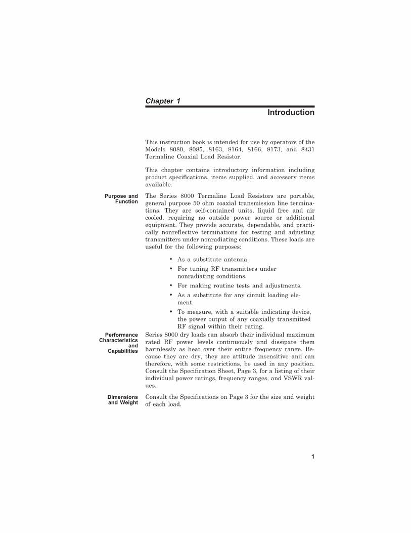
Figure 1
Model 8085 Outline Drawing
Chapter 2
Theory of Operation
General The resistive element, in these dry Termaline Loads, is indi-vidually selected for its accuracy, and enclosed in a heatsink housing. The housing is specially contoured inside toprovide the load with its unusually low reflection character-istics throughout its entire frequency range. The housingsfor the 25, 50, 100, and 150 Watt models are deeply slottedand painted black with a lusterless finish to improve theirheat dissipation. Models 8173 and 8431 are fabricated withsheet metal fins to more efficiently meet their higher heatdissipation requirements.
5
Bird Model 8000 Series Termaline Coaxial Load Resistor
6
Chapter 3
Installation
General These loads may be used for portable operation or fixed in-stallation. The Models 8080, 8085 and 8164 are, in general,light enough to be attached directly to the mating RF con-nector of another device such as a Bird Thruline Wattmeteror simply set on the workbench like the Models 8166, 8173,and 8431. Attach the load resistor as close as possible to thetransmitter’s output and use only suitable connectors. Tryto connect direct to minimize cable length and avoid the useof adapters as much as possible. The Model 8166, because ofits weight, has a provision for special mounting. The hous-ing has four tapped mounting holes on one side. They are1/2 inch (13 mm) deep for 8-32 screws and arranged in a6-3/8 x 1-3/4 inch (162 x 44.4 mm) rectangle. The Model8431, mounted horizontally, will dissipate up to 500 Watts,and mounted vertically, up to 600 Watts. Model 8173 shouldbe operated only in a horizontal position.
The Model 8163 Termaline Load Resistor is identical to theModel 8164 load electrically and physically except formounting holes. The Model 8163 load resistor has fourmounting holes with Heli-Coil stainless steel inserts to ac-commodate 8-32 mounting screws. These mounting holesare located two on the lower front face of the unit and twoon the lower rear face.
MountingLocation
Allow at least six inches of clearance around these units topermit an unimpeded access of natural convection of air foradequate heat dissipation. Place the loads to permit theshortest possible cable length between the unit and thetransmitting equipment.
7
Bird Model 8000 Series Termaline Coaxial Load Resistor
8
Chapter 4
Operating Instructions
Use andFunction of
Controls
These loads, being passive devices, have no indicators or op-erating controls.
InitialAdjustments
No initial adjustments are required other than to connectthe load to the RF source by means of a coaxial cableequipped with a suitable matching connector plug.
Start-Up Connect these loads to the transmitting equipment undertest with 50 ohm coaxial cable where necessary (RG-8A/U,RG-9/U, RG-213/U or equal) equipped with a suitable plugwhich mates with the RF input connector of the load. Afterthe load has been connected to the transmitter, proceed ac-cording to the transmitter manufacturer’s instructions.When reconnecting the antenna, it may be necessary toslightly readjust the transmitter due to possible differencesin VSWR between the load and the antenna system.
NormalOperation
CAUTIONDo not operate these loads continuously above their
maximum power rating. Load failure will result.
Having no indicators or operating controls, these loads re-quire no special operating procedures or surveillance whenthe stated performance limits are not exceeded.
OperationUnder
Emergency,Adverse or
AbnormalConditions
These units will sustain an input moderately greater thantheir maximum rated power for short periods of time. Suchloading must be spaced at reasonable intervals to allow suf-ficient time for cooling to a safe temperature. Apply the ex-cessive power for a few minutes at most and allow at least ahalf hour for adequate cooling before reapplying power. Be-cause of the excessive heat generated by overloading, touchthe load with caution to avoid painful burns.
Shutdown These loads, being passive devices, have no operating con-trols to be turned off. Their source of RF power must beturned off instead.
9
EmergencyShutdown
WARNINGNever attempt to disconnect RF equipment from thetransmission line while RF power is being applied.
Leaking RF energy is a potential health hazard.
Turn off the RF power at its source.
Bird Model 8000 Series Termaline Coaxial Load Resistor
10
Chapter 5
Maintenance
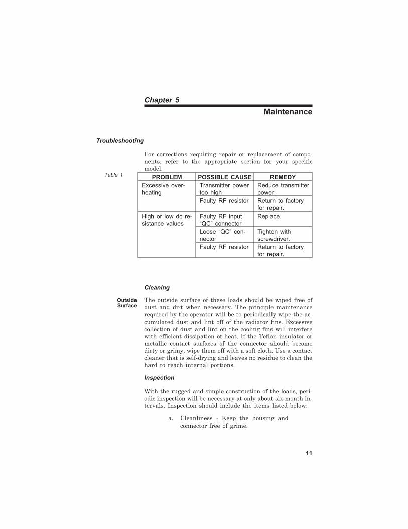
Troubleshooting
For corrections requiring repair or replacement of compo-nents, refer to the appropriate section for your specificmodel.
Cleaning
OutsideSurface
The outside surface of these loads should be wiped free ofdust and dirt when necessary. The principle maintenancerequired by the operator will be to periodically wipe the ac-cumulated dust and lint off of the radiator fins. Excessivecollection of dust and lint on the cooling fins will interferewith efficient dissipation of heat. If the Teflon insulator ormetallic contact surfaces of the connector should becomedirty or grimy, wipe them off with a soft cloth. Use a contactcleaner that is self-drying and leaves no residue to clean thehard to reach internal portions.
Inspection
With the rugged and simple construction of the loads, peri-odic inspection will be necessary at only about six-month in-tervals. Inspection should include the items listed below:
a. Cleanliness - Keep the housing andconnector free of grime.
11
PROBLEM POSSIBLE CAUSE REMEDY
Excessive over-
heating
Transmitter power
too high
Reduce transmitter
power.
Faulty RF resistor Return to factory
for repair.
High or low dc re-
sistance values
Faulty RF input
“QC” connector
Replace.
Loose “QC” con-
nector
Tighten with
screwdriver.
Faulty RF resistor Return to factory
for repair.
Table 1
b. Inspect the load for completeness andgeneral condition of the equipment.
c. A Troubleshooting Chart lists the com-monly encountered problems, theirpossible causes and remedies. Use thischart as a guide when analyzingsymptoms.
Preventive Maintenance
Due to the basic simplicity of construction, the major re-quirement for preventive maintenance is to keep the equip-ment clean, particularly the radiator fins. It is important tomaintain the heat transfer efficiency of the cooling fins.
RF Assembly Test
DC Resistance Check the condition of these load resistors by accurate mea-surement of the dc resistance between the inner and outerconductors of the RF input connector. Use a resistancebridge or ohmmeter with an accuracy of one percent orbetter at 50 ohms for this purpose. The measured resistanceshould be a nominal 50 ohms. For greater accuracy the re-sistance of the load should be carefully checked prior to useat ambient room temperature. This resistance value shouldbe recorded and used as a reference. Subsequent resistancemeasurements should not deviate more than two percentfrom this value.
Disassembly
Except for the “QC” connector, “SQC” on Model 8431, thereis no disassembly possible with these loads. To change theconnector use the following procedure.
RF Connector The connector is a “QC” design which permits easy inter-change with the use of only a screwdriver. This process doesnot interfere with the essential coaxial continuity of the loadresistor RF input. For replacement, proceed as follows:
a. Remove the four 8-32 x 5/16 inch panhead machine screws from the cornersof the RF connector.
b. Pull the connector straight out of itssocket.
Bird Model 8000 Series Termaline Coaxial Load Resistor
12
Reassembly
RF Connector To install a new connector, reverse the procedures in para-graph RF Connector, Disassembly. Be sure that the project-ing center pin on the connector is carefully engaged andproperly seated with the mating socket of the load resistorinput.
Repairs
WARNINGThis product contains a resistor substrate made of
beryllium oxide. This is a potentially toxic ceramic andmay be harmful to your health. Beryllia oxide must be
disposed of in accordance with the legal statutesdealing with hazardous material.
Do not attempt to repair this unit, but return to BIRDELECTRONIC CORPORATION.
Due to the unitized nature of the construction, these loadsare not field repairable other than replacement of the “QC”connector.
Repairs beyond what is covered in this instruction book willrequire return of the equipment to Bird Electronic Corpora-tion for service. Please consult the factory.
CustomerService
Any maintenance or service procedure beyond scope of thoseprovided in this section should be referred to a qualified ser-vice center. Bird Electronic Corporation maintains completerepair and calibration facilities at the following addresses:
For the location of the sales office nearest you, give us a callor visit our Web site at
http://www.bird-electronic.com
Storage No special preparations for storage are necessary other thanto cover the equipment to keep out dust and dirt. Storethese units in a dry and dust-free environment where theambient temperature will remain within the -40°C to +45°C(-40°F to +113°F) working range of the loads.
Shipment
RF Connector
Wrap the RF connector with padding and tape securely inplace. Pack and brace the load in a suitable shipping con-tainer; a corrugated paper box should suffice.
Replacement Parts List
Models 8080, 8085, 8164, 8166, and 8173 use “QC” connec-tors only.
Available QC Type Connectors
N-Female 4240-062 LT-Female 4240-018
N-Male 4240-063 LT-Male 4240-012
HN-Female 4240-268 C-Female 4240-100
HN-Male 4240-278 C-Male 4240-110
LC-Female 4240-031 UHF-Female 4240-050
LC-Male 4240-025 UHF-Male 4240-179
7/8" EIA Air Line 4240-002
Model 8431 uses “SQC” small connectors only.
N-Female 4100-014
M-Male 4100-015
UHF-Female 4100-017
UHF-Male 4100-021
C-Female 4100-045
Bird Model 8000 Series Termaline Coaxial Load Resistor
14
LIMITED WARRANTY
All products manufactured by Seller are warranted to be free from defects inmaterial and workmanship for a period of one (1) year, unless otherwise spec-ified, from date of shipment and to conform to applicable specifications, draw-ings, blueprints and/or samples. Seller’s sole obligation under thesewarranties shall be to issue credit, repair or replace any item or part thereofwhich is proved to be other than as warranted; no allowance shall be madefor any labor charges of Buyer for replacement of parts, adjustment or re-pairs, or any other work, unless such charges are authorized in advance bySeller.
If Seller’s products are claimed to be defective in material or workmanship ornot to conform to specifications, drawings, blueprints and/or samples, Sellershall, upon prompt notice thereof, either examine the products where theyare located or issue shipping instructions for return to Seller (transporta-tion-charges prepaid by Buyer). In the event any of our products are provedto be other than as warranted, transportation costs (cheapest way) to andfrom Seller’s plant, will be borne by Seller and reimbursement or credit willbe made for amounts so expended by Buyer. Every such claim for breach ofthese warranties shall be deemed to be waived by Buyer unless made in writ-ing within ten (10) days from the date of discovery of the defect. The abovewarranties shall not extend to any products or parts thereof which have beensubjected to any misuse or neglect, damaged by accident, rendered defectiveby reason of improper installation or by the performance of repairs or alter-ations outside of our plant, and shall not apply to any goods or parts thereoffurnished by Buyer or acquired from others at Buyer’s request and/or toBuyer’s specifications. In addition, Seller’s warranties do not extend to thefailure of tubes, transistors, fuses and batteries, or to other equipment andparts manufactured by others except to the extent of the original manufac-turer’s warranty to Seller.
The obligations under the foregoing warranties are limited to the preciseterms thereof. These warranties provide exclusive remedies, expressly in lieuof all other remedies including claims for special or consequential damages.SELLER NEITHER MAKES NOR ASSUMES ANY OTHER WARRANTYWHATSOEVER, WHETHER EXPRESS, STATUTORY, OR IMPLIED, IN-CLUDING WARRANTIES OF MERCHANTABILITY AND FITNESS, ANDNO PERSON IS AUTHORIZED TO ASSUME FOR SELLER ANY OBLIGA-TION OR LIABILITY NOT STRICTLY IN ACCORDANCE WITH THEFOREGOING.
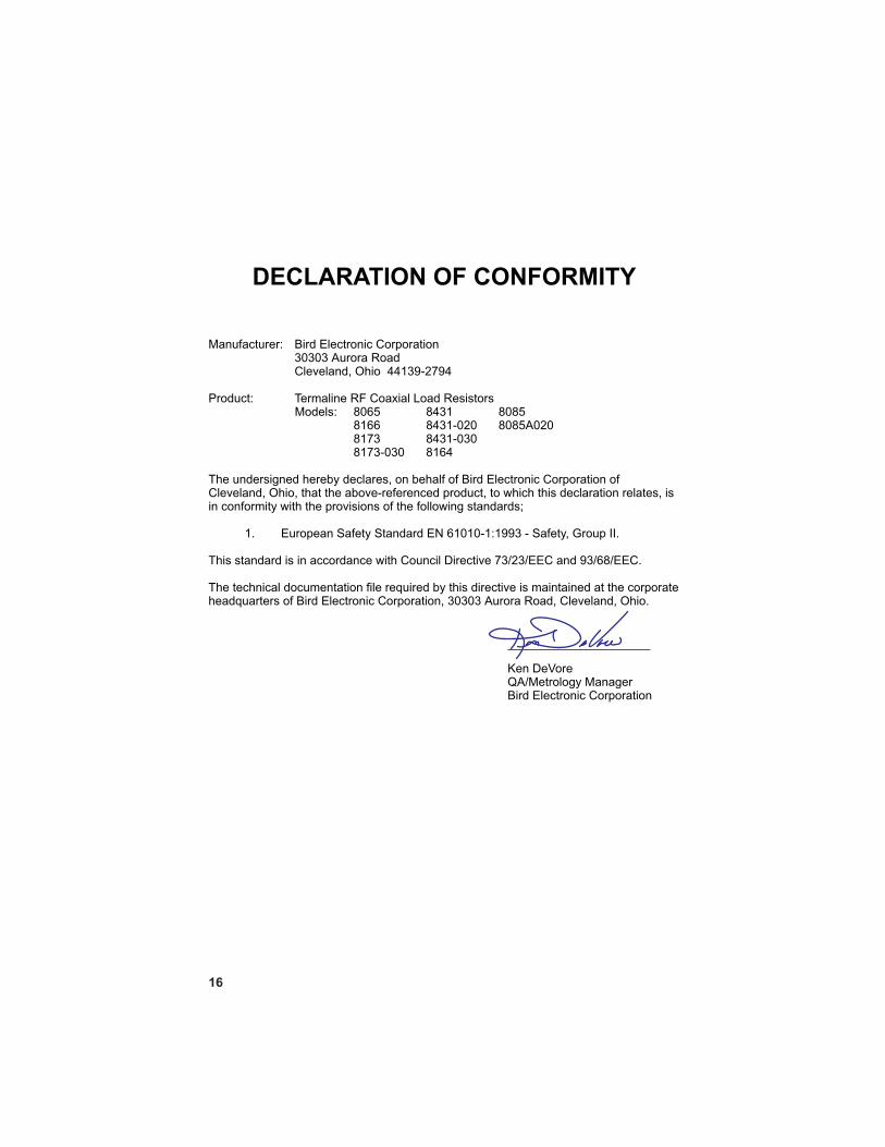
The undersigned hereby declares, on behalf of Bird Electronic Corporation ofCleveland, Ohio, that the above-referenced product, to which this declaration relates, isin conformity with the provisions of the following standards;
1. European Safety Standard EN 61010-1:1993 - Safety, Group II.
This standard is in accordance with Council Directive 73/23/EEC and 93/68/EEC.
The technical documentation file required by this directive is maintained at the corporateheadquarters of Bird Electronic Corporation, 30303 Aurora Road, Cleveland, Ohio.
Ken DeVoreQA/Metrology ManagerBird Electronic Corporation