174
MAB 104B-14/24 Instruction book High speed separator Product No. 881241-08-17/1 Book No. 9027982-02 Rev. 3
MAB 104B-14/24
Instruction book
High speed separator
Product No. 881241-08-17/1Book No. 9027982-02 Rev. 3

Published By:Alfa Laval Tumba ABSE-147 80 Tumba, Sweden
Telephone: +46 8 530 650 00Telefax: +46 8 530 310 40
The original instructions are in English
© Alfa Laval Tumba AB 02 October 2018
This publication or any part there of may not be reproduced or transmitted by any process or means without prior written permission of Alfa Laval Tumba AB.

Contents
1 Read this first 7
2 Safety instructions 9
2.1 Warning signs in text 14
2.2 Recycling Information 15
2.3 Requirements of personnel 16
2.4 Remote start 16
3 Separator basics 17
3.1 Basic principles of separation 18
3.2 Overview 22
3.3 Separating function 23
3.4 Mechanical function 30
3.5 Definitions 34
4 Operating instructions 35
4.1 Operating routine 36
4.2 Cleaning the bowl 44
5 Service instructions 47
5.1 Periodic maintenance 49
5.2 Maintenance Logs 52
5.3 MS - Check points 57
5.4 Cleaning 72
5.5 When changing oil 76
5.6 Common maintenance directions 77
5.7 Lifting instructions 83
6 Dismantling/Assembly 85
6.1 General 86
6.2 Dismantling 87
3
6.3 Assembly 98
6.4 Feed and discharge pumps 108
6.5 Frame feet 118
7 Trouble-tracing 119
7.1 Trouble tracing procedure 121
7.2 Mechanical function 121
7.3 Purification faults 127
7.4 Clarification faults 129
8 Technical reference 131
8.1 Product description 133
8.2 Technical data 136
8.3 Basic size drawing, separator without pump 139
8.4 Basic size drawing, separator with pump and no heater 140
8.5 Basic size drawing, separator with pump and heater 141
8.6 Connection list, (with pump and no heater / without pump) 142
8.7 Connection list,(pump and heater) 143
8.8 Interface description 144
8.9 Lubricants 147
8.10 Drawings 157
8.11 Electric motor 166
8.12 Storage and installation 167
4
nstruction manuals gs before installation, maintenance.
ctions can result in
clear only foreseeable conditions ings are given, therefore, for
ended usage of the machine and its
Read and understand iand observe the warninoperation, service and
Not following the instruserious accidents.
In order to make the informationhave been considered. No warnsituations arising from the uninttools.
5

6

1 Read this first
S00
6801
1
This manual is designed for operators and service engineers working with the Alfa Laval separator MAB 104B-14/24.
For information concerning the function of the separator, see ‘‘3 Separator basics” on page 17 and ‘‘4 Operating instructions” on page 35.
If the separator has been delivered and installed by Alfa Laval as part of a processing system, this manual is a part of the System Manual. In this case, study carefully all the instructions in the System Manual.
In addition to this Instruction book a Spare Parts Catalogue, SPC is supplied.
This Instruction book consists of:
Safety instructions
Pay special attention to the safety instructions for the separator. Not following the safety instructions can cause accidents resulting in damage to equipment and serious injury to personnel.
Separator basics
Read this chapter if you are not familiar with this type of separator.
Operating instructions
This chapter contains operating instructions for the separator only.
7

1 Read this first
Service instructions
This chapter gives instructions for daily checks, cleaning, oil changes, servicing and check points.
Dismantling / Assembly
This chapter contains step-by-step instructions for dismantling and assembly of the separator for service and repair.
Trouble-tracing
Refer to this chapter if the separator functions abnormally.
If the separator has been installed as part of a processing system always refer to the Trouble-tracing part of the System Manual first.
Technical reference
This chapter contains technical data concerning the separator and drawings.
Installation
General information on installation planning.
Lifting instruction.
8

2 Safety instructions
G00
1042
1S
0151
211
The centrifuge includes parts that rotate at high speed. This means that:
Kinetic energy is high
Great forces are generated
Stopping time is long
Manufacturing tolerances are extremely fine. Rotating parts are carefully balanced to reduce undesired vibrations that can cause a breakdown. Material properties have been considered carefully during design to withstand stress and fatigue.
The separator is designed and supplied for a specific separation duty (type of liquid, rotational speed, temperature, density etc.) and must not be used for any other purpose.
Incorrect operation and maintenance can result in unbalance due to build-up of sediment, reduction of material strength, etc., that subsequently could lead to serious damage and/or injury.
The following basic safety instructions therefore apply:
Use the separator only for the purpose and parameter range specified by Alfa Laval.
Strictly follow the instructions for installation, operation and maintenance.
Ensure that personnel are competent and have sufficient knowledge of maintenance and operation, especially concerning emergency stopping procedures.
Use only Alfa Laval genuine spare parts and the special tools supplied.
9
2 Safety instructions
S01
512F
1S
0151
2N1
kPa m /h3
3o
C
Hz
kg/m
r/min
S01
512P
1
50Hz
60Hz
S01
512L
1S
0151
241
A
(MAX 25 )
S01
512G
1S
0151
2H1
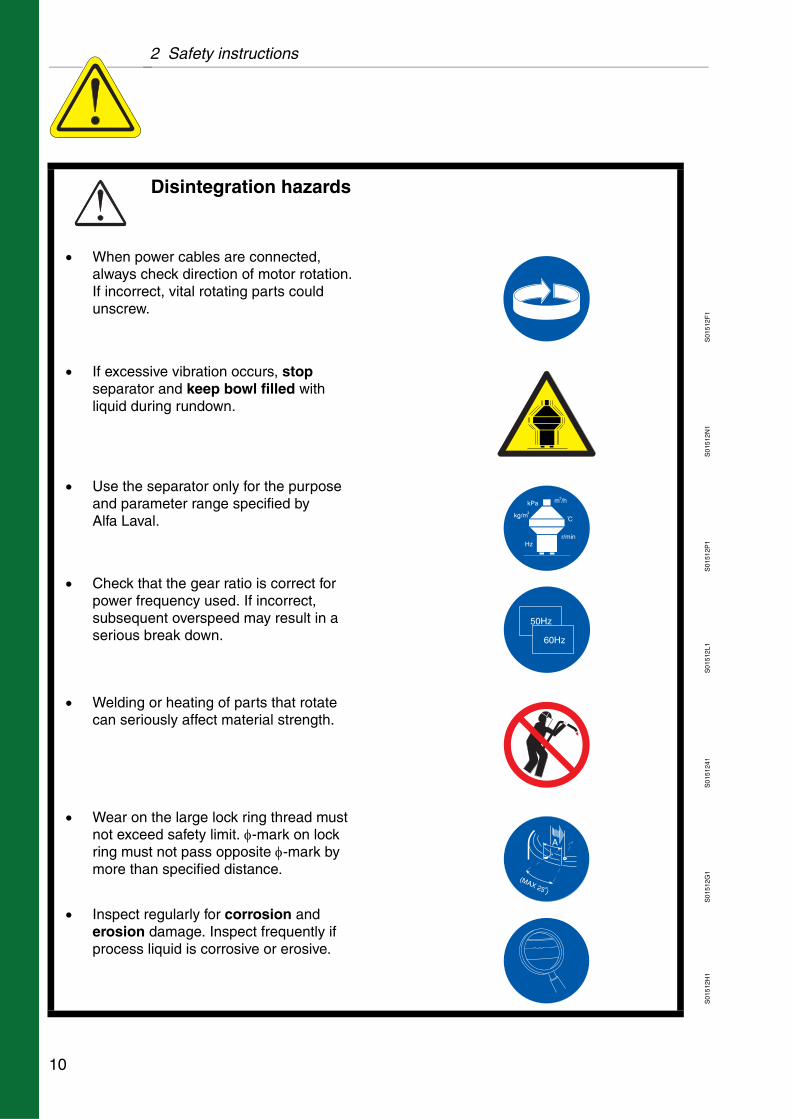
Disintegration hazards
When power cables are connected, always check direction of motor rotation. If incorrect, vital rotating parts could unscrew.
If excessive vibration occurs, stop separator and keep bowl filled with liquid during rundown.
Use the separator only for the purpose and parameter range specified by Alfa Laval.
Check that the gear ratio is correct for power frequency used. If incorrect, subsequent overspeed may result in a serious break down.
Welding or heating of parts that rotate can seriously affect material strength.
Wear on the large lock ring thread must not exceed safety limit. -mark on lock ring must not pass opposite -mark by more than specified distance.
Inspect regularly for corrosion and erosion damage. Inspect frequently if process liquid is corrosive or erosive.
10

2 Safety instructions
S01
5126
1S
0151
2O1
S01
5127
1
Entrapment hazards
Do NOT stand on the separator or parts of.
Entrapment hazards
Make sure that rotating parts have come to a complete standstill before starting any dismantling work.If there is no braking function the run down time can exceed two hours.
To avoid accidental start, switch off and lock power supply before starting any dismantling work.Assemble the machine completely before start. All covers and guards must be in place.
Electrical hazard
Follow local regulations for electrical installation and earthing (grounding).
To avoid accidental start, switch off and lock power supply before starting any dismantling work.
11
2 Safety instructions
S01
512M
1S
0151
2Y1
S01
5129
1S
0151
2A1
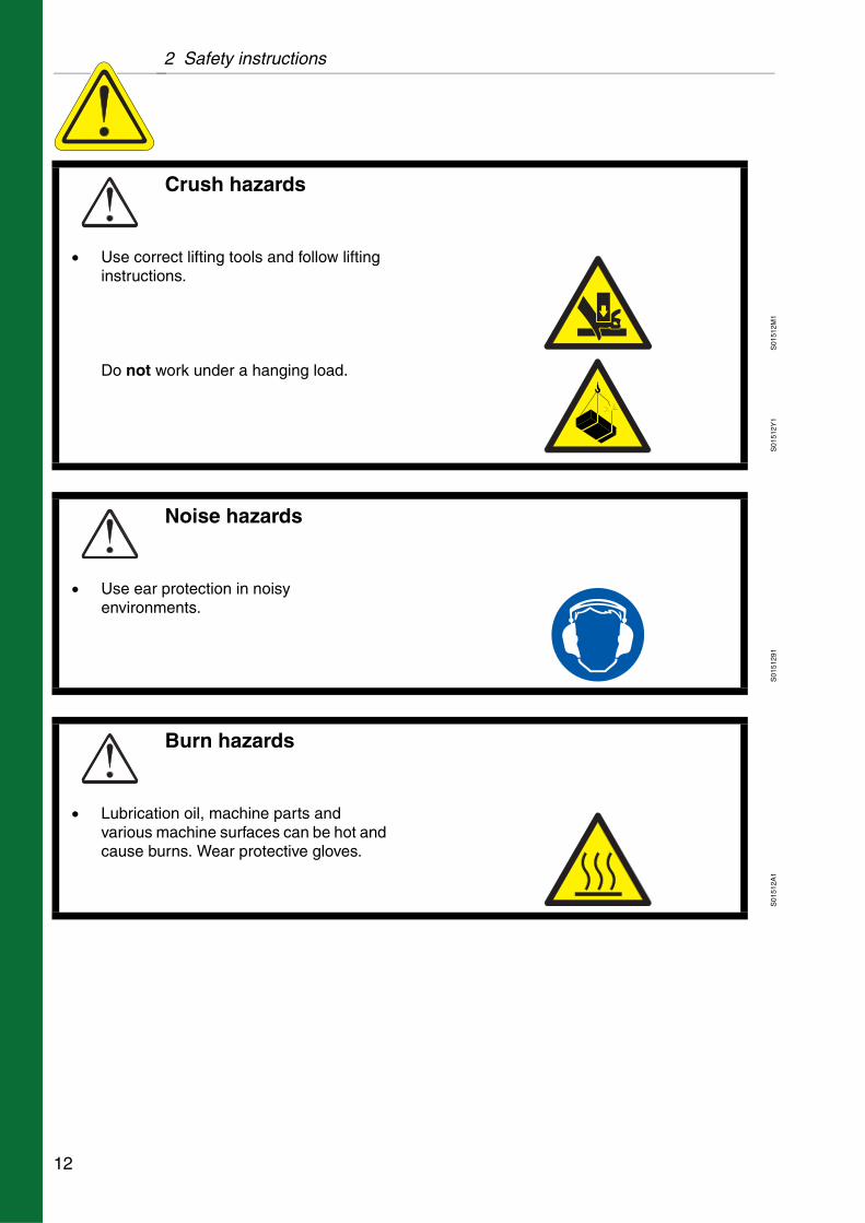
Crush hazards
Use correct lifting tools and follow lifting instructions.Do not work under a hanging load.
Noise hazards
Use ear protection in noisy environments.
Burn hazards
Lubrication oil, machine parts and various machine surfaces can be hot and cause burns. Wear protective gloves.
12

2 Safety instructions
S01
512D
1S
0151
2B1
S01
512C
1S
0151
2V1
Skin irritation hazards
When using chemical cleaning agents, make sure you follow the general rules and suppliers recommendation regarding ventilation, personnel protection etc.
Use of lubricants in various situations.
Cut hazards
Sharp edges, especially on bowl discs and threads can cause cuts.Wear protective gloves.
Flying objects
Risk for accidental release of snap rings and springs when dismantling and assembly. Wear safety goggles.
Health hazard
Risk for unhealthy dust when handling friction blocks/pads. Use a dust mask to make sure not to inhale any dust.
13
2 Safety instructions
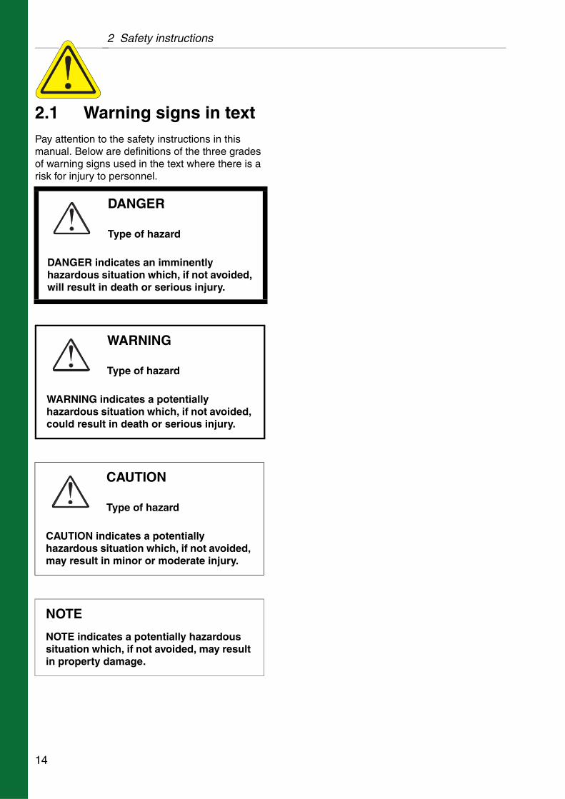
2.1 Warning signs in textPay attention to the safety instructions in this manual. Below are definitions of the three grades of warning signs used in the text where there is a risk for injury to personnel.
DANGER
Type of hazard
DANGER indicates an imminently hazardous situation which, if not avoided, will result in death or serious injury.
WARNING
Type of hazard
WARNING indicates a potentially hazardous situation which, if not avoided, could result in death or serious injury.
CAUTION
Type of hazard
CAUTION indicates a potentially hazardous situation which, if not avoided, may result in minor or moderate injury.
NOTE
NOTE indicates a potentially hazardous situation which, if not avoided, may result in property damage.
14

2 Safety instructions
2.2 Recycling Information
Unpacking
Packing material consists of wood, plastics, cardboard boxes and in some cases metal straps.
Wood and cardboard boxes can be reused, recycled or used for energy recovery.
Plastics should be recycled or burnt at a licensed waste incineration plant.
Metal straps should be sent for material recycling.
Maintenance
During maintenance oil and wear parts in the machine are replaced.
Oil must be taken care of in agreement with local regulations.
Rubber and plastics should be burnt at a licensed waste incineration plant. If not available they should be disposed to a suitable licensed land fill site.
Bearings and other metal parts should be sent to a licensed handler for material recycling.
Seal rings and friction linings should be disposed to a licensed land fill site. Check your local regulations.
Worn out or defected electronic parts should be sent to a licensed handler for material recycling.
Scrapping
At the end of use, the equipment must be recycled according to relevant local regulations.
Besides the equipment itself, any hazardous residues from the process liquid must be taken into consideration and dealt with in a proper manner. When in doubt, or in the absence of local regulations, please contact your local Alfa Laval sales company.
15

2 Safety instructions
2.3 Requirements of personnel
Only skilled or instructed persons are allowed to operate the machine, e.g. operating and maintenance staff.
Skilled person: A person with technical knowledge or sufficient experience to enable him or her to perceive risks and to avoid hazards which electricity/mechanics can create.
Instructed person: A person adequately advised or supervised by a skilled person to enable him or her to perceive risks and to avoid hazards which electricity/mechanics can create.
In some cases special skilled personnel may need to be hired, like electricians and others. In some of these cases the personnel has to be certified according to local regulations with experience of similar types of work.
2.4 Remote startIf the separator is operated from a remote position, from where it can neither be seen nor heard, the power isolation device shall be equipped with an interlocking device. This is to prevent a remote start command which could result in some liquid being fed to the separator when it is shut down for service.
The first start after the separator has been taken apart or has been standing still for a long time shall always be locally manually supervised.
16

3 Separator basics
Contents
3.1 Basic principles of separation 18
3.1.1 Factors influencing the separation result 19
3.2 Overview 22
3.3 Separating function 23
3.3.1 Purification 24
3.3.2 Purifier bowl 25
3.3.3 Liquid seal 26
3.3.4 Position of interface - gravity disc 26
3.3.5 Clarification 28
3.4 Mechanical function 30
3.4.1 Main parts 30
3.4.2 Inlet and outlet 31
3.4.3 Mechanical power transmission 32
3.4.4 Brake 32
3.4.5 Sensors and indicators 33
3.5 Definitions 34
17
3.1 Basic principles of separation 3 Separator basics
G00
1071
1
Sedimentation by gravity
G00
1081
1
Sedimentation in a settling tank, with outlets making it possible to separate the lighter liquid parts from the heavier
G00
1091
1
The centrifugal solution
3.1 Basic principles of separation
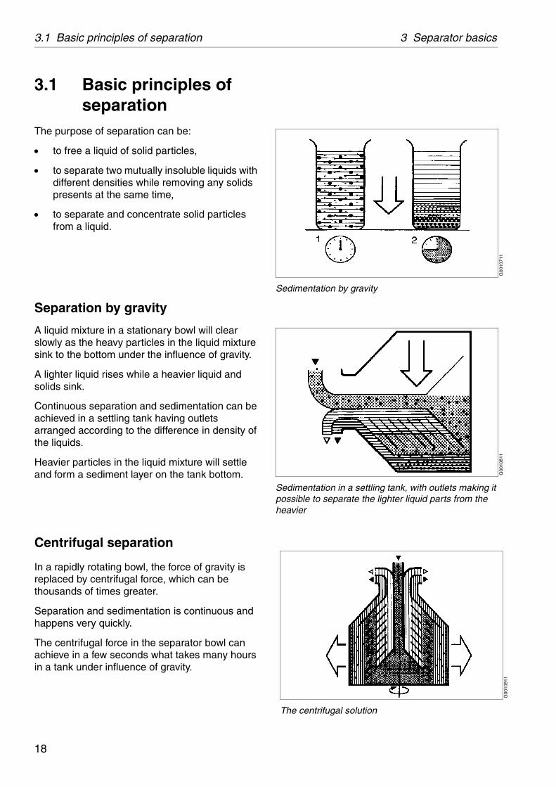
The purpose of separation can be:
to free a liquid of solid particles,
to separate two mutually insoluble liquids with different densities while removing any solids presents at the same time,
to separate and concentrate solid particles from a liquid.
Separation by gravity
A liquid mixture in a stationary bowl will clear slowly as the heavy particles in the liquid mixture sink to the bottom under the influence of gravity.
A lighter liquid rises while a heavier liquid and solids sink.
Continuous separation and sedimentation can be achieved in a settling tank having outlets arranged according to the difference in density of the liquids.
Heavier particles in the liquid mixture will settle and form a sediment layer on the tank bottom.
Centrifugal separation
In a rapidly rotating bowl, the force of gravity is replaced by centrifugal force, which can be thousands of times greater.
Separation and sedimentation is continuous and happens very quickly.
The centrifugal force in the separator bowl can achieve in a few seconds what takes many hours in a tank under influence of gravity.
18
3 Separator basics 3.1 Basic principles of separation
G00
1102
1
High viscosity (with low temperature)
G00
1112
1
Low viscosity (with high temperature)
G00
1122
1
High density (with low temperature)
G00
1132
1
Low density (with high temperature)
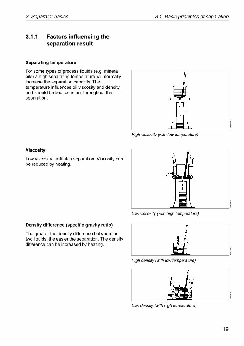
3.1.1 Factors influencing the separation result
Separating temperature
For some types of process liquids (e.g. mineral oils) a high separating temperature will normally increase the separation capacity. The temperature influences oil viscosity and density and should be kept constant throughout the separation.
Viscosity
Low viscosity facilitates separation. Viscosity can be reduced by heating.
Density difference (specific gravity ratio)
The greater the density difference between the two liquids, the easier the separation. The density difference can be increased by heating.
19

3.1 Basic principles of separation 3 Separator basics
2 1
A
B
m³/h
μm
G06
1331
1
Influence of size and shape
G06
0121
1
Sludge accumulation
Phase proportions
An increased quantity of water in an oil will influence the separating result through the optimum transporting capacity of the disc stack. An increased water content in the oil can be compensated by reducing the throughput in order to restore the optimum separating efficiency.
Size and shape of particles
The round and smooth particle (A) is more easily separated out than the irregular one (B).
Rough treatment, for instance in pumps, may cause a splitting of the particles resulting in slower separation. Larger particles (1) are more easily separated than smaller ones (2) even if they have the same density.
The throughput
The throughput sets the time allowed for the separation of water and sediment from the oil. A better separation result can often be achieved by reducing the throughput, i.e. by increasing the settling time.
Sludge space - sludge content
Sediment will accumulate on the inside periphery of the bowl. When the sludge space is filled up the flow inside the bowl is influenced by the sediment and thereby reducing the separating efficiency. In such cases the time between cleaning should be reduced to suit these conditions.
20
3 Separator basics 3.1 Basic principles of separation
S00
6861
1
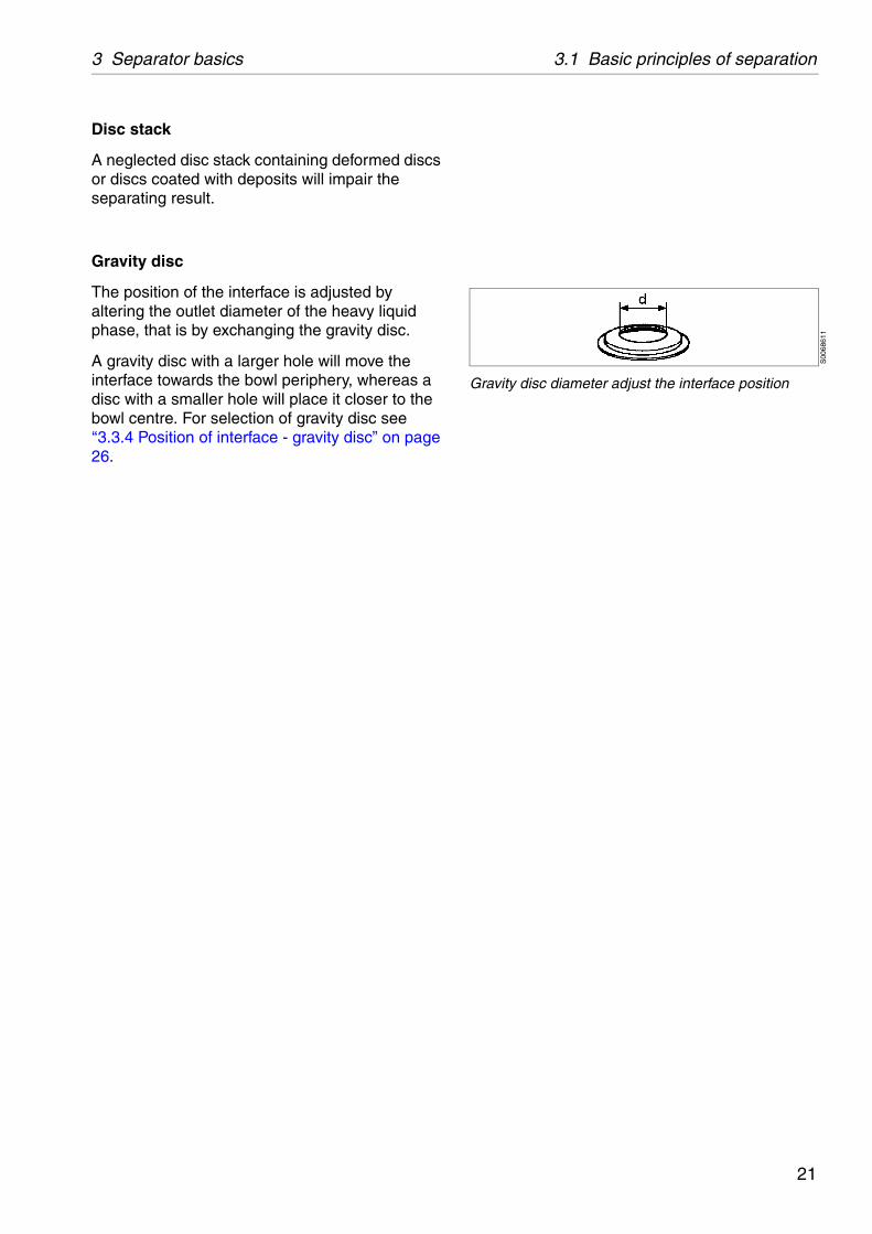
Gravity disc diameter adjust the interface position
Disc stack
A neglected disc stack containing deformed discs or discs coated with deposits will impair the separating result.
Gravity disc
The position of the interface is adjusted by altering the outlet diameter of the heavy liquid phase, that is by exchanging the gravity disc.
A gravity disc with a larger hole will move the interface towards the bowl periphery, whereas a disc with a smaller hole will place it closer to the bowl centre. For selection of gravity disc see ‘‘3.3.4 Position of interface - gravity disc” on page 26.
21
3.2 Overview 3 Separator basics
3.2 OverviewThe separator comprises a processing part and a driving part. It is driven by an electric motor.
Mechanically, the separator machine frame is composed of a bottom part and a collecting cover. The motor is flanged to the frame. The frame feet have vibration damping.
The bottom part of the separator contains the horizontal driving device, driving shaft with coupling, a worm gear and a vertical spindle.
The bottom part also contains an oil bath for the worm gear, a brake and a revolution counter, indicating speed.
The collecting cover contains the processing parts of the separator, the inlet and outlets and piping.
The liquid is cleaned in the separator bowl. This is fitted on the upper part of the vertical spindle and rotates at high speed inside the space formed by the collecting cover.
All connections have standardised numbers. These numbers are used in the connection list and the basic size drawing which can be found in chapter ‘‘8 Technical reference” on page 131.
22
3 Separator basics 3.3 Separating function
G06
1321
1
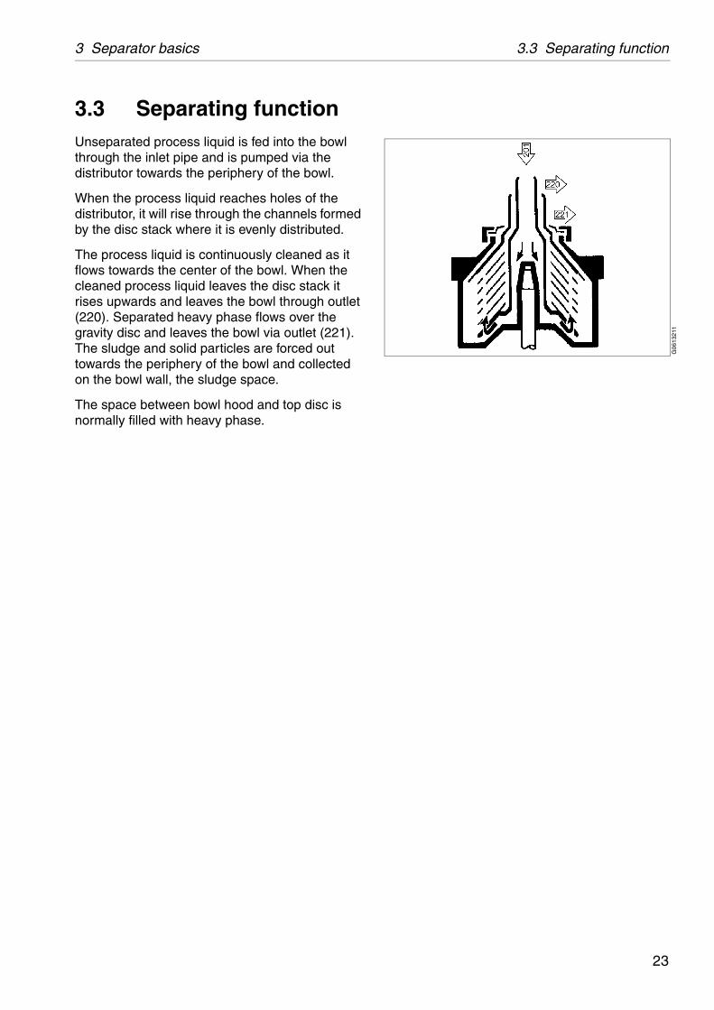
3.3 Separating functionUnseparated process liquid is fed into the bowl through the inlet pipe and is pumped via the distributor towards the periphery of the bowl.
When the process liquid reaches holes of the distributor, it will rise through the channels formed by the disc stack where it is evenly distributed.
The process liquid is continuously cleaned as it flows towards the center of the bowl. When the cleaned process liquid leaves the disc stack it rises upwards and leaves the bowl through outlet (220). Separated heavy phase flows over the gravity disc and leaves the bowl via outlet (221). The sludge and solid particles are forced out towards the periphery of the bowl and collected on the bowl wall, the sludge space.
The space between bowl hood and top disc is normally filled with heavy phase.
23
3.3 Separating function 3 Separator basics
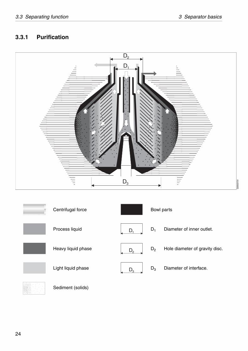
Bowl parts
D1 Diameter of inner outlet.
D2 Hole diameter of gravity disc.
D3 Diameter of interface.
D1
D2
D3
G05
0373
1
D1
D2
D3
3.3.1 Purification
Centrifugal force
Process liquid
Heavy liquid phase
Light liquid phase
Sediment (solids)
24
3 Separator basics 3.3 Separating function
G05
8901
1
Purifier bowl
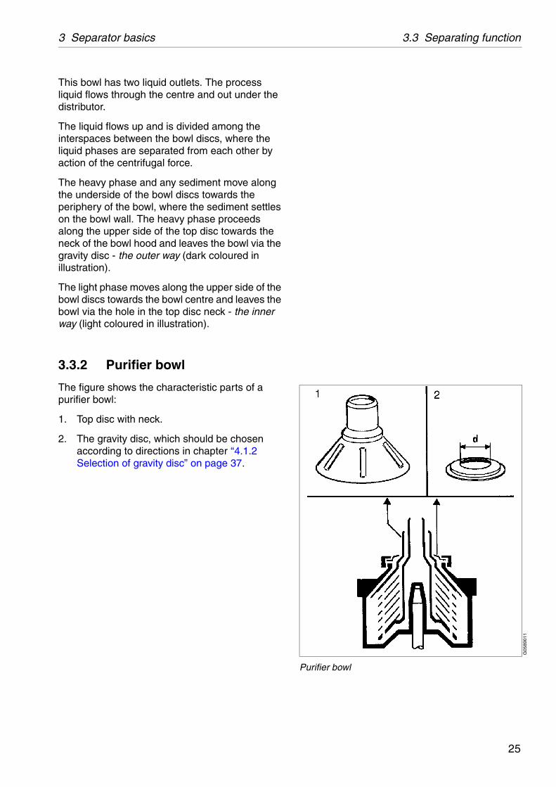
This bowl has two liquid outlets. The process liquid flows through the centre and out under the distributor.
The liquid flows up and is divided among the interspaces between the bowl discs, where the liquid phases are separated from each other by action of the centrifugal force.
The heavy phase and any sediment move along the underside of the bowl discs towards the periphery of the bowl, where the sediment settles on the bowl wall. The heavy phase proceeds along the upper side of the top disc towards the neck of the bowl hood and leaves the bowl via the gravity disc - the outer way (dark coloured in illustration).
The light phase moves along the upper side of the bowl discs towards the bowl centre and leaves the bowl via the hole in the top disc neck - the inner way (light coloured in illustration).
3.3.2 Purifier bowl
The figure shows the characteristic parts of a purifier bowl:
1. Top disc with neck.
2. The gravity disc, which should be chosen according to directions in chapter ‘‘4.1.2 Selection of gravity disc” on page 37.
25
3.3 Separating function 3 Separator basics
G06
1201
1G
0600
711
Exchange of gravity disc
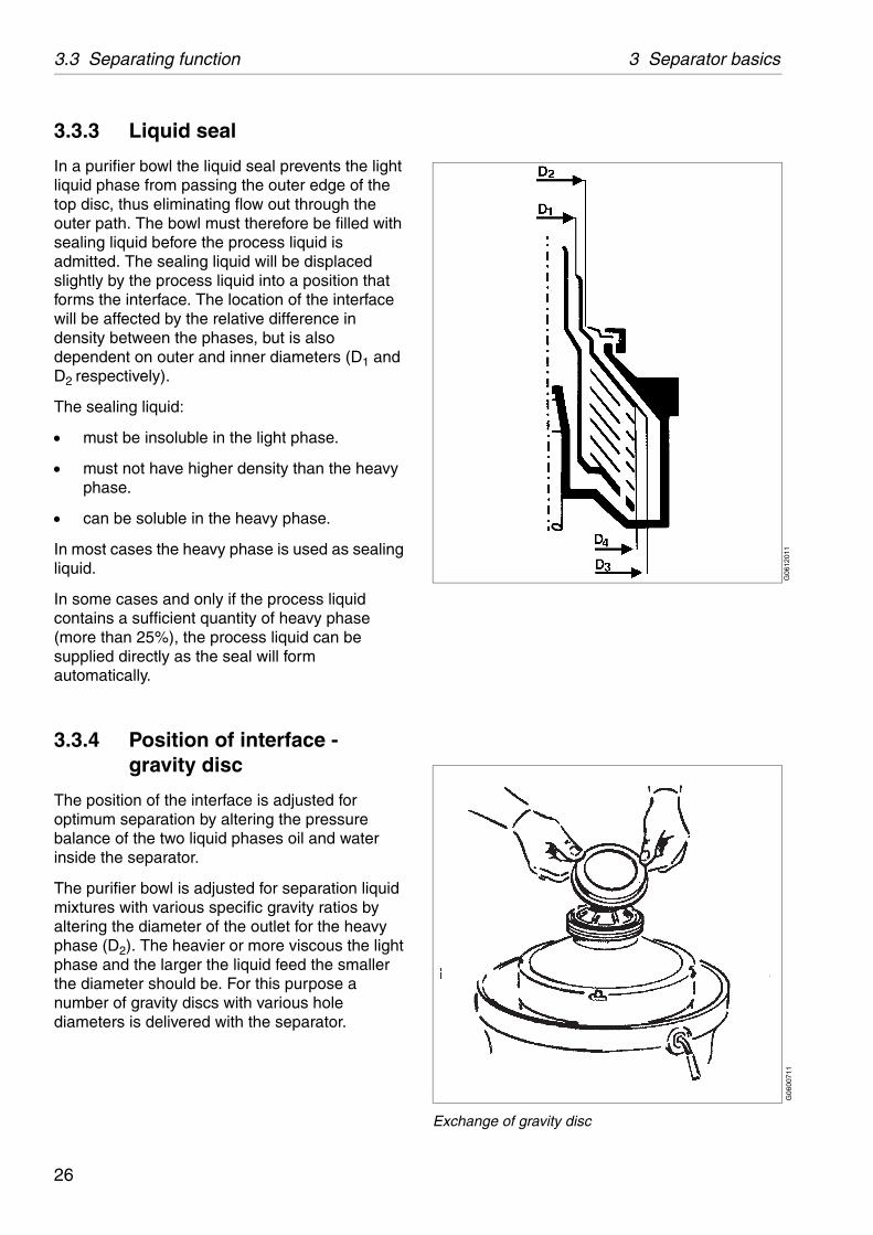
3.3.3 Liquid seal
In a purifier bowl the liquid seal prevents the light liquid phase from passing the outer edge of the top disc, thus eliminating flow out through the outer path. The bowl must therefore be filled with sealing liquid before the process liquid is admitted. The sealing liquid will be displaced slightly by the process liquid into a position that forms the interface. The location of the interface will be affected by the relative difference in density between the phases, but is also dependent on outer and inner diameters (D1 and D2 respectively).
The sealing liquid:
must be insoluble in the light phase.
must not have higher density than the heavy phase.
can be soluble in the heavy phase.
In most cases the heavy phase is used as sealing liquid.
In some cases and only if the process liquid contains a sufficient quantity of heavy phase (more than 25%), the process liquid can be supplied directly as the seal will form automatically.
3.3.4 Position of interface - gravity disc
The position of the interface is adjusted for optimum separation by altering the pressure balance of the two liquid phases oil and water inside the separator.
The purifier bowl is adjusted for separation liquid mixtures with various specific gravity ratios by altering the diameter of the outlet for the heavy phase (D2). The heavier or more viscous the light phase and the larger the liquid feed the smaller the diameter should be. For this purpose a number of gravity discs with various hole diameters is delivered with the separator.
26
3 Separator basics 3.3 Separating function
S00
6861
1
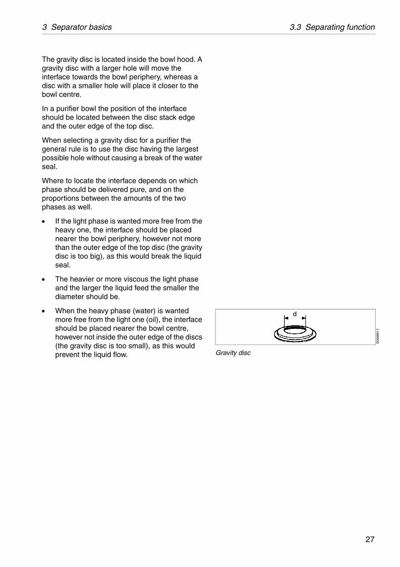
Gravity disc
The gravity disc is located inside the bowl hood. A gravity disc with a larger hole will move the interface towards the bowl periphery, whereas a disc with a smaller hole will place it closer to the bowl centre.
In a purifier bowl the position of the interface should be located between the disc stack edge and the outer edge of the top disc.
When selecting a gravity disc for a purifier the general rule is to use the disc having the largest possible hole without causing a break of the water seal.
Where to locate the interface depends on which phase should be delivered pure, and on the proportions between the amounts of the two phases as well.
If the light phase is wanted more free from the heavy one, the interface should be placed nearer the bowl periphery, however not more than the outer edge of the top disc (the gravity disc is too big), as this would break the liquid seal.
The heavier or more viscous the light phase and the larger the liquid feed the smaller the diameter should be.
When the heavy phase (water) is wanted more free from the light one (oil), the interface should be placed nearer the bowl centre, however not inside the outer edge of the discs (the gravity disc is too small), as this would prevent the liquid flow.
27
3.3 Separating function 3 Separator basics
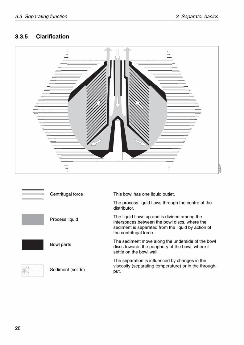
is bowl has one liquid outlet.
e process liquid flows through the centre of the tributor.
e liquid flows up and is divided among the erspaces between the bowl discs, where the diment is separated from the liquid by action of centrifugal force.
e sediment move along the underside of the bowl cs towards the periphery of the bowl, where it ttle on the bowl wall.
e separation is influenced by changes in the cosity (separating temperature) or in the through-t.
G05
0371
1
3.3.5 Clarification
Centrifugal force Th
Thdis
Thintsethe
Thdisse
Thvispu
Process liquid
Bowl parts
Sediment (solids)
28
3 Separator basics 3.3 Separating function
G05
8912
1
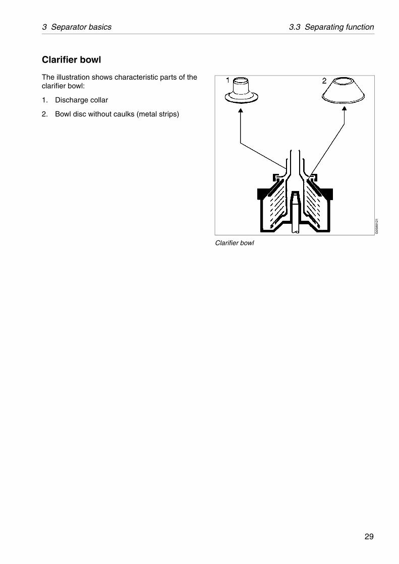
Clarifier bowl
Clarifier bowl
The illustration shows characteristic parts of the clarifier bowl:
1. Discharge collar
2. Bowl disc without caulks (metal strips)
29
3.4 Mechanical function 3 Separator basics
G06
8582
1
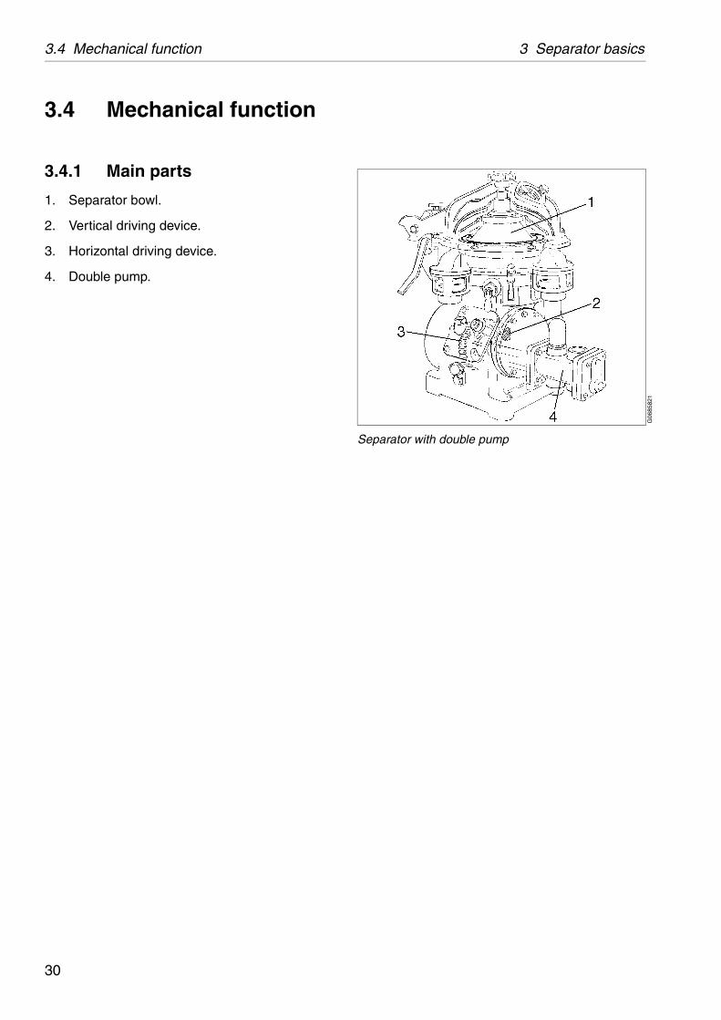
Separator with double pump
3.4 Mechanical function
3.4.1 Main parts
1. Separator bowl.
2. Vertical driving device.
3. Horizontal driving device.
4. Double pump.
30

3 Separator basics 3.4 Mechanical function
G06
2572
1
Separator with in- and outlet pump
G06
2582
1
Separator without pump
3.4.2 Inlet and outlet
The inlet and outlets consist of the following parts:
The inlet to pump (201.1).
The outlet from pump to heater (201.2).
The inlet from heater to separator (201.3).
The inlet for water seal (206).
The outlet for clean oil (220).
The outlet for water (221).
Drain of frame (460).
The inlet (201).
The inlet for water seal (206).
The outlet for clean oil (220).
The outlet for water (221).
Drain of frame (460).
See drawings and connection lists on pages 139 to 142.
31

3.4 Mechanical function 3 Separator basics
G02
4643
1
1. Bowl spindle2. Top bearing and spring casing3. Worm wheel4. Worm5. Friction coupling6. Worm wheel shaft
G06
0742
1
Applying (A) and releasing (B) of brake
3.4.3 Mechanical power transmission
The main parts of the power transmission between motor and bowl are illustrated in the figure.
The friction coupling ensures a gentle start and acceleration and at the same time prevents overloading of the worm gear and motor.
The worm gear has a ratio which increase the bowl speed several times compared with the motor speed. For correct ratio see chapter ‘‘8.2 Technical data” on page 136.
To reduce bearing wear and the transmission of bowl vibrations to the frame and foundation, the top bearing of the bowl spindle is mounted in a spring casing.
The worm wheel runs in a lubricating oil bath. The bearings on the spindle and the worm wheel shaft are lubricated by the oil splash produced by the rotating worm wheel.
3.4.4 Brake
The separator is equipped with a hand operated brake to be used when stopping the separator. The use of the brake reduces the retardation time of the bowl and critical speeds will therefore be quickly passed.
The brake lining acts on the outside of the bowl body.
32

3 Separator basics 3.4 Mechanical function
G02
4623
1
Revolution counter - speed indicator
G06
0271
1
Sight glass - oil level
3.4.5 Sensors and indicators
Revolution counter
A revolution counter indicates the speed of the separator and is driven from the worm wheel shaft. The correct speed is needed to achieve the best separating results and for reasons of safety. The number of revolutions on the revolution counter for correct speed is shown in chapter ‘‘8 Technical reference” on page 131. Refer to name plate for speed particulars.
Sight glass
The sight glass shows the oil level in the worm gear housing.
33
3.5 Definitions 3 Separator basics
let.
he intention of separating particles, normally lower density than the particles.
es the gravity disc in the separator bowl, in the e disc seals off the heavy phase (water) outlet in xists.
sed in kg/m3 at specified temperature, normally at
itioning the interface between the disc stack and . This disc is only used in purifier mode.
eavy phase (outer) and the light phase (inner) in
he separator bowl to prevent the light phase from eavy phase outlet, in purifier mode.
arator, including bottom part. Renewal of seals in eals and bearings in bottom part.
with the intention of separating two intermixed hases of different densities. Solids having a can be removed at the same time. The lighter major part of the mixture, shall be purified as far
.
the separator per time unit. Expressed in m3/h or
ment. Normally expressed in centistoke temperature
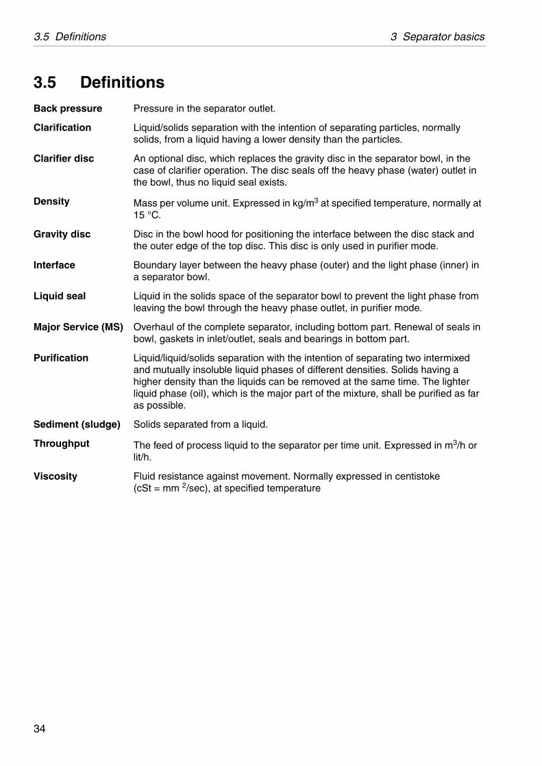
3.5 DefinitionsBack pressure Pressure in the separator out
Clarification Liquid/solids separation with tsolids, from a liquid having a
Clarifier disc An optional disc, which replaccase of clarifier operation. Ththe bowl, thus no liquid seal e
Density Mass per volume unit. Expres15 °C.
Gravity disc Disc in the bowl hood for posthe outer edge of the top disc
Interface Boundary layer between the ha separator bowl.
Liquid seal Liquid in the solids space of tleaving the bowl through the h
Major Service (MS) Overhaul of the complete sepbowl, gaskets in inlet/outlet, s
Purification Liquid/liquid/solids separationand mutually insoluble liquid phigher density than the liquidsliquid phase (oil), which is theas possible.
Sediment (sludge) Solids separated from a liquid
Throughput The feed of process liquid to lit/h.
Viscosity Fluid resistance against move(cSt = mm 2/sec), at specified
34
4 Operating instructions
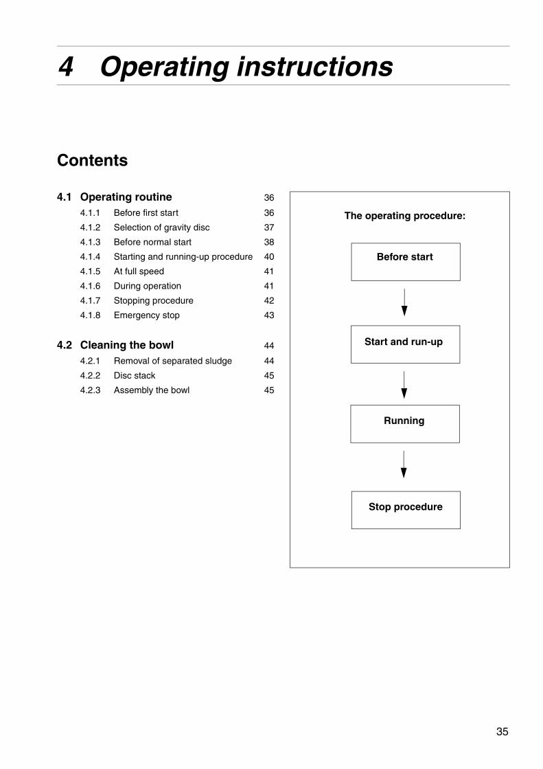
Before start
Start and run-up
Running
Stop procedure
The operating procedure:
Contents
4.1 Operating routine 36
4.1.1 Before first start 36
4.1.2 Selection of gravity disc 37
4.1.3 Before normal start 38
4.1.4 Starting and running-up procedure 40
4.1.5 At full speed 41
4.1.6 During operation 41
4.1.7 Stopping procedure 42
4.1.8 Emergency stop 43
4.2 Cleaning the bowl 44
4.2.1 Removal of separated sludge 44
4.2.2 Disc stack 45
4.2.3 Assembly the bowl 45
35

4.1 Operating routine 4 Operating instructions
G06
8581
1
Separator with double pump
4.1 Operating routineThese instructions are related only to the separator itself.
4.1.1 Before first start
Technical demands for connections and logical limitations for the separator is described in the chapter ‘‘8 Technical reference” on page 131 and the documents:
a. Technical data
b. Basic size drawing
c. Connection list
d. Interface description
e. Foundation drawing
Before first start the following checkpoint must be checked:
Motors equipped with regreasing nipples: When starting the motor for the first time, or after long storage of the motor, apply the specified quantity of grease until new grease is forced out of the grease outlet.
Ensure the machine is installed correctly and that feed-lines and drains have been flushed clean.
Fill oil in the gear housing. Fill up to the middle of the sightglass. Use the correct grade of oil. The separator is delivered without oil in the worm gear housing. For grade and quality, see ‘‘8.9 Lubricants” on page 147.
NOTE
If there is a system manual, always follow the operating instructions of the system manual. If there is no system manual the instructions below are to be followed
36

4 Operating instructions 4.1 Operating routine
G05
8901
1
Separator bowl with top disc and gravity disc
4.1.2 Selection of gravity disc
The separator is delivered with a set of gravity discs. The diameter (d) of the gravity disc (2) sets the position of the interface in the separator. The separation efficiency can be optimized by selection of the correct diameter for each process. See ‘‘8.2.1 Selection of gravity disc with the nomograph” on page 137
37

4.1 Operating routine 4 Operating instructions
G05
9931
1
Check separator is assembled
S00
0982
1
Check pipe connections
G06
0021
1
Hook bolts for collecting cover
G06
0271
1
Check oil level
4.1.3 Before normal start
Check these points before every start.
1. Ensure the bowl is clean and that the separator is properly assembled.
2. Make sure that all inlet and outlet couplings and connections have been correctly made and are properly tightened to prevent leakage.
3. Check that the hooks and screws for the collecting cover are fully tightened.
4. Read the oil level. The middle of the sight glass indicates the minimum level. Refill if necessary. For grade and quality, see ‘‘8.9 Lubricants” on page 147.
38

4 Operating instructions 4.1 Operating routine
G06
0742
1
Release the brake by moving it from pos. A to B
S00
6881
1
5. Release the brake.
6. Make sure the direction of rotation of the motor and bowl corresponds to the sign on the frame.
39

4.1 Operating routine 4 Operating instructions
G02
4623
1
Direction of rotation
G06
0001
1
Smoke and odour
S00
5562
1
Vibration
4.1.4 Starting and running-up procedure
1. After starting the separator, visually check to be sure that the motor and separator have started to rotate.
2. Check the direction of rotation. The revolution counter should run counter-clockwise.
3. Be alert for unusual noises or conditions. Smoke and odour may occur at the start when friction pads are new.
4. Note the normal occurrence of critical speed vibration periods.
5. During start the current reaches a peak and then slowly drops to a low and stable value.For normal length of the start-up period see ‘‘8.2 Technical data” on page 136.
WARNING
Disintegration hazards
When excessive vibration occurs, stop separator and keep bowl filled with liquid during rundown.
The cause of the vibrations must be identified and corrected before the separator is restarted.
Excessive vibrations may be due to incorrect assembly or poor cleaning of the bowl.
40
4 Operating instructions 4.1 Operating routine
4.1.5 At full speed
1. If running the separator as a purifier, supply liquid (water) to form the liquid seal. Continue until liquid (water) flows out through the heavy phase (water) outlet. The liquid (water) should have the same temperature as the process liquid and be supplied quickly.
2. Close the liquid (water) feed.
3. Start the oil feed slowly to avoid breaking the water seal. Then fill the bowl as quickly as possible.
4. Adjust to desired throughput.
4.1.6 During operation
Do regular checks on:
feed inlet temperature (if applicable)
collecting tank level
sound/vibration of the separator
motor current.
41

4.1 Operating routine 4 Operating instructions
G06
0742
1
Pull the brake from position B to A
S00
5112
1
4.1.7 Stopping procedure
1. If running the separator as a purifier, feed sealing water.
2. Turn off the feed.
3. Stop the separator.
4. Pull the brake (A).
Wait until the separator has come to a complete standstill (2-5 minutes). Release the brake (B) when the separator is at standstill.
5. Manual cleaning should be carried out before next start up. See ‘‘4.2.1 Removal of separated sludge’’.
WARNING
Entrapment hazards
Make sure that rotating parts have come to a complete standstill before starting any dismantling work.
The revolution counter and the motor fan indicate if the separator is rotating or not.
42

4 Operating instructions 4.1 Operating routine
S00
0991
1
Emergency stop
4.1.8 Emergency stop
The emergency stop is always installed according to local safety regulations. It is often a button placed on the wall near the separator or on the control equipment.
If the separator begins to vibrate excessively during operation, stop it immediately by switching off the separator motor, e.g. by pushing the emergency stop button.
WARNING
Disintegration hazards
Evacuate the area around the separator. The separator may be hazardous when passing its critical speeds during the run-down.
NOTE
After an emergency stop the cause of the fault must be identified.
If all parts have been checked and the cause remains unclear, contact Alfa Laval for advice.
43
4.2 Cleaning the bowl 4 Operating instructions
G06
0121
1
Sludge accumulation
S00
5111
1
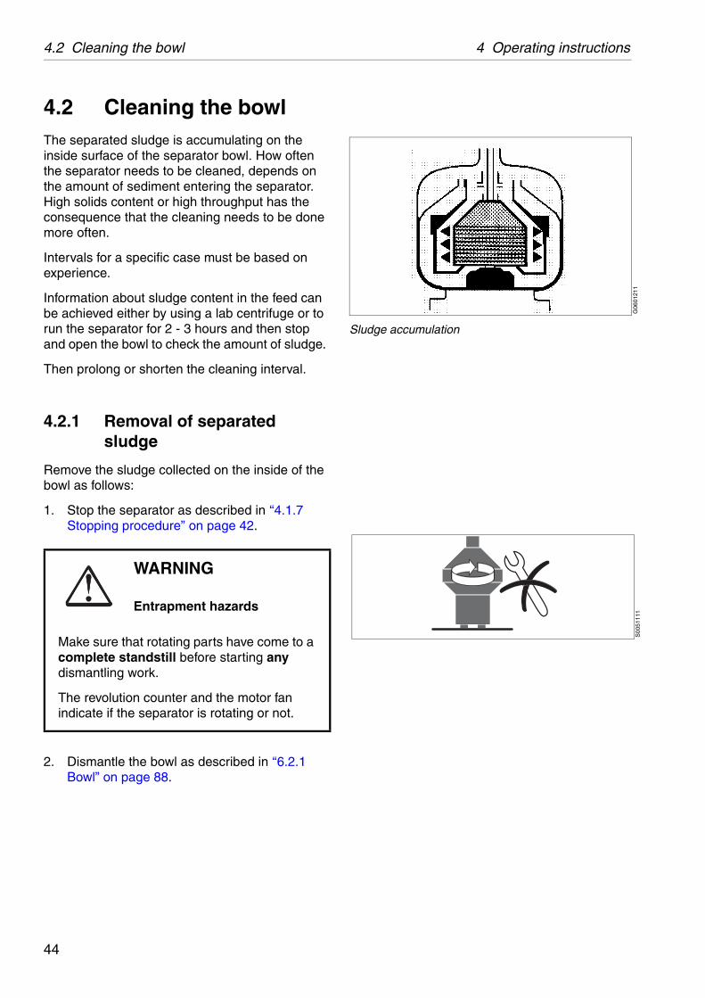
4.2 Cleaning the bowlThe separated sludge is accumulating on the inside surface of the separator bowl. How often the separator needs to be cleaned, depends on the amount of sediment entering the separator. High solids content or high throughput has the consequence that the cleaning needs to be done more often.
Intervals for a specific case must be based on experience.
Information about sludge content in the feed can be achieved either by using a lab centrifuge or to run the separator for 2 - 3 hours and then stop and open the bowl to check the amount of sludge.
Then prolong or shorten the cleaning interval.
4.2.1 Removal of separated sludge
Remove the sludge collected on the inside of the bowl as follows:
1. Stop the separator as described in ‘‘4.1.7 Stopping procedure” on page 42.
2. Dismantle the bowl as described in ‘‘6.2.1 Bowl” on page 88.
WARNING
Entrapment hazards
Make sure that rotating parts have come to a complete standstill before starting any dismantling work.
The revolution counter and the motor fan indicate if the separator is rotating or not.
44
4 Operating instructions 4.2 Cleaning the bowl
G06
0121
1
Bowl cleaning by “hurling”
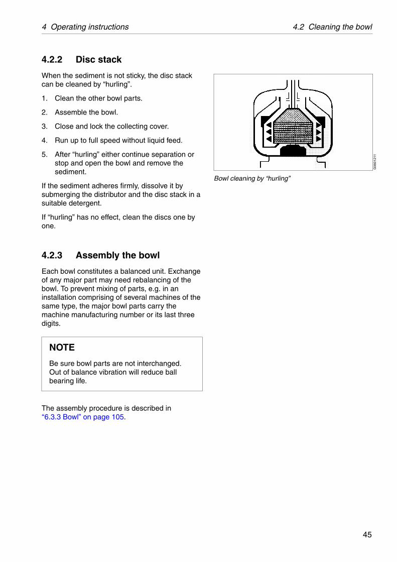
4.2.2 Disc stack
When the sediment is not sticky, the disc stack can be cleaned by “hurling”.
1. Clean the other bowl parts.
2. Assemble the bowl.
3. Close and lock the collecting cover.
4. Run up to full speed without liquid feed.
5. After “hurling” either continue separation or stop and open the bowl and remove the sediment.
If the sediment adheres firmly, dissolve it by submerging the distributor and the disc stack in a suitable detergent.
If “hurling” has no effect, clean the discs one by one.
4.2.3 Assembly the bowl
Each bowl constitutes a balanced unit. Exchange of any major part may need rebalancing of the bowl. To prevent mixing of parts, e.g. in an installation comprising of several machines of the same type, the major bowl parts carry the machine manufacturing number or its last three digits.
The assembly procedure is described in‘‘6.3.3 Bowl” on page 105.
NOTE
Be sure bowl parts are not interchanged.Out of balance vibration will reduce ball bearing life.
45
4.2 Cleaning the bowl 4 Operating instructions
G06
1239
1
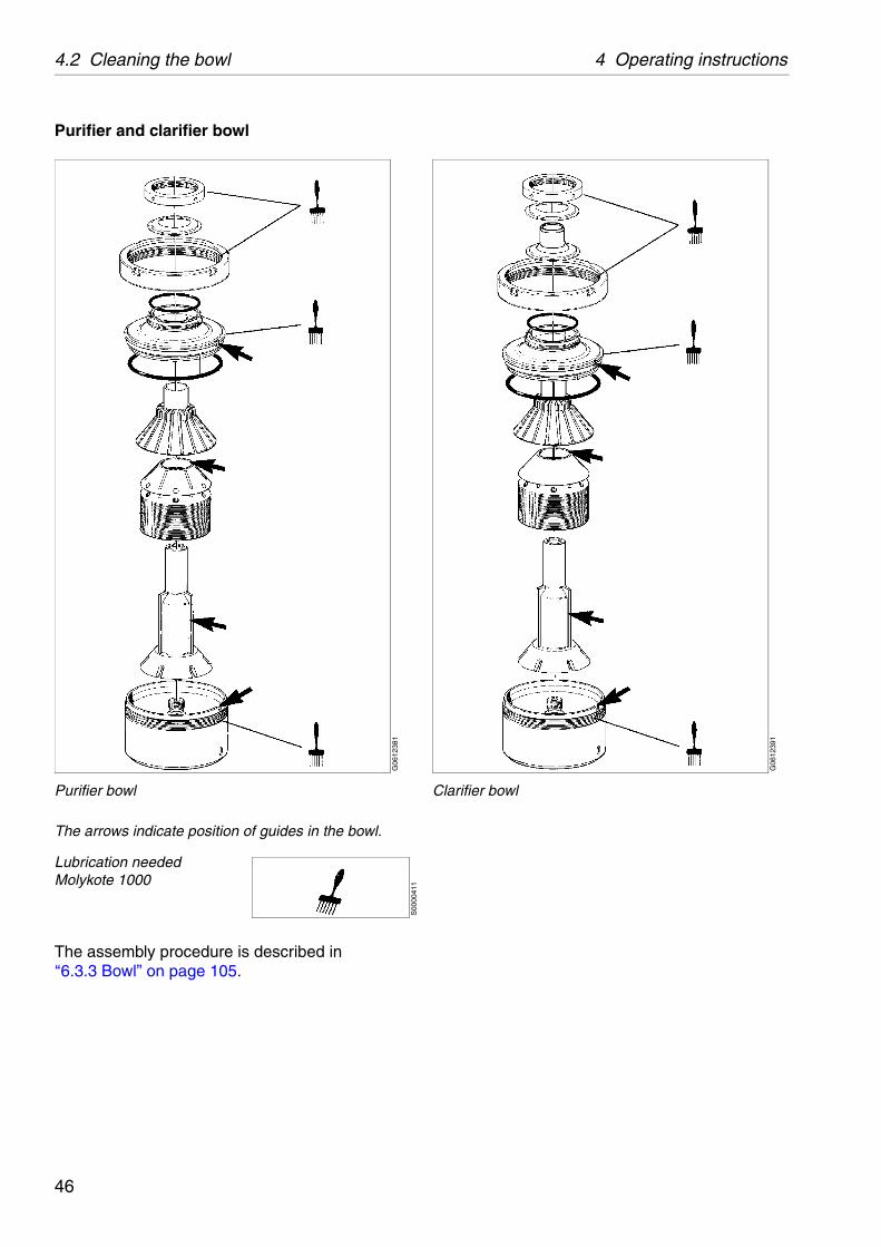
Clarifier bowl
Purifier and clarifier bowl
The arrows indicate position of guides in the bowl.
The assembly procedure is described in‘‘6.3.3 Bowl” on page 105.
Lubrication neededMolykote 1000
G06
1238
1
Purifier bowl
S00
0041
1
46
5 Service instructions
Contents
5.1 Periodic maintenance 49
5.1.1 Introduction 49
5.1.2 Maintenance intervals 49
5.1.3 Maintenance procedure 51
5.1.4 Service kits 51
5.2 Maintenance Logs 52
5.2.1 Daily checks 52
5.2.2 Oil change 53
5.2.3 IS - Intermediate Service 54
5.2.4 MS-Major Service 55
5.3 MS - Check points 57
5.3.1 Corrosion 57
5.3.2 Erosion 59
5.3.3 Cracks 60
5.3.4 Disc stack pressure 61
5.3.5 Lock ring; wear and damage 62
5.3.6 Radial wobble of bowl spindle 63
5.3.7 Height position of bowl / bowl spindle64
5.3.8 Bowl spindle cone and bowl body nave 65
5.3.9 Coupling disc of motor 66
5.3.10 Friction pads 67
5.3.11 Brake 68
5.3.12 Top bearing springs 69
5.3.13 Ball bearing housing 69
5.3.14 Worm wheel and worm; wear of teeth70
5.4 Cleaning 72
5.4.1 External cleaning 72
5.4.2 Cleaning agents 73
5.4.3 Cleaning of bowl discs 75
47

5 Service instructions
5.5 When changing oil 76
5.5.1 Oil change procedure 76
5.6 Common maintenance directions 77
5.6.1 Vibration 77
5.6.2 Ball and roller bearings 78
5.6.3 Friction coupling 80
5.6.4 Before shutdown 81
5.6.5 Before start-up 81
5.6.6 Lubrication of electric motor 82
5.7 Lifting instructions 83
48
5 Service instructions 5.1 Periodic maintenance
G06
0801
1
Periodic maintenance prevents stoppages
G05
9051
1
Maintenance log
5.1 Periodic maintenance
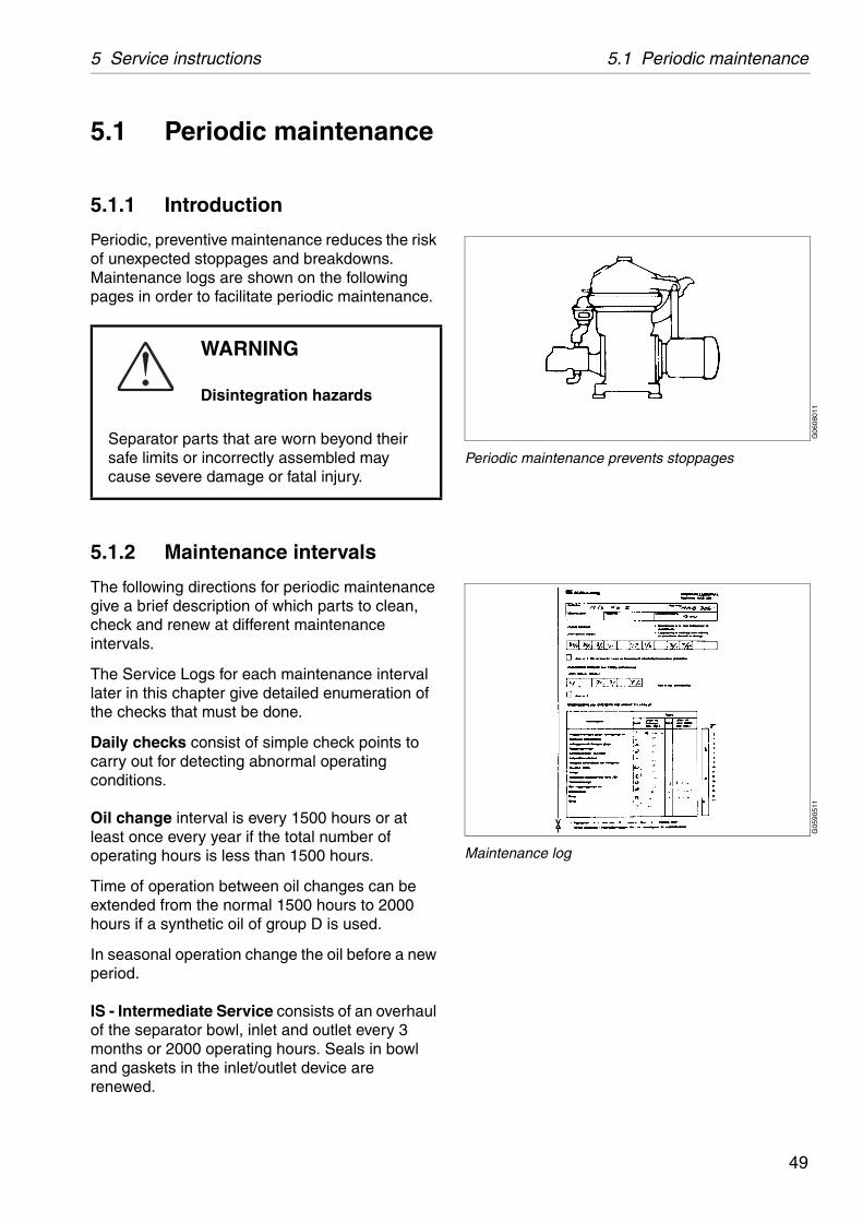
5.1.1 Introduction
Periodic, preventive maintenance reduces the risk of unexpected stoppages and breakdowns. Maintenance logs are shown on the following pages in order to facilitate periodic maintenance.
5.1.2 Maintenance intervals
The following directions for periodic maintenance give a brief description of which parts to clean, check and renew at different maintenance intervals.
The Service Logs for each maintenance interval later in this chapter give detailed enumeration of the checks that must be done.
Daily checks consist of simple check points to carry out for detecting abnormal operating conditions.
Oil change interval is every 1500 hours or at least once every year if the total number of operating hours is less than 1500 hours.
Time of operation between oil changes can be extended from the normal 1500 hours to 2000 hours if a synthetic oil of group D is used.
In seasonal operation change the oil before a new period.
IS - Intermediate Service consists of an overhaul of the separator bowl, inlet and outlet every 3 months or 2000 operating hours. Seals in bowl and gaskets in the inlet/outlet device are renewed.
WARNING
Disintegration hazards
Separator parts that are worn beyond their safe limits or incorrectly assembled may cause severe damage or fatal injury.
49
5.1 Periodic maintenance 5 Service instructions
r
edule
3-year Service
MS MSS IS IS IS IS IS IS IS
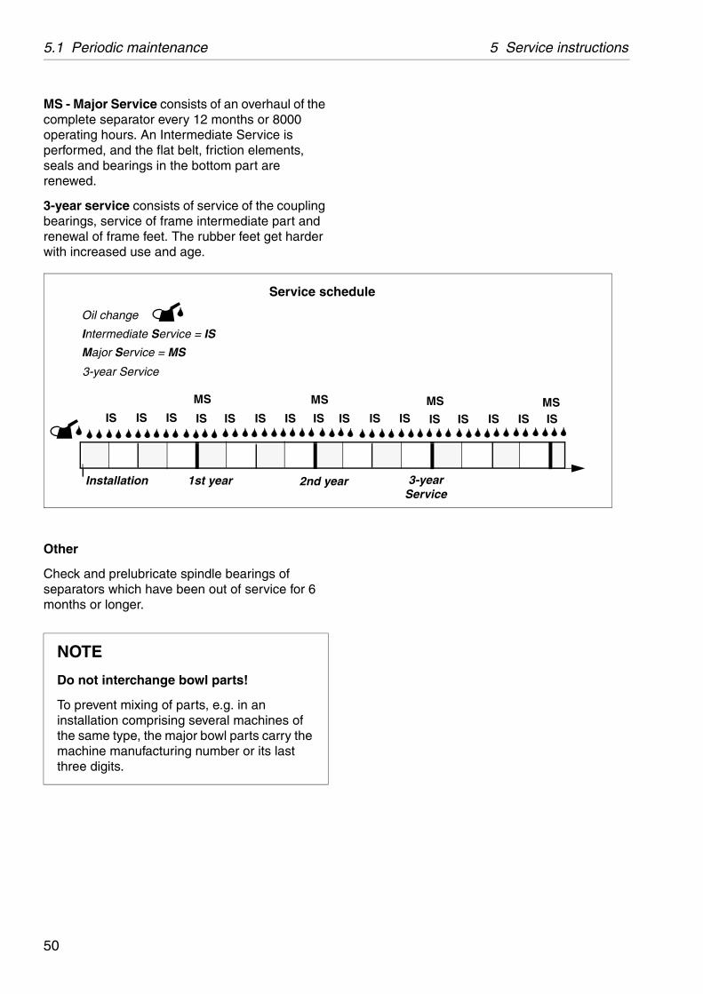
MS - Major Service consists of an overhaul of the complete separator every 12 months or 8000 operating hours. An Intermediate Service is performed, and the flat belt, friction elements, seals and bearings in the bottom part are renewed.
3-year service consists of service of the coupling bearings, service of frame intermediate part and renewal of frame feet. The rubber feet get harder with increased use and age.
Other
Check and prelubricate spindle bearings of separators which have been out of service for 6 months or longer.
NOTE
Do not interchange bowl parts!
To prevent mixing of parts, e.g. in an installation comprising several machines of the same type, the major bowl parts carry the machine manufacturing number or its last three digits.
2nd yea
Oil change
Intermediate Service = IS
Major Service = MS
Service sch
Installation 1st year
MS MS
IS IS IS IS IS IS IS IS I
3-year Service
50
5 Service instructions 5.1 Periodic maintenance
S00
2103
1
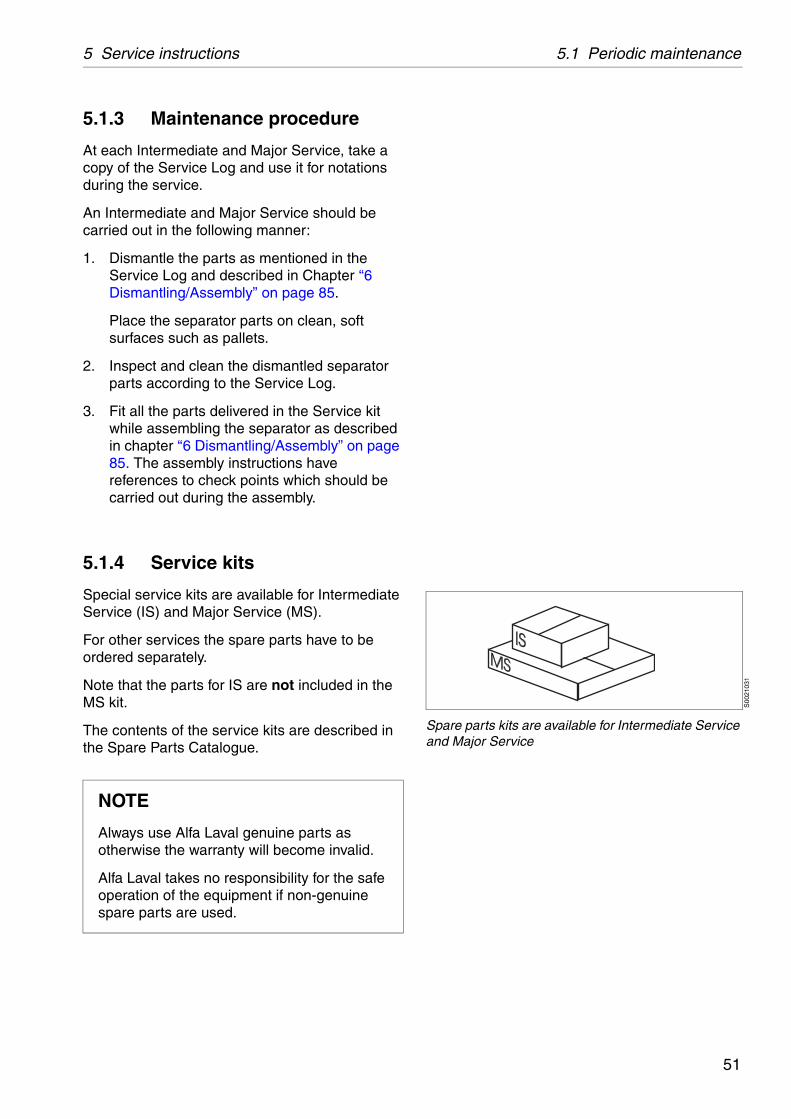
Spare parts kits are available for Intermediate Service and Major Service
5.1.3 Maintenance procedure
At each Intermediate and Major Service, take a copy of the Service Log and use it for notations during the service.
An Intermediate and Major Service should be carried out in the following manner:
1. Dismantle the parts as mentioned in the Service Log and described in Chapter ‘‘6 Dismantling/Assembly” on page 85.
Place the separator parts on clean, soft surfaces such as pallets.
2. Inspect and clean the dismantled separator parts according to the Service Log.
3. Fit all the parts delivered in the Service kit while assembling the separator as described in chapter ‘‘6 Dismantling/Assembly” on page 85. The assembly instructions have references to check points which should be carried out during the assembly.
5.1.4 Service kits
Special service kits are available for Intermediate Service (IS) and Major Service (MS).
For other services the spare parts have to be ordered separately.
Note that the parts for IS are not included in the MS kit.
The contents of the service kits are described in the Spare Parts Catalogue.
NOTE
Always use Alfa Laval genuine parts as otherwise the warranty will become invalid.
Alfa Laval takes no responsibility for the safe operation of the equipment if non-genuine spare parts are used.
51
5.2 Maintenance Logs 5 Service instructions
Page Notes
cover -
77
gear housing 53
-1)
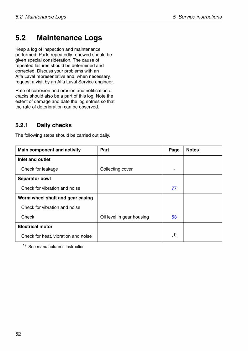
5.2 Maintenance LogsKeep a log of inspection and maintenance performed. Parts repeatedly renewed should be given special consideration. The cause of repeated failures should be determined and corrected. Discuss your problems with an Alfa Laval representative and, when necessary, request a visit by an Alfa Laval Service engineer.
Rate of corrosion and erosion and notification of cracks should also be a part of this log. Note the extent of damage and date the log entries so that the rate of deterioration can be observed.
5.2.1 Daily checks
The following steps should be carried out daily.
Main component and activity Part
Inlet and outlet
Check for leakage Collecting
Separator bowl
Check for vibration and noise
Worm wheel shaft and gear casing
Check for vibration and noise
Check Oil level in
Electrical motor
Check for heat, vibration and noise
1) See manufacturer’s instruction
52

5 Service instructions 5.2 Maintenance Logs
Page Notes
eel and worm 70
ar housing 53
5.2.2 Oil change
The oil change and check of worm gear should be carried out every 1500 * hours of operation.
* When using a group D oil, time of operation between oil changes can be extended from the normal 1500 hours to 2000 hours.
When the separator is running for short periods, the lubricating oil must be changed every 12 months even if the total number of operating hours is less than 1500 hours (2000 h).
In a new installation, or after replacement of gear, change the oil after 200 operating hours.
See chapter ‘‘8 Technical reference” on page 131 for further information.
Main component and activity Part
Worm wheel shaft and gear housing
Check Worm wh
Renew Oil * in ge
53

5.2 Maintenance Logs 5 Service instructions
ocal identification:
anufacture No./Year:
roduct No.: 881241-08-17
ignature:
kit (IS) and do the following activities.
Page Notes
nd frame hood –
–
–
75
–
lock ring and bowl 62
uide surface 62
erosion, cracks 57 - 60
mp 76
n motor –
–
l on hood 164
s and labels –
5.2.3 IS - Intermediate Service
Name of plant: L
Separator: MAB 104B-14/24 M
Total running hours: P
Date: S
Renew all parts included in the Intermediate Service
Main component and activity Part
Inlet and outlet, frame
Clean and inspect Housings a
Separator bowl
Clean and inspect Bowl hood
Top disc
Bowl discs
Distributor
Threads onbody
Check Galling of g
Corrosion,
Power transmission
Change Oil in oil su
Electrical motor
Lubrication (if nipples are fitted) See sign o
Vertical driving device
Lubricate Top bearing
Signs and labels on separator
Check attachment and legibility Safety labe
Other plate
54
5 Service instructions 5.2 Maintenance Logs
ocal identification:
anufacture No./Year:
roduct No.: 881241-08-17
ignature:
Page Notes
f inlet –
62
–
–
c –
75
–
–
57
59
60
pressure 61
d sealings –
el and worm 70
bble of worm wheel –
of coupling disc 66
housing 53
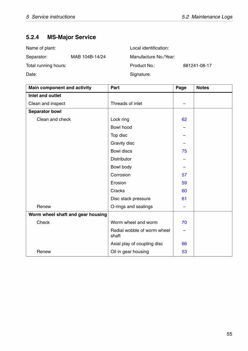
5.2.4 MS-Major Service
Name of plant: L
Separator: MAB 104B-14/24 M
Total running hours: P
Date: S
Main component and activity Part
Inlet and outlet
Clean and inspect Threads o
Separator bowl
Clean and check Lock ring
Bowl hood
Top disc
Gravity dis
Bowl discs
Distributor
Bowl body
Corrosion
Erosion
Cracks
Disc stack
Renew O-rings an
Worm wheel shaft and gear housing
Check Worm whe
Radial woshaft
Axial play
Renew Oil in gear
55
5.2 Maintenance Logs 5 Service instructions
le 65
–
g housing ns
63
bble of bowl spindle 63
gs and top bearing 65
d brake shoe 68
68
upling 80
ds 80
g 80
ampers 118
f coupling disc 66
–
el on collecting 164
Page Notes
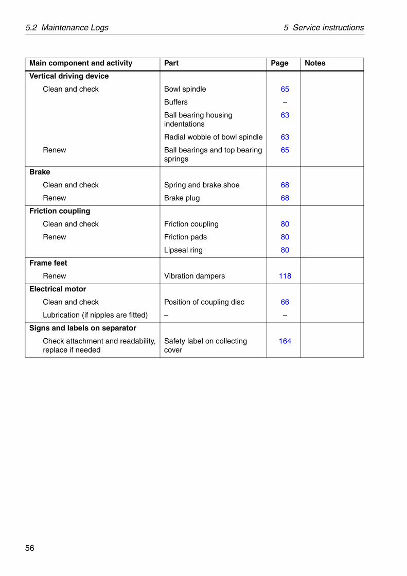
Vertical driving device
Clean and check Bowl spind
Buffers
Ball bearinindentatio
Radial wo
Renew Ball bearinsprings
Brake
Clean and check Spring an
Renew Brake plug
Friction coupling
Clean and check Friction co
Renew Friction pa
Lipseal rin
Frame feet
Renew Vibration d
Electrical motor
Clean and check Position o
Lubrication (if nipples are fitted) –
Signs and labels on separator
Check attachment and readability, replace if needed
Safety labcover
Main component and activity Part
56
5 Service instructions 5.3 MS - Check points
G05
8981
1
Main bowl parts
S00
2061
1
Corrosion forming a line
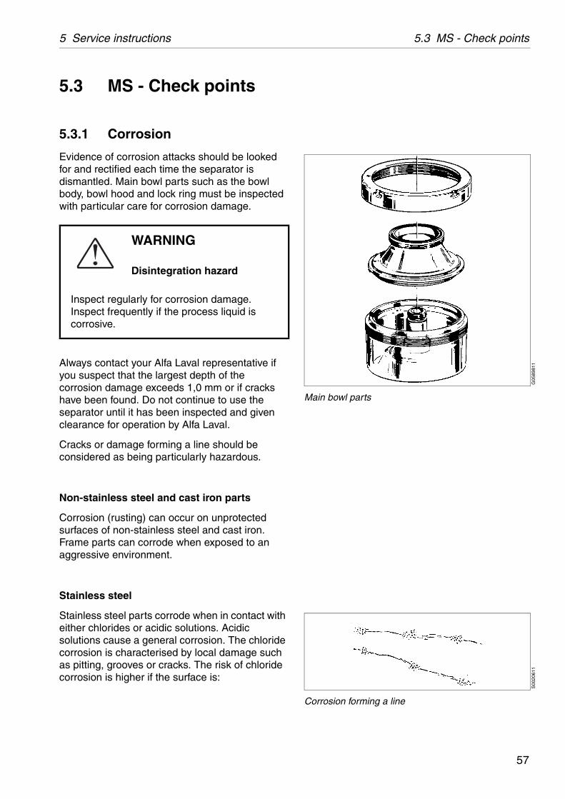
5.3 MS - Check points
5.3.1 Corrosion
Evidence of corrosion attacks should be looked for and rectified each time the separator is dismantled. Main bowl parts such as the bowl body, bowl hood and lock ring must be inspected with particular care for corrosion damage.
Always contact your Alfa Laval representative if you suspect that the largest depth of the corrosion damage exceeds 1,0 mm or if cracks have been found. Do not continue to use the separator until it has been inspected and given clearance for operation by Alfa Laval.
Cracks or damage forming a line should be considered as being particularly hazardous.
Non-stainless steel and cast iron parts
Corrosion (rusting) can occur on unprotected surfaces of non-stainless steel and cast iron. Frame parts can corrode when exposed to an aggressive environment.
Stainless steel
Stainless steel parts corrode when in contact with either chlorides or acidic solutions. Acidic solutions cause a general corrosion. The chloride corrosion is characterised by local damage such as pitting, grooves or cracks. The risk of chloride corrosion is higher if the surface is:
WARNING
Disintegration hazard
Inspect regularly for corrosion damage. Inspect frequently if the process liquid is corrosive.
57
5.3 MS - Check points 5 Service instructions
S00
2051
1
Polish corrosion spots
Exposed to a stationary solution.
In a crevice.
Covered by deposits.
Exposed to a solution that has a low pH value.
Corrosion damage caused by chlorides on stainless steel begins as small dark spots that can be difficult to detect.
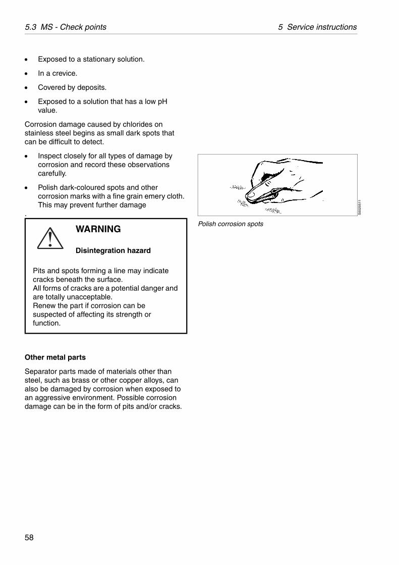
Inspect closely for all types of damage by corrosion and record these observations carefully.
Polish dark-coloured spots and other corrosion marks with a fine grain emery cloth. This may prevent further damage
.
Other metal parts
Separator parts made of materials other than steel, such as brass or other copper alloys, can also be damaged by corrosion when exposed to an aggressive environment. Possible corrosion damage can be in the form of pits and/or cracks.
WARNING
Disintegration hazard
Pits and spots forming a line may indicate cracks beneath the surface.All forms of cracks are a potential danger and are totally unacceptable.Renew the part if corrosion can be suspected of affecting its strength or function.
58

5 Service instructions 5.3 MS - Check points
G02
0522
1
Maximum depth of damage
G05
8991
1
Erosion check points
5.3.2 Erosion
Erosion can occur when particles suspended in the process liquid slide along or strike against a surface. Erosion can become intensified locally by flows of higher velocity.
Always contact your Alfa Laval representative if the largest depth of any erosion damage exceeds 1.0 mm. Valuable information as to the nature of the damage can be recorded using photographs, plaster impressions or hammered-in lead.
Erosion is characterised by:
Burnished traces in the material.
Dents and pits having a granular and shiny surface.
Surfaces particularly subjected to erosion are:
1. The underside of the distributor in the vicinity of the distribution holes and wings.
2. The internal surface of the bowl body that faces the conical part of the distributor.
Look carefully for any signs of erosion damage. Erosion damage can deepen rapidly and consequently weaken parts by reducing the thickness of the metal.
WARNING
Disintegration hazard
Inspect regularly for erosion damage. Inspect frequently if the process liquid is erosive.
WARNING
Disintegration hazard
Erosion damage can weaken parts by reducing the thickness of the metal.
Renew the part if erosion can be suspected of affecting its strength or function.
59
5.3 MS - Check points 5 Service instructions
5.3.3 Cracks
Cracks can initiate on the machine after a period of operation and propagate with time.
Cracks often initiate in an area exposed to high cyclic material stresses. These are called fatigue cracks.
Cracks can also initiate due to corrosion in an aggressive environment.
Although very unlikely, cracks may also occur due to the low temperature embrittlement of certain materials.
The combination of an aggressive environment and cyclic stresses will speed-up the formation of cracks. Keeping the machine and its parts clean and free from deposits will help to prevent corrosion attacks.
It is particularly important to inspect for cracks in rotating parts.
Always contact your Alfa Laval representative if you suspect that the largest depth of the damage exceeds 1.0 mm. Do not continue to use the separator until it has been inspected and cleared for operation by Alfa Laval.
WARNING
Disintegration hazard
All forms of cracks are potentially dangerous as they reduce the strength and functional ability of components.
Always renew a part if cracks are present.
60
5 Service instructions 5.3 MS - Check points
G05
9272
1G
0592
711
5.3.4 Disc stack pressure
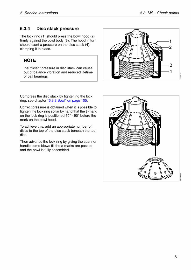
The lock ring (1) should press the bowl hood (2) firmly against the bowl body (3). The hood in turn should exert a pressure on the disc stack (4), clamping it in place.
Compress the disc stack by tightening the lock ring, see chapter ‘‘6.3.3 Bowl” on page 105.
Correct pressure is obtained when it is possible to tighten the lock ring so far by hand that the -mark on the lock ring is positioned 60° - 90° before the mark on the bowl hood.
To achieve this, add an appropriate number of discs to the top of the disc stack beneath the top disc.
Then advance the lock ring by giving the spanner handle some blows till the -marks are passed and the bowl is fully assembled.
NOTE
Insufficient pressure in disc stack can cause out of balance vibration and reduced lifetime of ball bearings.
61
5.3 MS - Check points 5 Service instructions
G05
9241
1G
0592
611
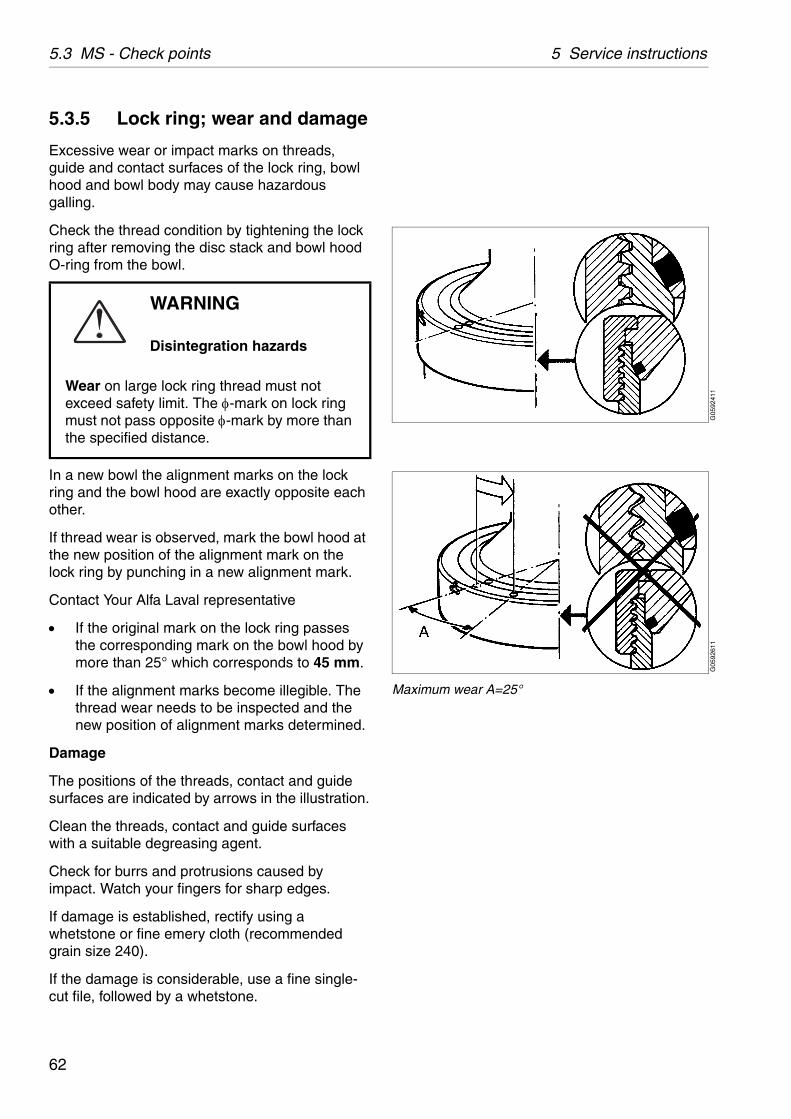
Maximum wear A=25°
5.3.5 Lock ring; wear and damage
Excessive wear or impact marks on threads, guide and contact surfaces of the lock ring, bowl hood and bowl body may cause hazardous galling.
Check the thread condition by tightening the lock ring after removing the disc stack and bowl hood O-ring from the bowl.
In a new bowl the alignment marks on the lock ring and the bowl hood are exactly opposite each other.
If thread wear is observed, mark the bowl hood at the new position of the alignment mark on the lock ring by punching in a new alignment mark.
Contact Your Alfa Laval representative
If the original mark on the lock ring passes the corresponding mark on the bowl hood by more than 25° which corresponds to 45 mm.
If the alignment marks become illegible. The thread wear needs to be inspected and the new position of alignment marks determined.
Damage
The positions of the threads, contact and guide surfaces are indicated by arrows in the illustration.
Clean the threads, contact and guide surfaces with a suitable degreasing agent.
Check for burrs and protrusions caused by impact. Watch your fingers for sharp edges.
If damage is established, rectify using a whetstone or fine emery cloth (recommended grain size 240).
If the damage is considerable, use a fine single-cut file, followed by a whetstone.
WARNING
Disintegration hazards
Wear on large lock ring thread must not exceed safety limit. The -mark on lock ring must not pass opposite -mark by more than the specified distance.
62
5 Service instructions 5.3 MS - Check points
G01
9152
1
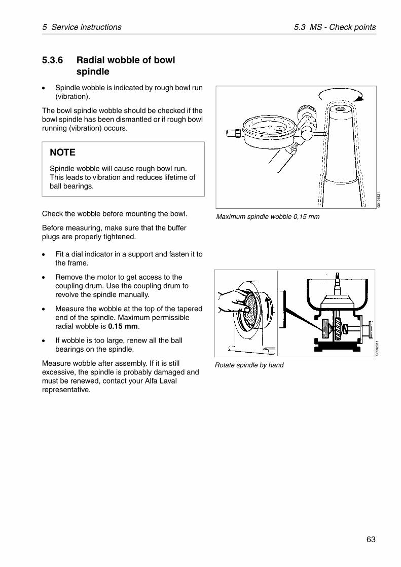
Maximum spindle wobble 0,15 mm
G05
9281
1
Rotate spindle by hand
5.3.6 Radial wobble of bowl spindle
Spindle wobble is indicated by rough bowl run (vibration).
The bowl spindle wobble should be checked if the bowl spindle has been dismantled or if rough bowl running (vibration) occurs.
Check the wobble before mounting the bowl.
Before measuring, make sure that the buffer plugs are properly tightened.
Fit a dial indicator in a support and fasten it to the frame.
Remove the motor to get access to the coupling drum. Use the coupling drum to revolve the spindle manually.
Measure the wobble at the top of the tapered end of the spindle. Maximum permissible radial wobble is 0.15 mm.
If wobble is too large, renew all the ball bearings on the spindle.
Measure wobble after assembly. If it is still excessive, the spindle is probably damaged and must be renewed, contact your Alfa Laval representative.
NOTE
Spindle wobble will cause rough bowl run. This leads to vibration and reduces lifetime of ball bearings.
63
5.3 MS - Check points 5 Service instructions
G05
9931
1G
0607
811
G06
0791
1
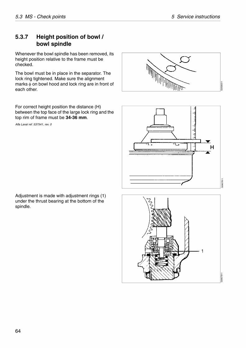
5.3.7 Height position of bowl / bowl spindle
Whenever the bowl spindle has been removed, its height position relative to the frame must be checked.
The bowl must be in place in the separator. The lock ring tightened. Make sure the alignment marks on bowl hood and lock ring are in front of each other.
For correct height position the distance (H) between the top face of the large lock ring and the top rim of frame must be 34-36 mm.Alfa Laval ref. 537541, rev. 0
Adjustment is made with adjustment rings (1) under the thrust bearing at the bottom of the spindle.
64
5 Service instructions 5.3 MS - Check points
G05
9091
1
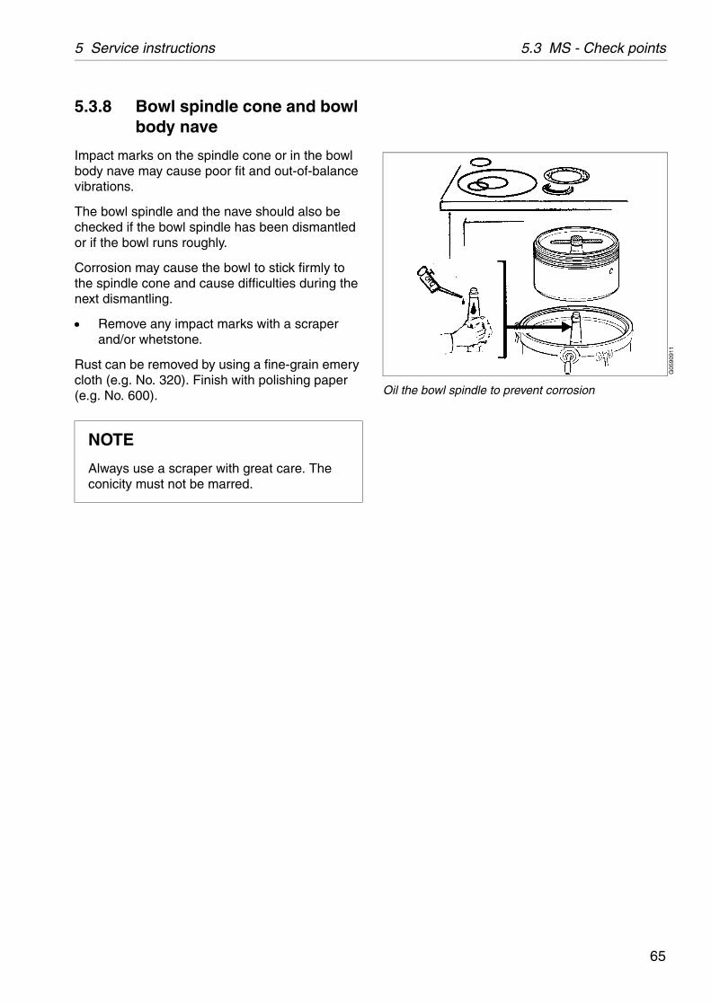
Oil the bowl spindle to prevent corrosion
5.3.8 Bowl spindle cone and bowl body nave
Impact marks on the spindle cone or in the bowl body nave may cause poor fit and out-of-balance vibrations.
The bowl spindle and the nave should also be checked if the bowl spindle has been dismantled or if the bowl runs roughly.
Corrosion may cause the bowl to stick firmly to the spindle cone and cause difficulties during the next dismantling.
Remove any impact marks with a scraper and/or whetstone.
Rust can be removed by using a fine-grain emery cloth (e.g. No. 320). Finish with polishing paper (e.g. No. 600).
NOTE
Always use a scraper with great care. The conicity must not be marred.
65
5.3 MS - Check points 5 Service instructions
G05
9331
1
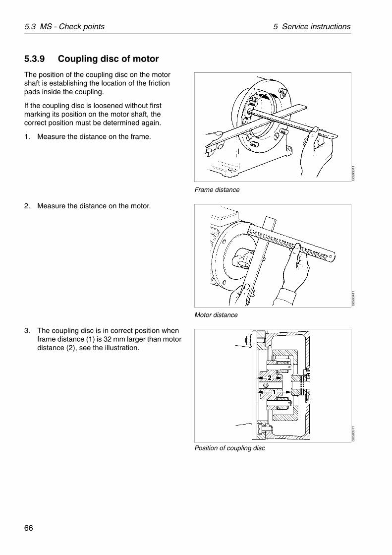
Frame distance
G05
9341
1
Motor distance
G05
9351
1
Position of coupling disc
5.3.9 Coupling disc of motor
The position of the coupling disc on the motor shaft is establishing the location of the friction pads inside the coupling.
If the coupling disc is loosened without first marking its position on the motor shaft, the correct position must be determined again.
1. Measure the distance on the frame.
2. Measure the distance on the motor.
3. The coupling disc is in correct position when frame distance (1) is 32 mm larger than motor distance (2), see the illustration.
66

5 Service instructions 5.3 MS - Check points
G05
9322
1
Friction pads
5.3.10 Friction pads
Worn or oily pads will cause a long running-up period. Renew all the pads even when only one of them is worn.
If the pads are oily:
Clean the pads as well as the inside of the coupling drum with a suitable degreasing agent.
Roughen up the friction surfaces of the pads with a coarse file.
CAUTION
Inhalation hazard
When handling friction blocks/pads use a dust mask to make sure not to inhalate any dust.
Do not use compressed air for removal of any dust. Remove dust by vacuum or wet cloth.
See Safety instructions for environmental issues regarding correct disposal of used friction blocks/pads.
67
5.3 MS - Check points 5 Service instructions
G06
0741
1
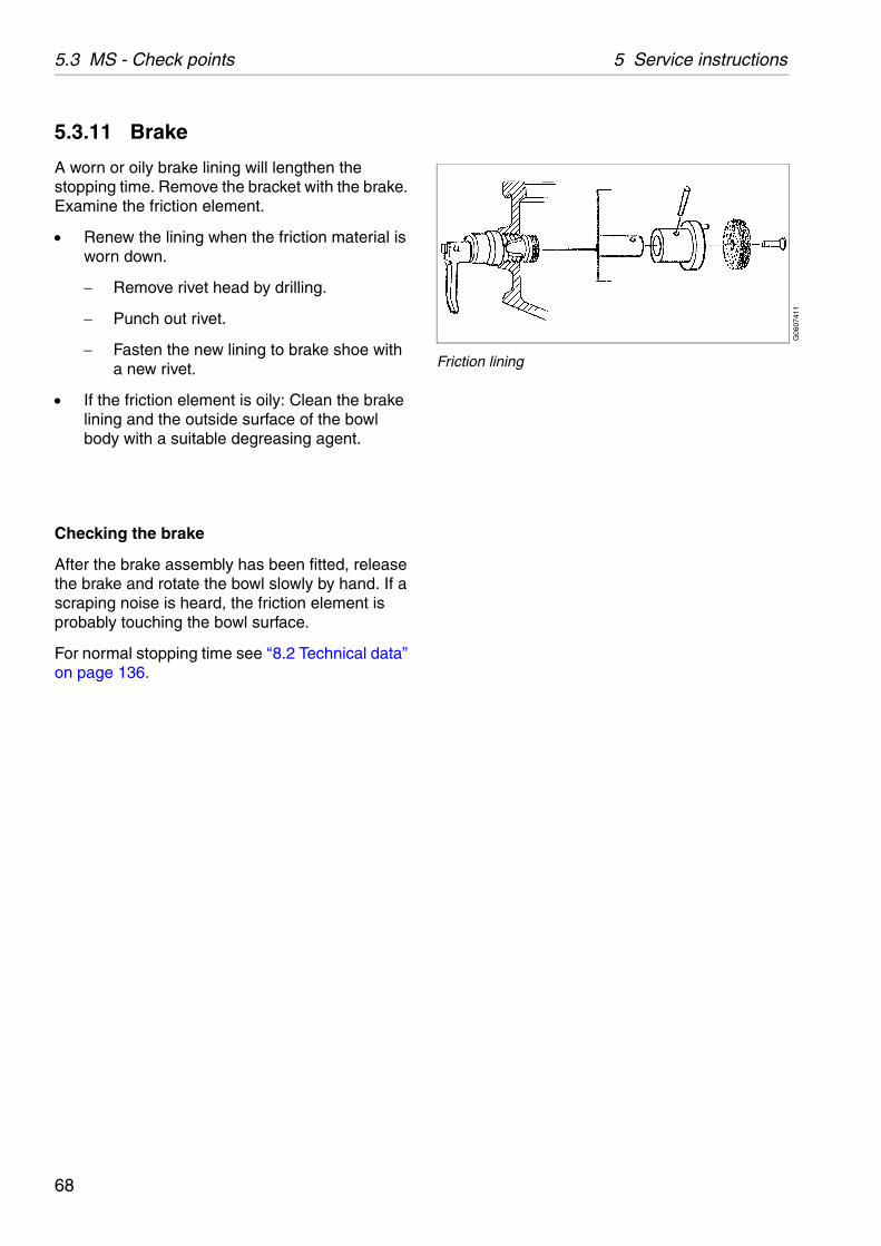
Friction lining
5.3.11 Brake
A worn or oily brake lining will lengthen the stopping time. Remove the bracket with the brake. Examine the friction element.
Renew the lining when the friction material is worn down.
Remove rivet head by drilling.
Punch out rivet.
Fasten the new lining to brake shoe with a new rivet.
If the friction element is oily: Clean the brake lining and the outside surface of the bowl body with a suitable degreasing agent.
Checking the brake
After the brake assembly has been fitted, release the brake and rotate the bowl slowly by hand. If a scraping noise is heard, the friction element is probably touching the bowl surface.
For normal stopping time see ‘‘8.2 Technical data” on page 136.
68
5 Service instructions 5.3 MS - Check points
G06
3501
1
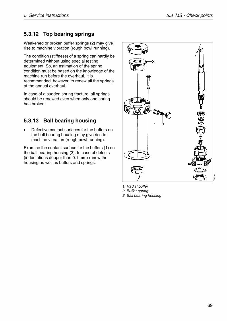
1. Radial buffer2. Buffer spring3. Ball bearing housing
5.3.12 Top bearing springs
Weakened or broken buffer springs (2) may give rise to machine vibration (rough bowl running).
The condition (stiffness) of a spring can hardly be determined without using special testing equipment. So, an estimation of the spring condition must be based on the knowledge of the machine run before the overhaul. It is recommended, however, to renew all the springs at the annual overhaul.
In case of a sudden spring fracture, all springs should be renewed even when only one spring has broken.
5.3.13 Ball bearing housing
Defective contact surfaces for the buffers on the ball bearing housing may give rise to machine vibration (rough bowl running).
Examine the contact surface for the buffers (1) on the ball bearing housing (3). In case of defects (indentations deeper than 0.1 mm) renew the housing as well as buffers and springs.
69

5.3 MS - Check points 5 Service instructions
G05
9292
1
1. Worm wheel2. Worm (part of bowl spindle)
G02
0541
1
5.3.14 Worm wheel and worm; wear of teeth
Check the teeth of worm wheel and worm for wear, see ‘‘ Tooth appearance examples” on page 71.
Examine the contact surfaces and compare the tooth profiles. The gear may operate satisfactorily even when worn to some degree.
When using mineral-type oil in the worm gear housing, the presence of black deposits on the spindle parts is an indication that the oil base has deteriorated seriously or that some of the oil additives have precipitated. If pits are found on the worm gear, the cause could be that the additives are not suitable for this purpose.
In all these cases it is imperative to change to a high-temperature oil. See chapter ‘‘8.9 Lubricants” on page 147.
NOTE
Renew both worm wheel and worm at the same time, even if only one of them is worn.
NOTE
Presence of metal chips in the oil bath is an indication that the gear is wearing abnormally.
70
5 Service instructions 5.3 MS - Check points
G05
3871
1
Satisfactory teeth
G05
3881
1
Worn teeth
G05
3891
1
Spalling
G05
3901
1
Pitting
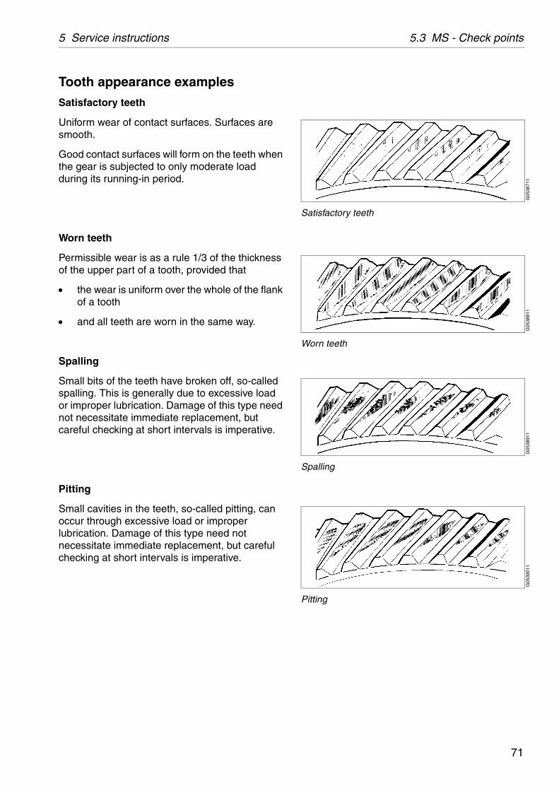
Tooth appearance examples
Satisfactory teeth
Uniform wear of contact surfaces. Surfaces are smooth.
Good contact surfaces will form on the teeth when the gear is subjected to only moderate load during its running-in period.
Worn teeth
Permissible wear is as a rule 1/3 of the thickness of the upper part of a tooth, provided that
the wear is uniform over the whole of the flank of a tooth
and all teeth are worn in the same way.
Spalling
Small bits of the teeth have broken off, so-called spalling. This is generally due to excessive load or improper lubrication. Damage of this type need not necessitate immediate replacement, but careful checking at short intervals is imperative.
Pitting
Small cavities in the teeth, so-called pitting, can occur through excessive load or improper lubrication. Damage of this type need not necessitate immediate replacement, but careful checking at short intervals is imperative.
71
5.4 Cleaning 5 Service instructions
G06
0232
1
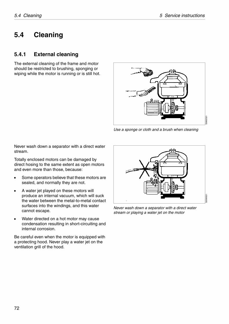
Use a sponge or cloth and a brush when cleaning
G05
9002
1Never wash down a separator with a direct water stream or playing a water jet on the motor
5.4 Cleaning
5.4.1 External cleaning
The external cleaning of the frame and motor should be restricted to brushing, sponging or wiping while the motor is running or is still hot.
Never wash down a separator with a direct water stream.
Totally enclosed motors can be damaged by direct hosing to the same extent as open motors and even more than those, because:
Some operators believe that these motors are sealed, and normally they are not.
A water jet played on these motors will produce an internal vacuum, which will suck the water between the metal-to-metal contact surfaces into the windings, and this water cannot escape.
Water directed on a hot motor may cause condensation resulting in short-circuiting and internal corrosion.
Be careful even when the motor is equipped with a protecting hood. Never play a water jet on the ventilation grill of the hood.
72
5 Service instructions 5.4 Cleaning
S00
0851
1
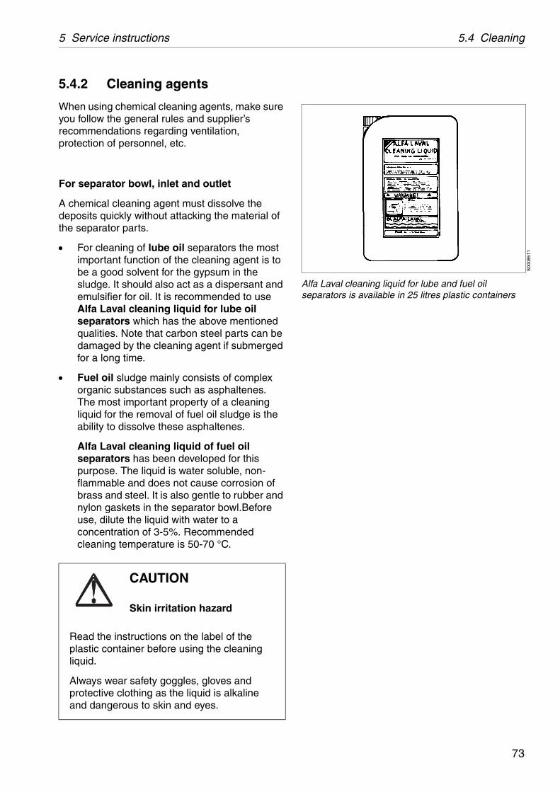
Alfa Laval cleaning liquid for lube and fuel oil separators is available in 25 litres plastic containers
5.4.2 Cleaning agents
When using chemical cleaning agents, make sure you follow the general rules and supplier’s recommendations regarding ventilation, protection of personnel, etc.
For separator bowl, inlet and outlet
A chemical cleaning agent must dissolve the deposits quickly without attacking the material of the separator parts.
For cleaning of lube oil separators the most important function of the cleaning agent is to be a good solvent for the gypsum in the sludge. It should also act as a dispersant and emulsifier for oil. It is recommended to use Alfa Laval cleaning liquid for lube oil separators which has the above mentioned qualities. Note that carbon steel parts can be damaged by the cleaning agent if submerged for a long time.
Fuel oil sludge mainly consists of complex organic substances such as asphaltenes. The most important property of a cleaning liquid for the removal of fuel oil sludge is the ability to dissolve these asphaltenes.
Alfa Laval cleaning liquid of fuel oil separators has been developed for this purpose. The liquid is water soluble, non-flammable and does not cause corrosion of brass and steel. It is also gentle to rubber and nylon gaskets in the separator bowl.Before use, dilute the liquid with water to a concentration of 3-5%. Recommended cleaning temperature is 50-70 °C.
CAUTION
Skin irritation hazard
Read the instructions on the label of the plastic container before using the cleaning liquid.
Always wear safety goggles, gloves and protective clothing as the liquid is alkaline and dangerous to skin and eyes.
73
5.4 Cleaning 5 Service instructions
G05
9292
1
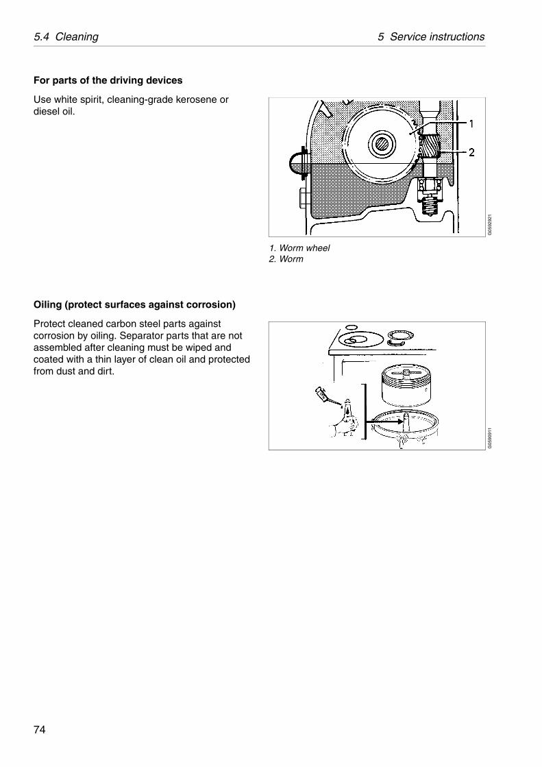
1. Worm wheel2. Worm
G05
9091
1
For parts of the driving devices
Use white spirit, cleaning-grade kerosene or diesel oil.
Oiling (protect surfaces against corrosion)
Protect cleaned carbon steel parts against corrosion by oiling. Separator parts that are not assembled after cleaning must be wiped and coated with a thin layer of clean oil and protected from dust and dirt.
74
5 Service instructions 5.4 Cleaning
G00
6583
1
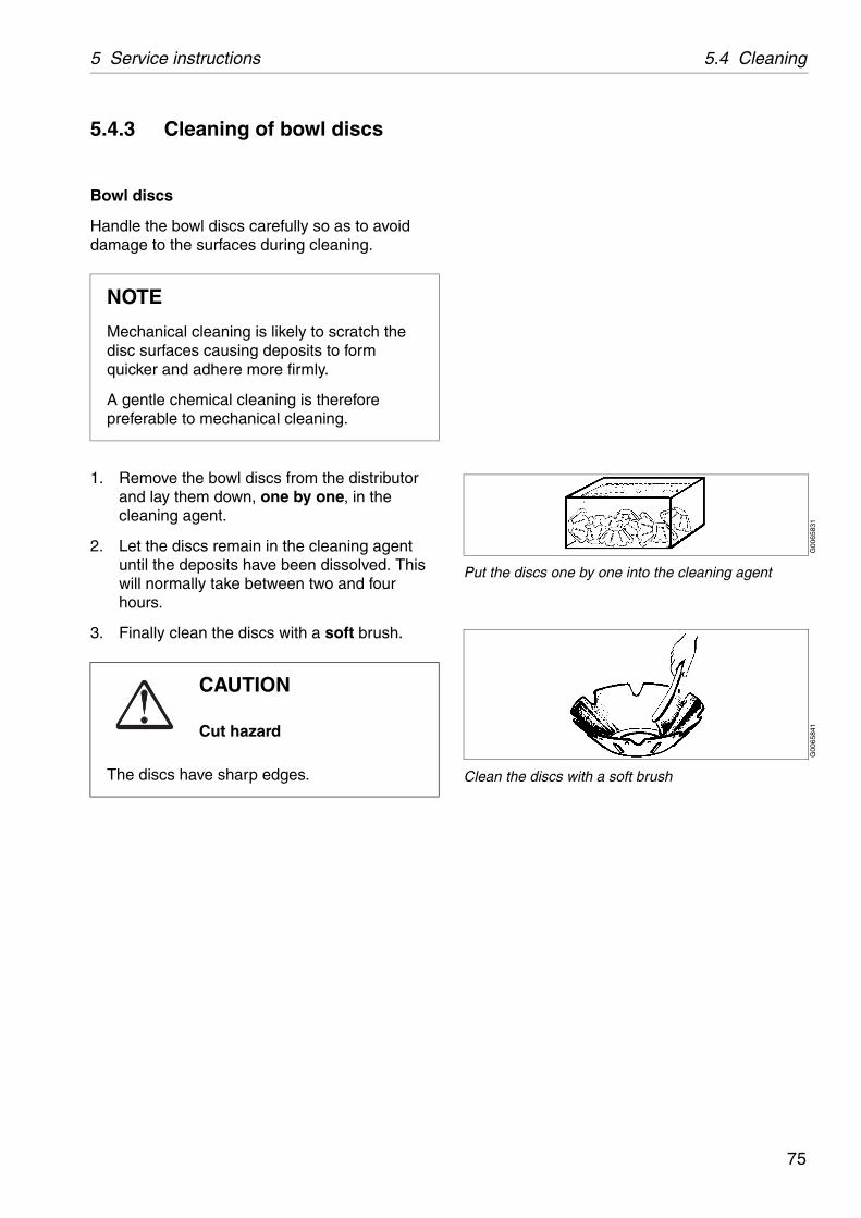
Put the discs one by one into the cleaning agent
G00
6584
1
Clean the discs with a soft brush
5.4.3 Cleaning of bowl discs
Bowl discs
Handle the bowl discs carefully so as to avoid damage to the surfaces during cleaning.
1. Remove the bowl discs from the distributor and lay them down, one by one, in the cleaning agent.
2. Let the discs remain in the cleaning agent until the deposits have been dissolved. This will normally take between two and four hours.
3. Finally clean the discs with a soft brush.
NOTE
Mechanical cleaning is likely to scratch the disc surfaces causing deposits to form quicker and adhere more firmly.
A gentle chemical cleaning is therefore preferable to mechanical cleaning.
CAUTION
Cut hazard
The discs have sharp edges.
75
5.5 When changing oil 5 Service instructions
G06
0262
1G
0602
711
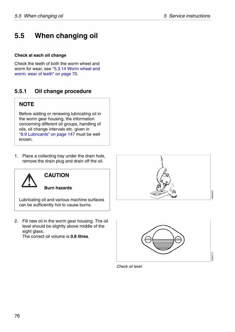
Check oil level
5.5 When changing oil
Check at each oil change
Check the teeth of both the worm wheel and worm for wear, see ‘‘5.3.14 Worm wheel and worm; wear of teeth” on page 70.
5.5.1 Oil change procedure
1. Place a collecting tray under the drain hole, remove the drain plug and drain off the oil.
2. Fill new oil in the worm gear housing. The oil level should be slightly above middle of the sight glass.The correct oil volume is 0.8 litres.
NOTE
Before adding or renewing lubricating oil in the worm gear housing, the information concerning different oil groups, handling of oils, oil change intervals etc. given in‘‘8.9 Lubricants” on page 147 must be well known.
CAUTION
Burn hazards
Lubricating oil and various machine surfaces can be sufficiently hot to cause burns.
76
5 Service instructions 5.6 Common maintenance directions
S00
5561
1
5.6 Common maintenance directions
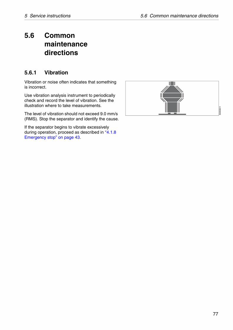
5.6.1 Vibration
Vibration or noise often indicates that something is incorrect.
Use vibration analysis instrument to periodically check and record the level of vibration. See the illustration where to take measurements.
The level of vibration should not exceed 9.0 mm/s (RMS). Stop the separator and identify the cause.
If the separator begins to vibrate excessively during operation, proceed as described in ‘‘4.1.8 Emergency stop” on page 43.
77
5.6 Common maintenance directions 5 Service instructions
G05
8732
1
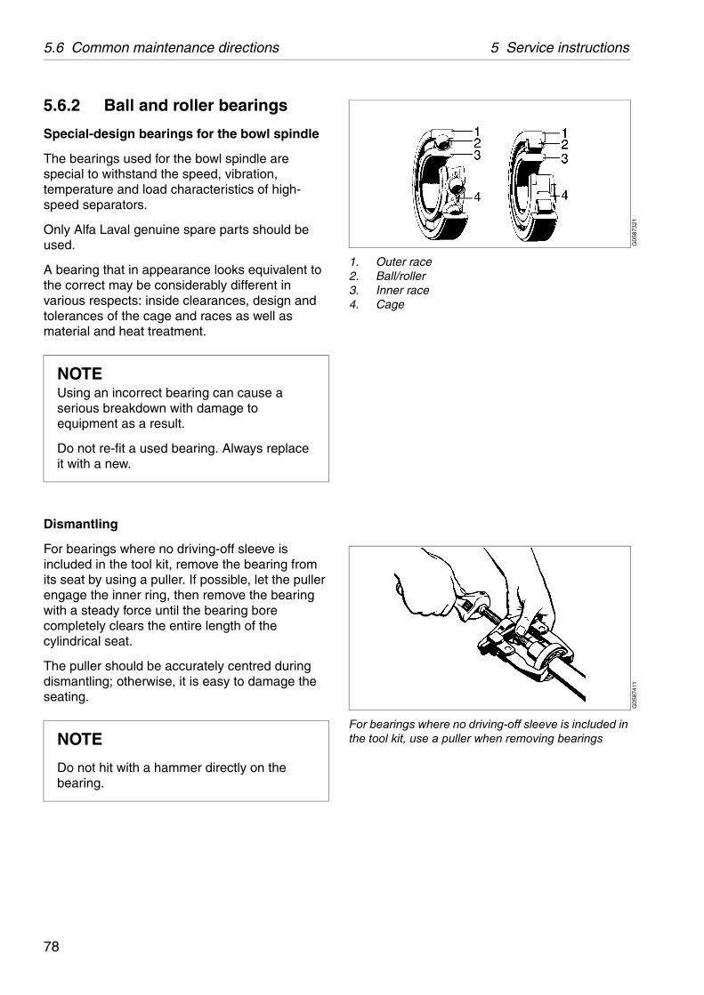
1. Outer race2. Ball/roller3. Inner race4. Cage
G05
8741
1
For bearings where no driving-off sleeve is included in the tool kit, use a puller when removing bearings
5.6.2 Ball and roller bearings
Special-design bearings for the bowl spindle
The bearings used for the bowl spindle are special to withstand the speed, vibration, temperature and load characteristics of high-speed separators.
Only Alfa Laval genuine spare parts should be used.
A bearing that in appearance looks equivalent to the correct may be considerably different in various respects: inside clearances, design and tolerances of the cage and races as well as material and heat treatment.
Dismantling
For bearings where no driving-off sleeve is included in the tool kit, remove the bearing from its seat by using a puller. If possible, let the puller engage the inner ring, then remove the bearing with a steady force until the bearing bore completely clears the entire length of the cylindrical seat.
The puller should be accurately centred during dismantling; otherwise, it is easy to damage the seating.
NOTEUsing an incorrect bearing can cause a serious breakdown with damage to equipment as a result.
Do not re-fit a used bearing. Always replace it with a new.
NOTE
Do not hit with a hammer directly on the bearing.
78
5 Service instructions 5.6 Common maintenance directions
G0
5875
11
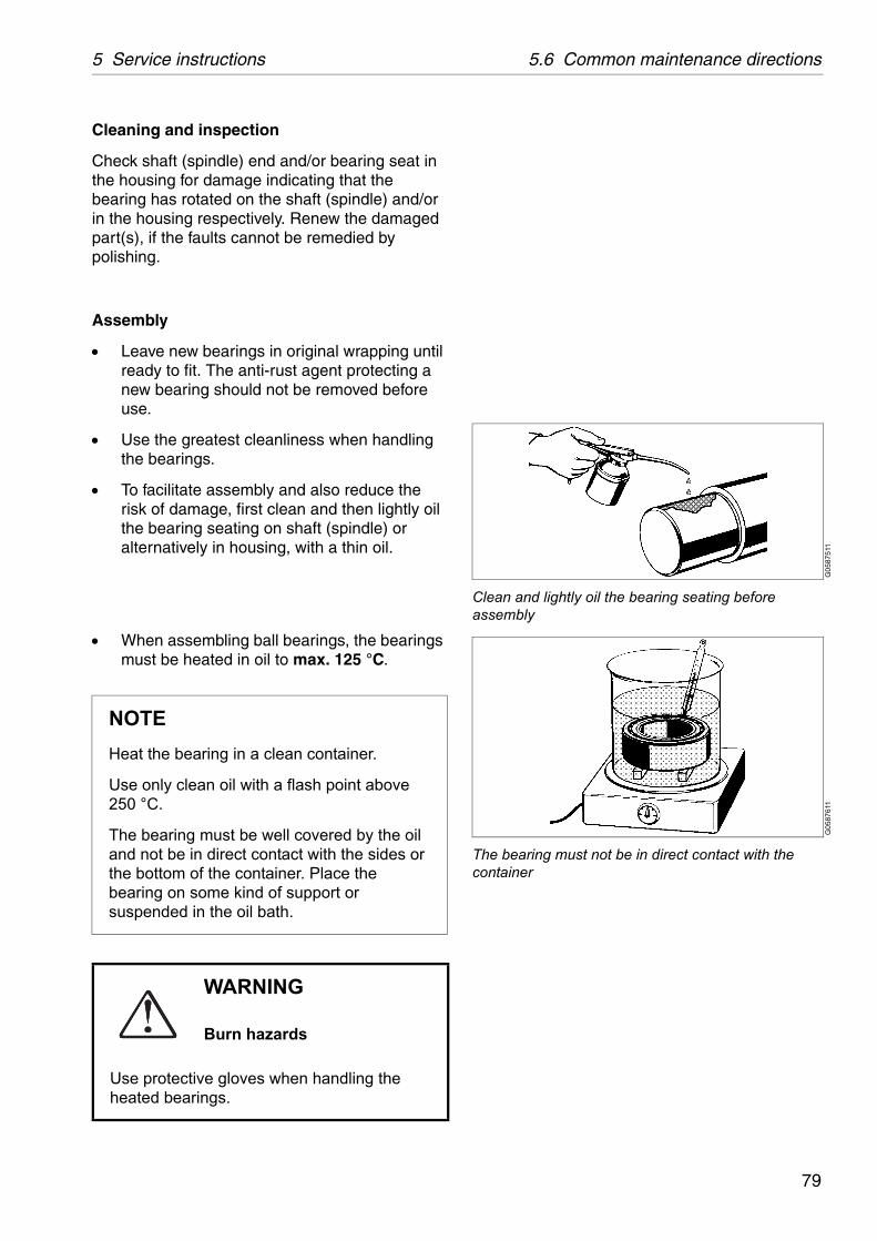
Clean and lightly oil the bearing seating before assembly
G05
8761
1
The bearing must not be in direct contact with the container
Cleaning and inspection
Check shaft (spindle) end and/or bearing seat in the housing for damage indicating that the bearing has rotated on the shaft (spindle) and/or in the housing respectively. Renew the damaged part(s), if the faults cannot be remedied by polishing.
Assembly
Leave new bearings in original wrapping until ready to fit. The anti-rust agent protecting a new bearing should not be removed before use.
Use the greatest cleanliness when handling the bearings.
To facilitate assembly and also reduce the risk of damage, first clean and then lightly oil the bearing seating on shaft (spindle) or alternatively in housing, with a thin oil.
When assembling ball bearings, the bearings must be heated in oil to max. 125 °C.
NOTE
Heat the bearing in a clean container.
Use only clean oil with a flash point above 250 °C.
The bearing must be well covered by the oil and not be in direct contact with the sides or the bottom of the container. Place the bearing on some kind of support or suspended in the oil bath.
WARNING
Burn hazards
Use protective gloves when handling the heated bearings.
79

5.6 Common maintenance directions 5 Service instructions
G05
8771
1
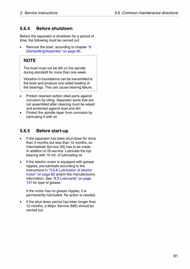
Use a driving-on sleeve for bearings that are not heated
G05
9321
1
A worn coupling increase start-up time
There are several basic rules for assembling cylindrical bore bearings:
Never directly strike a bearing’s rings, cage or rolling elements while assembling. A ring may crack or metal fragments break off.
Never apply pressure to one ring in order to assemble the other.
Use an ordinary hammer. Hammers with soft metal heads are unsuitable as fragments of the metal may break off and enter the bearing.
Make sure the bearing is assembled at a right angle to the shaft (spindle).
If necessary use a driving-on sleeve that abuts the ring which is to be assembled with an interference fit, otherwise there is a risk that the rolling elements and raceways may be damaged and premature failure may follow.
5.6.3 Friction coupling
If the separator does not attain full speed within about 2 minutes, the friction elements or the coupling may be worn or greasy. The friction elements must then be replaced with new ones or thoroughly cleaned from grease.
Before the friction coupling is assembled, examine all parts thoroughly for wear and corrosion.
CAUTION
Inhalation hazard
When handling friction blocks/pads use a dust mask to make sure not to inhalate any dust.
Do not use compressed air for removal of any dust. Remove dust by vacuum or wet cloth.
See Safety instructions for environmental issues regarding correct disposal of used friction blocks/pads.
80
5 Service instructions 5.6 Common maintenance directions
5.6.4 Before shutdown
Before the separator is shutdown for a period of time, the following must be carried out:
Remove the bowl, according to chapter ‘‘6 Dismantling/Assembly” on page 85.
Protect cleaned carbon steel parts against corrosion by oiling. Separator parts that are not assembled after cleaning must be wiped and protected against dust and dirt.
Protect the spindle taper from corrosion by lubricating it with oil.
5.6.5 Before start-up
If the separator has been shut-down for more than 3 months but less than 12 months, an Intermediate Service (IS) has to be made. In addition to IS-service: Lubricate the top bearing with 10 mil. of lubricating oil.
If the electric motor is equipped with grease nipples; pre-lubricate according to the instructions in ‘‘5.6.6 Lubrication of electric motor” on page 82 and/or the manufacturers information. See ‘‘8.9 Lubricants” on page 147 for type of grease.If the motor has no grease nipples, it is permanently lubricated. No action is needed.
If the shut-down period has been longer than 12 months, a Major Service (MS) should be carried out.
NOTE
The bowl must not be left on the spindle during standstill for more than one week.
Vibration in foundations can be transmitted to the bowl and produce one-sided loading of the bearings. This can cause bearing failure.
81
5.6 Common maintenance directions 5 Service instructions
5.6.6 Lubrication of electric motor
For motors equipped without permanently lubricated bearings, correct lubrication interval and recommended type of grease can be found in the manufacturer's instructions.
Manual lubrication
Regreasing while motor is running Remove grease outlet plug or open closing
valve if fitted. Be sure that the lubrication channel is open. Press the specified amount of grease into the
bearing. Let the motor run 1-2 hours to ensure that all
excess grease is forced out of the bearing. Close the grease outlet plug or closing valve if fitted.
Regreasing while motor is at standstill
Regrease motors while running. If this is not possible, lubrication can be carried out while the machine is at a standstill. In this case, use only half the quantity of
grease, then run the motor for a few minutes at full speed.
When the motor has stopped, press the rest of the specified amount of grease into the bearing.
After 1-2 running hours close grease outlet plug or closing valve if fitted.
82
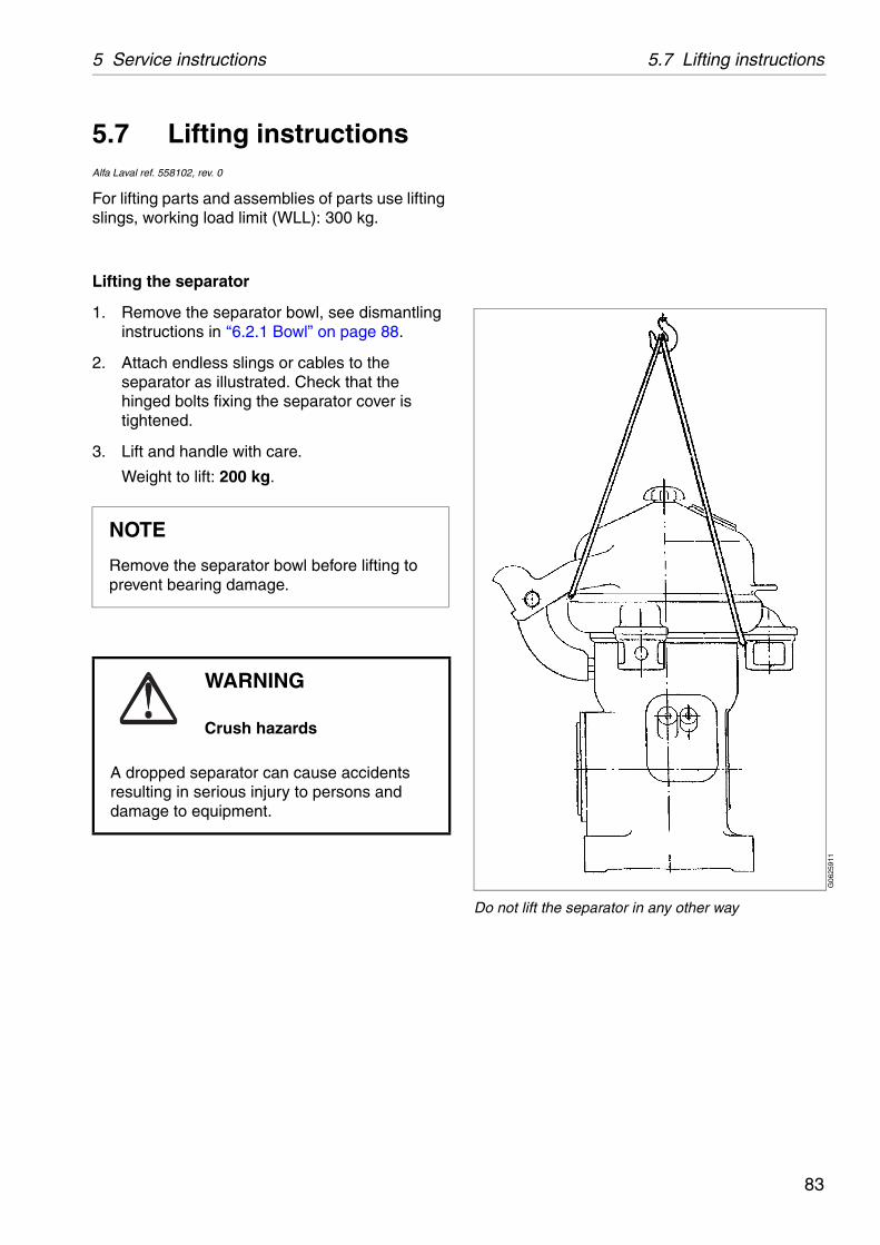
5 Service instructions 5.7 Lifting instructions
G06
2591
1
Do not lift the separator in any other way
5.7 Lifting instructionsAlfa Laval ref. 558102, rev. 0
For lifting parts and assemblies of parts use lifting slings, working load limit (WLL): 300 kg.
Lifting the separator
1. Remove the separator bowl, see dismantling instructions in ‘‘6.2.1 Bowl” on page 88.
2. Attach endless slings or cables to the separator as illustrated. Check that the hinged bolts fixing the separator cover is tightened.
3. Lift and handle with care.
Weight to lift: 200 kg.
NOTE
Remove the separator bowl before lifting to prevent bearing damage.
WARNING
Crush hazards
A dropped separator can cause accidents resulting in serious injury to persons and damage to equipment.
83

5.7 Lifting instructions 5 Service instructions
84
6 Dismantling/Assembly
Contents
6.1 General 86
6.1.1 References to check points 86
6.1.2 Tools 86
6.1.3 Tightening of screws 86
6.2 Dismantling 87
6.2.1 Bowl 88
6.2.2 Vertical driving device 91
6.2.3 Horizontal driving device 94
6.3 Assembly 98
6.3.1 Horizontal driving device 99
6.3.2 Vertical driving device 102
6.3.3 Bowl 105
6.4 Feed and discharge pumps 108
6.4.1 General description 108
6.4.2 Dismantling 110
6.4.3 Assembly 114
6.5 Frame feet 118
6.5.1 Mounting of new frame feet 118
85

6.1 General 6 Dismantling/Assembly
6.1 GeneralThe parts must be handled carefully. Don’t place parts directly on the floor, but on a clean rubber mat, fibreboard or a suitable pallet.
6.1.1 References to check points
In the text you will find references to the check point instructions in Chapter 5. The references appear in the text as in the following example:
✔ Check point‘‘5.3.4 Disc stack pressure” on page 61.
In this example, look up check point ‘‘5.3.4 Disc stack pressure” on page 61 for further instructions.
6.1.2 Tools
Special tools from the tool kit shall be used for dismantling and assembly. The special tools are specified in the Spare Parts Catalogue.
For lifting parts and assemblies of parts use lifting slings, working load limit (WLL): 300 kg.
6.1.3 Tightening of screws
When tightening screws, use the torques stated in the table below unless otherwise stated. The figures apply to lubricated screws tightened with a torque wrench.
METRIC THREAD
Thread
Torques in Nm
Stainless steel
Carbon steel
M6 7 8
M8 17 20
M10 33 39
M12 57 68
M16 140 155
M20 275 325
M24 470 570
86
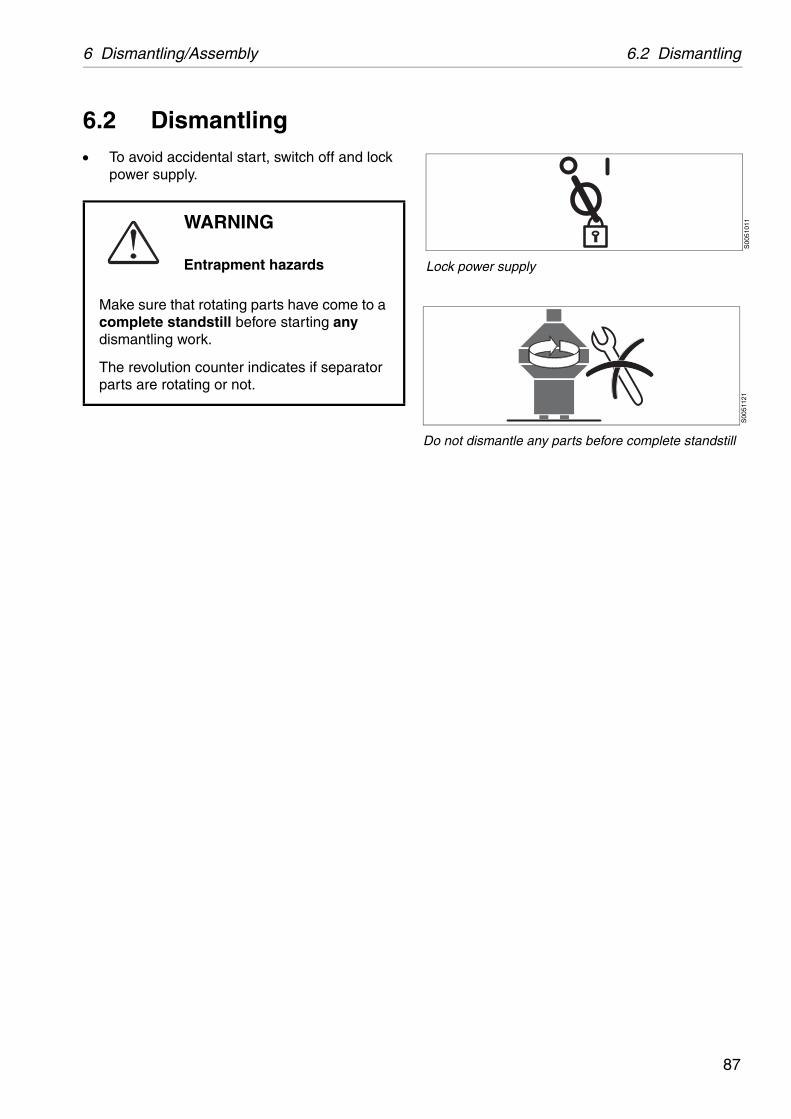
6 Dismantling/Assembly 6.2 Dismantling
S00
5101
1
Lock power supply
S00
5112
1
Do not dismantle any parts before complete standstill
6.2 Dismantling To avoid accidental start, switch off and lock
power supply.
WARNING
Entrapment hazards
Make sure that rotating parts have come to a complete standstill before starting any dismantling work.
The revolution counter indicates if separator parts are rotating or not.
87
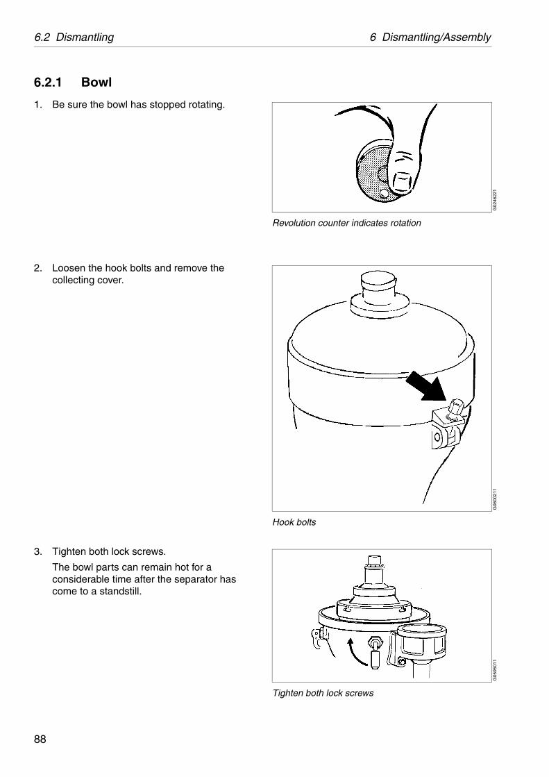
6.2 Dismantling 6 Dismantling/Assembly
G02
4622
1
Revolution counter indicates rotation
G06
0021
1
Hook bolts
G05
9501
1
Tighten both lock screws
6.2.1 Bowl
1. Be sure the bowl has stopped rotating.
2. Loosen the hook bolts and remove the collecting cover.
3. Tighten both lock screws.
The bowl parts can remain hot for a considerable time after the separator has come to a standstill.
88
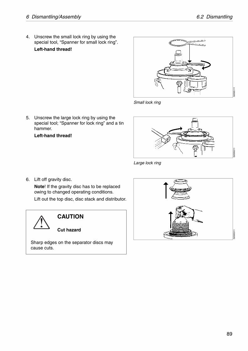
6 Dismantling/Assembly 6.2 Dismantling
G05
9511
1
Small lock ring
G05
9521
1
Large lock ring
G05
9531
1
4. Unscrew the small lock ring by using the special tool, “Spanner for small lock ring”.
Left-hand thread!
5. Unscrew the large lock ring by using the special tool; “Spanner for lock ring” and a tin hammer.
Left-hand thread!
6. Lift off gravity disc.
Note! If the gravity disc has to be replaced owing to changed operating conditions.
Lift out the top disc, disc stack and distributor.
CAUTION
Cut hazard
Sharp edges on the separator discs may cause cuts.
89
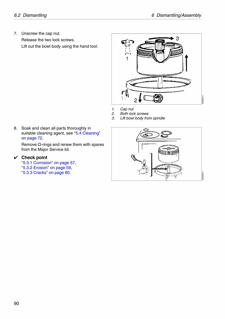
6.2 Dismantling 6 Dismantling/Assembly
G05
9541
1
1. Cap nut2. Both lock screws3. Lift bowl body from spindle
G05
9091
1
7. Unscrew the cap nut.
Release the two lock screws.
Lift out the bowl body using the hand tool.
8. Soak and clean all parts thoroughly in suitable cleaning agent, see ‘‘5.4 Cleaning” on page 72.
Remove O-rings and renew them with spares from the Major Service kit.
✔ Check point‘‘5.3.1 Corrosion” on page 57,‘‘5.3.2 Erosion” on page 59,‘‘5.3.3 Cracks” on page 60.
90

6 Dismantling/Assembly 6.2 Dismantling
G06
0861
1G
0608
711
6.2.2 Vertical driving device
Remove the outlet housings, feed and discharge pumps and raise the collecting cover. Remove also the separator bowl.
Before dismantling, in the case of 8000 hours service, or if the separator vibrates while running:
✔ Check point‘‘5.3.6 Radial wobble of bowl spindle” on page 63.
1. Drain off the oil
Force out the conical pin of the worm wheel.
2. Push worm wheel aside.
91
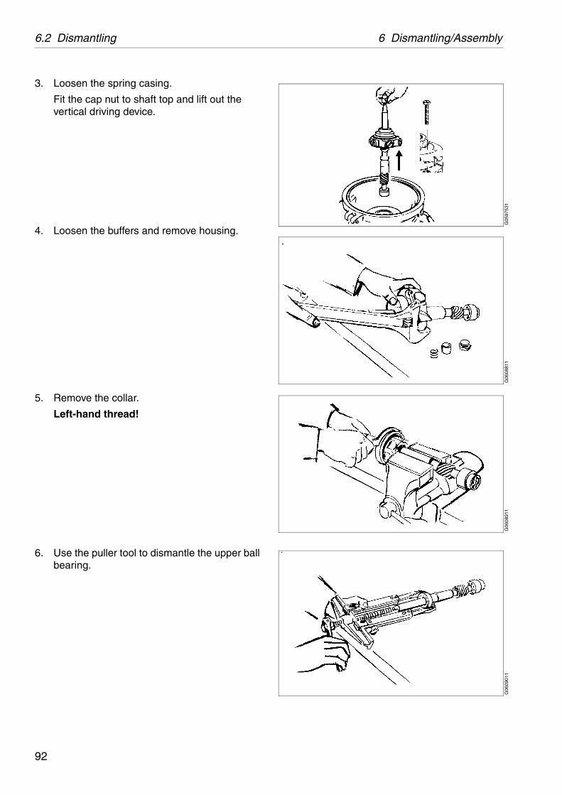
6.2 Dismantling 6 Dismantling/Assembly
G05
9753
1G
0608
811
G06
0891
1G
0609
011
3. Loosen the spring casing.
Fit the cap nut to shaft top and lift out the vertical driving device.
4. Loosen the buffers and remove housing.
5. Remove the collar.
Left-hand thread!
6. Use the puller tool to dismantle the upper ball bearing.
92
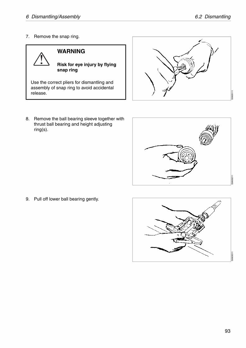
6 Dismantling/Assembly 6.2 Dismantling
G06
0911
1G
0609
211
G06
0931
1
7. Remove the snap ring.
8. Remove the ball bearing sleeve together with thrust ball bearing and height adjusting ring(s).
9. Pull off lower ball bearing gently.
WARNING
Risk for eye injury by flying snap ring
Use the correct pliers for dismantling and assembly of snap ring to avoid accidental release.
93
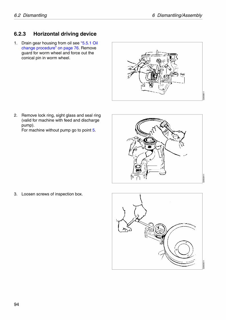
6.2 Dismantling 6 Dismantling/Assembly
G06
0861
1G
0609
411
G06
0951
1
6.2.3 Horizontal driving device
1. Drain gear housing from oil see ‘‘5.5.1 Oil change procedure” on page 76. Remove guard for worm wheel and force out the conical pin in worm wheel.
2. Remove lock ring, sight glass and seal ring (valid for machine with feed and discharge pump).For machine without pump go to point 5.
3. Loosen screws of inspection box.
94
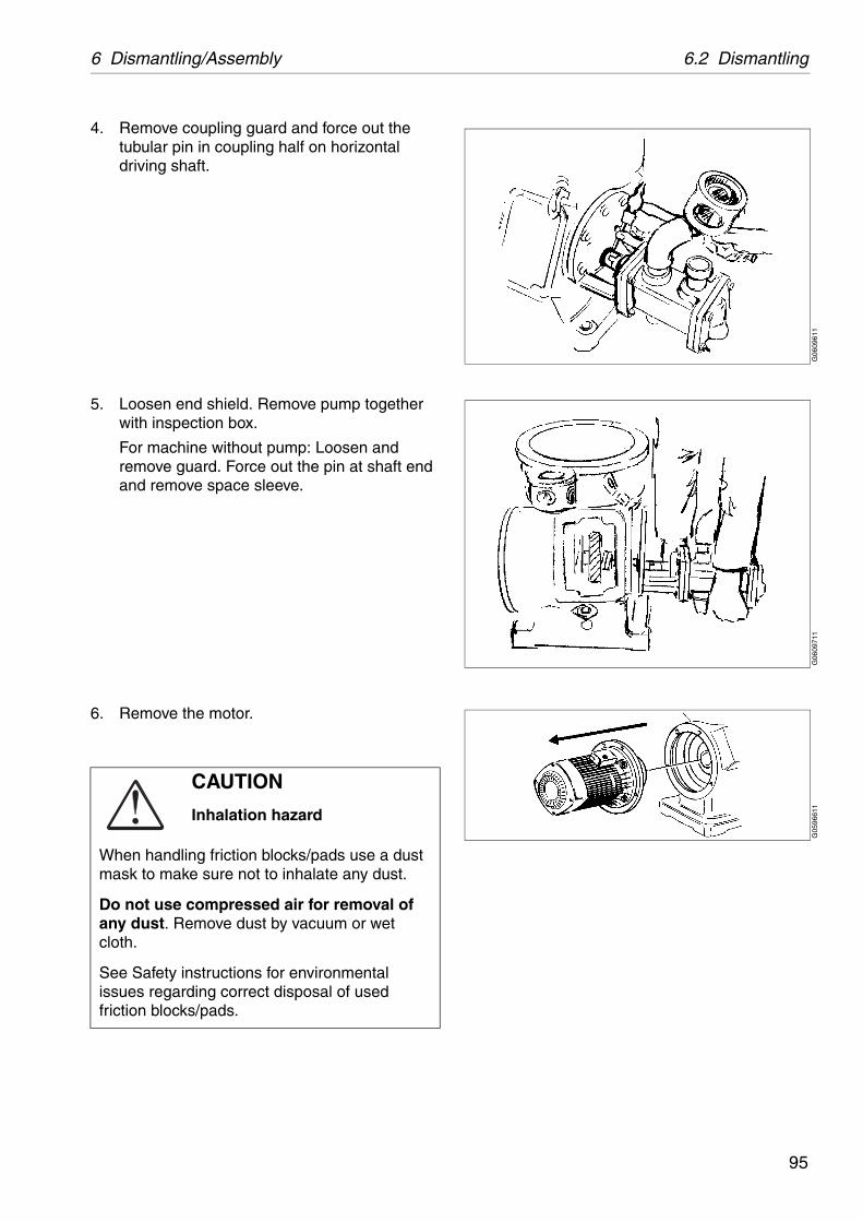
6 Dismantling/Assembly 6.2 Dismantling
G06
0961
1G
0609
711
G05
9661
1
4. Remove coupling guard and force out the tubular pin in coupling half on horizontal driving shaft.
5. Loosen end shield. Remove pump together with inspection box.
For machine without pump: Loosen and remove guard. Force out the pin at shaft end and remove space sleeve.
6. Remove the motor.
CAUTION
Inhalation hazard
When handling friction blocks/pads use a dust mask to make sure not to inhalate any dust.
Do not use compressed air for removal of any dust. Remove dust by vacuum or wet cloth.
See Safety instructions for environmental issues regarding correct disposal of used friction blocks/pads.
95
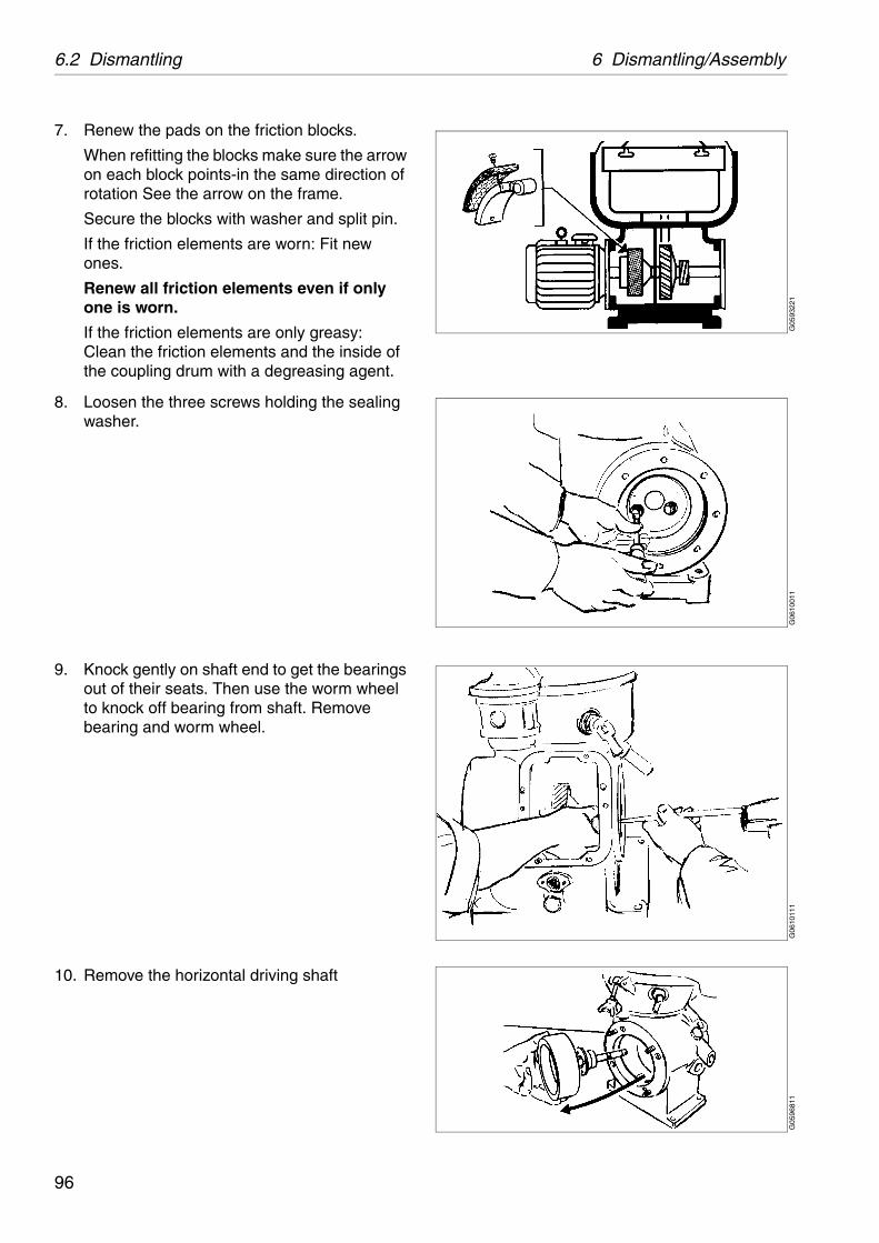
6.2 Dismantling 6 Dismantling/Assembly
G05
9322
1G
0610
011
G06
1011
1G
0596
811
7. Renew the pads on the friction blocks.
When refitting the blocks make sure the arrow on each block points-in the same direction of rotation See the arrow on the frame.
Secure the blocks with washer and split pin.
If the friction elements are worn: Fit new ones.
Renew all friction elements even if only one is worn.
If the friction elements are only greasy:Clean the friction elements and the inside of the coupling drum with a degreasing agent.
8. Loosen the three screws holding the sealing washer.
9. Knock gently on shaft end to get the bearings out of their seats. Then use the worm wheel to knock off bearing from shaft. Remove bearing and worm wheel.
10. Remove the horizontal driving shaft
96

6 Dismantling/Assembly 6.2 Dismantling
G05
9691
1
11. Use the puller tool to pull off the protecting cover and ball bearing. Protect end of worm wheel shaft with a washer.
97

6.3 Assembly 6 Dismantling/Assembly
6.3 AssemblyClean all parts in a degreasing agent and renew parts supplied in the Spare parts kits.
✔ Check point‘‘5.3.1 Corrosion” on page 57,‘‘5.3.2 Erosion” on page 59,‘‘5.3.3 Cracks” on page 60,‘‘5.3.12 Top bearing springs” on page 69,‘‘5.3.13 Ball bearing housing” on page 69,‘‘5.3.14 Worm wheel and worm; wear of teeth” on page 70.
98

6 Dismantling/Assembly 6.3 Assembly
G06
3811
1G
0610
211
6.3.1 Horizontal driving device
1. Fit protection cover on worm wheel shaft. Heat bearing in oil before mounting onto shaft.
2. Clean the ball bearing housing in the frame and oil the outer race of the ball bearing.
Fit the gasket and enter the shaft through the bearing seat in the frame.
99
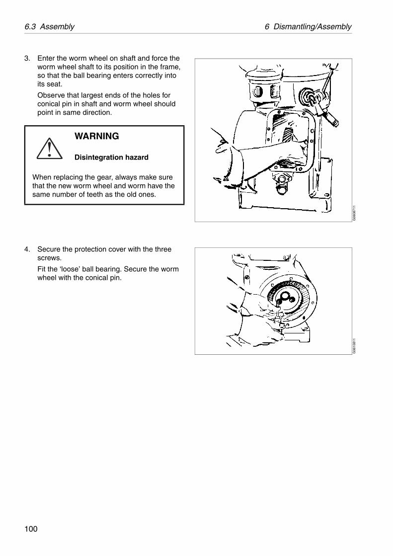
6.3 Assembly 6 Dismantling/Assembly
G06
0871
1G
0610
811
3. Enter the worm wheel on shaft and force the worm wheel shaft to its position in the frame, so that the ball bearing enters correctly into its seat.
Observe that largest ends of the holes for conical pin in shaft and worm wheel should point in same direction.
4. Secure the protection cover with the three screws.
Fit the ‘loose’ ball bearing. Secure the worm wheel with the conical pin.
WARNING
Disintegration hazard
When replacing the gear, always make sure that the new worm wheel and worm have the same number of teeth as the old ones.
100

6 Dismantling/Assembly 6.3 Assembly
G06
0991
1G
0611
011
5. Lift the motor in position and tighten the motor bolts.
If the coupling disc has been loosened without first marking its position on the motor shaft, the correct position for position of coupling disc must be determined again.
✔ Check point‘‘5.3.9 Coupling disc of motor” on page 66.
6. Fit coupling half on worm wheel shaft before mounting the pump.Remember the gasket.
Fit the coupling guard with two screws.
For machine without pump fit distance sleeve and pin at the end of horizontal shaft. Fit and secure the guard.
WARNING
Disintegration hazards
When power cables have been connected, always check direction of rotation. If incorrect, vital rotating parts could unscrew causing disintegration of the machine.
101
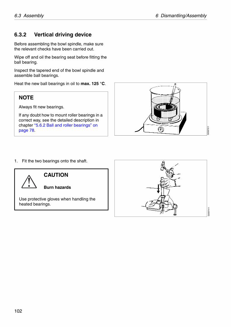
6.3 Assembly 6 Dismantling/Assembly
G05
8761
1G
0597
411
6.3.2 Vertical driving device
Before assembling the bowl spindle, make sure the relevant checks have been carried out.
Wipe off and oil the bearing seat before fitting the ball bearing.
Inspect the tapered end of the bowl spindle and assemble ball bearings.
Heat the new ball bearings in oil to max. 125 °C.
1. Fit the two bearings onto the shaft.
NOTE
Always fit new bearings.
If any doubt how to mount roller bearings in a correct way, see the detailed description in chapter ‘‘5.6.2 Ball and roller bearings” on page 78.
CAUTION
Burn hazards
Use protective gloves when handling the heated bearings.
102
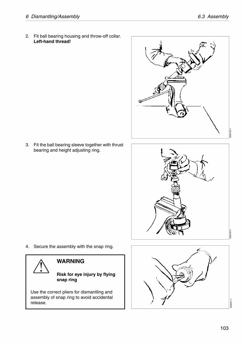
6 Dismantling/Assembly 6.3 Assembly
G06
1041
1G
0610
511
G06
0911
1
2. Fit ball bearing housing and throw-off collar. Left-hand thread!
3. Fit the ball bearing sleeve together with thrust bearing and height adjusting ring.
4. Secure the assembly with the snap ring.
WARNING
Risk for eye injury by flying snap ring
Use the correct pliers for dismantling and assembly of snap ring to avoid accidental release.
103

6.3 Assembly 6 Dismantling/Assembly
G06
0881
1G
0597
511
5. Place spring casing to rest on shoulder of upper ball bearing housing. Fit buffers and springs into casing. Tighten the caps.
6. Place the gasket in the right position at the bottom of the separator frame.
7. Fit the cap nut to the spindle and lower the assembly into the separator frame. Fit the washers and tighten the three screws.
104
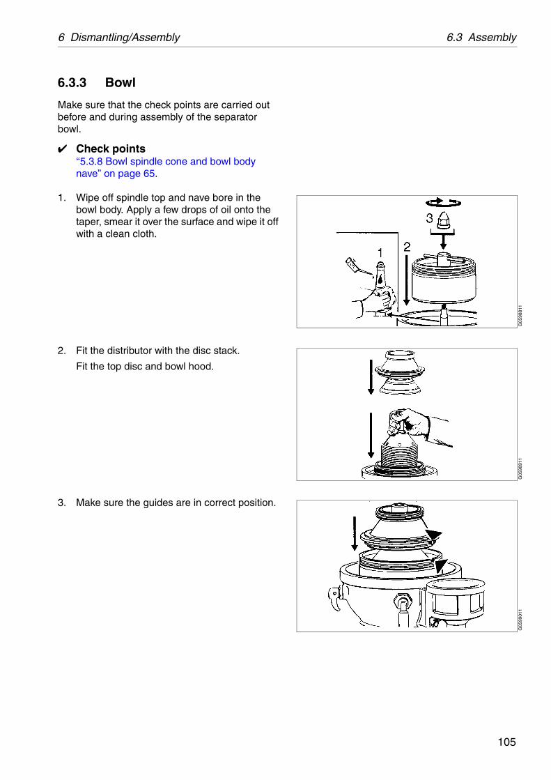
6 Dismantling/Assembly 6.3 Assembly
G05
9881
1G
0598
911
G05
9901
1
6.3.3 Bowl
Make sure that the check points are carried out before and during assembly of the separator bowl.
✔ Check points‘‘5.3.8 Bowl spindle cone and bowl body nave” on page 65.
1. Wipe off spindle top and nave bore in the bowl body. Apply a few drops of oil onto the taper, smear it over the surface and wipe it off with a clean cloth.
2. Fit the distributor with the disc stack.
Fit the top disc and bowl hood.
3. Make sure the guides are in correct position.
105
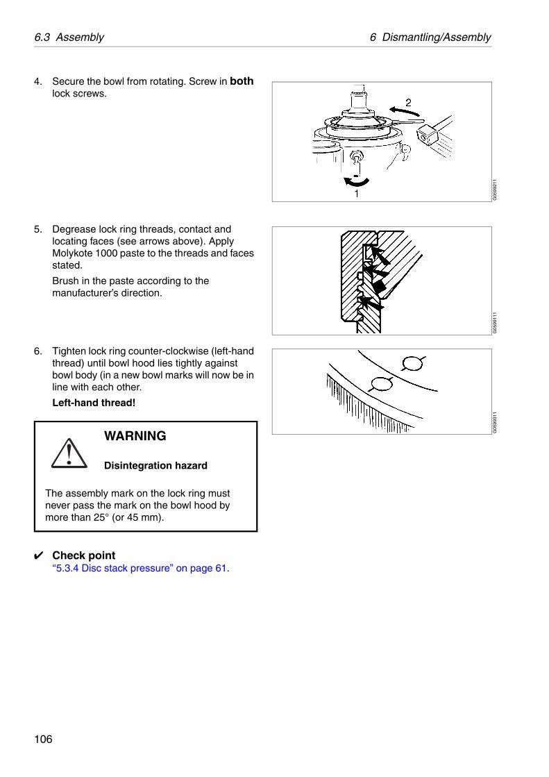
6.3 Assembly 6 Dismantling/Assembly
G05
9921
1G
0599
111
G05
9931
1
4. Secure the bowl from rotating. Screw in both lock screws.
5. Degrease lock ring threads, contact and locating faces (see arrows above). Apply Molykote 1000 paste to the threads and faces stated.
Brush in the paste according to the manufacturer’s direction.
6. Tighten lock ring counter-clockwise (left-hand thread) until bowl hood lies tightly against bowl body (in a new bowl marks will now be in line with each other.
Left-hand thread!
✔ Check point‘‘5.3.4 Disc stack pressure” on page 61.
WARNING
Disintegration hazard
The assembly mark on the lock ring must never pass the mark on the bowl hood by more than 25° (or 45 mm).
106
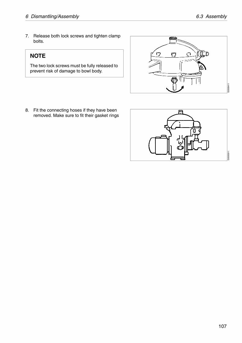
6 Dismantling/Assembly 6.3 Assembly
G05
9941
1G
0593
911
7. Release both lock screws and tighten clamp bolts.
8. Fit the connecting hoses if they have been removed. Make sure to fit their gasket rings
NOTE
The two lock screws must be fully released to prevent risk of damage to bowl body.
107

6.4 Feed and discharge pumps 6 Dismantling/Assembly
G05
9412
1
Double pump
G06
0761
1
1. Bushings2. Wearing seals3. Lipseal rings4. Flexible coupling5. Impeller shaft6. Disengagement7. Axial play
6.4 Feed and discharge pumps
6.4.1 General description
1. Relief/safety valve:
Examine valve cone and valve seat.
2. Bushings:
Renew the bushings if they are scratched or there is a play between shaft and bushing.
3. Wearing seals:
Renew the seals if the surface is rough, crackled or dented by the impeller.
4. Lipseal rings:
Renew the rings at the annual overhaul. Important! Turn the rings the right way round.
5. Flexible coupling:
Check wear on flexible element.
6. Impeller shaft:
Check wear on sealing surface on the impeller shaft.
7. Disengagement:
The feed pump can be disengaged by turning the impeller (6), thereby placing the driving blade of the impeller in the recess of the shield.
108
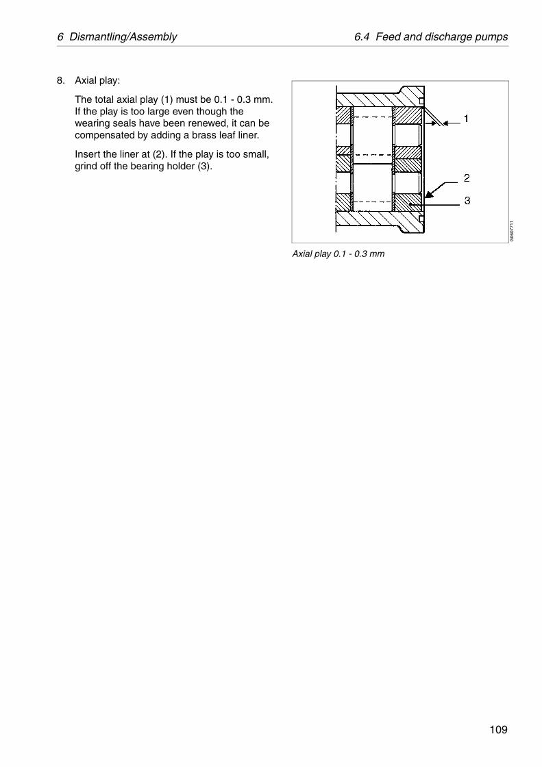
6 Dismantling/Assembly 6.4 Feed and discharge pumps
G06
0771
1
Axial play 0.1 - 0.3 mm
8. Axial play:
The total axial play (1) must be 0.1 - 0.3 mm. If the play is too large even though the wearing seals have been renewed, it can be compensated by adding a brass leaf liner.
Insert the liner at (2). If the play is too small, grind off the bearing holder (3).
109

6.4 Feed and discharge pumps 6 Dismantling/Assembly
G05
9411
1G
0661
411
6.4.2 Dismantling
1. Remove the pipe connections of the pump.
Screw off the lock ring of the sight glass.
Remove the upper gasket and the sight glass.
Remove the screws of the control housing.
Lift the control housing with the lower gasket and the connecting piece.
Unscrew the oil drain plug and empty the gear housing of oil.
2. Remove the guard over the flexible coupling.
110
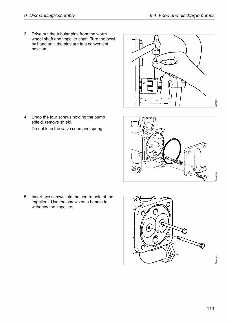
6 Dismantling/Assembly 6.4 Feed and discharge pumps
G06
6131
1G
0661
111
G06
6161
1
3. Drive out the tubular pins from the worm wheel shaft and impeller shaft. Turn the bowl by hand until the pins are in a convenient position.
4. Undo the four screws holding the pump shield, remove shield.
Do not lose the valve cone and spring.
5. Insert two screws into the centre hole of the impellers. Use the screws as a handle to withdraw the impellers.
111
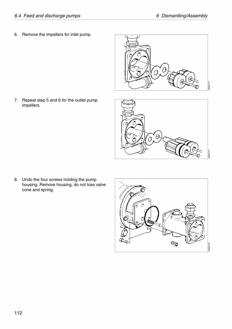
6.4 Feed and discharge pumps 6 Dismantling/Assembly
G06
6171
1G
0661
211
G05
9414
1
6. Remove the impellers for inlet pump.
7. Repeat step 5 and 6 for the outlet pump impellers.
8. Undo the four screws holding the pump housing. Remove housing, do not lose valve cone and spring.
112

6 Dismantling/Assembly 6.4 Feed and discharge pumps
G06
6411
1
9. Check that the lipseal rings are in good condition.If the seal rings are worn or damaged: Remove the pump shield from the separator frame, knock out the old sealring(s) and replace them.
113

6.4 Feed and discharge pumps 6 Dismantling/Assembly
G05
9452
1G
0666
011
G06
6132
1
6.4.3 Assembly
1. Fit new lipseal rings. Be sure to turn it the right way around, the closed side should point outwards to air. Start with the one at pumpside of the shield.
2. Lift pumpshield in place and secure it with one screw at top of shield, do not tighten it fully. Be careful not to damage the seal ring when entering the worm wheel shaft.
3. Fit and secure the coupling half with the larger pinhole on worm wheel shaft. Put the flexible element in place.
114
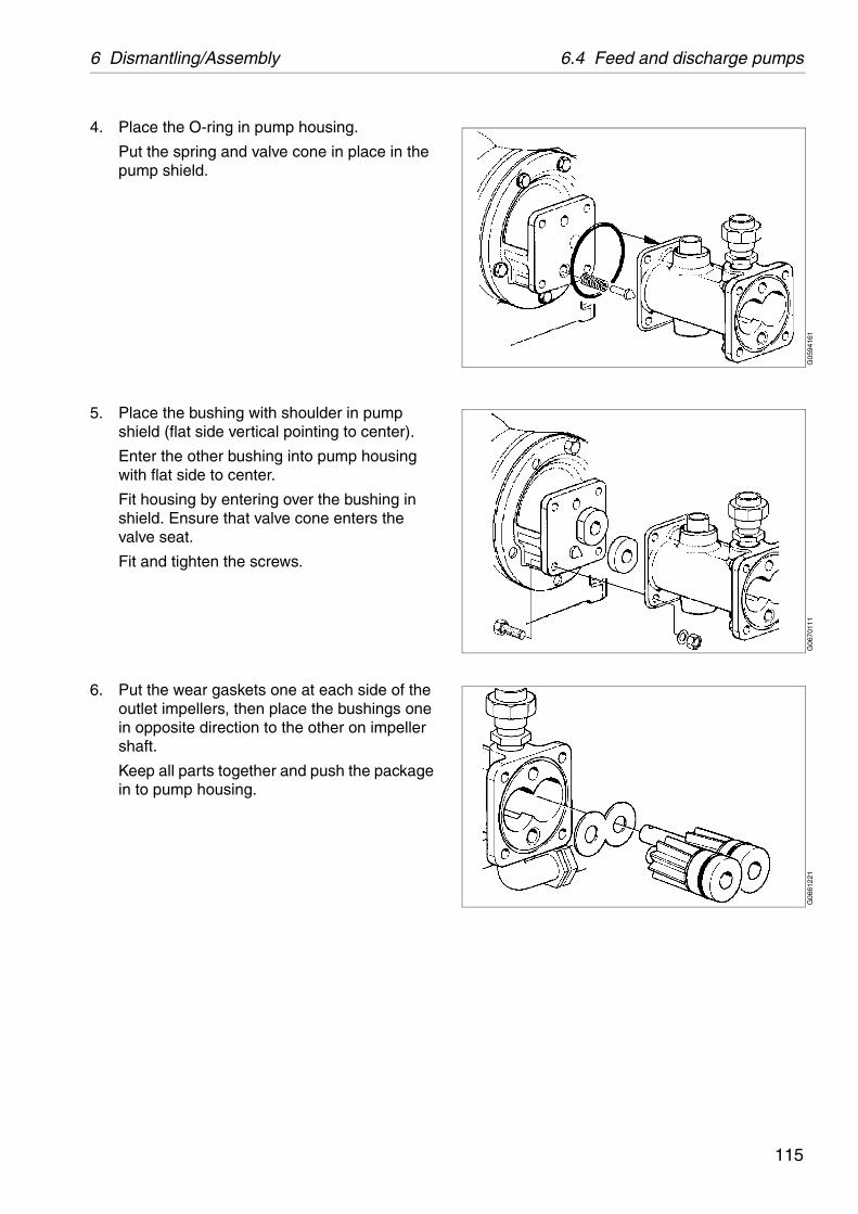
6 Dismantling/Assembly 6.4 Feed and discharge pumps
G05
9416
1G
0670
111
G06
6122
1
4. Place the O-ring in pump housing.
Put the spring and valve cone in place in the pump shield.
5. Place the bushing with shoulder in pump shield (flat side vertical pointing to center).
Enter the other bushing into pump housing with flat side to center.
Fit housing by entering over the bushing in shield. Ensure that valve cone enters the valve seat.
Fit and tighten the screws.
6. Put the wear gaskets one at each side of the outlet impellers, then place the bushings one in opposite direction to the other on impeller shaft.
Keep all parts together and push the package in to pump housing.
115
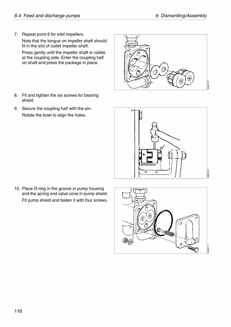
6.4 Feed and discharge pumps 6 Dismantling/Assembly
G06
6172
1G
0661
331
G06
6111
1
7. Repeat point 6 for inlet impellers.
Note that the tongue on impeller shaft should fit in the slot of outlet impeller shaft.
Press gently until the impeller shaft is visible at the coupling side. Enter the coupling half on shaft and press the package in place.
8. Fit and tighten the six screws for bearing shield.
9. Secure the coupling half with the pin.
Rotate the bowl to align the holes.
10. Place O-ring in the groove in pump housing and the spring and valve cone in pump shield.
Fit pump shield and fasten it with four screws.
116

6 Dismantling/Assembly 6.4 Feed and discharge pumps
G06
6141
1G
0594
151
11. Fasten the guard over the flexible coupling.
12. Fit control housing and its pipes.
13. Connect all pipings.
117
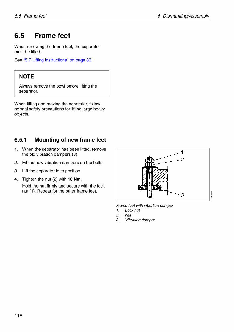
6.5 Frame feet 6 Dismantling/Assembly
G09
2051
1
Frame foot with vibration damper1. Lock nut2. Nut3. Vibration damper
6.5 Frame feetWhen renewing the frame feet, the separator must be lifted.
See ‘‘5.7 Lifting instructions” on page 83.
When lifting and moving the separator, follow normal safety precautions for lifting large heavy objects.
6.5.1 Mounting of new frame feet
1. When the separator has been lifted, remove the old vibration dampers (3).
2. Fit the new vibration dampers on the bolts.
3. Lift the separator in to position.
4. Tighten the nut (2) with 16 Nm.
Hold the nut firmly and secure with the lock nut (1). Repeat for the other frame feet.
NOTE
Always remove the bowl before lifting the separator.
118

7 Trouble-tracing
Contents
7.1 Trouble tracing procedure 121
7.2 Mechanical function 121
7.2.1 The separator does not start 121
7.2.2 Start-up time too long 121
7.2.3 Starting power too low 122
7.2.4 Starting power too high 122
7.2.5 Separator vibrates excessively during starting sequence 123
7.2.6 Separator vibrates excessively during normal running 123
7.2.7 Smell 124
7.2.8 Noise 124
7.2.9 Speed too high 124
7.2.10 Speed too low 125
7.2.11 Stopping time too long 125
7.2.12 Water in oil sump 125
7.2.13 Liquid flows through bowlcasing drain 126
7.3 Purification faults 127
7.3.1 Unsatisfactory separationresult 127
7.3.2 Outgoing water contaminated by oil 127
7.3.3 Broken water seal 128
7.4 Clarification faults 129
7.4.1 Unsatisfactory separation result 129
7.4.2 Oil discharge through water outlet 129
119

7 Trouble-tracing
Study theSystem Manual’sTrouble-tracing
chapter first.(if applicable)
If the problem is not solved in the System Manual’s
Trouble-tracing, continue with this chapter.
Trouble-tracing
120

7 Trouble-tracing 7.1 Trouble tracing procedure
power supply.
e lock screws.
e brake.
friction pads.
.
rrect power supply. See machine plate.
new bearings.
7.1 Trouble tracing procedure
This chapter applies to trouble-tracing concerning functions of the separator only. It does not include the other equipment in your processing system.
Always start with trouble-tracing instructions in the System Manual, and if required, continue with the instructions below. If the problem still is not solved, contact your Alfa Laval representative.
7.2 Mechanical function
7.2.1 The separator does not start
7.2.2 Start-up time too long
Possible cause Action
No power supply to motor. Check
Bowl lock screws stop rotation. Releas
Possible cause Action
Brake applied. Releas
Friction pads worn or oily. Fit new
Motor failure. Repair
Incorrect power supply (50 Hz instead of 60 Hz).
Use co
Bearings damaged or worn. Install
121
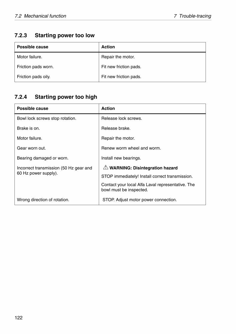
7.2 Mechanical function 7 Trouble-tracing
the motor.
friction pads.
friction pads.
e lock screws.
e brake.
the motor.
worm wheel and worm.
new bearings.
RNING: Disintegration hazard
immediately! Install correct transmission.
t your local Alfa Laval representative. The ust be inspected.
Adjust motor power connection.
7.2.3 Starting power too low
7.2.4 Starting power too high
Possible cause Action
Motor failure. Repair
Friction pads worn. Fit new
Friction pads oily. Fit new
Possible cause Action
Bowl lock screws stop rotation. Releas
Brake is on. Releas
Motor failure. Repair
Gear worn out. Renew
Bearing damaged or worn. Install
Incorrect transmission (50 Hz gear and 60 Hz power supply).
WA
STOP
Contacbowl m
Wrong direction of rotation. STOP.
122

7 Trouble-tracing 7.2 Mechanical function
quence when the separator passes through
RNING: Disintegration hazard
immediately! Identify and rectify cause.
vibration dampers.
w bowl spindle.
bearings.
springs.
and clean bowl.
bearings.
frame feet washers every four years.
all springs.
7.2.5 Separator vibrates excessively during starting sequence
7.2.6 Separator vibrates excessively during normal running
NOTE Some vibration is normal during starting seits critical speeds.
Possible cause Action
Bowl out of balance due to:
poor cleaning
incorrect assembly WA
too few discs
insufficiently tightened bowl hood STOP
bowl assembled with parts from other separators.
Vibration dampers in frame feet worn out. Fit new
Bowl spindle bent (max. 0,15 mm). Fit a ne
Top and/or bottom bearing damaged or worn.
Fit new
Top bearing springs defective. Fit new
Possible cause Action
Uneven sludge deposits in sludge space. STOP
Bearings damaged or worn. Fit new
Vibration-damping rubber washers worn out.
Fit new
Spindle top bearing spring(s) broken. Renew
123

7.2 Mechanical function 7 Trouble-tracing
e the brake.
bearings.
and read oil level and add oil.
bearings.
friction pads.
RNING: Disintegration hazard
immediately! Install correct transmission.
t your local Alfa Laval representative. The ust be inspected.
7.2.7 Smell
7.2.8 Noise
7.2.9 Speed too high
Possible cause Action
Normal occurrence during start as the (new) friction blocks slip.
None.
Brake is applied. Releas
Top and/or bottom bearing overheated. Fit new
Possible cause Action
Oil level in oil sump is too low. STOP
Top and/or bottom bearing damaged or worn.
Fit new
Friction pads worn. Fit new
Possible cause Action
Incorrect transmission (50 Hz gear running on 60 Hz power supply).
WA
STOP
Contacbowl m
Frequency of power supply too high. Check.
124
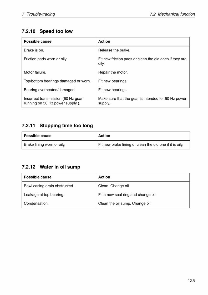
7 Trouble-tracing 7.2 Mechanical function
e the brake.
friction pads or clean the old ones if they are
the motor.
bearings.
bearings.
ure that the gear is intended for 50 Hz power
brake lining or clean the old one if it is oily.
Change oil.
w seal ring and change oil.
the oil sump. Change oil.
7.2.10 Speed too low
7.2.11 Stopping time too long
7.2.12 Water in oil sump
Possible cause Action
Brake is on. Releas
Friction pads worn or oily. Fit newoily.
Motor failure. Repair
Top/bottom bearings damaged or worn. Fit new
Bearing overheated/damaged. Fit new
Incorrect transmission (60 Hz gear running on 50 Hz power supply ).
Make ssupply.
Possible cause Action
Brake lining worn or oily. Fit new
Possible cause Action
Bowl casing drain obstructed. Clean.
Leakage at top bearing. Fit a ne
Condensation. Clean
125

7.2 Mechanical function 7 Trouble-tracing
ed and feed water to create water seal.
e the feed.
ten the hose or clean the strainer. Make sure ter pressure is 200-600 kPa (2-6 bar).
w seal ring.
w seal ring.
ure current is on and brake is off. Inspect nd power transmission.
7.2.13 Liquid flows through bowlcasing drain
Possible cause Action
Broken water seal. Stop fe
Too high throughput Reduc
The supply of displacement/sealing water is not sufficient due to clogged strainer, kinked hose or low water pressure.
Straighthe wa
Seal ring on gravity/clarifier disc defective.
Fit a ne
Bowl hood seal ring defective. Fit a ne
Bowl speed too low. Make smotor a
126
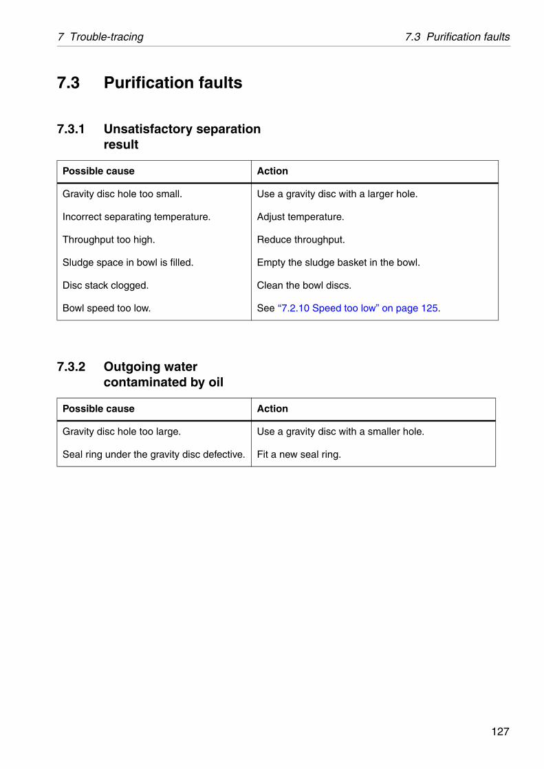
7 Trouble-tracing 7.3 Purification faults
gravity disc with a larger hole.
temperature.
e throughput.
the sludge basket in the bowl.
the bowl discs.
.2.10 Speed too low” on page 125.
gravity disc with a smaller hole.
w seal ring.
7.3 Purification faults
7.3.1 Unsatisfactory separationresult
7.3.2 Outgoing water contaminated by oil
Possible cause Action
Gravity disc hole too small. Use a
Incorrect separating temperature. Adjust
Throughput too high. Reduc
Sludge space in bowl is filled. Empty
Disc stack clogged. Clean
Bowl speed too low. See ‘‘7
Possible cause Action
Gravity disc hole too large. Use a
Seal ring under the gravity disc defective. Fit a ne
127
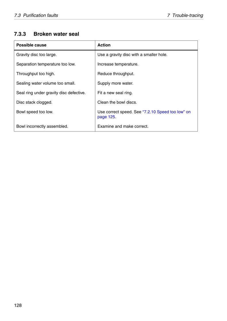
7.3 Purification faults 7 Trouble-tracing
gravity disc with a smaller hole.
e temperature.
e throughput.
more water.
w seal ring.
the bowl discs.
rrect speed. See ‘‘7.2.10 Speed too low” on 25.
e and make correct.
7.3.3 Broken water seal
Possible cause Action
Gravity disc too large. Use a
Separation temperature too low. Increas
Throughput too high. Reduc
Sealing water volume too small. Supply
Seal ring under gravity disc defective. Fit a ne
Disc stack clogged. Clean
Bowl speed too low. Use copage 1
Bowl incorrectly assembled. Examin
128
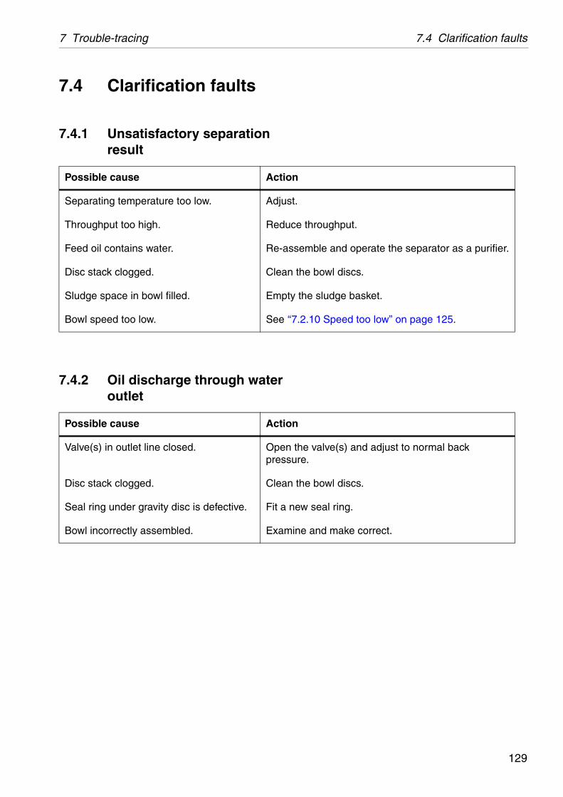
7 Trouble-tracing 7.4 Clarification faults
e throughput.
emble and operate the separator as a purifier.
the bowl discs.
the sludge basket.
.2.10 Speed too low” on page 125.
he valve(s) and adjust to normal back re.
the bowl discs.
w seal ring.
e and make correct.
7.4 Clarification faults
7.4.1 Unsatisfactory separation result
7.4.2 Oil discharge through water outlet
Possible cause Action
Separating temperature too low. Adjust.
Throughput too high. Reduc
Feed oil contains water. Re-ass
Disc stack clogged. Clean
Sludge space in bowl filled. Empty
Bowl speed too low. See ‘‘7
Possible cause Action
Valve(s) in outlet line closed. Open tpressu
Disc stack clogged. Clean
Seal ring under gravity disc is defective. Fit a ne
Bowl incorrectly assembled. Examin
129

7.4 Clarification faults 7 Trouble-tracing
130
8 Technical reference
Contents
8.1 Product description 133
8.1.1 Declaration 134
8.2 Technical data 136
8.2.1 Selection of gravity disc with the nomograph 137
8.3 Basic size drawing, separator without pump 139
8.4 Basic size drawing, separator with pump and no heater 140
8.5 Basic size drawing, separator with pump and heater 141
8.6 Connection list, (with pump and no heater / without pump) 142
8.7 Connection list,(pump and heater) 143
8.8 Interface description 144
8.8.1 Definitions 144
8.8.2 Component description and signal processing 145
8.8.3 Function graph and running limitations 146
8.9 Lubricants 147
8.9.1 Lubrication chart 147
8.9.2 Lubricants 148
8.9.3 Recommended oil brands 152
8.9.4 Recommended oil brands 153
131

8 Technical reference
8.9.5 Recommended oil brands 154
8.9.6 Recommended lubricating oils 156
8.10 Drawings 157
8.10.1 Cross-section, complete separator 157
8.10.2 Cross-section, horizontal driving device 158
8.10.3 Cross-section, purifier bowl 159
8.10.4 Cross-section, clarifier bowl 160
8.10.5 Cross-section, pump 161
8.10.6 Cross-section, water inlet device 163
8.10.7 Machine plates and safety labels 164
8.11 Electric motor 166
8.12 Storage and installation 167
8.12.1 Storage and transport of goods 167
8.12.2 Planning and installation 170
8.12.3 Foundations 173
132
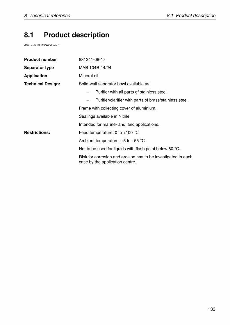
8 Technical reference 8.1 Product description
wl available as:
ll parts of stainless steel.
r with parts of brass/stainless steel.
over of aluminium.
itrile.
d land applications.
+100 °C
+5 to +55 °C
ds with flash point below 60 °C.
erosion has to be investigated in each centre.
8.1 Product descriptionAlfa Laval ref. 9024666, rev. 1
Product number 881241-08-17
Separator type MAB 104B-14/24
Application Mineral oil
Technical Design: Solid-wall separator bo
Purifier with a
Purifier/clarifie
Frame with collecting c
Sealings available in N
Intended for marine- an
Restrictions: Feed temperature: 0 to
Ambient temperature:
Not to be used for liqui
Risk for corrosion and case by the application
133
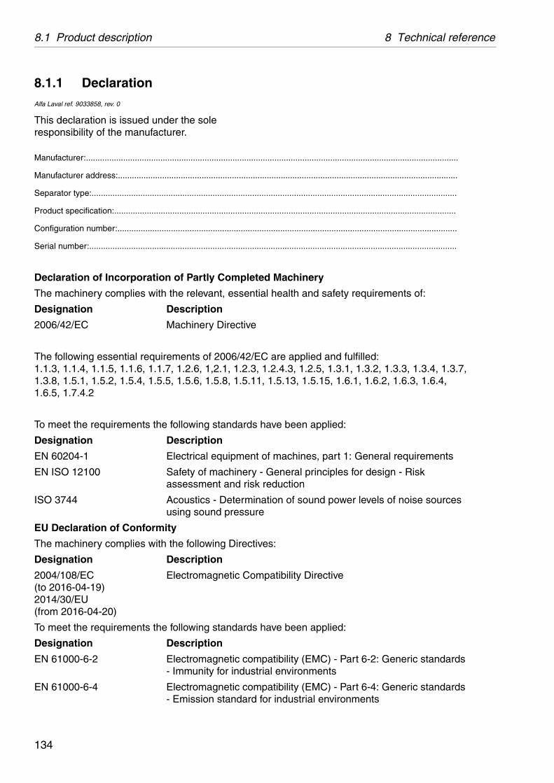
8.1 Product description 8 Technical reference
..................................................................................
.................................................................................
.................................................................................
.................................................................................
.................................................................................
.................................................................................
Machinery
health and safety requirements of:
are applied and fulfilled:.2.4.3, 1.2.5, 1.3.1, 1.3.2, 1.3.3, 1.3.4, 1.3.7,1.5.13, 1.5.15, 1.6.1, 1.6.2, 1.6.3, 1.6.4,
ve been applied:
machines, part 1: General requirements
eneral principles for design - Risk duction
ion of sound power levels of noise sources
s:
atibility Directive
ve been applied:
atibility (EMC) - Part 6-2: Generic standards l environments
atibility (EMC) - Part 6-4: Generic standards r industrial environments
8.1.1 DeclarationAlfa Laval ref. 9033858, rev. 0
This declaration is issued under the sole responsibility of the manufacturer.
Manufacturer:..............................................................................
Manufacturer address:.................................................................
Separator type:............................................................................
Product specification:..................................................................
Configuration number:.................................................................
Serial number:.............................................................................
Declaration of Incorporation of Partly Completed
The machinery complies with the relevant, essential
Designation Description
2006/42/EC Machinery Directive
The following essential requirements of 2006/42/EC1.1.3, 1.1.4, 1.1.5, 1.1.6, 1.1.7, 1.2.6, 1,2.1, 1.2.3, 11.3.8, 1.5.1, 1.5.2, 1.5.4, 1.5.5, 1.5.6, 1.5.8, 1.5.11, 1.6.5, 1.7.4.2
To meet the requirements the following standards ha
Designation Description
EN 60204-1 Electrical equipment of
EN ISO 12100 Safety of machinery - Gassessment and risk re
ISO 3744 Acoustics - Determinatusing sound pressure
EU Declaration of Conformity
The machinery complies with the following Directive
Designation Description
2004/108/EC (to 2016-04-19) 2014/30/EU (from 2016-04-20)
Electromagnetic Comp
To meet the requirements the following standards ha
Designation Description
EN 61000-6-2 Electromagnetic comp- Immunity for industria
EN 61000-6-4 Electromagnetic comp- Emission standard fo
134
8 Technical reference 8.1 Product description
ompiled and retained by the authorized for High Speed Separators, Alfa Laval
pment and must not be put into service until ent, control equipment, auxiliary equipment. ical documentation, and after the completed directives mentioned above, in order to fulfil
..................................................................
..................................................................
..................................................................
..................................................................
..................................................................
..................................................................
The technical construction file for the machinery is cperson Hans Thomasson within the Product Centre Tumba AB, SE-14780 Tumba Sweden.
This machinery is to be incorporated into other equiit has been completed with starting/stopping equipme.g. valves, according to the instructions in the technmachinery has been declared in conformity with thethe EU-requirements.
Signed for and on behalf of: ....................................Place: ....................................
Date of issue: ....................................
Signature: ....................................Name: ....................................
Function: ....................................
135

8.2 Technical data 8 Technical reference
50 rev/min. 50Hz/60Hz
00 rev/min. 50Hz/60Hz
9:12 50Hz/60Hz
m³/h
00 kg/m³
min./max. °C
kg (without motor)
kW (without pump/ with pump)
kg/m² 50Hz
kg/m² 60Hz
kW (idling/at max. capacity)
kW (at starting up)
minutes (min./ max.)
minutes (min./ max.)
minutes (average)
litres
minutesminutes
Bel(A) /dB(A)
mm/sec (new sep./sep. in use)
mm
litres
kg
377-02
ontact with process liquid.
8.2 Technical dataAlfa Laval ref. 558168, rev 2
Bowl speed max. 7500 / 73
Speed motor shaft max. 1500 / 18
Gear ratio 50:10 / 4
Hydraulic capacity 2
Max. density of sediment/feed. 1600 / 11
Feed temperature 0 / 100
Weight of separator 149
Motor power 1,1 / 1,5
Jp reduced to motor shaft 4,8
Jp reduced to motor shaft 3,2
Power consumption 0,5 / 1,8
Max. power consumption 1,3
Starting time 2 / 3
Stopping time with brake 1,4 / 3
Stopping time without brake 9
Lubricating oil volume 0,8
Max. running time:empty bowlfilled bowl, without flow
480480
Sound power/sound press. level 9,3 / 78
Vibration level max. 9
Bowl max. inner diameter 214
Bowl volume 2,5
Bowl weight 25
Bowl body material AL 111 2
There are other materials than stainless steel in c
136

8 Technical reference 8.2 Technical data
gravity disc with large hole as al in the bowl or an
gravity disc with bigger hole based on the density
own and the heavy liquid is st be used from table one (I). able two (II), separating e hole diameter is inscribed
ter
erature between 15°C -70°C e diameter for the disc is ure up to 100°C (121°F) from
II
(60°F) 0, 87 at 25°C (75°F)
60°C (140°F)
83 mm
8.2.1 Selection of gravity disc with the nomograph
The best separating results are obtained by using a possible, one which will not cause a broken water seemulsification in the water outlet.The presence of salt water may demand the use of than indicated in the nomograph (the nomograph is properties of fresh water).
Table for obtaining the gravity disc
If the light-liquid specific weight at 15°C (60°F) is knwater, the obtain diameter with gravity-disc should firIf separating temperature is 55° C (130° C) or from ttemperature is between 80°-100°C (175°-212°F). Thin millimetre (mm) on every disc.
Table I Table II hole diamemm
0,999 - 0,991 1,002 - 0,994 57, 5
0,991 - 0,980 0,994 - 0,982 60
0,980 - 0, 963 0,982 - 0,966 63
0,963 - 0,938 0,966 - 0,942 68
0,938 - 0,901 0,942 - 0,906 73, 5
0,901 - 0,843 0,906 - 0,849 83
0,843 - 0,849 93, 5
Nomograph for obtaining gravity disc
If the light-phase specific weight is known at a temp(60°F - 158°F) and the heavy phase is water, then thobtained by first testing with the separating temperatthe given nomograph.
Example in the nomograph I
Designation in the graph
The light phase specific weight 0, 96 at 15°C
Separating temperature 70°C (160°F)
Hole diameter. 68 mm
137

8.2 Technical data 8 Technical reference
120 130 150 160 170 180- 210 F- 210 F
57,5
60
63
68
73,5
83
93,5
50 60 70 80 - 100 C- 100 C
140
O
O
X
Ø
G06
1195
1
Gravity disc nomograph
X = Separating temperature in °C and °F
Y = The light phase specific weight
ø = Gravity disc hole diameter mm
50 60 70 80 90 100 110
1,00
0,95
0,90
0,85
0,80
0,75
15 20 30 40
Y
IIII
I
II
138
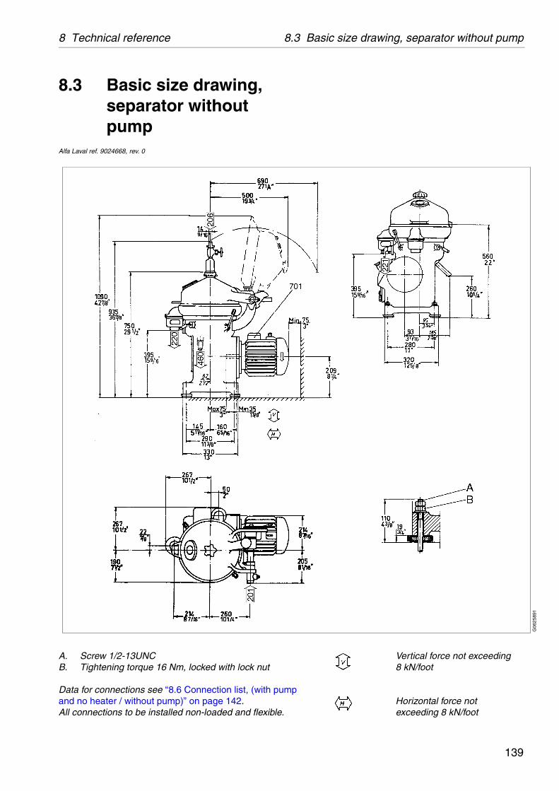
8 Technical reference 8.3 Basic size drawing, separator without pump
Vertical force not exceeding 8 kN/foot
Horizontal force not exceeding 8 kN/foot
G06
2589
1
8.3 Basic size drawing, separator without pump
Alfa Laval ref. 9024668, rev. 0
A. Screw 1/2-13UNCB. Tightening torque 16 Nm, locked with lock nut
Data for connections see ‘‘8.6 Connection list, (with pumpand no heater / without pump)” on page 142.All connections to be installed non-loaded and flexible.
139

8.4 Basic size drawing, separator with pump and no heater 8 Technical reference
Vertical force not exceeding 8 kN/foot
Horizontal force not exceeding 8 kN/foot
G06
2574
1
8.4 Basic size drawing, separator with pump and no heater
Alfa Laval ref. 9024670, rev. 0
A. R 3/4", BSP 3/4B. R 1 1/4", BSP 1 1/4C, D. R 1", BSP 1E. 1/2-13 UNCF. View
Data for connections see ‘‘8.6 Connection list, (with pumpand no heater / without pump)” on page 142.All connections to be installed non-loaded and flexible.
140
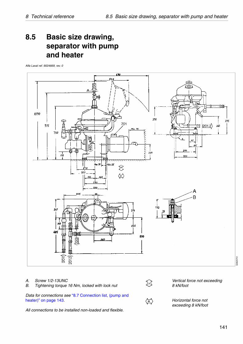
8 Technical reference 8.5 Basic size drawing, separator with pump and heater
Vertical force not exceeding 8 kN/foot
Horizontal force not exceeding 8 kN/foot
G06
2575
1
8.5 Basic size drawing, separator with pump and heater
Alfa Laval ref. 9024669, rev. 0
A. Screw 1/2-13UNCB. Tightening torque 16 Nm, locked with lock nut
Data for connections see ‘‘8.7 Connection list, (pump andheater)” on page 143.
All connections to be installed non-loaded and flexible.
141
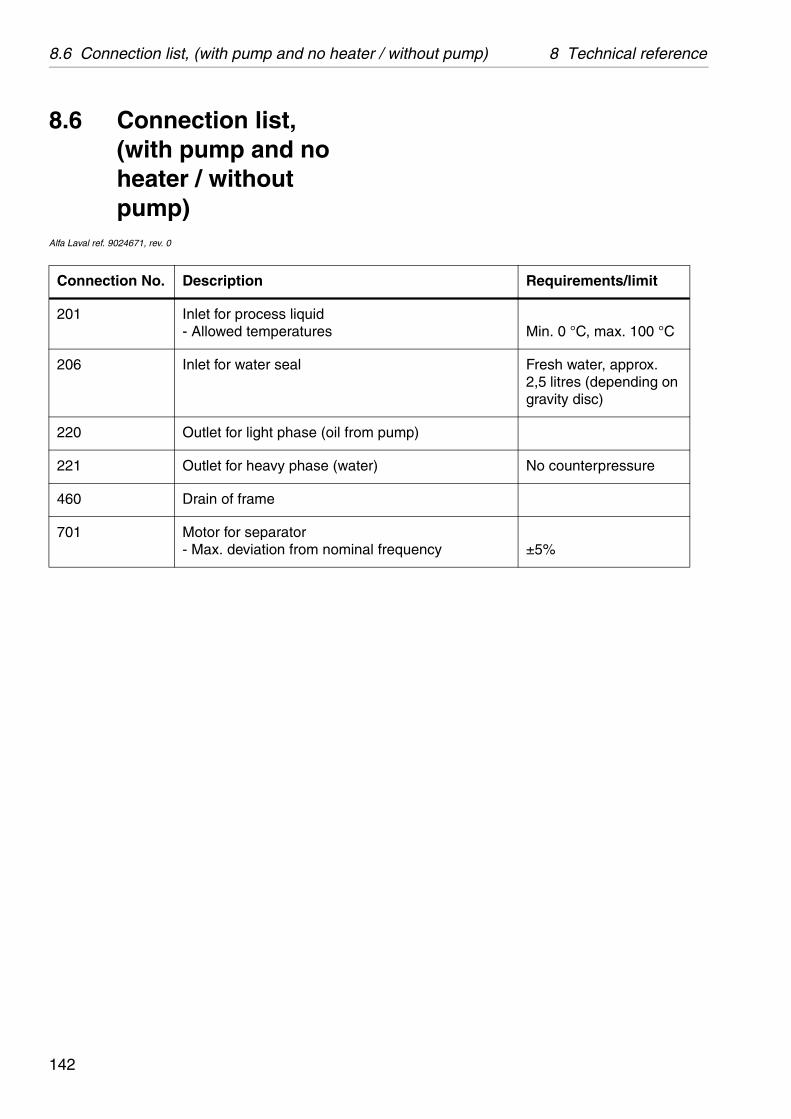
8.6 Connection list, (with pump and no heater / without pump) 8 Technical reference
Requirements/limit
Min. 0 °C, max. 100 °C
Fresh water, approx. 2,5 litres (depending on gravity disc)
ump)
No counterpressure
requency±5%
8.6 Connection list, (with pump and no heater / without pump)
Alfa Laval ref. 9024671, rev. 0
Connection No. Description
201 Inlet for process liquid- Allowed temperatures
206 Inlet for water seal
220 Outlet for light phase (oil from p
221 Outlet for heavy phase (water)
460 Drain of frame
701 Motor for separator- Max. deviation from nominal f
142
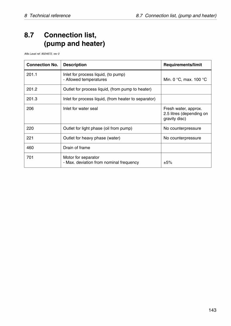
8 Technical reference 8.7 Connection list, (pump and heater)
Requirements/limit
p) Min. 0 °C, max. 100 °C
pump to heater)
ater to separator)
Fresh water, approx. 2.5 litres (depending on gravity disc)
ump) No counterpressure
No counterpressure
requency±5%
8.7 Connection list,(pump and heater)
Alfa Laval ref. 9024672, rev 0
Connection No. Description
201.1 Inlet for process liquid, (to pum- Allowed temperatures
201.2 Outlet for process liquid, (from
201.3 Inlet for process liquid, (from he
206 Inlet for water seal
220 Outlet for light phase (oil from p
221 Outlet for heavy phase (water)
460 Drain of frame
701 Motor for separator- Max. deviation from nominal f
143
8.8 Interface description 8 Technical reference
8.8 Interface descriptionAlfa Laval ref. 9024640, rev 0
In addition to the Connection List this document describes limitations and conditions for safe control, monitoring and reliable operation.
At the end of the document a function graph and running limitations are to be found.
8.8.1 Definitions
Standstill means:
The machine is assembled correctly.
All connections are installed according to Connection List, Interconnection Diagram and Interface Description.
Start means:
The power to the separator is on.
The acceleration is supervised to ensure that a certain speed has been reached within a certain time. See ‘‘8.2 Technical data” on page 136.
Normal stop means:
Stopping of the machine at any time with feed or safety/backup liquid and with brake applied.
144

8 Technical reference 8.8 Interface description
Safety stop means:
The machine must be stopped in the quickest and safest way due to vibrations or process reasons.
Comply with following conditions:
The bowl must be kept filled.
The machine must not be restarted before the reason for the Safety stop has been investigated and action has been taken.
In case of emergency condition in the plant, the machine must be stopped in a way that is described in EN 418.
8.8.2 Component description and signal processing
Electrical connections
Separator motor 701
The separator is equipped with a 3-phase DOL-started (direct on line) motor. The separator can also be started by a Y/D starter, but then the time in Y-position must be maximised to 5 seconds.
145
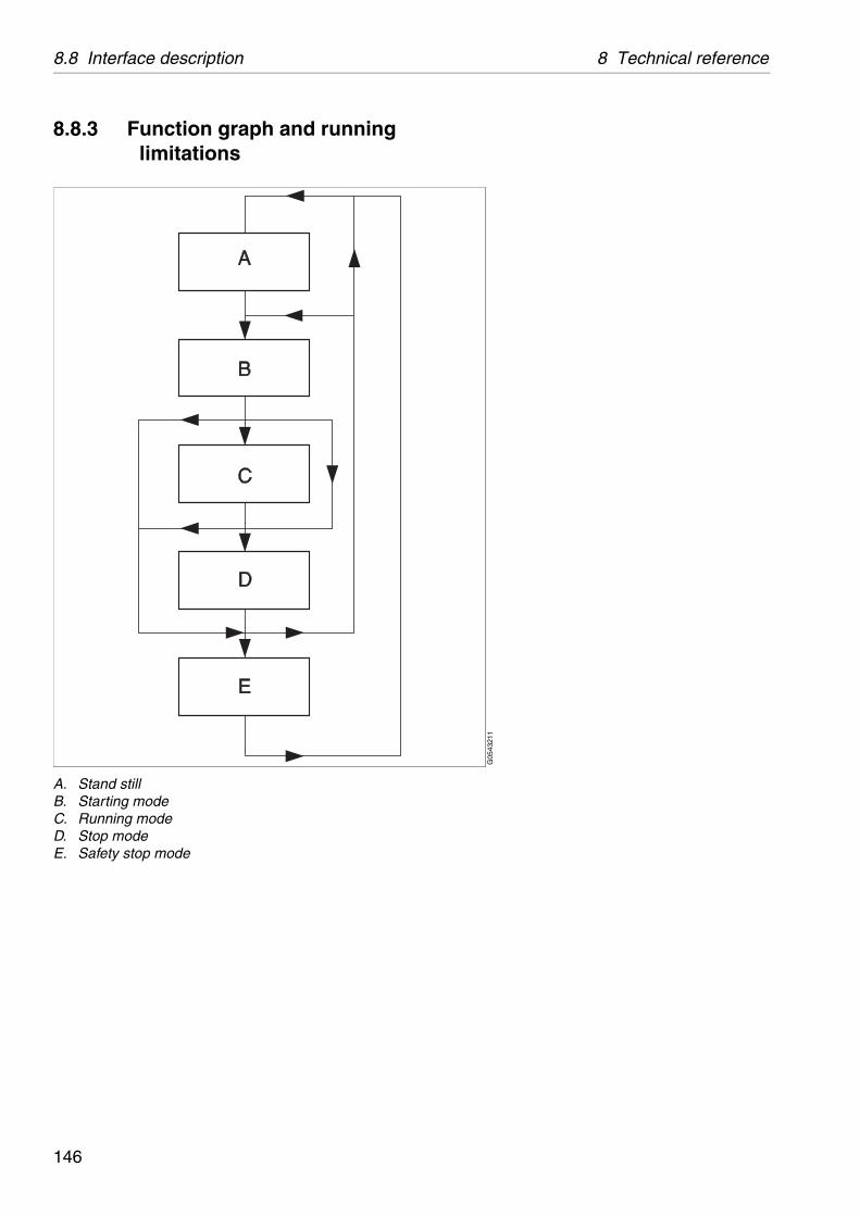
8.8 Interface description 8 Technical reference
G05
4321
1
8.8.3 Function graph and running limitations
A. Stand stillB. Starting modeC. Running modeD. Stop modeE. Safety stop mode
146
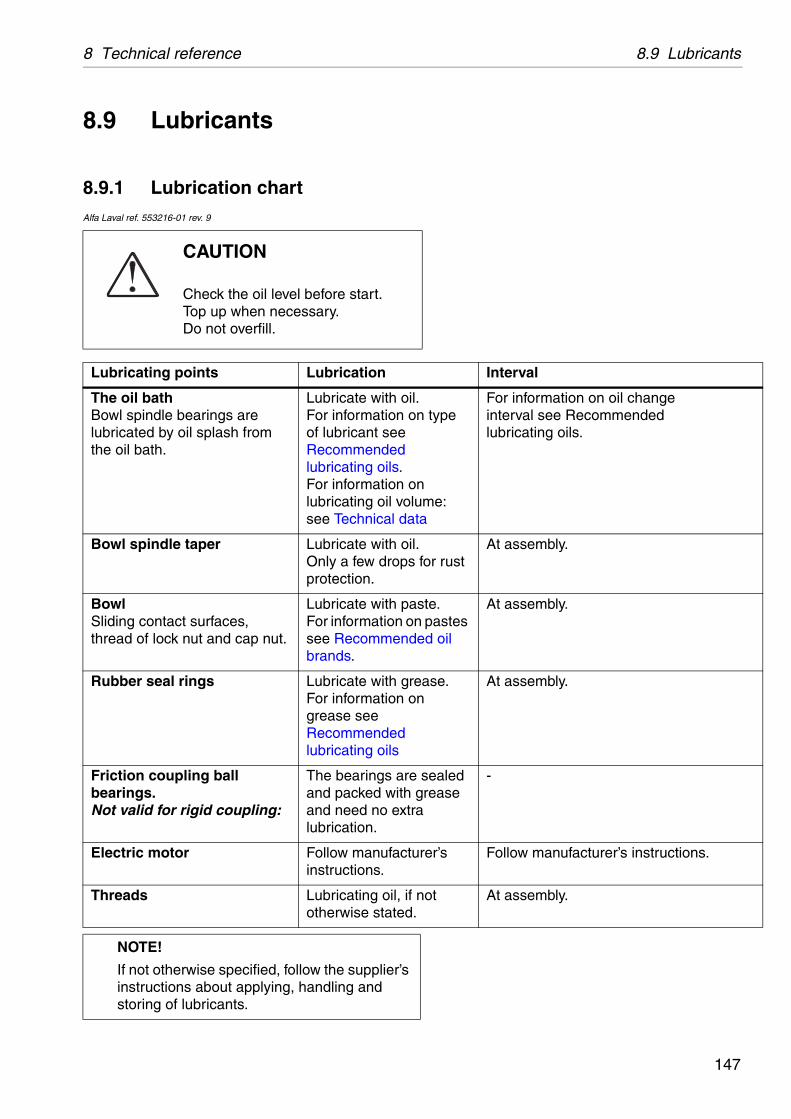
8 Technical reference 8.9 Lubricants
Interval
. n type
n me:
ta
For information on oil changeinterval see Recommendedlubricating oils.
. for rust
At assembly.
ste. pastes
ed oil
At assembly.
ase. n
At assembly.
sealed grease a
-
rer’s Follow manufacturer’s instructions.
not At assembly.
8.9 Lubricants
8.9.1 Lubrication chartAlfa Laval ref. 553216-01 rev. 9
CAUTION
Check the oil level before start. Top up when necessary.Do not overfill.
Lubricating points Lubrication
The oil bathBowl spindle bearings are lubricated by oil splash from the oil bath.
Lubricate with oilFor information oof lubricant see Recommended lubricating oils.For information olubricating oil volusee Technical da
Bowl spindle taper Lubricate with oilOnly a few dropsprotection.
BowlSliding contact surfaces, thread of lock nut and cap nut.
Lubricate with paFor information onsee Recommendbrands.
Rubber seal rings Lubricate with greFor information ogrease see Recommended lubricating oils
Friction coupling ball bearings.Not valid for rigid coupling:
The bearings areand packed with and need no extrlubrication.
Electric motor Follow manufactuinstructions.
Threads Lubricating oil, if otherwise stated.
NOTE!
If not otherwise specified, follow the supplier’s instructions about applying, handling and storing of lubricants.
147
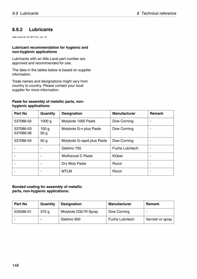
8.9 Lubricants 8 Technical reference
Manufacturer Remark
Dow Corning -
ste Dow Corning -
Paste Dow Corning -
Fuchs Lubritech -
Klüber -
Rocol -
Rocol -
Manufacturer Remark
y Dow Corning -
Fuchs Lubritech Varnish or spray
8.9.2 LubricantsAlfa Laval ref. 55 3217-01, rev. 14
Lubricant recommendation for hygienic and non-hygienic applications
Lubricants with an Alfa Laval part number are approved and recommended for use.
The data in the tables below is based on supplier information.
Trade names and designations might vary from country to country. Please contact your local supplier for more information.
Paste for assembly of metallic parts, non-hygienic applications:
Bonded coating for assembly of metallic parts, non-hygienic applications:
Part No Quantity Designation
537086-02 1000 g Molykote 1000 Paste
537086-03537086-06
100 g50 g
Molykote G-n plus Pa
537086-04 50 g Molykote G-rapid plus
- - Gleitmo 705
- - Wolfracoat C Paste
- - Dry Moly Paste
- - MTLM
Part No Quantity Designation
535586-01 375 g Molykote D321R Spra
- - Gleitmo 900
148
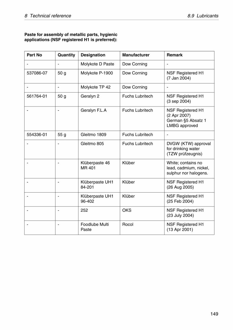
8 Technical reference 8.9 Lubricants
Manufacturer Remark
Dow Corning -
Dow Corning NSF Registered H1 (7 Jan 2004)
Dow Corning -
Fuchs Lubritech NSF Registered H1 (3 sep 2004)
Fuchs Lubritech NSF Registered H1 (2 Apr 2007)German §5 Absatz 1 LMBG approved
Fuchs Lubritech -
Fuchs Lubritech DVGW (KTW) approval for drinking water (TZW prüfzeugnis)
Klüber White; contains no lead, cadmium, nickel, sulphur nor halogens.
Klüber NSF Registered H1 (26 Aug 2005)
Klüber NSF Registered H1 (25 Feb 2004)
OKS NSF Registered H1 (23 July 2004)
Rocol NSF Registered H1 (13 Apr 2001)
Paste for assembly of metallic parts, hygienic applications (NSF registered H1 is preferred):
Part No Quantity Designation
- - Molykote D Paste
537086-07 50 g Molykote P-1900
- - Molykote TP 42
561764-01 50 g Geralyn 2
- - Geralyn F.L.A
554336-01 55 g Gleitmo 1809
- - Gleitmo 805
- - Klüberpaste 46 MR 401
- - Klüberpaste UH1 84-201
- - Klüberpaste UH1 96-402
- - 252
- - Foodlube Multi Paste
149

8.9 Lubricants 8 Technical reference
Manufacturer Remark
Bel-Ray NSF Registered H1 (16 December 2011)
Dow Corning Tested according to and complies with all National Formulary (NF) requirements for Dimethicone and European Pharmacopeia (EP) requirements for Dimeticone or Silicone Oil Used as a Lubricant, depending on viscosity.
Dow Corning NSF Registered H1 (3 June 2005)
Fuchs Lubritech NSF Registered H1 (30 March 2007)
Fuchs Lubritech DVGW approved according to the German KTW-recommendations for drinking water.
Klüber NSF Registered H1 (25 Feb 2004). Approved according to WRAS.
Klüber Complies with German Environmental Agency on hygiene requirements for tap water. Certified by DVGW-KTW, WRAS, AS4020, ACS.
MMCC NSF Registered H1 (25 March 2002)
Rocol NSF Registered H1 (18 April 2001)
Silicone grease/oil for rubber rings, hygienic and non-hygienic applications
Part No Quantity Designation
- - No-Tox Food GradeSilicone grease
- - Dow Corning 360 Medical Fluid
569415-01 50 g Molykote G 5032
- - Geralyn SG MD 2
- - Chemplex 750
- - Paraliq GTE 703
- - Unisilkon L 250 L
- - ALCO 220
- - Foodlube Hi-Temp
150

8 Technical reference 8.9 Lubricants
Manufacturer Remark
BP -
BP -
BP -
Castrol -
Castrol -
Chevron -
Chevron -
Dow Corning -
Dow Corning -
ExxonMobil -
ExxonMobil -
ExxonMobil -
Fuchs Lubritech -
Q8/Kuwait Petroleum
-
Shell -
SKF -
SKF -
SKF NSF Registered H1 (17 Aug 2007)
Total -
Always follow the lubrication recommendations of the bearing manufacturer.
Grease for ball and roller bearings in electric motors
Part No Quantity Designation
- - Energrease LS2
- - Energrease LS-EP2
- - Energrease MP-MG2
- - APS 2
- - Spheerol EPL 2
- - Multifak EP2
- - Multifak AFB 2
- - Molykote G-0101
- - Molykote Multilub
- - Unirex N2
- - Mobilith SHC 460
- - Mobilux EP2
- - Lagermeister EP2
- - Rembrandt EP2
- - Alvania EP 2
- - LGEP 2
- - LGMT 2
- - LGFP 2
- - Multis EP2
151

8.9 Lubricants 8 Technical reference
ion
ltra 220pha SP 320
chine oil 220 220
chine oil 220
oil BB
20
2 B 220
XA 220
220
nation-CKC to CKT 220
1517 – CLP 220
1524 – HLP 220
1524 – HVLP 220
8.9.3 Recommended oil brandsAlfa Laval ref. 553218-01, rev. 6
Mineral lubricating oil CKC 220 (Alfa Laval oil group A)
Trade names and designations might vary from country to country, Please contact your local supplier for more information.
Recommended oil brands
Requirements
Viscosity grade (ISO 3448/3104) VG 220 / Viscosity index (ISO 2909) VI > 90. The oil must have the correct viscosity grade. No other viscosity grade than specified should be used.
The oil must be endorsed for worm gear with bronze worm wheel.
The oil must follow the requirements in one of the standards below.
Manufacturer Designat
BP Castrol UCastrol Al
Chevron Clarity MaRando HDPaper Ma
ExxonMobil Mobil DTE
Q8/Kuwait Petroleum Wagner 2
Shell Morlina S
Statoil/Fuchs LubeWay
Total Cirkan ZS
Standard DesigISO 12925-1 ISO-L
DIN 51517 part 3 (German standard) DIN 5
DIN 51524 part 2 (German standard) DIN 5
DIN 51524 part 3 (German standard) DIN 5
NOTE
The use of other lubricants than the recommended is done on the exclusive responsibility of the user or oil supplier.
152

8 Technical reference 8.9 Lubricants
ion
Oil Extreme Pressure 220
pha SP 220ptigear BM 220
chine Oil 220ltra Gear 22020
P 220 600 XP 220
G 220
EP 220
220e Epona Z 220
gnation
-CKC/CKD/CKE/CKT 220
1517 - CLP 220
8.9.4 Recommended oil brandsAlfa Laval ref. 553218-02, rev. 7
Mineral lubricating oil CKE 220 (Alfa Laval oil group B)
Trade names and designations might vary from country to country, Please contact your local supplier for more information.
Recommended oil brands
Requirements
Viscosity grade (ISO 3448/3104) VG 220 / Viscosity index (ISO 2909) VI > 90. The oil must have the correct viscosity grade. No other viscosity grade than specified should be used.
The oil must be endorsed for worm gear with bronze worm wheel.
The oil must follow the requirements in one of the standards below.
Manufacturer Designat
Bel-Ray 100 Gear
BP Castrol AlCastrol O
Chevron Clarity MaMeropa UMeropa 2
ExxonMobil Spartan EMobilgear
Q8/Kuwait Petroleum Goya 220
Shell Omala S2
Statoil/Fuchs LoadWay
Total Carter EPLubmarin
Standard Desi
ISO 12925-1, (ISO 6743/6) ISO-L
DIN 51517 part 3 DIN 5
NOTE
The use of other lubricants than the recommended is done on the exclusive responsibility of the user or oil supplier.
153
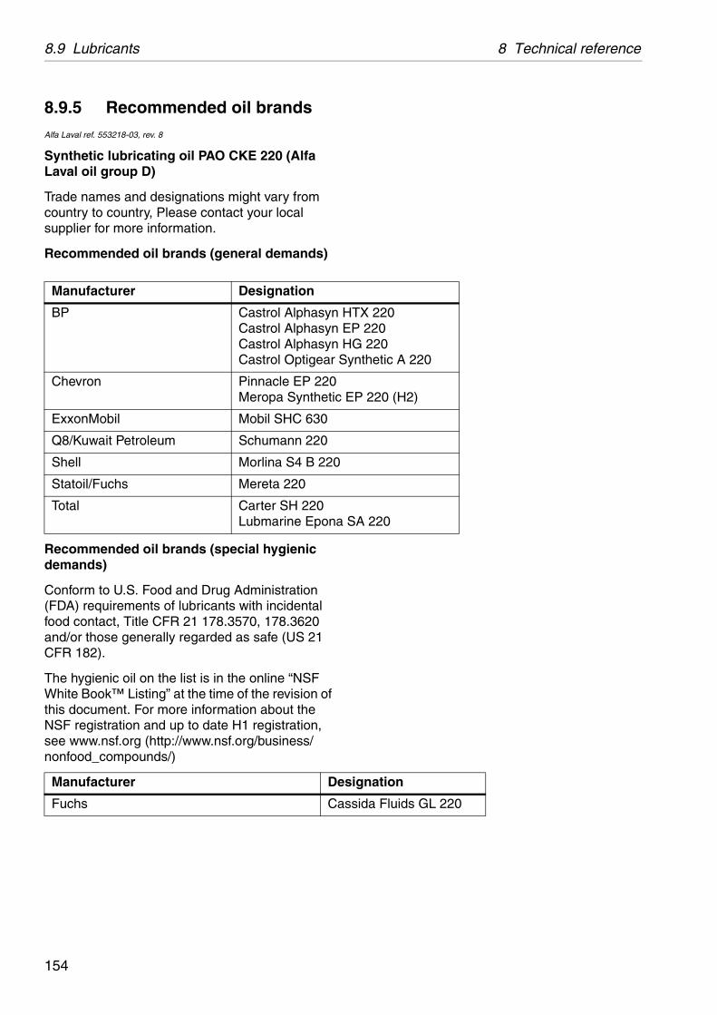
8.9 Lubricants 8 Technical reference
TX 220P 220G 220
ynthetic A 220
P 220 (H2)
SA 220
ignation
sida Fluids GL 220
8.9.5 Recommended oil brandsAlfa Laval ref. 553218-03, rev. 8
Synthetic lubricating oil PAO CKE 220 (Alfa Laval oil group D)
Trade names and designations might vary from country to country, Please contact your local supplier for more information.
Recommended oil brands (general demands)
Recommended oil brands (special hygienic demands)
Conform to U.S. Food and Drug Administration (FDA) requirements of lubricants with incidental food contact, Title CFR 21 178.3570, 178.3620 and/or those generally regarded as safe (US 21 CFR 182).
The hygienic oil on the list is in the online “NSF White Book™ Listing” at the time of the revision of this document. For more information about the NSF registration and up to date H1 registration, see www.nsf.org (http://www.nsf.org/business/nonfood_compounds/)
Manufacturer Designation
BP Castrol Alphasyn HCastrol Alphasyn ECastrol Alphasyn HCastrol Optigear S
Chevron Pinnacle EP 220Meropa Synthetic E
ExxonMobil Mobil SHC 630
Q8/Kuwait Petroleum Schumann 220
Shell Morlina S4 B 220
Statoil/Fuchs Mereta 220
Total Carter SH 220Lubmarine Epona
Manufacturer Des
Fuchs Cas
154
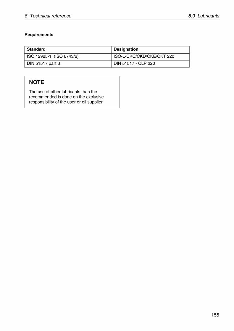
8 Technical reference 8.9 Lubricants
gnation
-CKC/CKD/CKE/CKT 220
1517 - CLP 220
Requirements
Standard Desi
ISO 12925-1, (ISO 6743/6) ISO-L
DIN 51517 part 3 DIN 5
NOTE
The use of other lubricants than the recommended is done on the exclusive responsibility of the user or oil supplier.
155
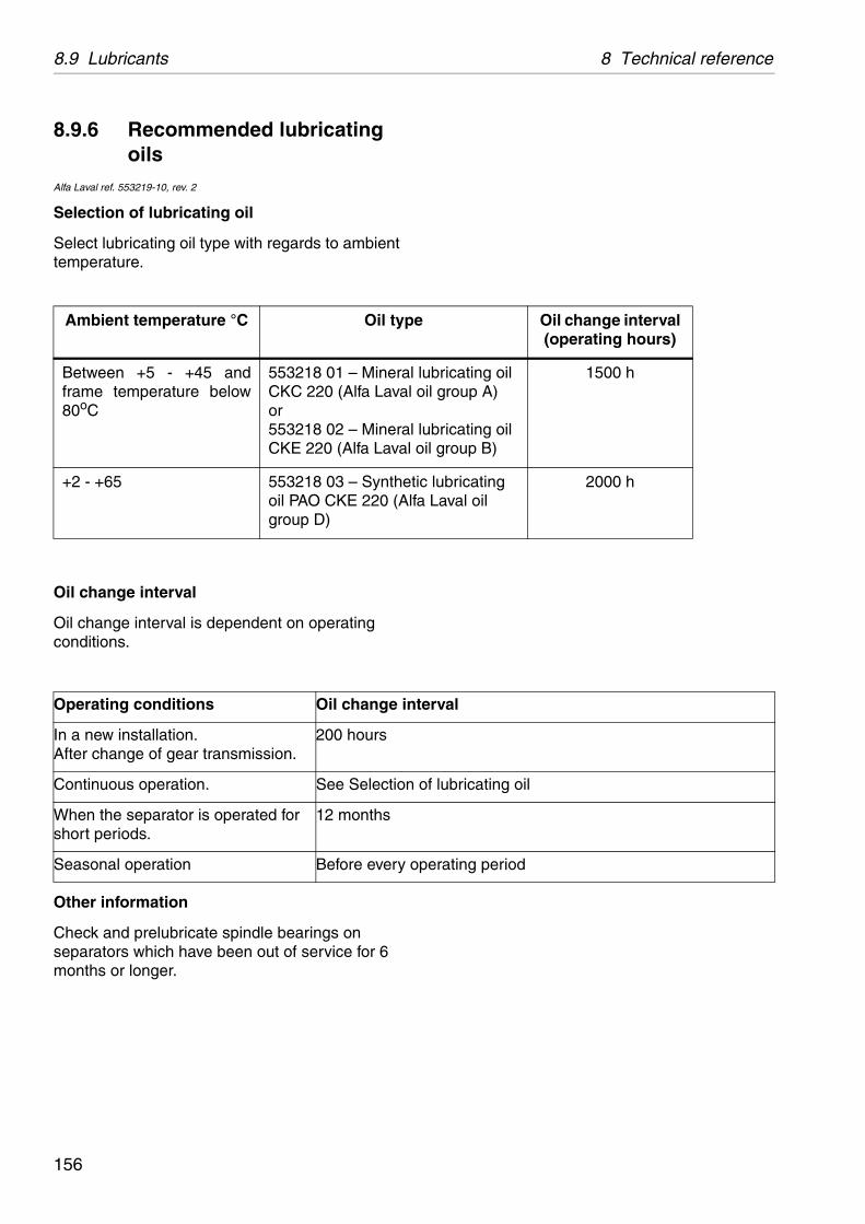
8.9 Lubricants 8 Technical reference
Oil change interval (operating hours)
lubricating oil il group A)
lubricating oil il group B)
1500 h
c lubricating Laval oil
2000 h
erval
of lubricating oil
perating period
8.9.6 Recommended lubricating oils
Alfa Laval ref. 553219-10, rev. 2
Selection of lubricating oil
Select lubricating oil type with regards to ambient temperature.
Oil change interval
Oil change interval is dependent on operating conditions.
Other information
Check and prelubricate spindle bearings on separators which have been out of service for 6 months or longer.
Ambient temperature °C Oil type
Between +5 - +45 and frame temperature below 80oC
553218 01 – Mineral CKC 220 (Alfa Laval oor553218 02 – Mineral CKE 220 (Alfa Laval o
+2 - +65 553218 03 – Synthetioil PAO CKE 220 (Alfagroup D)
Operating conditions Oil change int
In a new installation. After change of gear transmission.
200 hours
Continuous operation. See Selection
When the separator is operated for short periods.
12 months
Seasonal operation Before every o
156

8 Technical reference 8.10 Drawings
C01
436A
1
8.10 Drawings
8.10.1 Cross-section, complete separator
Complete separator
157

8.10 Drawings 8 Technical reference
G06
1511
1
8.10.2 Cross-section, horizontal driving device
Horizontal driving device
158
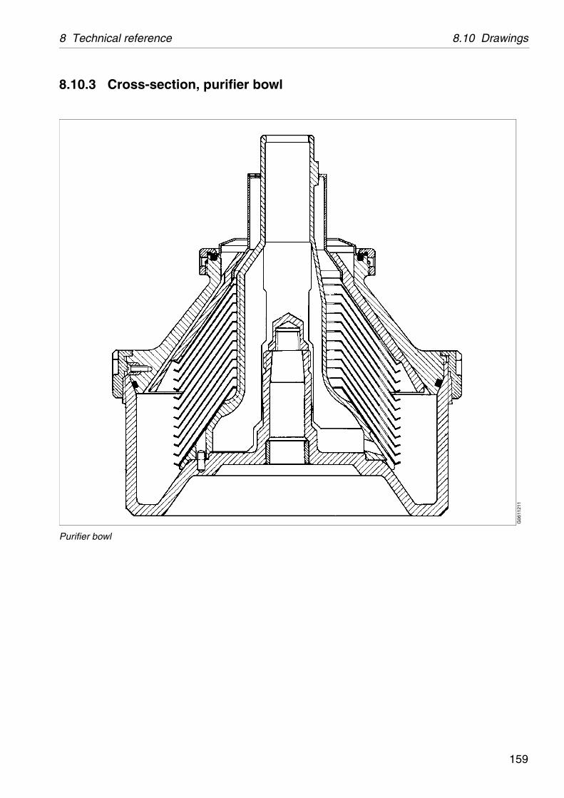
8 Technical reference 8.10 Drawings
G06
1121
1
8.10.3 Cross-section, purifier bowl
Purifier bowl
159

8.10 Drawings 8 Technical reference
G06
1131
1
8.10.4 Cross-section, clarifier bowl
Clarifier bowl
160

8 Technical reference 8.10 Drawings
G06
2611
1
8.10.5 Cross-section, pump
.
1. Sealing ring2. Coupling3. Retaining ring4. Sealing ring5. Pump impeller6. Pump impeller7. Shield8. Slotted tubular spring pin9. Slotted tubular spring pin
161
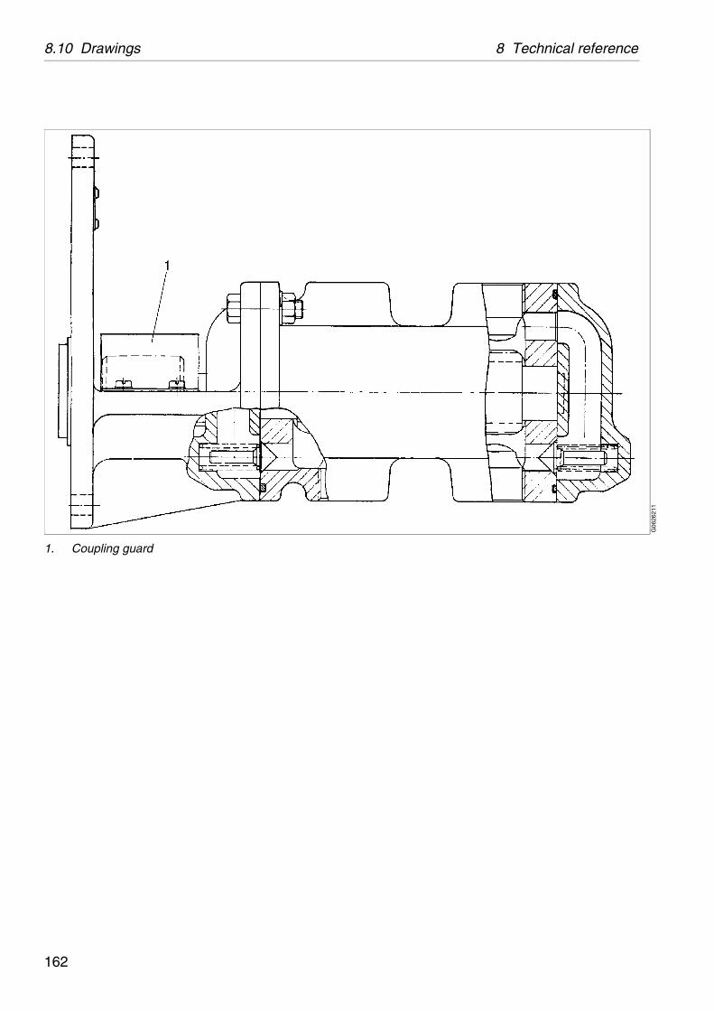
8.10 Drawings 8 Technical reference
G06
2621
1
1. Coupling guard
162

8 Technical reference 8.10 Drawings
G06
2631
1
8.10.6 Cross-section, water inlet device
1. Hose nipple2. Packing3. Sight glass4. Packing
163

8.10 Drawings 8 Technical reference
G06
2602
1
S00
6141
1
8.10.7 Machine plates and safety labels
Alfa Laval ref. 558097, rev. 1
1. Machine plate
Separator
Manufacturing serial No / Year
Product No
Bowl
Max. speed (bowl)
Direction of rotation (bowl)
Speed motor shaft
Frame
El. current frequency
Recommended motor power
Max. density of feed
Max. density of sediment
Process temperature min./max.
164

8 Technical reference 8.10 Drawings
S00
690N
1S
0063
211
S00
6311
1S
0068
811
S00
6911
1
3. Safety label
Text on label:
Warning
Read the instruction manuals before installation, operation and maintenance. Consider inspection intervals.
Failure to strictly follow instructions can lead to fatal injury.
If excessive vibration occurs, stop separator and keep bowl filled with liquid during rundown.
Out of balance vibration will become worse if bowl is not full.
Separator must stop rotating before any dismantling work is started.
4. Name plate
6. Power supply frequency
7. Arrow
Indicating direction of rotation of horizontal driving device.
9. Stop, follow lifting instruction
This transport label is not permanently fixed to the separator.
165

8.11 Electric motor 8 Technical reference
8.11 Electric motorFor information regarding motor specifications, see motor plate.
For further information see motor manufacturer's documentation.
NOTE
For complete information about motor variants, please contact your Alfa Laval representative.
166
8 Technical reference 8.12 Storage and installation
8.12 Storage and installation
8.12.1 Storage and transport of goods
Storage
Before storing a separator that has been in operation, make sure to drain any parts containing water, such as Operating water module (if any), Operating water system and Cooling jackets.
Specification
Upon arrival to the store, check all components and keep them:
1. Well stored and protected from mechanical damage.
2. Dry and protected from rain and humidity.
3. Organized in the store in such a way that the goods will be easily accessible when installation is about to take place.
167
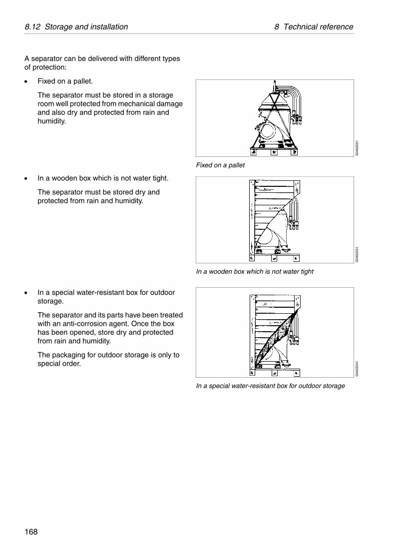
8.12 Storage and installation 8 Technical reference
G04
0202
1
Fixed on a pallet
G04
0203
1
In a wooden box which is not water tight
G04
0204
1
In a special water-resistant box for outdoor storage
A separator can be delivered with different types of protection:
Fixed on a pallet.
The separator must be stored in a storage room well protected from mechanical damage and also dry and protected from rain and humidity.
In a wooden box which is not water tight.
The separator must be stored dry and protected from rain and humidity.
In a special water-resistant box for outdoor storage.
The separator and its parts have been treated with an anti-corrosion agent. Once the box has been opened, store dry and protected from rain and humidity.
The packaging for outdoor storage is only to special order.
168

8 Technical reference 8.12 Storage and installation
Transport
Specification
During transport of the separator, the frame hood and bowl must always be removed from the machine.
When lifting a separator it must always be hung securely. See chapter ‘‘5.7 Lifting instructions” on page 83.
During erection, all inlets and outlets to separators and accessories must be covered to be protected from dirt and dust.
WARNING
Crush hazard
Use correct lifting tools and follow lifting instructions.
169

8.12 Storage and installation 8 Technical reference
G00
2061
1
Check the drawings when planning the installation
G00
2072
1
Suitable space must be obtained for the maintenance work
8.12.2 Planning and installation
Introduction
The requirements for one or more separators can be established by consulting the following documents.
Basic size drawing
Connection list
Interface description
Interconnection drawing
Foundation drawing
Lifting drawing
These are included in this chapter ‘‘8 Technical reference” on page 131.
Important measurements
Important measurements are the minimum lifting height for lifting tackle, shortest distance between driving motor and wall, free passage for dismantling and assembly, maintenance and operation.
Plan your installation with sufficient room for the controls and operation so that instruments are easily visible. Valves and controls must be within convenient reach. Pay attention to space requirements for maintenance work, work benches, dismantled machine parts or for a service trolley.
170
8 Technical reference 8.12 Storage and installation
Space for separator
The separator shall be placed in such a way that suitable space for maintenance and repair is obtained.
Specification
See the "Basic size drawings" on pages 139, 140 and 141 for the service space required with the separator installed.
Recommendation
The spanner for the large lock ring should have sufficient space to make a complete turn without hitting any of the ancillary equipment surrounding the separator.
171
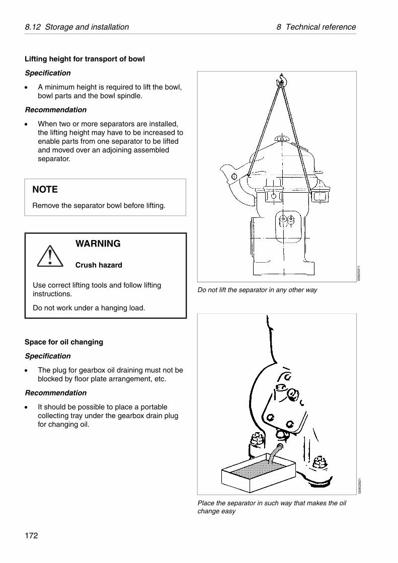
8.12 Storage and installation 8 Technical reference
G06
2591
1
Do not lift the separator in any other way
G06
0262
1
Place the separator in such way that makes the oil change easy
Lifting height for transport of bowl
Specification
A minimum height is required to lift the bowl, bowl parts and the bowl spindle.
Recommendation
When two or more separators are installed, the lifting height may have to be increased to enable parts from one separator to be lifted and moved over an adjoining assembled separator.
Space for oil changing
Specification
The plug for gearbox oil draining must not be blocked by floor plate arrangement, etc.
Recommendation
It should be possible to place a portable collecting tray under the gearbox drain plug for changing oil.
NOTE
Remove the separator bowl before lifting.
WARNING
Crush hazard
Use correct lifting tools and follow lifting instructions.
Do not work under a hanging load.
172

8 Technical reference 8.12 Storage and installation
G09
2051
1
Frame foot with vibration damper
1. Lock nut2. Nut3. Vibration damper
8.12.3 Foundations
Specification
The separator should be installed at floor level, see the "Basic size drawings" on page 141, 140 and 139.
The separator must be installed on a strong and rigid foundation to reduce the influence of vibrations from adjacent machinery.
Fit the separator frame on the foundation as follows:
1. Place the separator without vibration dampers (3) in position.
2. Check that the bolts do not press against the edges of the holes, otherwise the elasticity of the mounting of the separator frame will be impeded.
3. Check that the separator frame is horizontal and that all feet rest on the base plane.
4. Fit height adjusting washers required.
5. Lift the separator, fit the vibration dampers (3), lower and check that the bolts do not press against the edges of the holes.
6. Fit the nut (2) and tighten with 16 Nm. Hold the nut firmly and secure with the lock nut (1). Repeat for the other frame feet.
173
8.12 Storage and installation 8 Technical reference
174


