32
INSTRUCTION MANUAL ENC8/10 Enclosure 8/16 Copyright © 2016 Campbell Scientific, Inc.

INST
RU
CT
ION
MA
NU
AL
ENC8/10 Enclosure 8/16
C o p y r i g h t © 2 0 1 6 C a m p b e l l S c i e n t i f i c , I n c .


Limited Warranty “Products manufactured by CSI are warranted by CSI to be free from defects in materials and workmanship under normal use and service for twelve months from the date of shipment unless otherwise specified in the corresponding product manual. (Product manuals are available for review online at www.campbellsci.com.) Products not manufactured by CSI, but that are resold by CSI, are warranted only to the limits extended by the original manufacturer. Batteries, fine-wire thermocouples, desiccant, and other consumables have no warranty. CSI’s obligation under this warranty is limited to repairing or replacing (at CSI’s option) defective Products, which shall be the sole and exclusive remedy under this warranty. The Customer assumes all costs of removing, reinstalling, and shipping defective Products to CSI. CSI will return such Products by surface carrier prepaid within the continental United States of America. To all other locations, CSI will return such Products best way CIP (port of entry) per Incoterms ® 2010. This warranty shall not apply to any Products which have been subjected to modification, misuse, neglect, improper service, accidents of nature, or shipping damage. This warranty is in lieu of all other warranties, expressed or implied. The warranty for installation services performed by CSI such as programming to customer specifications, electrical connections to Products manufactured by CSI, and Product specific training, is part of CSI's product warranty. CSI EXPRESSLY DISCLAIMS AND EXCLUDES ANY IMPLIED WARRANTIES OF MERCHANTABILITY OR FITNESS FOR A PARTICULAR PURPOSE. CSI hereby disclaims, to the fullest extent allowed by applicable law, any and all warranties and conditions with respect to the Products, whether express, implied or statutory, other than those expressly provided herein.”

Assistance Products may not be returned without prior authorization. The following contact information is for US and international customers residing in countries served by Campbell Scientific, Inc. directly. Affiliate companies handle repairs for customers within their territories. Please visit www.campbellsci.com to determine which Campbell Scientific company serves your country.
To obtain a Returned Materials Authorization (RMA), contact CAMPBELL SCIENTIFIC, INC., phone (435) 227-9000. Please write the issued RMA number clearly on the outside of the shipping container. Campbell Scientific’s shipping address is:
CAMPBELL SCIENTIFIC, INC. RMA#_____ 815 West 1800 North Logan, Utah 84321-1784
For all returns, the customer must fill out a “Statement of Product Cleanliness and Decontamination” form and comply with the requirements specified in it. The form is available from our website at www.campbellsci.com/repair. A completed form must be either emailed to [email protected] or faxed to (435) 227-9106. Campbell Scientific is unable to process any returns until we receive this form. If the form is not received within three days of product receipt or is incomplete, the product will be returned to the customer at the customer’s expense. Campbell Scientific reserves the right to refuse service on products that were exposed to contaminants that may cause health or safety concerns for our employees.

Safety DANGER — MANY HAZARDS ARE ASSOCIATED WITH INSTALLING, USING, MAINTAINING, AND WORKING ON OR AROUND TRIPODS, TOWERS, AND ANY ATTACHMENTS TO TRIPODS AND TOWERS SUCH AS SENSORS, CROSSARMS, ENCLOSURES, ANTENNAS, ETC. FAILURE TO PROPERLY AND COMPLETELY ASSEMBLE, INSTALL, OPERATE, USE, AND MAINTAIN TRIPODS, TOWERS, AND ATTACHMENTS, AND FAILURE TO HEED WARNINGS, INCREASES THE RISK OF DEATH, ACCIDENT, SERIOUS INJURY, PROPERTY DAMAGE, AND PRODUCT FAILURE. TAKE ALL REASONABLE PRECAUTIONS TO AVOID THESE HAZARDS. CHECK WITH YOUR ORGANIZATION'S SAFETY COORDINATOR (OR POLICY) FOR PROCEDURES AND REQUIRED PROTECTIVE EQUIPMENT PRIOR TO PERFORMING ANY WORK.
Use tripods, towers, and attachments to tripods and towers only for purposes for which they are designed. Do not exceed design limits. Be familiar and comply with all instructions provided in product manuals. Manuals are available at www.campbellsci.com or by telephoning (435) 227-9000 (USA). You are responsible for conformance with governing codes and regulations, including safety regulations, and the integrity and location of structures or land to which towers, tripods, and any attachments are attached. Installation sites should be evaluated and approved by a qualified engineer. If questions or concerns arise regarding installation, use, or maintenance of tripods, towers, attachments, or electrical connections, consult with a licensed and qualified engineer or electrician.
General • Prior to performing site or installation work, obtain required approvals and permits. Comply
with all governing structure-height regulations, such as those of the FAA in the USA. • Use only qualified personnel for installation, use, and maintenance of tripods and towers, and
any attachments to tripods and towers. The use of licensed and qualified contractors is highly recommended.
• Read all applicable instructions carefully and understand procedures thoroughly before beginning work.
• Wear a hardhat and eye protection, and take other appropriate safety precautions while working on or around tripods and towers.
• Do not climb tripods or towers at any time, and prohibit climbing by other persons. Take reasonable precautions to secure tripod and tower sites from trespassers.
• Use only manufacturer recommended parts, materials, and tools.
Utility and Electrical • You can be killed or sustain serious bodily injury if the tripod, tower, or attachments you are
installing, constructing, using, or maintaining, or a tool, stake, or anchor, come in contact with overhead or underground utility lines.
• Maintain a distance of at least one-and-one-half times structure height, 20 feet, or the distance required by applicable law, whichever is greater, between overhead utility lines and the structure (tripod, tower, attachments, or tools).
• Prior to performing site or installation work, inform all utility companies and have all underground utilities marked.
• Comply with all electrical codes. Electrical equipment and related grounding devices should be installed by a licensed and qualified electrician.
Elevated Work and Weather • Exercise extreme caution when performing elevated work. • Use appropriate equipment and safety practices. • During installation and maintenance, keep tower and tripod sites clear of un-trained or non-
essential personnel. Take precautions to prevent elevated tools and objects from dropping. • Do not perform any work in inclement weather, including wind, rain, snow, lightning, etc.
Maintenance • Periodically (at least yearly) check for wear and damage, including corrosion, stress cracks,
frayed cables, loose cable clamps, cable tightness, etc. and take necessary corrective actions. • Periodically (at least yearly) check electrical ground connections.
WHILE EVERY ATTEMPT IS MADE TO EMBODY THE HIGHEST DEGREE OF SAFETY IN ALL CAMPBELL SCIENTIFIC PRODUCTS, THE CUSTOMER ASSUMES ALL RISK FROM ANY INJURY RESULTING FROM IMPROPER INSTALLATION, USE, OR MAINTENANCE OF TRIPODS, TOWERS, OR ATTACHMENTS TO TRIPODS AND TOWERS SUCH AS SENSORS, CROSSARMS, ENCLOSURES, ANTENNAS, ETC.


i
Table of Contents PDF viewers: These page numbers refer to the printed version of this document. Use the PDF reader bookmarks tab for links to specific sections.
1. Introduction ................................................................ 1
2. Precautions ................................................................ 2
3. Initial Inspection ......................................................... 2
4. QuickStart ................................................................... 3
4.1 Install Components .............................................................................. 3 4.2 Install the Mount .................................................................................. 3 4.3 Mount the Enclosure ............................................................................ 3
5. Overview ..................................................................... 4
6. Specifications ............................................................. 4
7. Installation .................................................................. 5
7.1 Mounting Equipment Inside the Enclosure .......................................... 5 7.1.1 Enclosure with One 1.5-inch Conduit ........................................... 5 7.1.2 Enclosure with Individual Entry Seals .......................................... 8
7.2 Attachment to an Instrument Mount .................................................... 9 7.2.1 Tripod Mast or T-post ................................................................... 9 7.2.2 Custom Mount ............................................................................ 10
8. Troubleshooting and Maintenance ......................... 10
8.1 When to Replace Desiccant ............................................................... 10 8.1.1 Humidity Indicator Card ............................................................. 10 8.1.2 Optional CS210 Humidity Sensor............................................... 10
8.2 Resistance to Weathering ................................................................... 10 8.2.1 Clear Acrylic Paint ...................................................................... 11 8.2.2 Primer and White Paint ............................................................... 11
8.3 Keeping Insects Out of the Enclosure ................................................ 11
Appendices
A. Door Switch ............................................................ A-1
A.1 Installation Procedure ..................................................................... A-1 A.2 Example CRBasic Program............................................................. A-4
B. 25458 5-inch DIN-Rail Mounting Kit ...................... B-1
B.1 Introduction ...................................................................................... B-1 B.2 Installation Procedure ...................................................................... B-1

Table of Contents
ii
Figures 1-1. ENC8/10 .............................................................................................. 1 3-1. Enclosure supply kit contents .............................................................. 3 4-1. ENC8/10 mounted on a T-post ............................................................ 4 7-1. Mounting components inside the enclosure ........................................ 5 7-2. Securing cables to the cable tie tabs .................................................... 6 7-3. Placement of enclosure accessories ..................................................... 7 7-4. Cable inserted into entry seal .............................................................. 8 7-5. Mounting the ENC8/10 to a mast ........................................................ 9 B-1. 15908 DIN-Rail Stopper installation ............................................... B-1 B-2. 15920 DIN-Rail Connector installation ........................................... B-2 B-3. 15907 End Plate installation ............................................................ B-2 B-4. 15909 Jumper installation ............................................................... B-3 B-5. DIN-rail bracket mounted onto an enclosure backplate .................. B-3 B-6. An installed and wired 25458 DIN-Rail Mounting Kit ................... B-4 B-7. The 25458 DIN-Rail Mounting Kit facilitates wiring of multiple
sensors .......................................................................................... B-4
CRBasic Examples A-1. Door Switch Wiring ........................................................................ A-4

1
ENC8/10 Enclosure 1. Introduction
The ENC8/10 environmental enclosure (FIGURE 1-1) protects dataloggers and peripherals from water and most pollutants. For cable entry, Campbell Scientific offers a choice of one 1.5-inch diameter conduit or six individual entry seals. Multiple cables can use the conduit, whereas each cable uses a separate entry seal. The individual entry seals provide a more watertight seal.
FIGURE 1-1. ENC8/10
The ENC8/10 excels in situations where a CR200X-series or CR300-series datalogger is mounted with a small power supply. It is also useful in situations where a communications or measurement peripheral needs to be mounted without the need for a datalogger.
Campbell Scientific enclosures are manufactured with non-corrosive polyester and reinforced with fiberglass. These white UV-stabilized enclosures reflect solar radiation, reducing temperature gradients inside the enclosure without requiring a separate radiation shield. A door gasket, external grounding lug, stainless steel hinge, and lockable hasp are included. Our enclosures were rated NEMA 6P before being modified to include conduit(s) or entry seals.

ENC8/10 Enclosure
2
Dataloggers, peripherals, and brackets are mounted to an internal backplate punched with a grid of one-inch-on-center holes.
2. Precautions • READ AND UNDERSTAND the Safety section at the front of this
manual.
• Always use the putty from the enclosure supply kit to seal the conduit opening to prevent moisture and insects from entering the enclosure.
• Use the desiccant pack from the enclosure supply kit to lower the humidity inside the enclosure.
• Ensure the enclosure is attached to a proper earth ground.
3. Initial Inspection • When unpacking the ENC8/10, inspect the packaging and contents for
damage. Any claims for shipping damage must be filed with the shipping company.
• Locate the packing slip for the order and compare the items listed on the packing slip to the items that were actually shipped. Report any discrepancies to Campbell Scientific.
• Locate the enclosure supply kit (FIGURE 3-1) and ensure all its components are present:
o #6-32 x 0.375 in screws (4)
o Grommets (4)
o 3 cm cable-tie tabs (2)
o 4 in cable ties (6)
o 8 in cable ties (2)
o Humidity indicator card (1)
o 4 oz container of sealing putty (2)
o 4-unit desiccant packs (2)
o Phillips screwdriver (1)
o PVC coupling (1)

ENC8/10 Enclosure
3
FIGURE 3-1. Enclosure supply kit contents
4. QuickStart The ENC8/10 is a small enclosure designed to hold a small datalogger such as the CR300 along with a power source such as the BPALK. The enclosure is also able to hold an SDM device or radio. Contact Campbell Scientific if there is a question about a component fitting inside the ENC8/10.
It is a good practice to fully assemble and test the system in the office before installing it in the field. This will confirm all wire connections are correct and the software program is functioning properly.
4.1 Install Components Determine the best placement of the components inside the enclosure. Take into account the wiring needed to connect the components to each other, and to any external sensors.
4.2 Install the Mount The ENC8/10 is easily mounted to a vertical mast such as the CM310 installed in a concrete foundation, or CM300 with the CM350 pedestal legs. It can also be mounted to any of the tripods available from Campbell Scientific. Another option is to mount the ENC8/10 to a T-post driven into the ground.
Prepare the site for the installation of the mast or tripod. Install the mast, tripod, or T-post in the desired location. Also, drive a ground rod into the ground next to the mount.
4.3 Mount the Enclosure The ENC8/10 enclosure mount includes the hardware necessary to secure the enclosure to a mount when ordered with the enclosure mounting option. Otherwise, the installer will need to provide mounting hardware.

ENC8/10 Enclosure
4
Secure the enclosure to the mount using the V-bolts or user-supplied hardware. FIGURE 4-1 shows the ENC8/10 mounted on a T-post.
FIGURE 4-1. ENC8/10 mounted on a T-post
5. Overview The ENC8/10 is a small enclosure that provides enough space for a power supply and one or two additional components, such as CR300-series datalogger or CDM device. Its small size allows it to be mounted traditionally on a mast, a user-supplied mount like a T-post, or the side of a building.
There are two options when ordering the ENC8/10 for cable entry. The first option is a 1.5-inch conduit for the cabling. The enclosure supply kit includes putty to seal the opening against moisture after the cables have been installed.
The second option includes six individual entry seals. After running a wire through an entry seal, the seal is tightened to secure the wire. This prevents moisture from being able to follow the path of the wire into the enclosure.
It is also possible to order the ENC8/10 without any enclosure holes for cable entry.
6. Specifications Dimensions (H x W x D) External: 304 x 239 x 165 mm (11.97 x 9.42 x 6.50 in) Internal: 248 x 197 x 159 mm (9.74 x 7.74 x 6.25 in)
Weight: 2.36 kg (5.20 lb)

ENC8/10 Enclosure
5
Conduit Size (-SC option): 38.1 mm (1.5 in)
Entry Seal Openings (-ES option): 4.00 to 8.00 mm (0.157 to 0.315 in)
Compliance: View the EU Declaration of Conformity at www.campbellsci.com/enc-8-10
7. Installation 7.1 Mounting Equipment Inside the Enclosure 7.1.1 Enclosure with One 1.5-inch Conduit
1. If installing the optional door switch, follow the procedure described in Appendix A, Door Switch (p. A-1).
2. Connect sensors and peripherals to the datalogger as shown in the corresponding manuals. FIGURE 7-1 also shows how to first insert the grommets and secure the component. To insert the grommet, push the points of the flanges into the center of any square hole. To remove a grommet without damage, remove the enclosure backplate and use pliers to pinch the grommet flanges together.
FIGURE 7-1. Mounting components inside the enclosure
3. Secure sensor and peripheral leads to the side of the enclosure using 8-inch cable ties and cable tie tabs (see FIGURE 7-2 and FIGURE 7-3).

ENC8/10 Enclosure
6
FIGURE 7-2. Securing cables to the cable tie tabs

ENC8/10 Enclosure
7
The adhesive of the cable tie tab may not stick during extremely cold temperatures or extremely high humidity. In these situations, fasten the cable tie tab to the backplate using a #6 screw and grommet or run the cable tie through two of the enclosure backplate holes.
Refer to FIGURE 7-3 for steps 3–6.
FIGURE 7-3. Placement of enclosure accessories
4. Place one of the desiccant packs from the enclosure supply kit inside the enclosure. Reseal the other pack inside the plastic bag to use later (see 8.1, When to Replace Desiccant (p. 10)).
5. Remove the backing from the humidity indicator card and attach the card to the right side of the enclosure.
6. Place a roll of putty around the sensor leads where they enter the enclosure.
7. Press the putty around the leads and into the conduit to form a tight seal.
NOTE
NOTE

ENC8/10 Enclosure
8
7.1.2 Enclosure with Individual Entry Seals 1. If installing the optional door switch, follow the procedure described in
Appendix A, Door Switch (p. A-1).
2. Use the #6 screws and plastic grommets (FIGURE 7-1A) to mount additional peripherals to the enclosure backplate (FIGURE 7-1B). To insert the grommet, push the points of the flanges into the center of any square hole. To remove a grommet without damage, remove the enclosure backplate and use pliers to pinch the grommet flanges together.
Remember to allow space for cables and cable connectors.
3. Route each sensor and peripheral lead through a unique entry seal (see FIGURE 7-4). Each entry seal ships with a plug that must be removed before inserting the sensor wire. To remove the plug, loosen the entry seal and remove the plug from inside the enclosure.
FIGURE 7-4. Cable inserted into entry seal
4. Connect sensors and peripherals to the datalogger as described in the sensor and peripheral manuals.
5. Secure sensor and peripheral leads to the side of the enclosure using 8-inch cable ties and cable tie tabs (see FIGURE 7-3).
The adhesive of the cable tie tab may not stick during extremely cold temperatures or extremely high humidity. In these situations, fasten the cable tie tab to the backplate using a #6 screw and grommet or run the cable tie through two of the enclosure backplate holes.
Refer to FIGURE 7-3 for steps 5–8.
NOTE
NOTE
NOTE

ENC8/10 Enclosure
9
6. Strain relief the sensor leads to the datalogger’s strain relief flanges with the 4-inch cable ties.
7. Place one of the desiccant packs from the enclosure supply kit inside of the enclosure. Reseal the other pack inside the plastic bag to use later (see Section 8.1, When to Replace Desiccant (p. 10)).
8. Remove the backing from the humidity indicator card and attach the card to the right side of the enclosure.
9. Rotate each entry seal so that the fitting clamps tightly against the sensor cable to provide a watertight seal (see FIGURE 7-4).
7.2 Attachment to an Instrument Mount 7.2.1 Tripod Mast or T-post
The “–EM” mount option is intended for mounting an enclosure to the mast of a tripod or a T-post. An enclosure ordered with this option will be shipped with a bracket mounted to the back of the enclosure.
Attach the enclosure to the mast as follows:
1. Position the enclosure on the north side of the mast.
2. Place the enclosure at the desired height. Please note that the recommended lead lengths for Campbell Scientific sensors assume the bottom of the enclosure is mounted three feet from the ground.
3. Use the furnished V-bolts, nuts, and washers to secure the enclosure to the tripod mast as shown in FIGURE 7-5. The second V-bolt is used at the bottom of the enclosure. FIGURE 4-1 shows the enclosure mounted on a T-post.
FIGURE 7-5. Mounting the ENC8/10 to a mast

ENC8/10 Enclosure
10
4. Route the 14 AWG wire from the brass tripod grounding clamp to the enclosure grounding lug. Strip one inch of insulation from each end of the wire and insert the end of the wire into the grounding lugs and tighten.
7.2.2 Custom Mount The “–NM” option is intended to allow the user to select their own mounting method. The user will be required to supply any mounting hardware. The ENC8/10 has a 0.31-inch hole at each back corner for mounting the enclosure to whatever surface the user has chosen.
8. Troubleshooting and Maintenance 8.1 When to Replace Desiccant
The humidity indicator card or optional CS210 Enclosure Humidity Sensor indicates when the desiccant needs to be replaced.
Because desiccant is inexpensive, Campbell Scientific recommends replacing desiccant packets once they become saturated rather than attempting to reactivate the desiccant.
8.1.1 Humidity Indicator Card The humidity indicator card has three colored circles that indicate the percentage of humidity. Desiccant packets inside the enclosure should be replaced with fresh packets when the upper dot on the indicator begins to turn pink. The indicator card does not need to be replaced unless the colored circles overrun.
8.1.2 Optional CS210 Humidity Sensor The CS210 Enclosure Humidity Sensor contains an Elan HM2000 series precision bulk polymer relative humidity sensor to measure relative humidity inside an enclosure. When the measurements exceed 35% relative humidity, replace the desiccant packets. Refer to the CS210 manual for sensor specifications, installation procedures, and programming information.
8.2 Resistance to Weathering Enclosures are coated to protect them from UV rays and other weathering. However, the outer surface of enclosures exposed to extreme weather (rain, wind, and/or UV rays) may erode so that glass fibers become apparent. The depth of the erosion is superficial and only affects the aesthetic appeal (for example, does not reduce the effectiveness in protecting equipment).
Customers who are worried about weathering can periodically rub the enclosure with petroleum jelly or a carnauba-based car wax. The appearance of an enclosure that has already been eroded can be sprayed with clear acrylic paint or coated with primer and white paint. Follow the procedure provided in either Section 8.2.1, Clear Acrylic Paint (p. 11), or Section 8.2.2, Primer and White Paint (p. 11), to ensure proper bonding.
CAUTION

ENC8/10 Enclosure
11
8.2.1 Clear Acrylic Paint 1. Use a rag and possibly a solvent to clean the outside of the enclosure.
Solvents that can be used include rubbing alcohol, a water solution of alkaline or caustic salts, domestic cleaning products such as Spic and Span®, aromatic hydrocarbon solvents (benzene, xylene), butyl acetate, and glycol acetate.
2. If a solvent was used, carefully rinse and dry enclosure.
3. Use a fine grain sandpaper to gently sand the enclosure surface; if the surface of the enclosure is sufficiently rough, this step may be skipped.
4. Spray with clear acrylic paint.
Properly ventilate the area while using solvent and paint. Wear safety goggles, mask, and gloves while sanding.
8.2.2 Primer and White Paint 1. Use a rag and possibly a solvent to clean the outside of the enclosure.
Solvents that can be used include rubbing alcohol, a water solution of alkaline or caustic salts, domestic cleaning products such as Spic and Span®, aromatic hydrocarbon solvents (benzene, xylene), butyl acetate, and glycol acetate.
2. If a solvent was used, carefully rinse and dry enclosure.
3. Use fine grain sandpaper to gently sand the enclosure surface; if the surface of the enclosure is sufficiently rough, this step may be skipped.
4. Spray with primer that is compatible with fiberglass.
5. Paint the enclosure with a white paint that is compatible with fiberglass and resistant to extreme weather. The paint must be white because the white color reflects solar radiation.
Properly ventilate the area while using solvent and paint. Wear safety goggles, mask, and gloves while sanding.
8.3 Keeping Insects Out of the Enclosure Campbell Scientific has published an application note regarding how to keep pests away from the equipment. It is found on the Campbell Scientific website (www.campbellsci.com/app-notes) and is called “Keeping Pests Away from Equipment (5-Y).”
Here are two methods from the application note on how to keep insects out of the enclosure.
1. Place moth balls or crystals in enclosures to prevent fire ants, wasps, spiders, and other insects from nesting.
CAUTION
CAUTION

ENC8/10 Enclosure
12
The fumes of moth balls or crystals could be hazardous. Therefore, enclosures that contain moth balls or crystals should be opened in a well-ventilated area.
2. Put animal ear tags in the enclosure. Some ear tags are treated with an insecticide. Talk with personnel in an agricultural store to determine the best ear tag for controlling the pests in your area. (This technique originated in Southern Texas.)
CAUTION

A-1
Appendix A. Door Switch A.1 Installation Procedure
1. The Enclosure Door-Open Indicator Kit contains several small brackets used to mount the sensor and magnet to the enclosure case and door. The brackets used depends on the style of enclosure. Use the following guide to determine the proper brackets:
a. The door open indicator is mounted at the upper right corner of the enclosure. The enclosure door determines which bracket is used to mount the sensor inside the enclosure case. If there is an offset near the edge of the enclosure door (see below), the sensor will be mounted with the brackets shown.
b. If there is no offset near the edge of the enclosure door, use the bracket as shown below.
DoorEdge
WeatherStripping
SensorMagnet
Offset Large Bracket
Sensor
Large Bracket Insert
Door Edge
WeatherStripping
SensorMagnet
No Offset
Small Bracket
Sensor
Appendix A. Door Switch
A-2
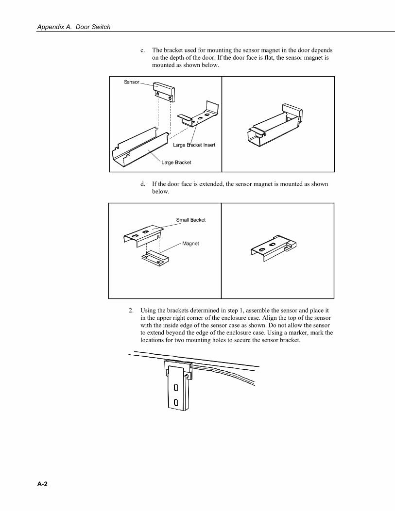
c. The bracket used for mounting the sensor magnet in the door depends on the depth of the door. If the door face is flat, the sensor magnet is mounted as shown below.
d. If the door face is extended, the sensor magnet is mounted as shown below.
2. Using the brackets determined in step 1, assemble the sensor and place it in the upper right corner of the enclosure case. Align the top of the sensor with the inside edge of the sensor case as shown. Do not allow the sensor to extend beyond the edge of the enclosure case. Using a marker, mark the locations for two mounting holes to secure the sensor bracket.
Large Bracket
Sensor
Large Bracket Insert
Small Bracket
Magnet

Appendix A. Door Switch
A-3
3. Assemble the sensor magnet with the bracket determined in step 1. Place the bracket in position so the edge of the sensor magnet does not extend beyond the internal edge of the door. Mark the locations for two mounting holes to secure the sensor magnet bracket.
The mounting holes for the sensor magnet bracket must align with the holes for the sensor bracket for the door open switch to function properly.
4. Drill small pilot holes, #36 (0.1065) or smaller, for all four mounting holes from the inside of the case.
5. Drill the final holes for the brackets from the outside of the enclosure using a #22 (0.157 inch) drill bit.
Drilling the holes in this manner will ensure the enclosure finish does not crack.
6. From the outside of the enclosure, insert two screws through the newly drilled holes in the case.
Mounting Holes
Mounting Holes
Flat DoorExtended Door
NOTE
NOTE

Appendix A. Door Switch
A-4
7. Place the assembled sensor bracket over the two screws, making sure the sensor is aligned with the inside edge of the case. Secure the bracket in place with two locknuts.
8. From the outside of the enclosure door, insert two screws through the new holes in the enclosure door.
9. Place the assembled sensor magnet bracket over the two screws, making sure the sensor magnet is aligned with the inside edge of the door. Secure the bracket in place with two locknuts.
A.2 Example CRBasic Program
CRBasic Example A-1. Door Switch Wiring
'Program name: DOOR SWITCH CR1000.CR1 ' Door Switch Wiring ' +5V black - power to door switch ' C1 black - signal to control port 3 '\\\\\\\\\\\\\\\\\\\\\\\\\ DECLARATIONS ///////////////////////// Public DOOR_open_1 Public DOOR_output '\\\\\\\\\\\\\\\\\\\\\\\\ OUTPUT SECTION //////////////////////// DataTable(Table101,true,-1) DataInterval(0,5,Min,10) Sample(1, DOOR_output, FP2)
Mounting Bracket
Enclosure
Sensor
Screw
Lock Nut

Appendix A. Door Switch
A-5
EndTable DataTable(Table102,true,-1) DataInterval(0,5,Min,10) Histogram(DOOR_open_1, FP2, 0, 1,001, 1 , 0.5, 1.5) EndTable '\\\\\\\\\\\\\\\\\\\\\\\\\\\ PROGRAM //////////////////////////// BeginProg Scan(1,Sec, 3, 0) ' Configure control ports as inputs or outputs PortsConfig (&B11111111,&B00000000) ' Measure Door switch ' (0=low=closed, 1=high=open) If CheckPort(1) = true then DOOR_open_1 = 1 Else DOOR_open_1 = 0 EndIf ' Two of many possible methods to output the status of the door open switch ' - assumes 5 minute data: ' Method #1: If the door is open even one reading during the output interval, ' output a 1 for the Door variable ' If (DOOR_open_1 = 1) Then DOOR_output = 1 EndIf CallTable Table101 ' Reset door status after output interval If TimeInToInterval(0,5,Min) Then DOOR_output = 0 EndIf ' Method #2: Door open status may be recorded as a fraction of the output ' interval (between 0 and 1) using the Histogram instruction. CallTable Table102 NextScan EndProg

Appendix A. Door Switch
A-6

B-1
Appendix B. 25458 5-inch DIN-Rail Mounting Kit B.1 Introduction
The 25458 5-inch DIN-Rail Mounting Kit can facilitate wiring when many wires need to be connected to one terminal. The kit contains one 15906 5-inch DIN-Rail Mounting Bracket, two 505 Screws, two 6044 Grommets, and two 15908 DIN-Rail Stoppers. A complete configuration will also include part number 15920 Spring-Loaded DIN-Rail Connectors, part number 15907 End Plates, and part number 15909 Jumpers. The stoppers, DIN-rail connectors, and end plates are mounted onto the DIN-rail bracket. The DIN-rail bracket is mounted to an enclosure backplate using the kit’s screws and grommets.
One DIN-rail connector (pn 15920) consists of three spring-loaded “guillotine” terminals that provide connection points for individual wires. Up to 20 of these DIN-rail connectors may be fastened to the 25458 DIN-Rail Bracket. The 15907 End Plates separate the DIN-rail connectors. The 15909 Jumpers are used to electrically connect the terminals. A stopper needs to be on each end of the DIN-rail connector assembly.
B.2 Installation Procedure 1. Mount the 15908 DIN-Rail Stoppers, 15920 DIN-Rail Connectors, and
15907 End Plates onto the DIN-rail bracket (see FIGURE B-1 through FIGURE B-3).
FIGURE B-1. 15908 DIN-Rail Stopper installation

Appendix B. 25458 5-inch DIN-Rail Mounting Kit
B-2
FIGURE B-2. 15920 DIN-Rail Connector installation
FIGURE B-3. 15907 End Plate installation

Appendix B. 25458 5-inch DIN-Rail Mounting Kit
B-3
2. Insert the 15909 Jumpers in the DIN-rail connectors as shown in FIGURE B-4.
FIGURE B-4. 15909 Jumper installation
3. Mount the DIN-rail bracket onto the enclosure backplate using two 505 Screws and two 6044 Grommets (see FIGURE B-5).
FIGURE B-5. DIN-rail bracket mounted onto an enclosure backplate
4. Connect the wires to the terminals (see FIGURE B-6 and FIGURE B-7). The 8125 Flat-Bladed Screwdriver is used to open the terminals’ guillotines for wire entry.

Appendix B. 25458 5-inch DIN-Rail Mounting Kit
B-4
FIGURE B-6. An installed and wired 25458 DIN-Rail Mounting Kit
FIGURE B-7. The 25458 DIN-Rail Mounting Kit facilitates wiring of multiple sensors


Campbell Scientific Companies
Campbell Scientific, Inc. 815 West 1800 North Logan, Utah 84321 UNITED STATES
www.campbellsci.com • [email protected]
Campbell Scientific Africa Pty. Ltd. PO Box 2450
Somerset West 7129 SOUTH AFRICA
www.campbellsci.co.za • [email protected]
Campbell Scientific Southeast Asia Co., Ltd. 877/22 Nirvana@Work, Rama 9 Road
Suan Luang Subdistrict, Suan Luang District Bangkok 10250
THAILAND www.campbellsci.asia • [email protected]
Campbell Scientific Australia Pty. Ltd. PO Box 8108
Garbutt Post Shop QLD 4814 AUSTRALIA
www.campbellsci.com.au • [email protected]
Campbell Scientific (Beijing) Co., Ltd. 8B16, Floor 8 Tower B, Hanwei Plaza
7 Guanghua Road Chaoyang, Beijing 100004
P.R. CHINA www.campbellsci.com • [email protected]
Campbell Scientific do Brasil Ltda. Rua Apinagés, nbr. 2018 ─ Perdizes CEP: 01258-00 ─ São Paulo ─ SP
BRASIL www.campbellsci.com.br • [email protected]
Campbell Scientific Canada Corp. 14532 – 131 Avenue NW Edmonton AB T5L 4X4
CANADA www.campbellsci.ca • [email protected]
Campbell Scientific Centro Caribe S.A. 300 N Cementerio, Edificio Breller
Santo Domingo, Heredia 40305 COSTA RICA
www.campbellsci.cc • [email protected]
Campbell Scientific Ltd. Campbell Park
80 Hathern Road Shepshed, Loughborough LE12 9GX
UNITED KINGDOM www.campbellsci.co.uk • [email protected]
Campbell Scientific Ltd. 3 Avenue de la Division Leclerc
92160 ANTONY FRANCE
www.campbellsci.fr • [email protected]
Campbell Scientific Ltd. Fahrenheitstraße 13
28359 Bremen GERMANY
www.campbellsci.de • [email protected]
Campbell Scientific Spain, S. L. Avda. Pompeu Fabra 7-9, local 1
08024 Barcelona SPAIN
www.campbellsci.es • [email protected]
Please visit www.campbellsci.com to obtain contact information for your local US or international representative.


